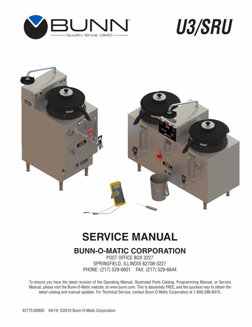
To ensure you have the latest revision of the Operating Manual, Illustrated Parts Catalog, Programming Manual, or Service Manual, please visit the Bunn-O-Matic website, at www.bunn.com. This is absolutely FREE, and the quickest way to obtain the
latest catalog and manual updates. For Technical Service, contact Bunn-O-Matic Corporation at 1-800-286-6070.
Page 2 42770 031314
BUNN-O-MATIC COMMERCIAL PRODUCT WARRANTYBunn-O-Matic Corp. (“BUNN”) warrants equipment manufactured by it as follows:
1) Airpots, thermal carafes, decanters, GPR servers, iced tea/coffee dispensers, MCR/MCP/MCA single cup brewers, ther-mal servers and ThermoFresh® servers (mechanical and digital) 1 year parts and 1 year labor.2) All other equipment - 2 years parts and 1 year labor plus added warranties as specified below:a) Electronic circuit and/or control boards - parts and labor for 3 years.b) Compressors on refrigeration equipment - 5 years parts and 1 year labor.c) Grinding burrs on coffee grinding equipment to grind coffee to meet original factory screen sieve analysis - parts and labor for 4 years or 40,000 pounds of coffee, whichever comes first.
These warranty periods run from the date of installation BUNN warrants that the equipment manufactured by it will be commercially free of defects in material and workmanship existing at the time of manufacture and appearing within the applicable warranty period. This warranty does not apply to any equipment, component or part that was not manufactured by BUNN or that, in BUNN’s judgment, has been affected by misuse, neglect, alteration, improper installation or operation, improper maintenance or repair, non periodic cleaning and descaling, equipment failures related to poor water quality, damage or casualty. In addition, the warranty does not apply to replacement of items subject to normal use including but not limited to user replaceable parts such as seals and gaskets. This warranty is conditioned on the Buyer 1) giving BUNN prompt notice of any claim to be made under this warranty by telephone at (217) 529-6601 or by writing to Post Office Box3227, Springfield, Illinois 62708-3227; 2) if requested by BUNN, shipping the defective equipment prepaid to an authorized BUNN service location; and 3) receiving prior authorization from BUNN that the defective equipment is under warranty.THE FOREGOING WARRANTY IS EXCLUSIVE AND IS IN LIEU OF ANY OTHER WARRANTY, WRITTEN OR ORAL, EX-PRESS OR IMPLIED, INCLUDING, BUT NOT LIMITED TO, ANY IMPLIED WARRANTY OF EITHER MERCHANTABILITY OR FITNESS FOR A PARTICULAR PURPOSE. The agents, dealers or employees of BUNN are not authorized to make modi-fications to this warranty or to make additional warranties that are binding on BUNN. Accordingly, statements by such individuals, whether oral or written, do not constitute warranties and should not be relied upon.If BUNN determines in its sole discretion that the equipment does not conform to the warranty, BUNN, at its exclusive op-tion while the equipment is under warranty, shall either 1) provide at no charge replacement parts and/or labor (during the applicable parts and labor warranty periods specified above) to repair the defective components, provided that this repair is done by a BUNN Authorized Service Representative; or 2) shall replace the equipment or refund the purchase price for the equipment.THE BUYER’S REMEDY AGAINST BUNN FOR THE BREACH OF ANY OBLIGATION ARISING OUT OF THE SALE OF THIS EQUIPMENT, WHETHER DERIVED FROM WARRANTY OR OTHERWISE, SHALL BE LIMITED, AT BUNN’S SOLE OPTION AS SPECIFIED HEREIN, TO REPAIR, REPLACEMENT OR REFUND.
In no event shall BUNN be liable for any other damage or loss, including, but not limited to, lost profits, lost sales, loss of use of equipment, claims of Buyer’s customers, cost of capital, cost of down time, cost of substitute equipment, facilities or services, or any other special, incidental or consequential damages.
392, A Partner You Can Count On, Air Infusion, AutoPOD, AXIOM, BrewLOGIC, BrewMETER, Brew Better Not Bitter, Brew-WISE, BrewWIZARD, BUNN Espress, BUNN Family Gourmet, BUNN Gourmet, BUNN Pour-O-Matic, BUNN, BUNN with the stylized red line, BUNNlink, Bunn-OMatic, Bunn-O-Matic, BUNNserve, BUNNSERVE with the stylized wrench design, Cool Froth, DBC, Dr. Brew stylized Dr. design, Dual, Easy Pour, EasyClear, EasyGard, FlavorGard, Gourmet Ice, Gourmet Juice, High Intensity, iMIX, Infusion Series, Intellisteam, My Café, Phase Brew, PowerLogic, Quality Beverage Equipment Worldwide, Respect Earth, Respect Earth with the stylized leaf and coffee cherry design, Safety-Fresh, savemycoffee.com, Scale-Pro, Silver Series, Single, Smart Funnel, Smart Hopper, SmartWAVE, Soft Heat, SplashGard, The Mark of Quality in Beverage Equipment Worldwide, ThermoFresh, Titan, trifecta, TRIFECTA (sylized logo), Velocity Brew, Air Brew, Beverage Bar Creator, Beverage Profit Calculator, Brew better, not bitter., Build-A-Drink, BUNNSource, Coffee At Its Best, Cyclonic Heating System, Daypart, Digital Brewer Control, Element, Milk Texturing Fusion, Nothing Brews Like a BUNN, Picture Prompted Cleaning, Pouring Profits, Signature Series, Sure Tamp, Tea At Its Best, The Horizontal Red Line, Ultra are either trademarks or registered trademarks of Bunn-O-Matic Corporation. The commercial trifecta® brewer housing configura-tion is a trademark of Bunn-O-Matic Corporation.
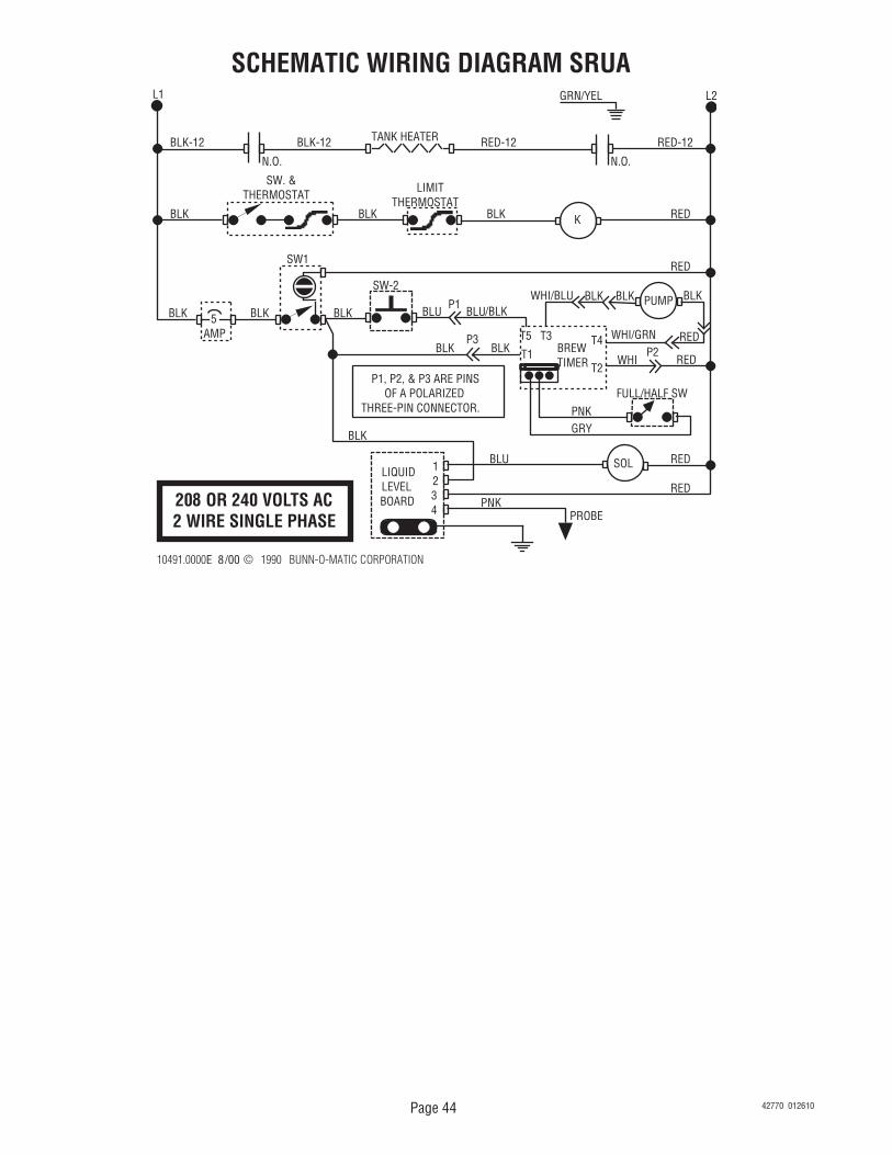
Water lines and valves to the brewer must be open.
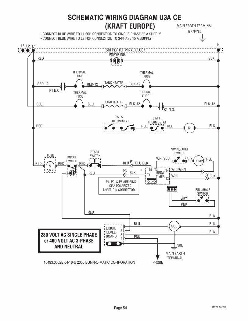
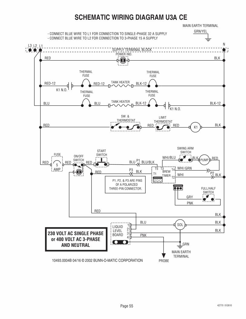
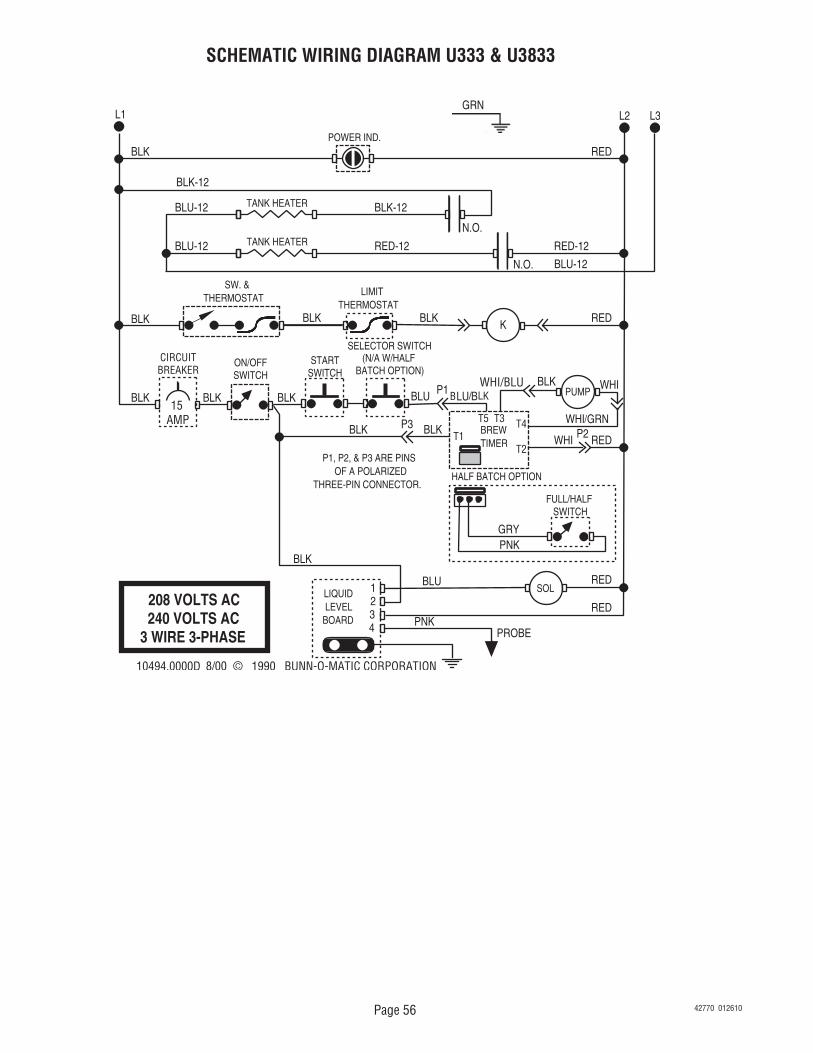
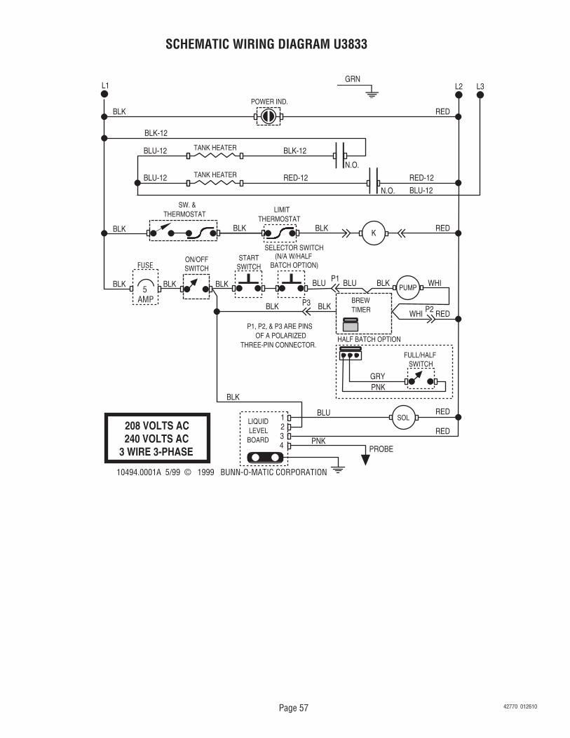
(A1) Check the terminal block for 120 volts ac across the red and white terminals and the black and white terminal on three wire 102/208 volt or 120/240 volt models.(A2) Check the terminal block for 208 volts ac, 230 volts ac or 240 volts ac on "A Series" brewers across the red and black terminals on two wire single phase 208 volt, 230 volt and 240 volt models.(A3) Check the terminal block for 208 volts ac, 240 volts ac, 380 volts ac across the black and blue terminals, the blue and red and the black and red terminals on three wire three phase 208 volt, 240 volt and 380 volt models.
TROUBLESHOOTINGA troubleshooting guide is provided to suggest probable causes and remedies for the most likely problems
encountered. If the problem remains after exhausting the troubleshooting steps, contact the Bunn-O-Matic Technical Service Department.
• Inspection, testing, and repair of electrical equipment should be performed only by qualified service person-nel.
• All electronic components have 120 volt ac and low voltage dc potential on their terminals. Shorting of terminals or the application of external voltages may result in board failure.
• Intermittent operation of electronic circuit boards is unlikely. Board failure will normally be permanent. If an intermittent condition is encountered, the cause will likely be a switch contact or a loose connection at a terminal or crimp.
• Solenoid removal requires interrupting the water supply to the valve. Damage may result if solenoids are energized for more than ten minutes without a supply of water.
• The use of two wrenches is recommended whenever plumbing fittings are tightened or loosened. This will help to avoid twists and kinks in the tubing.
• Make certain that all plumbing connections are sealed and electrical connections tight and isolated.• This brewer is heated at all times. Keep away from combustibles.
WARNING – • Exercise extreme caution when servicing electrical equipment. • Unplug the brewer when servicing, except when electrical tests are specified. • Follow recommended service procedures • Replace all protective shields or safety notices
42770 012610
Page 5
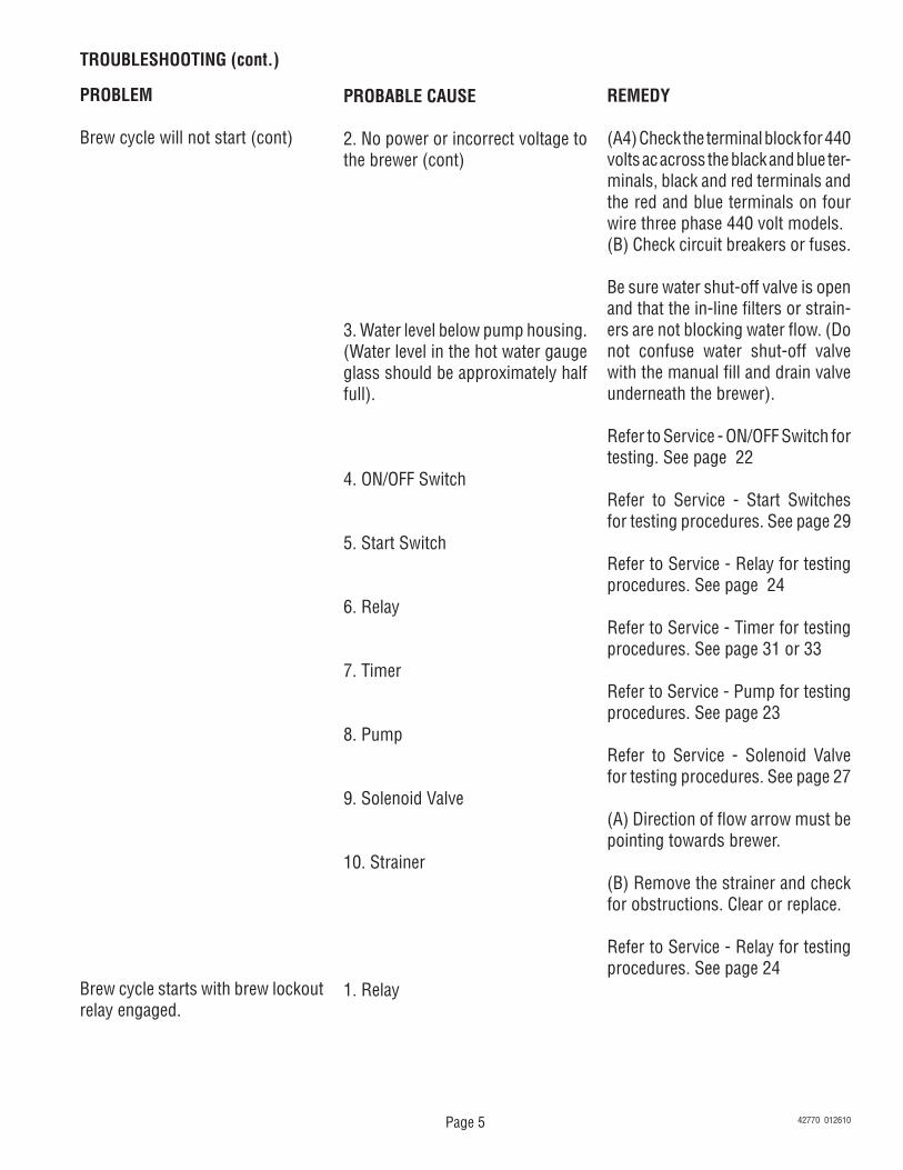
TROUBLESHOOTING (cont.)
PROBLEM
Brew cycle will not start (cont)
Brew cycle starts with brew lockout relay engaged.
PROBABLE CAUSE
2. No power or incorrect voltage to the brewer (cont)
3. Water level below pump housing. (Water level in the hot water gauge glass should be approximately half full).
4. ON/OFF Switch
5. Start Switch
6. Relay
7. Timer
8. Pump
9. Solenoid Valve
10. Strainer
1. Relay
REMEDY
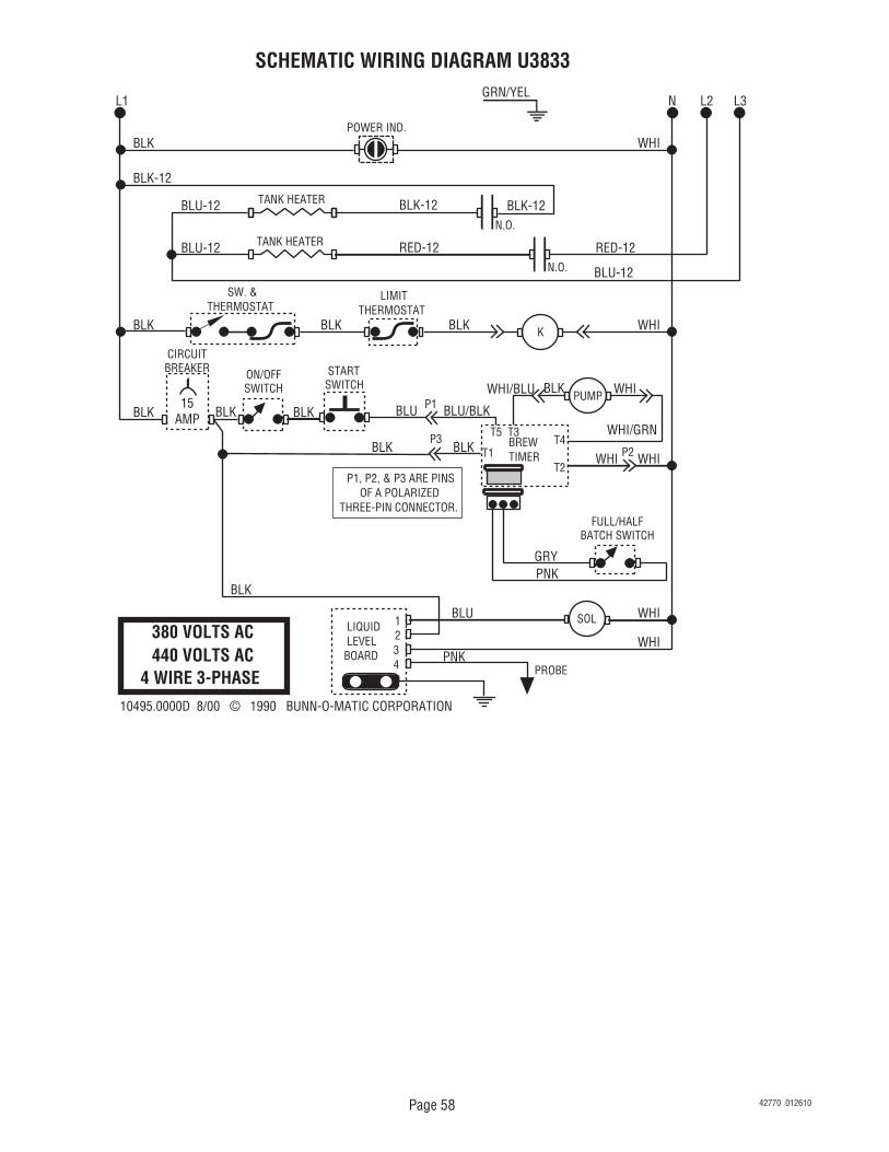
(A4) Check the terminal block for 440 volts ac across the black and blue ter-minals, black and red terminals and the red and blue terminals on four wire three phase 440 volt models. (B) Check circuit breakers or fuses.
Be sure water shut-off valve is open and that the in-line filters or strain-ers are not blocking water flow. (Do not confuse water shut-off valve with the manual fill and drain valve underneath the brewer).
Refer to Service - ON/OFF Switch for testing. See page 22
Refer to Service - Start Switches for testing procedures. See page 29
Refer to Service - Relay for testing procedures. See page 24
Refer to Service - Timer for testing procedures. See page 31 or 33
Refer to Service - Pump for testing procedures. See page 23
Refer to Service - Solenoid Valve for testing procedures. See page 27
(A) Direction of flow arrow must be pointing towards brewer.
(B) Remove the strainer and check for obstructions. Clear or replace.
Refer to Service - Relay for testing procedures. See page 24
42770 012610
Page 6
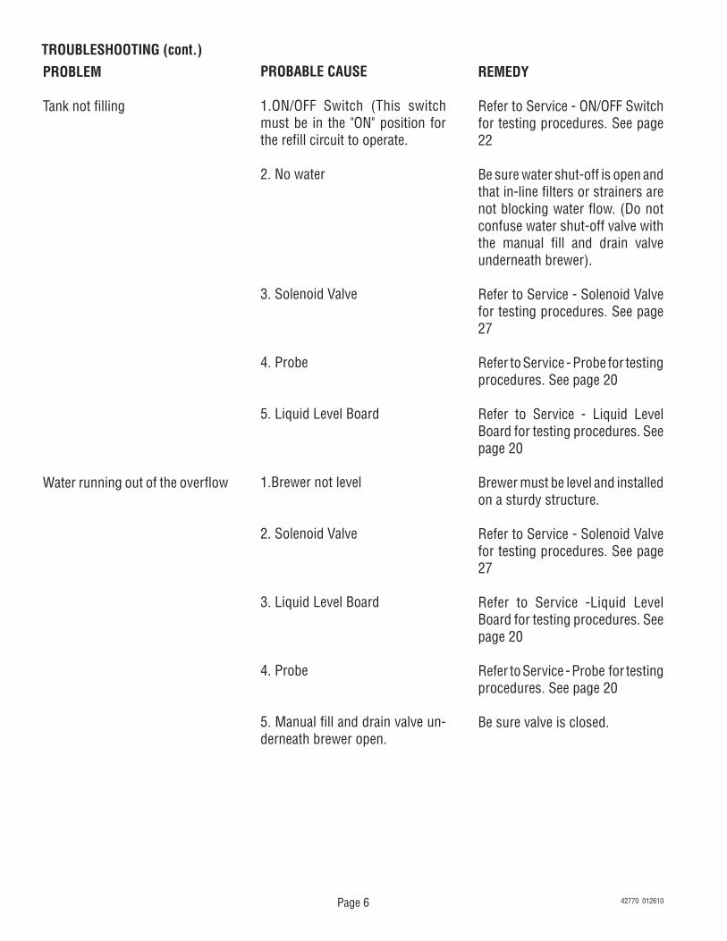
TROUBLESHOOTING (cont.)PROBLEM
Tank not filling
Water running out of the overflow
PROBABLE CAUSE
1.ON/OFF Switch (This switch must be in the "ON" position for the refill circuit to operate.
2. No water
3. Solenoid Valve
4. Probe
5. Liquid Level Board
1.Brewer not level
2. Solenoid Valve
3. Liquid Level Board
4. Probe
5. Manual fill and drain valve un-derneath brewer open.
REMEDY
Refer to Service - ON/OFF Switch for testing procedures. See page 22
Be sure water shut-off is open and that in-line filters or strainers are not blocking water flow. (Do not confuse water shut-off valve with the manual fill and drain valve underneath brewer).
Refer to Service - Solenoid Valve for testing procedures. See page 27
Refer to Service - Probe for testing procedures. See page 20
Refer to Service - Liquid Level Board for testing procedures. See page 20
Brewer must be level and installed on a sturdy structure.
Refer to Service - Solenoid Valve for testing procedures. See page 27
Refer to Service -Liquid Level Board for testing procedures. See page 20
Refer to Service - Probe for testing procedures. See page 20
Be sure valve is closed.
42770 012610
Page 7
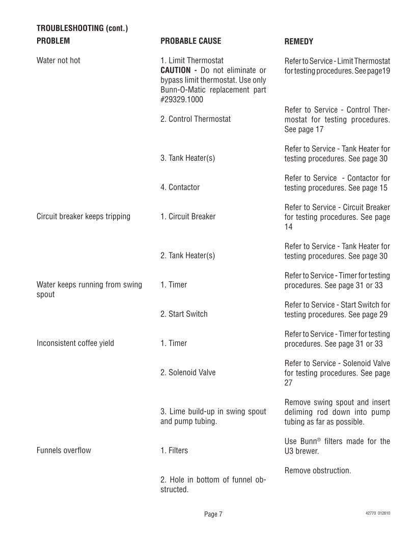
PROBABLE CAUSE
1. Limit ThermostatCAUTION - Do not eliminate or bypass limit thermostat. Use only Bunn-O-Matic replacement part #29329.1000
2. Control Thermostat
3. Tank Heater(s)
4. Contactor
1. Circuit Breaker
2. Tank Heater(s)
1. Timer
2. Start Switch
1. Timer
2. Solenoid Valve
3. Lime build-up in swing spout and pump tubing.
1. Filters
2. Hole in bottom of funnel ob-structed.
TROUBLESHOOTING (cont.)PROBLEM
Water not hot
Circuit breaker keeps tripping
Water keeps running from swing spout
Inconsistent coffee yield
Funnels overflow
REMEDY
Refer to Service - Limit Thermostat for testing procedures. See page19
Refer to Service - Control Ther-mostat for testing procedures. See page 17
Refer to Service - Tank Heater for testing procedures. See page 30
Refer to Service - Contactor for testing procedures. See page 15
Refer to Service - Circuit Breaker for testing procedures. See page 14
Refer to Service - Tank Heater for testing procedures. See page 30
Refer to Service - Timer for testing procedures. See page 31 or 33
Refer to Service - Start Switch for testing procedures. See page 29
Refer to Service - Timer for testing procedures. See page 31 or 33
Refer to Service - Solenoid Valve for testing procedures. See page 27
Remove swing spout and insert deliming rod down into pump tubing as far as possible.
Use Bunn® filters made for the U3 brewer.
Remove obstruction.
42770 012610
Page 8
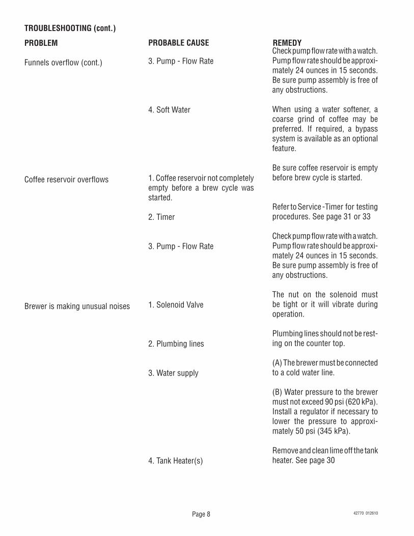
TROUBLESHOOTING (cont.)
PROBLEM
Funnels overflow (cont.)
Coffee reservoir overflows
Brewer is making unusual noises
PROBABLE CAUSE REMEDY
3. Pump - Flow Rate
4. Soft Water
1. Coffee reservoir not completely empty before a brew cycle was started.
2. Timer
3. Pump - Flow Rate
1. Solenoid Valve
2. Plumbing lines
3. Water supply
4. Tank Heater(s)
Check pump flow rate with a watch. Pump flow rate should be approxi-mately 24 ounces in 15 seconds. Be sure pump assembly is free of any obstructions.
When using a water softener, a coarse grind of coffee may be preferred. If required, a bypass system is available as an optional feature.
Be sure coffee reservoir is empty before brew cycle is started.
Refer to Service -Timer for testing procedures. See page 31 or 33
Check pump flow rate with a watch. Pump flow rate should be approxi-mately 24 ounces in 15 seconds. Be sure pump assembly is free of any obstructions.
The nut on the solenoid must be tight or it will vibrate during operation.
Plumbing lines should not be rest-ing on the counter top.
(A) The brewer must be connected to a cold water line.
(B) Water pressure to the brewer must not exceed 90 psi (620 kPa). Install a regulator if necessary to lower the pressure to approxi-mately 50 psi (345 kPa).
Remove and clean lime off the tank heater. See page 30
42770 012610
Page 9
This section provides procedures for testing and replacing various major components used in this brewer should service become necessary. Refer to Troubleshooting for assistance in determining the cause of any problem.
WARNING - Inspection, testing, and repair of electri-cal equipment should be performed only by qualified service personnel. The brewer should be unplugged when servicing, except when electrical tests are re-quired and the test procedure specifically states to plug in the brewer.
COMPONENT ACCESS - U3
WARNING - Disconnect the brewer from the power source before the removal of any panel or the replace-ment of any component.
All components are accessible by the removal of the swing spout, front cupola cover, rear cupola cover and the cupola.
Disconnect the swing spout nut from the swing spout base fitting. Remove swing spout.
Remove the four #8-32 screws, two on the front and rear, securing front and rear cupola covers to the cupola.
Slip cupola off of the component bracket.
FIG. 9a COMPONENT ACCESS
®
TURN OFF WHEN UNATTENDED
To brew, ensure the temperature
gauge is in the BREW zo
ne,
then turn knob to DAY settin
g.
DAY
NIGHT
OFF
P1317.30FIG. 9b COMPONENT ACCESS
P2053.25
COMPONENT ACCESS - SRU
WARNING - Disconnect the brewer from the power source before the removal of any panel or the replace-ment of any component.
The control thermostat, limit thermostat, pump, solenoid valve, liquid level probe and tank heater are accessible by removal of the swing spout, front cupola cover, rear cupola cover and the cupola.
Disconnect the swing spout nut from the swing spout base fitting. Remove swing spout.
Remove the four #8-32 screws, two on each side, securing the side covers to the cupola.
Slip cupola off of the component bracket.
The on/off switch, selector switch, start switch, timer, contactor and liquid level control board are ac-cessible by removal of the front lower panel.
Remove the four #8-32 screws securing the front access panel to the base.
The circuit breaker, fuse and fuse holder are ac-cessible by removal of the rear utility cover.
Remove the six #8-32 screws securing the rear utility cover to the housing.
42770 012610
Page 10
CIRCUIT BREAKER (120/208V and 120/240V Three Wire Models and 440V Four Wire Models)
Location: SRU
The circuit breaker is located on the rear of the urn, behind the rear utility cover.
Test Procedures:1. Disconnect the brewer from the power source.2. Disconnect the black wire from the main harness
from the circuit breaker and the white wire on the
P2209.60
FIG. 10a CIRCUIT BREAKER
J2
SET LOCK
LOCK
SET
TL1
TL2
TL3
TL4
TL5
J1
pump assembly. With a voltmeter, check the voltage across the black wire and the white wire. Connect the brewer to the power source. The indication must be:
a) 120 volts ac for three wire 120/208 volt and 120/240 volt models.
b) 208 or 240 volts ac for four wire 440 volt models.
3. Disconnect the brewer from the power source.
If voltage is present as described, reconnect the white wire to the pump assembly and proceed to #4. If volt-age is not present as described, refer to the Wiring Diagrams and check the brewer wiring harness.
4. With the black wire removed, remove the other black wire from the circuit breaker.
5. Check for continuity across the terminals on the circuit breaker.
If continuity is present as described the circuit breaker is operating properly.If continuity is not present as described, press the reset button and repeat step 5, if continuity is not present as described, replace the circuit breaker. Removal and Replacement:1. Remove wires from the circuit breaker.2. Remove the nut securing the circuit breaker to the
component bracket.3. Remove circuit breaker and discard.4. Install new circuit breaker on component bracket
and secure with nut.5. Refer to Fig. 10c and reconnect the wires.
BLK from Main Harness
BLK from ON/OFF Switch
FIG. 10c CIRCUIT BREAKER TERMINALS P1723
Location: U3
The circuit breaker is located on the right rear of the component bracket.
P2115.30
FIG. 10b CIRCUIT BREAKER
42770 012610
Page 11
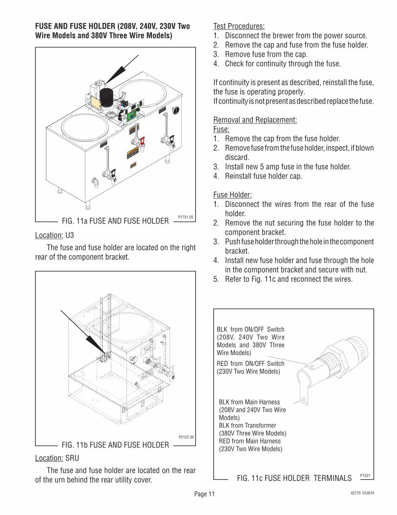
FUSE AND FUSE HOLDER (208V, 240V, 230V Two Wire Models and 380V Three Wire Models)
FIG. 11a FUSE AND FUSE HOLDERP1731.55
Test Procedures:1. Disconnect the brewer from the power source.2. Remove the cap and fuse from the fuse holder.3. Remove fuse from the cap.4. Check for continuity through the fuse.
If continuity is present as described, reinstall the fuse, the fuse is operating properly.If continuity is not present as described replace the fuse.
Removal and Replacement:Fuse:1. Remove the cap from the fuse holder.2. Remove fuse from the fuse holder, inspect, if blown
discard.3. Install new 5 amp fuse in the fuse holder.4. Reinstall fuse holder cap.
Fuse Holder:1. Disconnect the wires from the rear of the fuse
holder.2. Remove the nut securing the fuse holder to the
component bracket.3. Push fuse holder through the hole in the component
bracket.4. Install new fuse holder and fuse through the hole
in the component bracket and secure with nut.5. Refer to Fig. 11c and reconnect the wires.
BLK from ON/OFF Switch (208V, 240V Two Wire Models and 380V Three Wire Models)
RED from ON/OFF Switch (230V Two Wire Models)
FIG. 11c FUSE HOLDER TERMINALS P1331
BLK from Main Harness (208V and 240V Two Wire Models)BLK from Transformer(380V Three Wire Models)RED from Main Harness(230V Two Wire Models)
Location: U3
The fuse and fuse holder are located on the right rear of the component bracket.
FIG. 11b FUSE AND FUSE HOLDERP2122.30
Location: SRU
The fuse and fuse holder are located on the rear of the urn behind the rear utility cover.
42770 012610
Page 12
J2
SET LOCK
LOCK
SET
TL1
TL2
TL3
TL4
TL5
J1
P2209.60FIG. 12a CONTACTOR
CONTACTOR
Location: SRU The contactor is located inside the front lower ac-cess panel, left of center on the component bracket.
Test Procedures:1. Disconnect the brewer from the power source.2A. 120/208V, 120/240V, 380V THREE WIRE MODELS,
380V and 440V FOUR WIRE MODELS Disconnect the black wire from the contactor coil
to the limit thermostat and black wire from the white wire on the main harness.
2B. 208V or 240V TWO WIRE MODELS (Prior to # U300004095), 208V and 240V THREE WIRE MODELS
Disconnect the black wire from the contactor coil to the limit thermostat and black wire from the red wire on the main harness.
2C. 230V MODELS (S/N U300004095 - UP) Disconnect the red wire from contactor coil to the
limit thermostat and the black wire from the main harness.
3. Connect the brewer to the power source. 4. Check the voltage across the coil wire and the wire
from the main harness. The indication must be: a) 120 volts ac for three wire 120/208, 120/240
volt and 380 volt models. b) 230 volts ac for two wire 230 volt models. c) 208 or 240 volts ac for two wire 208 or 240 volt
models. d) 220 or 254 volts ac for four wire 280 or 440
volt models.
5. Disconnect the brewer from the power source.
If voltage is present as described, proceed to #6.If voltage is not present as described refer to the Wir-ing Diagrams and check the brewer wiring harness.
6. Check for continuity between the black leads on the contactor coil or the left and right terminals on the contactor coil on 230V models.
If continuity is present as described, reconnect the wires and proceed to #7.If continuity is not present as described, replace the contactor.
7. On all brewers, with a voltmeter, check the voltage across the upper left terminal and the upper right terminal on the contactor. Connect the brewer to the power source. The indication must be:
a) 120 volts ac for three wire 120/208, 120/240 volt and 380 volt models.
b) 230 volts ac for two wire 230 volt models. c) 208 or 240 volts ac for two wire 208 or 240 volt
models. d) 220 or 254 volts ac for four wire 280 or 440
volt models.8. Disconnect the brewer from the power source.
Location: U3 The contactor is located on the left front of the component bracket.
P2208.40
FIG. 12b CONTACTOR
J2
SET LOCK
LOCK
SET
TL1
TL2
TL3
TL4
TL5
J1
42770 012610
Page 13
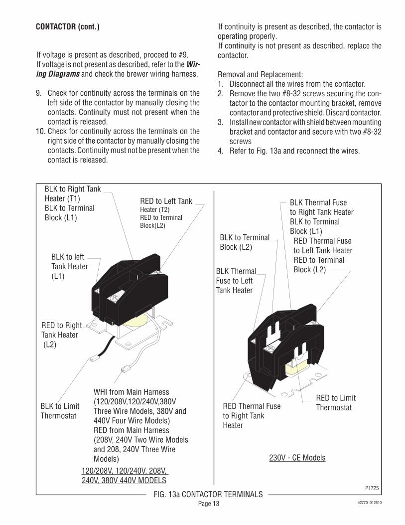
RED to Left TankHeater (T2)RED to TerminalBlock(L2)
BLK Thermal Fuse to Left Tank Heater
BLK to left Tank Heater(L1)
BLK to Right TankHeater (T1)BLK to TerminalBlock (L1)
RED to Right Tank Heater (L2)
WHI from Main Harness(120/208V,120/240V,380V Three Wire Models, 380V and440V Four Wire Models)RED from Main Harness(208V, 240V Two Wire Modelsand 208, 240V Three Wire Models)
RED to Limit Thermostat
RED Thermal Fuse to Left Tank HeaterRED to Terminal Block (L2)
BLK to Terminal Block (L2)
RED Thermal Fuseto Right Tank Heater
BLK Thermal Fuse to Right Tank HeaterBLK to Terminal Block (L1)
120/208V, 120/240V, 208V, 240V, 380V 440V MODELS
230V - CE Models
P1725FIG. 13a CONTACTOR TERMINALS
CONTACTOR (cont.)
If voltage is present as described, proceed to #9.If voltage is not present as described, refer to the Wir-ing Diagrams and check the brewer wiring harness.
9. Check for continuity across the terminals on the left side of the contactor by manually closing the contacts. Continuity must not present when the contact is released.
10. Check for continuity across the terminals on the right side of the contactor by manually closing the contacts. Continuity must not be present when the contact is released.
If continuity is present as described, the contactor is operating properly.If continuity is not present as described, replace the contactor.
Removal and Replacement:1. Disconnect all the wires from the contactor.2. Remove the two #8-32 screws securing the con-
tactor to the contactor mounting bracket, remove contactor and protective shield. Discard contactor.
3. Install new contactor with shield between mounting bracket and contactor and secure with two #8-32 screws
4. Disconnect the brewer from the power source.If voltage is present as described, proceed to #5.If voltage is not present as described, refer to the Wir-ing Diagrams and check the brewer wiring harness.
5. Disconnect the black wires from the control ther-mostat.
6. Check for continuity across the terminals on the control thermostat with the control thermostat in the "ON" position (fully clockwise), continuity must not be present when the thermostat is in the "OFF" position (fully counterclockwise).
If continuity is present as described, the control ther-mostat is operating properly.If continuity is not present as described, replace the control thermostat.
Removal and Replacement:1. Disconnect the wires from the control thermostat.2. Remove the thermostat capillary bulb by firmly
pulling up on the capillary at the component bracket. This will disengage the grommet from the component bracket.
3. Remove the #8-32 screw securing the control thermostat and mounting bracket to the component bracket. Remove control thermostat and bracket as an assembly.
4. Remove knob from control thermostat.5. Remove the two #6-32 screws securing the control
thermostat to the thermostat mounting bracket. Remove and discard thermostat.
6. Install new control thermostat on thermostat mounting bracket and secure with two #6-32 screw.
7. Install knob on thermostat.
Check Voltage AcrossBlack wire on thermostat from main harness to white wire in terminal block.
Red wire on thermostat from main harness to black wire in terminal block.
Black wire on thermostat from main harness to red wire in the terminal block.
Black wire on thermostat from main harness to white wire in terminal block.
Black wire on thermostat from main harness to white wire on step down trans-former.
Voltage120V
230V
208V or240V
220V or254V
120V
FIG. 14b CONTROL THERMOSTATP2113.40
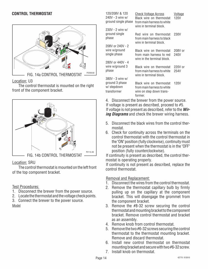
Location: U3 The control thermostat is mounted on the right front of the component bracket.
Location: SRU The control thermostat is mounted on the left front of the top component bracket.
Test Procedures:1. Disconnect the brewer from the power source.2. Locate the thermostat and the voltage check points.3. Connect the brewer to the power source.Model
42770 012610
Page 15
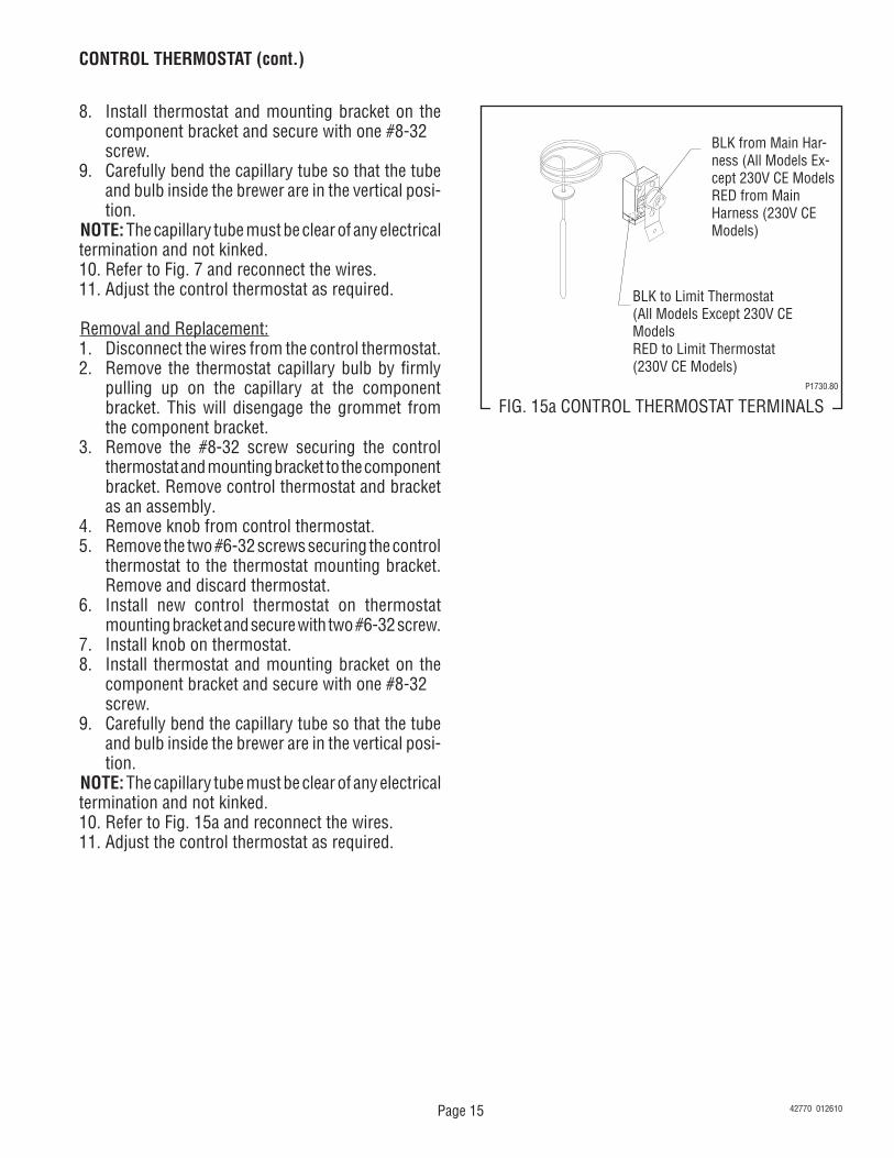
BLK from Main Har-ness (All Models Ex-cept 230V CE ModelsRED from Main Harness (230V CE Models)
BLK to Limit Thermostat (All Models Except 230V CE ModelsRED to Limit Thermostat (230V CE Models)
P1730.80
FIG. 15a CONTROL THERMOSTAT TERMINALS
8. Install thermostat and mounting bracket on the component bracket and secure with one #8-32
screw.9. Carefully bend the capillary tube so that the tube
and bulb inside the brewer are in the vertical posi-tion.
NOTE: The capillary tube must be clear of any electrical termination and not kinked.10. Refer to Fig. 7 and reconnect the wires.11. Adjust the control thermostat as required.
Removal and Replacement:1. Disconnect the wires from the control thermostat.2. Remove the thermostat capillary bulb by firmly
pulling up on the capillary at the component bracket. This will disengage the grommet from the component bracket.
3. Remove the #8-32 screw securing the control thermostat and mounting bracket to the component bracket. Remove control thermostat and bracket as an assembly.
4. Remove knob from control thermostat.5. Remove the two #6-32 screws securing the control
thermostat to the thermostat mounting bracket. Remove and discard thermostat.
6. Install new control thermostat on thermostat mounting bracket and secure with two #6-32 screw.
7. Install knob on thermostat.8. Install thermostat and mounting bracket on the
component bracket and secure with one #8-32 screw.9. Carefully bend the capillary tube so that the tube
and bulb inside the brewer are in the vertical posi-tion.
NOTE: The capillary tube must be clear of any electrical termination and not kinked.10. Refer to Fig. 15a and reconnect the wires.11. Adjust the control thermostat as required.
CONTROL THERMOSTAT (cont.)
42770 012610
Page 16
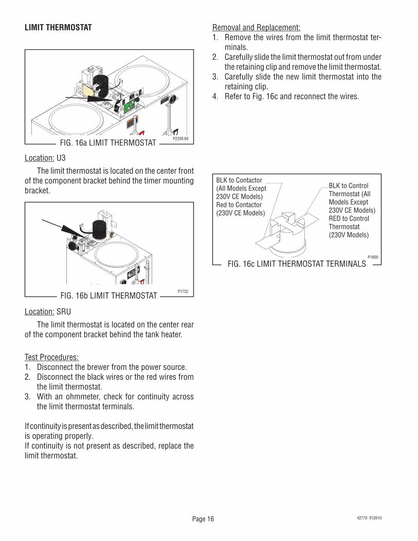
LIMIT THERMOSTAT
J2
SET LOCK
LOCK
SET
TL1
TL2
TL3
TL4
TL5
J1
FIG. 16c LIMIT THERMOSTAT TERMINALS
FIG. 16a LIMIT THERMOSTATP2209.60
Location: SRU
The limit thermostat is located on the center rear of the component bracket behind the tank heater.
Test Procedures:1. Disconnect the brewer from the power source.2. Disconnect the black wires or the red wires from
the limit thermostat.3. With an ohmmeter, check for continuity across
the limit thermostat terminals.
If continuity is present as described, the limit thermostat is operating properly.If continuity is not present as described, replace the limit thermostat.
BLK to Control Thermostat (All Models Except 230V CE Models)RED to Control Thermostat (230V Models)
Removal and Replacement:1. Remove the wires from the limit thermostat ter-
minals.2. Carefully slide the limit thermostat out from under
the retaining clip and remove the limit thermostat.3. Carefully slide the new limit thermostat into the
retaining clip.4. Refer to Fig. 16c and reconnect the wires.
BLK to Contactor (All Models Except 230V CE Models)Red to Contactor (230V CE Models)
FIG. 16b LIMIT THERMOSTATP1732
Location: U3
The limit thermostat is located on the center front of the component bracket behind the timer mounting bracket.
42770 012610
P1800
Page 17
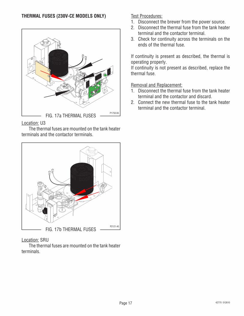
THERMAL FUSES (230V-CE MODELS ONLY)
J2
SET LOCK
LOCK
SET
TL1
TL2
TL3
TL4
TL5
J1
FIG. 17a THERMAL FUSESP1750.65
Test Procedures:1. Disconnect the brewer from the power source.2. Disconnect the thermal fuse from the tank heater
terminal and the contactor terminal.3. Check for continuity across the terminals on the
ends of the thermal fuse.
If continuity is present as described, the thermal is operating properly.If continuity is not present as described, replace the thermal fuse.
Removal and Replacement:1. Disconnect the thermal fuse from the tank heater
terminal and the contactor and discard.2. Connect the new thermal fuse to the tank heater
terminal and the contactor terminal.
Location: U3The thermal fuses are mounted on the tank heater
terminals and the contactor terminals.
FIG. 17b THERMAL FUSESP2121.40
Location: SRUThe thermal fuses are mounted on the tank heater
terminals.
42770 012610
Page 18
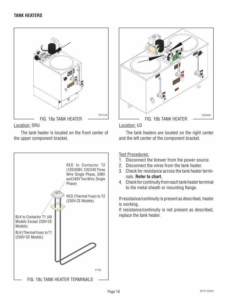
TANK HEATERS
J2
SET LOCK
LOCK
SET
TL1
TL2
TL3
TL4
TL5
J1
FIG. 18b TANK HEATERP2209.60
Test Procedures:1. Disconnect the brewer from the power source.2. Disconnect the wires from the tank heater.3. Check for resistance across the tank heater termi-
nals. Refer to chart.4. Check for continuity from each tank heater terminal
to the metal sheath or mounting flange.
If resistance/continuity is present as described, heater is working.If resistance/continuity is not present as described, replace the tank heater.
Location: U3
The tank heaters are located on the right center and the left center of the component bracket.
FIG. 18a TANK HEATERP2113.40
Location: SRU
The tank heater is located on the front center of the upper component bracket.
BLK to Contactor T1 (All Models Except 230V-CE Models)
BLK (Thermal Fuse) to T1 (230V-CE Models)
RED to Contactor T2 (120/208V, 120/240 Three Wire Single Phase, 208V and 240V Two Wire, Single Phase)
RED (Thermal Fuse) to T2 (230V-CE Models)
P1746
FIG. 18c TANK HEATER TERMINALS
42770 012610
Page 19
TANK HEATERS (cont.)
BLK to Contactor T1 (All Models Except 230V-CE Models)
BLK (Thermal Fuse) to Contactor Top Left Ter-minal) (230V-CE Models)
RED to Contactor T2 (All Models Except 230V-CE Models)
RED (Thermal Fuse) to Con-tactor Top Right Terminal) (230V-CE Models)
BLK to Contactor L1 (120/208V, 120/240 Three Wire Single Phase, 208V and 240V Two Wire, Single Phase)
BLU to Main Harness (208V, 240V, 380V Three Wire ,Three Phase and 380V,440V Four Wire, Three Phase
BLK (Thermal Fuse to Contactor Lower Left Ter-minal) (230V-CE Models)
RED to Contactor L2 (120/208V, 120/240 Three Wire Single Phase, 208V and 240V Two Wire, Single Phase)
BLU to Main Harness (208V, 240V, 380V Three Wire ,Three Phase and 380V,440V Four Wire, Three Phase
RED (Thermal Fuse) to Contactor Lower Right Terminal)
FIG. 19a TANK HEATER TERMINALSP1746
LEFT RIGHT
Removal and Replacement:1. Remove the wires or thermal fuses from the tank
heater.2. Remove the four #8-32 screws securing the tank
heater to the component bracket.3. Remove tank heater and gasket.4. Position new tank heater and gasket on the com-
ponent bracket and secure with four #8-32 screws.5. Refer to Fig. 18c/19a and reconnect the wires.
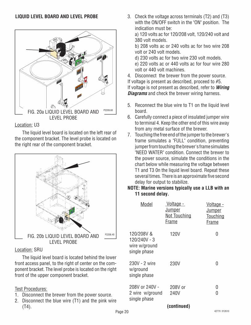
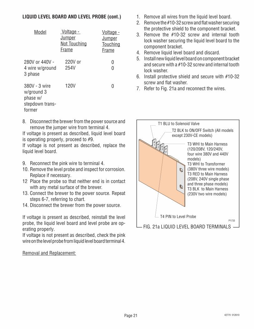
The liquid level board is located behind the lower front access panel, to the right of center on the com-ponent bracket. The level probe is located on the right front of the upper component bracket.
Test Procedures:1. Disconnect the brewer from the power source.2. Disconnect the blue wire (T1) and the pink wire
(T4).
3. Check the voltage across terminals (T2) and (T3) with the ON/OFF switch in the "ON" position. The indication must be:
a) 120 volts ac for 120/208 volt, 120/240 volt and 380 volt models.
b) 208 volts ac or 240 volts ac for two wire 208 volt or 240 volt models.
d) 230 volts ac for two wire 230 volt models. e) 220 volts ac or 440 volts ac for four wire 280
volt or 440 volt machines.4. Disconnect the brewer from the power source.If voltage is present as described, proceed to #5.If voltage is not present as described, refer to Wiring Diagrams and check the brewer wiring harness.
5. Reconnect the blue wire to T1 on the liquid level board.
6. Carefully connect a piece of insulated jumper wire to terminal 4. Keep the other end of this wire away from any metal surface of the brewer.
7. Touching the free end of the jumper to the brewer's frame simulates a "FULL" condition, preventing jumper from touching the brewer's frame simulates "NEED WATER" condition. Connect the brewer to the power source, simulate the conditions in the chart below while measuring the voltage between T1 and T3 0n the liquid level board. Repeat these several times. There is an approximate five second delay for output to stabilize.
NOTE: Marine versions typically use a LLB with an 11 second delay.
Voltage - JumperNot TouchingFrame
120V
230V
208V or240V
Model
120/208V &120/240V - 3wire w/groundsingle phase
230V - 2 wirew/groundsingle phase
208V or 240V -2 wire w/groundsingle phase
Voltage -JumperTouchingFrame
0
0
00
Location: U3
The liquid level board is located on the left rear of the component bracket. The level probe is located on the right rear of the component bracket.
FIG. 20b LIQUID LEVEL BOARD AND LEVEL PROBE
P2208.40
J2
SET LOCK
LOCK
SET
TL1
TL2
TL3
TL4
TL5
J1
(continued)42770 012610
Page 21
LIQUID LEVEL BOARD AND LEVEL PROBE (cont.)
T1 BLU to Solenoid Valve
T2 BLK to ON/OFF Switch (All models except 230V-CE models)
T3 WHI to Main Harness(120/208V, 120/240V, four wire 380V and 440V models)T3 WHI to Transformer (380V three wire models)T3 RED to Main Harness(208V, 240V single phase and three phase models)T3 BLK to Main Harness(230V two wire models)
T4 PIN to Level Probe
FIG. 21a LIQUID LEVEL BOARD TERMINALSP1733
8. Disconnect the brewer from the power source and remove the jumper wire from terminal 4.
If voltage is present as described, liquid level board is operating properly, proceed to #9.If voltage is not present as described, replace the liquid level board.
9. Reconnect the pink wire to terminal 4.10. Remove the level probe and inspect for corrosion.
Replace if necessary.12 Place the probe so that neither end is in contact
with any metal surface of the brewer.13. Connect the brewer to the power source. Repeat
steps 6-7, referring to chart.14. Disconnect the brewer from the power source.
If voltage is present as described, reinstall the level probe, the liquid level board and level probe are op-erating properly.If voltage is not present as described, check the pink wire on the level probe from liquid level board terminal 4.
Removal and Replacement:
1. Remove all wires from the liquid level board.2. Remove the #10-32 screw and flat washer securing
the protective shield to the component bracket.3. Remove the #10-32 screw and internal tooth
lock washer securing the liquid level board to the component bracket.
4. Remove liquid level board and discard.5. Install new liquid level board on component bracket
and secure with a #10-32 screw and internal tooth lock washer.
6. Install protective shield and secure with #10-32 screw and flat washer.
Location: SRU The timer is located inside the front of the trunk on the top of the component bracket.
Test Procedure.NOTE: Do not remove or install wires while timer board is installed. Pressure applied to one side may cause damage to the board.1. Disconnect the brewer from the power source.2. With a voltmeter, check the voltage across terminals
TL1 and TL2 when the "ON/OFF" switch is in the
"ON" position. Connect the brewer to the power source. The indication must be:
a) 120 volts ac for three wire 120/208 volt , 120/240 volt and 380 volt models.
b) 208 volts ac for two wire 208 volt models. c) 240 volts ac for two wire 240 volt models. d) 230 volts ac for two wire 230 volt CE models. e) 208 or 240 volts ac for four wire 440 volt models. 3. Disconnect the brewer from the power source.
If voltage is present as described, proceed to #4.If voltage is not present as described, refer to the Wir-ing Diagrams and check the brewer wiring harness.
4. With a voltmeter, check the voltage across terminals TL1 and TL4 when the "ON/OFF" switch is in the "ON" position. Connect the brewer to the power source. The indication must be 0 volts.
If voltage is as described, proceed to #5.If voltage is not as described, disconnect the brewer from the power source and replace the timer.
5. With a voltmeter, check the voltage across ter-minals TL1 and TL4 when the "ON/OFF" switch is in the "ON" position. Connect the brewer to the power source and press the "START" switch. The indication must be as follows:
a) 120 volts ac for three wire 120/208 volt, 120/240 volt and 380 volt models.
b) 208 volts ac for two wire 208 volt models. c) 240 volts ac for two wire 240 volt models. d) 230 volts ac for two wire 230 volt CE models. e) 208 or 240 volts ac for four wire 440 volt models.
If voltage is present as described, the brew timer is operating properly.If voltage is not present as described, disconnect the brewer from the power source and replace the timer.
Removal and Replacement:1. Remove the two #8-32 screws securing circuit
board to the mounting bracket.2. Remove circuit board and spacers (as required).3. Remove all wires from the timer.4. Attach all wires to the replacement timer board
prior to installation to the component mounting bracket. Refer to FIG. 23a when reconnecting the wires.
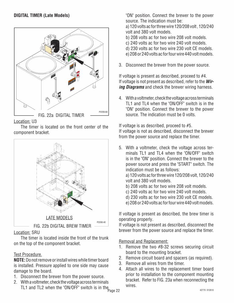
Location: U3 The timer is located on the front center of the component bracket.
J2
SET LOCK
LOCK
SET
TL1
TL2
TL3
TL4
TL5
J1
FIG. 22b DIGITAL BREW TIMERP2208.40
LATE MODELS
42770 012610
Page 23
DIGITAL TIMER (Late Models)
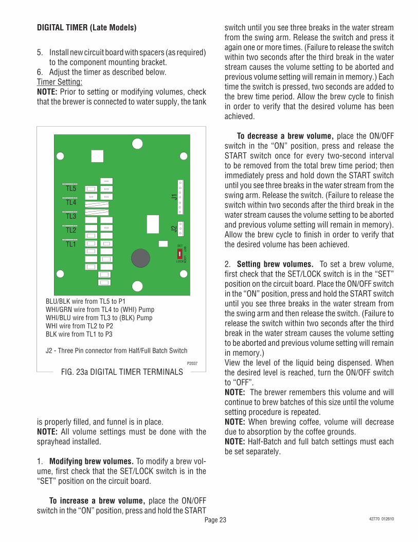
BLU/BLK wire from TL5 to P1WHI/GRN wire from TL4 to (WHI) PumpWHI/BLU wire from TL3 to (BLK) PumpWHI wire from TL2 to P2BLK wire from TL1 to P3
J2 - Three Pin connector from Half/Full Batch Switch
P2037
FIG. 23a DIGITAL TIMER TERMINALS
5. Install new circuit board with spacers (as required) to the component mounting bracket.
6. Adjust the timer as described below.Timer Setting:NOTE: Prior to setting or modifying volumes, check that the brewer is connected to water supply, the tank
switch until you see three breaks in the water stream from the swing arm. Release the switch and press it again one or more times. (Failure to release the switch within two seconds after the third break in the water stream causes the volume setting to be aborted and previous volume setting will remain in memory.) Each time the switch is pressed, two seconds are added to the brew time period. Allow the brew cycle to finish in order to verify that the desired volume has been achieved.
To decrease a brew volume, place the ON/OFF switch in the “ON” position, press and release the START switch once for every two-second interval to be removed from the total brew time period; then immediately press and hold down the START switch until you see three breaks in the water stream from the swing arm. Release the switch. (Failure to release the switch within two seconds after the third break in the water stream causes the volume setting to be aborted and previous volume setting will remain in memory). Allow the brew cycle to finish in order to verify that the desired volume has been achieved.
2. Setting brew volumes. To set a brew volume, first check that the SET/LOCK switch is in the “SET” position on the circuit board. Place the ON/OFF switch in the “ON” position, press and hold the START switch until you see three breaks in the water stream from the swing arm and then release the switch. (Failure to release the switch within two seconds after the third break in the water stream causes the volume setting to be aborted and previous volume setting will remain in memory.)View the level of the liquid being dispensed. When the desired level is reached, turn the ON/OFF switch to “OFF”. NOTE: The brewer remembers this volume and will continue to brew batches of this size until the volume setting procedure is repeated.NOTE: When brewing coffee, volume will decrease due to absorption by the coffee grounds.NOTE: Half-Batch and full batch settings must each be set separately.
is properly filled, and funnel is in place.NOTE: All volume settings must be done with the sprayhead installed.
1. Modifying brew volumes. To modify a brew vol-ume, first check that the SET/LOCK switch is in the “SET” position on the circuit board.
To increase a brew volume, place the ON/OFF switch in the “ON” position, press and hold the START
42770 012610
Page 24
TIMER (Early Models)
FIG. 24a TIMERP1722.55
Location: U3
The timer is located behind the front access panel on the right side of the component bracket.
Test Procedures:1. Disconnect the brewer from the power source.2. Disconnect the polarized, three pin connector from
the brewer main harness and rotate the brew timer
dial fully counterclockwise.3. With a voltmeter, check the voltage across sockets
P2 and P3 (white and black wire or red wire) of the female connector on the main wiring harness when the "ON/OFF" switch is in the "ON" (upper) position. Connect the brewer to the power source. The indication must be:
a) 120 volts ac for three wire 120/208 volt, 120/240 volt, 380 volt models and 208 or 240 volts ac for four wire 440 volt models.
b) 208 volts ac for two and three wire 208 volt models.
c) 240 volts ac for two and three wire 240 volt models.
d) 230 volts ac for two wire 230 volt CE models.4. Disconnect the brewer from the power source.
If voltage is present as described, proceed to #5.If voltage is not present as described, refer to the Wir-ing Diagrams and check the brewer wiring harness.
5. With a voltmeter, check the voltage across the sockets P1 and P2 (blue and white wires) of the female connector on the main harness when the "ON/OFF" switch is in the "ON" (upper) position and the start switch pressed. Connect the brewer to the power source. The indication must be:
a) 120 volts ac for three wire 120/208 volt, 120/240 volt, 380 volt models and 208 or 240 volt ac for four wire 440 volt models.
b) 208 volts ac for two and three wire 208 volt models.
c) 240 volts ac for two and three wire 240 volt models.
d) 230 volts ac for two wire 230 volt CE models.6. Disconnect the brewer from the power source.7. Reconnect the three pin connector from the main
wiring harness to the connector on the timer.
If voltage is present as described, proceed to #8.If voltage is not present as described, refer to the Wir-ing Diagrams and check the brewer wiring harness.
8. Disconnect the black and white wires to the pump.9. With a voltmeter, check the voltage across the
black and white wires when the "ON/OFF" switch is in the "ON" (upper) position and the start switch pressed to the start position and released. Connect the brewer to the power source. The indication
Location: U3
The timer is located on the front center of the component bracket.
FIG. 24b TIMERP2114.40
42770 012610
Page 25
TIMER (Early Models) (cont.)
must be: a) 120 volts ac for three wire 120/208 volt, 120/240
volt, 380 volt and 208 or 240 volt ac for four wire 440 volt models.
b) 208 volts ac for two and three wire 208 volt models.
c) 240 volts ac for two and three wire 240 volt models.
d) 230 volts ac for two wire 230 volt CE models.
If voltage is present as described, the brew timer is operating properly. Reset the timer dial as required, to obtain the desired brew volume.If voltage is not present as described, replace the timer.
Removal and Replacement:1. Separate all connectors between the brewer wiring
harness and the timer.2. Disconnect the timer leads from the pump leads.3. Remove the two #8-32 screws securing the brew
timer to the component bracket and remove timer.4. Install new timer circuit board as described in
Digital Timer kit instructions.
To Three Pin FemaleConnector on MainHarness
BLK to PumpLead
WHI to Pump Lead
Three Pin Connector from Half/Full Batch Switch
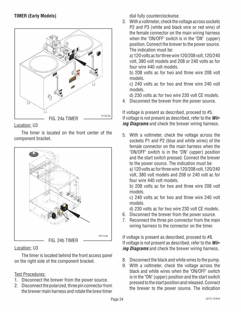
FIG. 25a TIMER TERMINALSP1751
EARLY MODELS
42770 012610
Page 26
PUMP ASSEMBLY
J2
SET LOCK
LOCK
SET
TL1
TL2
TL3
TL4
TL5
J1
FIG. 26a PUMP ASSEMBLYP2209.60
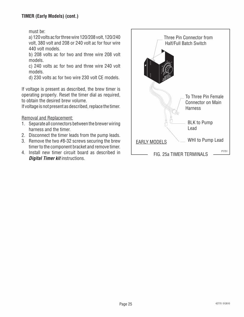
Location: SRU The pump is located on the center rear of the component bracket.
Test Procedures:1. Disconnect the brewer from the power source.2. Disconnect the black wire from the black lead on
the pump and the white wire from the black lead on the pump.
3. With a voltmeter, check the voltage across the black wire and the white wire. Connect the brewer to the power source. The indication must be:
a) 120 vac for three wire 120/208V, 120/240V and 380V models).
b) 208 vac for two or three wire 208V models. c) 240 vac for two or three wire 240V models. d) 230 vac for two wire 230V models. e) 208 or 240 vac for four wire 440V models4. Disconnect the brewer from the power source.
If voltage is present as described, reconnect the wires
to the pump. Install swing spout and position over the reservoir. Place the ON/OFF in the "ON" (upper) position and push the start switch and release. If pump does not run, replace the pump.If voltage is not present as described, refer to the Wir-ing Diagrams and check the brewer wiring harness.
Removal and Replacement (Refer to Fig. 17):1. Disconnect the wires from the pump assembly.2. Loosen the #8-32 screw (2) securing the clamp
(3) on the fill tube (1) and slide the clamp (3) up the fill tube (1).3. Disengage the tube (1) from the pump base (4).4. Remove the four #8-32 screws (6) securing the
pump assembly to the component bracket (7).5. Remove pump assembly (4).6. Remove pump gasket (5) and inspect, replace if
necessary.7. Position gasket (5) on component bracket (7).8. Install new pump assembly on component bracket
(7) and secure with four #8-32 screws (6).9. Install fill tube (1) on pump assembly (4).10. Slide clamp (3) down into position on the fill tube
(1) and tighten screw (2).11. Refer to Fig. 26c and reconnect the wires.
WHI from Brew TimerBLK from Brew Timer
1
2
3
4
5
6
7
FIG. 26c PUMP INSTALLATIONP1737
Location: U3 The pump is located on the center rear of the component bracket.
FIG. 26b PUMP ASSEMBLYP2113.40
42770 012610
Page 27 42770 042319
U3 & SRU Motor/Pump Removal and
Installation Instruction
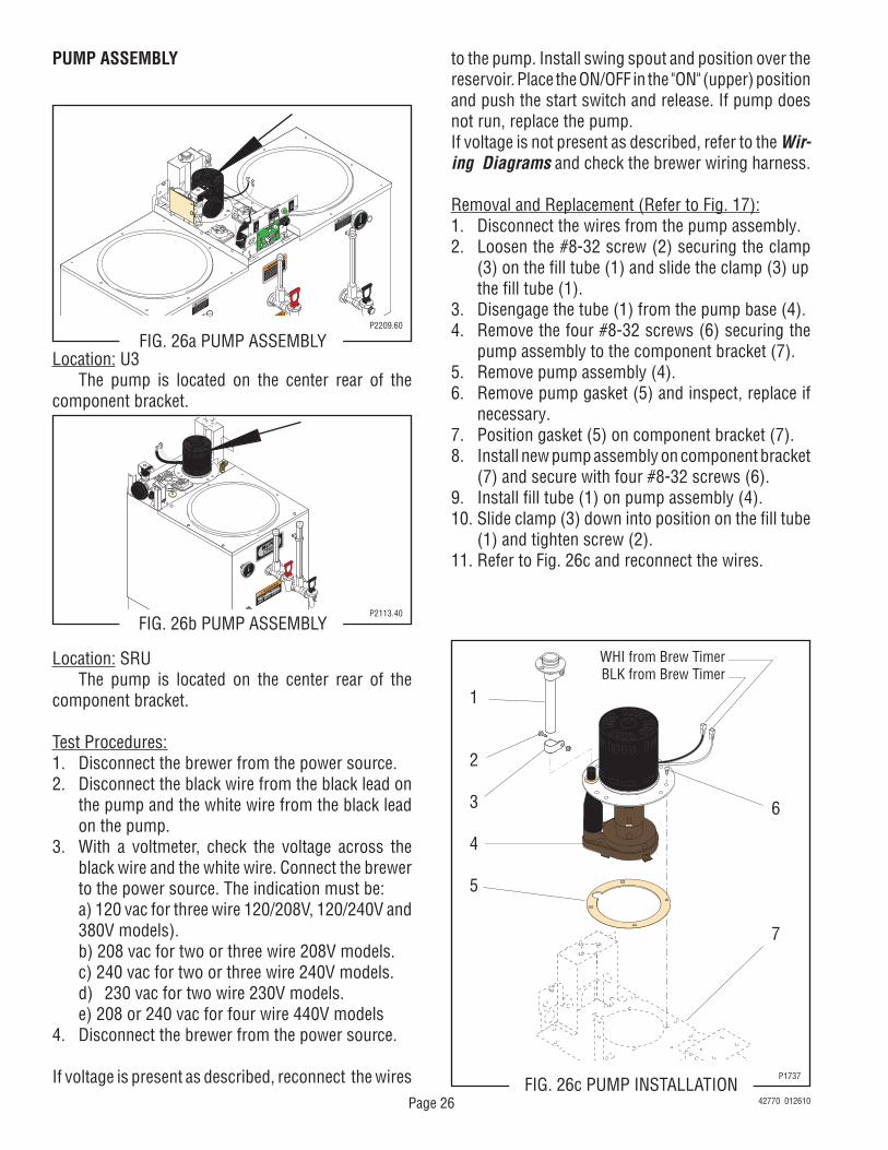
The pump/motor replacement kits include a new outlet tube with a flow restrictor installed within the tube. When you replace the original pump with the new replacement pump, the original outlet tube must be dis-carded and replaced with the new outlet tube with flow restrictor that is included with the new replacement pump.
1. Disconnect machine from power.2. Remove the swing spout and top covers from the brewer.3. Disconnect the pump electrical connection from the main wiring harness.4. Disconnect the silicone tube from the pump and the swing spout base fitting. Discard tube.5. Remove the four screws securing the motor/pump assembly to the component bracket. Remove the motor/pump assembly.5. Install the new motor/pump onto the component bracket and secure with the four screws.6. See Fig.1 - Install the new tube with flow restric-tor to the pump and swing spout base fitting. Secure by using the two clamps and fastening hardware included in the kit.7. Connect the motor/pump electrical wires to the main wiring harness.8. Reinstall the machine top covers and swing spout.9. Reconnect machine to power.10. Adjust batch sizes/volumes by following the in-struction outlined under “Adjusting Brew Volumes”.
Fig. 1
NEW REPLACEMENT PUMP ASSEMBLY APPROXIMATE EFFECTIVE DATE: 03/2018
Page 28
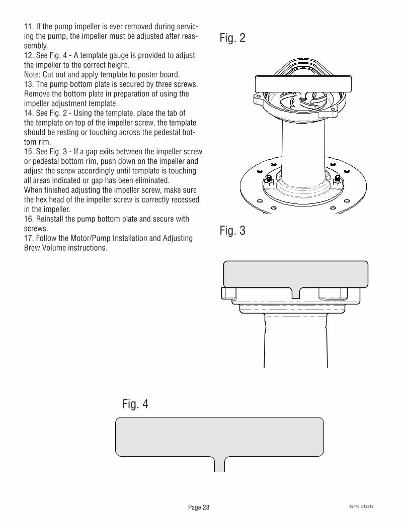
11. If the pump impeller is ever removed during servic-ing the pump, the impeller must be adjusted after reas-sembly.12. See Fig. 4 - A template gauge is provided to adjust the impeller to the correct height.Note: Cut out and apply template to poster board.13. The pump bottom plate is secured by three screws. Remove the bottom plate in preparation of using the impeller adjustment template.14. See Fig. 2 - Using the template, place the tab of the template on top of the impeller screw, the template should be resting or touching across the pedestal bot-tom rim.15. See Fig. 3 - If a gap exits between the impeller screw or pedestal bottom rim, push down on the impeller and adjust the screw accordingly until template is touching all areas indicated or gap has been eliminated.When finished adjusting the impeller screw, make sure the hex head of the impeller screw is correctly recessed in the impeller.16. Reinstall the pump bottom plate and secure with screws.17. Follow the Motor/Pump Installation and Adjusting Brew Volume instructions.
Fig. 2
Fig. 3
Fig. 4
42770 042319
Page 29
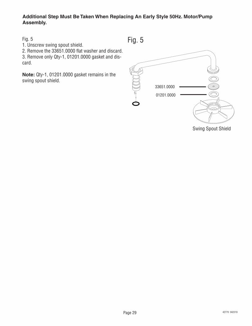
Additional Step Must Be Taken When Replacing An Early Style 50Hz. Motor/PumpAssembly.
Fig. 51. Unscrew swing spout shield.2. Remove the 33651.0000 flat washer and discard.3. Remove only Qty-1, 01201.0000 gasket and dis-card. Note: Qty-1, 01201.0000 gasket remains in the swing spout shield.
Fig. 5
33651.0000
01201.0000
Swing Spout Shield
42770 042319
Page 30
ADJUSTING BREW VOLUMES
CAUTION - Disconnect the power source from the brewer prior to the removal of any panel for the replace-ment or adjustment of any component.NOTE: Prior to setting or modifying batch sizes, check that the brewer is connected to water supply, the tank is properly filled, and a funnel support, funnel and funnel cover are in place.1. Modifying batch sizes. To modify a batch volume, first check that the SET/LOCK switch is in the “SET”
position on the circuit board. To increase a batch size. Press and hold the START or BREW switch until you see three breaks in the
water stream from the swing arm. Release the switch (Failure to release the switch within two seconds after the third break in the water stream causes the volume setting to be aborted and previous volume setting will remain in memory) and press it again one or more times. Each time the switch is pressed, two seconds are added to the brew time period. Allow the brew cycle to finish in order to verify that the desired volume has been achieved.
To decrease a batch size. Press and release the START or BREW switch once for every two-second interval to be removed from the total brew time period; then immediately press and hold down the START or BREW switch until you see three breaks in the water stream from the swing arm. Release the switch. (Failure to release the switch within two seconds after the third break in the water stream causes the volume setting to be aborted and previous volume setting will remain in memory). Allow the brew cycle to finish in order to verify that the desired volume has been achieved.
2. Setting batch sizes. To set a batch volume, first check that the SET/LOCK switch is in the “SET” position on the brew timer circuit board. Press and hold the START or BREW switch until you see three breaks in the water stream from the swing arm, and then release the switch. (Failure to release the switch within two seconds after the third break in the water stream causes the volume setting to be aborted and previous volume setting will remain in memory). View the level of the liquid being dispensed. When the desired level is reached, turn the ON/OFF switch to “OFF” (lower). The brewer remembers this volume and will continue to brew batches of this size until the volume setting procedure is repeated.
NOTE: When brewing coffee, batch volumes will decrease due to absorption by the coffee grounds.NOTE: HALF-BATCH AND FULL BATCH SETTINGS MUST EACH BE SET SEPARATELY.3. Setting programming disable feature. If it becomes necessary to prevent anyone from changing brew
times once programmed, you can set the SET/LOCK switch to the “LOCK” position. This will prevent any programming to be done until switch is once again placed in the “SET” position.
42770 042319
Page 31
RELAY - BREW LOCKOUT OPTION
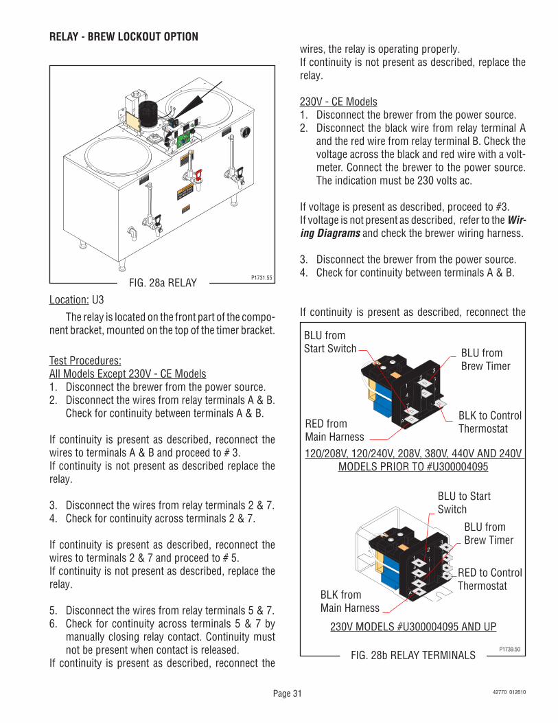
FIG. 28a RELAYP1731.55
Location: U3
The relay is located on the front part of the compo-nent bracket, mounted on the top of the timer bracket.
Test Procedures:All Models Except 230V - CE Models1. Disconnect the brewer from the power source.2. Disconnect the wires from relay terminals A & B.
Check for continuity between terminals A & B.
If continuity is present as described, reconnect the wires to terminals A & B and proceed to # 3.If continuity is not present as described replace the relay.
3. Disconnect the wires from relay terminals 2 & 7.4. Check for continuity across terminals 2 & 7.
If continuity is present as described, reconnect the wires to terminals 2 & 7 and proceed to # 5.If continuity is not present as described, replace the relay.
5. Disconnect the wires from relay terminals 5 & 7.6. Check for continuity across terminals 5 & 7 by
manually closing relay contact. Continuity must not be present when contact is released.
If continuity is present as described, reconnect the
wires, the relay is operating properly.If continuity is not present as described, replace the relay.
230V - CE Models1. Disconnect the brewer from the power source.2. Disconnect the black wire from relay terminal A
and the red wire from relay terminal B. Check the voltage across the black and red wire with a volt-meter. Connect the brewer to the power source. The indication must be 230 volts ac.
If voltage is present as described, proceed to #3.If voltage is not present as described, refer to the Wir-ing Diagrams and check the brewer wiring harness.
3. Disconnect the brewer from the power source.4. Check for continuity between terminals A & B.
If continuity is present as described, reconnect the
6
985
A
14
7
23
B
6
985
A
14
7
23
B
120/208V, 120/240V, 208V, 380V, 440V AND 240V MODELS PRIOR TO #U300004095
230V MODELS #U300004095 AND UP
FIG. 28b RELAY TERMINALSP1739.50
RED fromMain Harness
BLU fromBrew Timer
BLK to ControlThermostat
BLU to StartSwitch
BLU fromBrew Timer
BLK fromMain Harness
RED to ControlThermostat
BLU fromStart Switch
42770 012610
Page 32
RELAY - BREW LOCKOUT OPTION (cont.)
wires to terminals A & B and proceed to #5.If continuity is not present as described, replace the relay.
5. With the thermostat in the "ON" position and the relay engaged disconnect the brewer from the power source.
6. Disconnect the blue wires from relay terminals 1 and 7. Check for continuity across terminals 1 and 7.
If continuity is present as described, proceed to #7If continuity is not present as described, replace the relay. 7. Turn the thermostat to the "OFF" position, con-
nect the brewer to the power source and turn the thermostat back to the "ON" position. Continuity should not be present across terminals 1 & 7.
If continuity is not present as described, the relay is operating properly.If continuity is present as described, replace the relay.
Removal and Replacement:1. Disconnect the wires from the relay.2. For 120/208V, 120/240V, 208V, 380V, 440V and
240V models prior to #U300004095 remove the #6-32 screw securing the relay to the relay mount-ing bracket. For 230V models #U300004095 and up, remove the two screws securing the relay to the relay mounting bracket.
3. Remove relay and discard.4. For 120/208V,120/240V, 208V, 380V, 440V and
240V models prior to #U300004095, install new relay on relay mounting bracket and secure with a #6-32 screw. For 230V models #U300004095 and up, install new relay on relay mounting bracket and secure with two #6-32 screws.
5. Refer to Fig. 28b and reconnect the wires.
42770 012610
Page 33
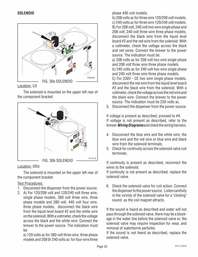
SOLENOID
J2
SET LOCK
LOCK
SET
TL1
TL2
TL3
TL4
TL5
J1
FIG. 30a SOLENOIDP2209.60
Location: SRU
The solenoid is mounted on the upper left rear of the component bracket.
Test Procedures:1. Disconnect the dispenser from the power source.2. A) For 120/208 volt and 120/240 volt three wire,
single phase models, 380 volt three wire, three phase models and 380 volt, 440 volt four wire, three phase models, disconnect the black wire from the liquid level board #2 and the white wire on the solenoid. With a voltmeter, check the voltage across the black and the white wire. Connect the brewer to the power source. The indication must be:
a) 120 volts ac for 380 volt three wire, three phase models and 208 0r 240 volts ac for four wire three
phase 440 volt models. b) 208 volts ac for three wire 120/208 volt models. c) 240 volts ac for three wire 120/240 volt models. B) For 208 volt, 240 volt two wire single phase and
208 volt, 240 volt three wire three phase models, disconnect the black wire from the liquid level board #2 and the red wire from the solenoid. With a voltmeter, check the voltage across the black and red wires. Connect the brewer to the power source. The indication must be:
a) 208 volts ac for 208 volt two wire single phase and 208 volt three wire three phase models.
b) 240 volts ac for 240 volt two wire single phase and 240 volt three wire three phase models.
C) For 230V - CE two wire single phase models, disconnect the red wire from the liquid level board #2 and the black wire from the solenoid. With a voltmeter, check the voltage across the red wire and the black wire. Connect the brewer to the power source. The indication must be 230 volts ac.
3. Disconnect the dispenser from the power source.
If voltage is present as described, proceed to #4.If voltage is not present as described, refer to the brewer Wiring Diagrams and check the wiring harness.
4. Disconnect the blue wire and the white wire, the blue wire and the red wire or blue wire and black wire from the solenoid terminals.
5. Check for continuity across the solenoid valve coil terminals.
If continuity is present as described, reconnect the wires to the solenoid.If continuity is not present as described, replace the solenoid valve.
6. Check the solenoid valve for coil action. Connect the dispenser to the power source. Listen carefully in the vicinity of the solenoid valve for a "clicking" sound as the coil magnet attracts.
If the sound is heard as described and water will not pass through the solenoid valve, there may be a block-age in the water line before the solenoid valve or, the solenoid valve may require inspection for wear, and removal of waterborne particles.If the sound is not heard as described, replace the solenoid valve.
Location: U3
The solenoid is mounted on the upper left rear of the component bracket.
FIG. 30b SOLENOIDP2113.40
42770 012610
Page 34
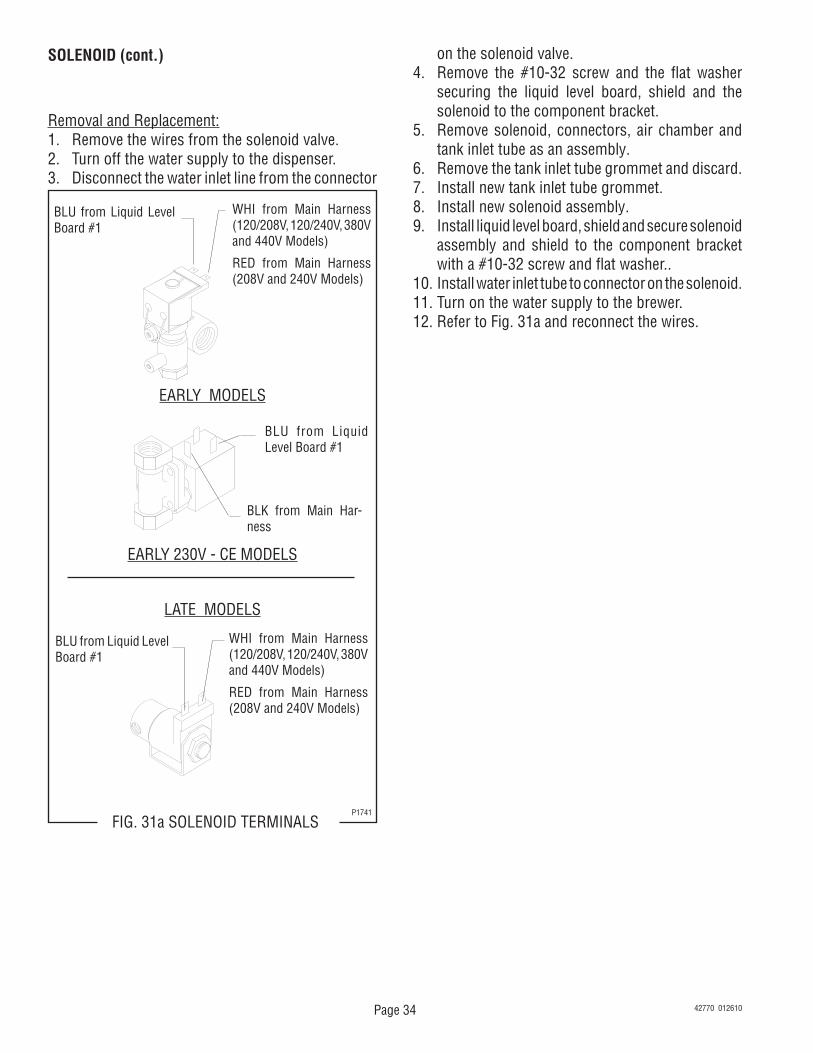
SOLENOID (cont.)
Removal and Replacement:1. Remove the wires from the solenoid valve.2. Turn off the water supply to the dispenser.3. Disconnect the water inlet line from the connector
BLU from Liquid Level Board #1
WHI from Main Harness (120/208V, 120/240V, 380V and 440V Models)
RED from Main Harness (208V and 240V Models)
BLK from Main Har-ness
BLU from Liquid Level Board #1
EARLY 230V - CE MODELS
FIG. 31a SOLENOID TERMINALSP1741
BLU from Liquid Level Board #1
WHI from Main Harness (120/208V, 120/240V, 380V and 440V Models)
RED from Main Harness (208V and 240V Models)
EARLY MODELS
LATE MODELS
on the solenoid valve.4. Remove the #10-32 screw and the flat washer
securing the liquid level board, shield and the solenoid to the component bracket.
5. Remove solenoid, connectors, air chamber and tank inlet tube as an assembly.
6. Remove the tank inlet tube grommet and discard.7. Install new tank inlet tube grommet.8. Install new solenoid assembly.9. Install liquid level board, shield and secure solenoid
assembly and shield to the component bracket with a #10-32 screw and flat washer..
10. Install water inlet tube to connector on the solenoid.11. Turn on the water supply to the brewer.12. Refer to Fig. 31a and reconnect the wires.
42770 012610
Page 35
BLK from Terminal Block
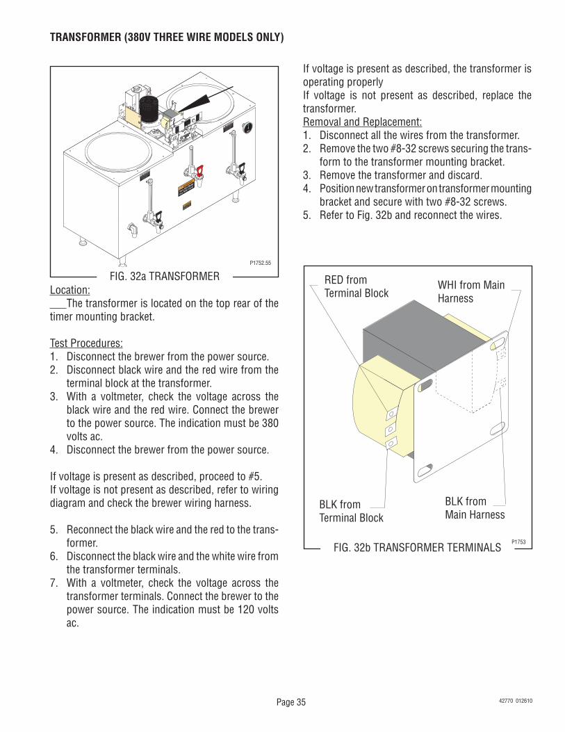
TRANSFORMER (380V THREE WIRE MODELS ONLY)
FIG. 32a TRANSFORMERP1752.55
Location: The transformer is located on the top rear of the timer mounting bracket.
Test Procedures:1. Disconnect the brewer from the power source.2. Disconnect black wire and the red wire from the
terminal block at the transformer.3. With a voltmeter, check the voltage across the
black wire and the red wire. Connect the brewer to the power source. The indication must be 380 volts ac.
4. Disconnect the brewer from the power source.
If voltage is present as described, proceed to #5.If voltage is not present as described, refer to wiring diagram and check the brewer wiring harness.
5. Reconnect the black wire and the red to the trans-former.
6. Disconnect the black wire and the white wire from the transformer terminals.
7. With a voltmeter, check the voltage across the transformer terminals. Connect the brewer to the power source. The indication must be 120 volts ac.
If voltage is present as described, the transformer is operating properlyIf voltage is not present as described, replace the transformer.Removal and Replacement:1. Disconnect all the wires from the transformer.2. Remove the two #8-32 screws securing the trans-
form to the transformer mounting bracket.3. Remove the transformer and discard.4. Position new transformer on transformer mounting
bracket and secure with two #8-32 screws.5. Refer to Fig. 32b and reconnect the wires.
RED from Terminal Block
WHI from Main Harness
BLK from Main Harness
FIG. 32b TRANSFORMER TERMINALSP1753
42770 012610
Page 36
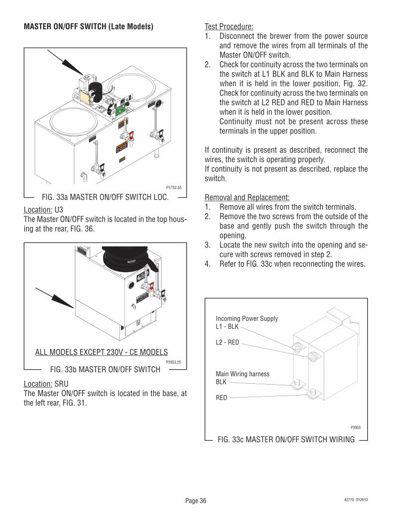
MASTER ON/OFF SWITCH (Late Models)
FIG. 33c MASTER ON/OFF SWITCH WIRING
Location: SRUThe Master ON/OFF switch is located in the base, at the left rear, FIG. 31.
Test Procedure:1. Disconnect the brewer from the power source
and remove the wires from all terminals of the Master ON/OFF switch.
2. Check for continuity across the two terminals on the switch at L1 BLK and BLK to Main Harness when it is held in the lower position, Fig. 32. Check for continuity across the two terminals on the switch at L2 RED and RED to Main Harness when it is held in the lower position.
Continuity must not be present across these terminals in the upper position.
If continuity is present as described, reconnect the wires, the switch is operating properly.If continuity is not present as described, replace the switch.
Removal and Replacement:1. Remove all wires from the switch terminals.2. Remove the two screws from the outside of the
base and gently push the switch through the opening.
3. Locate the new switch into the opening and se-cure with screws removed in step 2.
4. Refer to FIG. 33c when reconnecting the wires.
Incoming Power SupplyL1 - BLK
L2 - RED
Main Wiring harnessBLK
RED
P3955
J2
SET LOCK
LOC
K
SET
TL1
TL2
TL3
TL4
TL5
J1
FIG. 33a MASTER ON/OFF SWITCH LOC.P1752.55
Location: U3The Master ON/OFF switch is located in the top hous-ing at the rear, FIG. 36.
FIG. 33b MASTER ON/OFF SWITCHP2053.25
ALL MODELS EXCEPT 230V - CE MODELS
42770 012610
Page 37
wire on the power indicator light.3. Connect the brewer to the power source. With a
voltmeter, check the voltage across the removed wires. The indication must be:
a) 120 volts ac for 120/208 volt, 120/240 volt and 380 volt models.
b) 208 volts ac for two or three wire 208 volt models.
c) 240 volts ac for two wire 240 volt models prior to #U300004095 and three wire 240 volt models.
d) 230 volts ac for two wire 230 volt models #U300004095 and up).
e) 208 or 240 volts ac for four wire 440 volt models.4. Disconnect the brewer from the power source.
If voltage is present as described, reconnect the wires and proceed to #5If voltage is not present as described, refer to the Wir-ing Diagrams and check the brewer wiring harness.
5. Disconnect the wires on the ON/OFF switch.6. a) 120/208V, 120/240V, 208V, 240V, 380V and
440V Models - Check for continuity across the terminals on the rear of the switch with the switch in the "ON" (upper) position. Continuity must not be present when the switch is in the "OFF" (lower) position.
b) 230V - CE Models - Check for continuity across the center terminal (2) and the lower terminal (1) when the switch is in the "ON" (upper) position. Continuity must not present when the switch is in "OFF" (lower) position.
If continuity is present as described, the switch is operating properly.If continuity is not present as described, replace the switch.
Removal and Replacement:1. Remove the wires from the switch terminals.2. Compress the clips on the back side of the switch
mounting bracket and gently push the through the opening.
3. Push the new switch into the opening and spread the clips to hold switch in the mounting bracket.
NOTE: ON 230V - CE models terminal (3) must be on the top.
4. Refer to Fig. 35a and reconnect the wires.
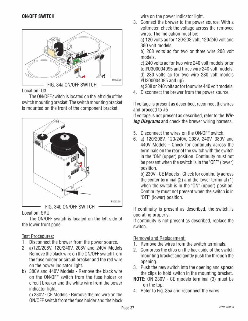
ON/OFF SWITCH
J2
SET LOCK
LOCK
SET
TL1
TL2
TL3
TL4
TL5
J1
FIG. 34a ON/OFF SWITCHP2209.60
Location: SRU The ON/OFF switch is located on the left side of the lower front panel.
Test Procedures:1. Disconnect the brewer from the power source.2. a)120/208V, 120/240V, 208V and 240V Models
Remove the black wire on the ON/OFF switch from the fuse holder or circuit breaker and the red wire on the power indicator light.
b) 380V and 440V Models - Remove the black wire on the ON/OFF switch from the fuse holder or circuit breaker and the white wire from the power indicator light.
c) 230V - CE Models - Remove the red wire on the ON/OFF switch from the fuse holder and the black
Location: U3 The ON/OFF switch is located on the left side of the switch mounting bracket. The switch mounting bracket is mounted on the front of the component bracket.
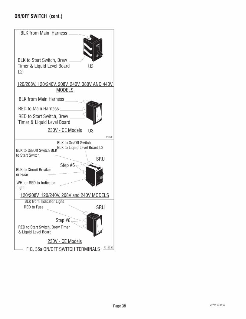
120/208V, 120/240V, 208V, 240V, 380V AND 440V MODELS
BLK from Main Harness
RED to Main Harness
RED to Start Switch, Brew Timer & Liquid Level Board
230V - CE ModelsP1735
BLK to On/Off SwitchBLK to Liquid Level Board L2
120/208V, 120/240V, 208V and 240V MODELSBLK from Indicator LightRED to Fuse
RED to Start Switch, Brew Timer & Liquid Level Board
230V - CE ModelsP2120.50FIG. 35a ON/OFF SWITCH TERMINALS
BLK to On/Off Switch BLK to Start Switch
BLK to Circuit Breaker or Fuse
WHI or RED to Indicator Light
Step #6
Step #6
U3
U3
SRU
SRU
42770 012610
Page 39
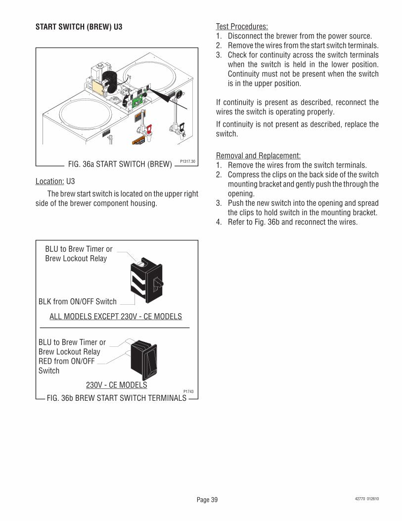
START SWITCH (BREW) U3
J2
SET LOCK
LOCK
SET
TL1
TL2
TL3
TL4
TL5
J1
FIG. 36a START SWITCH (BREW) P1317.30
BLU to Brew Timer or Brew Lockout Relay
BLK from ON/OFF Switch
ALL MODELS EXCEPT 230V - CE MODELS
BLU to Brew Timer orBrew Lockout RelayRED from ON/OFFSwitch
230V - CE MODELS
FIG. 36b BREW START SWITCH TERMINALSP1743
Test Procedures:1. Disconnect the brewer from the power source.2. Remove the wires from the start switch terminals.3. Check for continuity across the switch terminals
when the switch is held in the lower position. Continuity must not be present when the switch is in the upper position.
If continuity is present as described, reconnect the wires the switch is operating properly.
If continuity is not present as described, replace the switch.
Removal and Replacement:1. Remove the wires from the switch terminals.2. Compress the clips on the back side of the switch
mounting bracket and gently push the through the opening.
3. Push the new switch into the opening and spread the clips to hold switch in the mounting bracket.
4. Refer to Fig. 36b and reconnect the wires.
Location: U3
The brew start switch is located on the upper right side of the brewer component housing.
42770 012610
Page 40
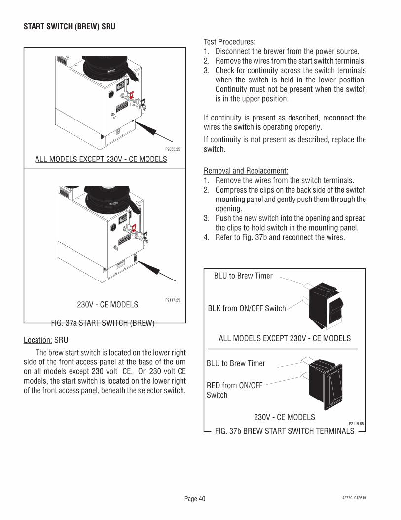
START SWITCH (BREW) SRU
FIG. 37a START SWITCH (BREW)
P2053.25
Location: SRU
The brew start switch is located on the lower right side of the front access panel at the base of the urn on all models except 230 volt CE. On 230 volt CE models, the start switch is located on the lower right of the front access panel, beneath the selector switch.
Test Procedures:1. Disconnect the brewer from the power source.2. Remove the wires from the start switch terminals.3. Check for continuity across the switch terminals
when the switch is held in the lower position. Continuity must not be present when the switch is in the upper position.
If continuity is present as described, reconnect the wires the switch is operating properly.
If continuity is not present as described, replace the switch.
Removal and Replacement:1. Remove the wires from the switch terminals.2. Compress the clips on the back side of the switch
mounting panel and gently push them through the opening.
3. Push the new switch into the opening and spread the clips to hold switch in the mounting panel.
4. Refer to Fig. 37b and reconnect the wires.
BLU to Brew Timer
BLK from ON/OFF Switch
ALL MODELS EXCEPT 230V - CE MODELS
BLU to Brew Timer
RED from ON/OFFSwitch
230V - CE MODELS
FIG. 37b BREW START SWITCH TERMINALSP2119.65
ATTENTION: TURN OFF WHEN UNATTENDED
ATTENTION: TURN OFF WHEN UNATTENDED
ALL MODELS EXCEPT 230V - CE MODELS
230V - CE MODELSP2117.25
42770 012610
Page 41
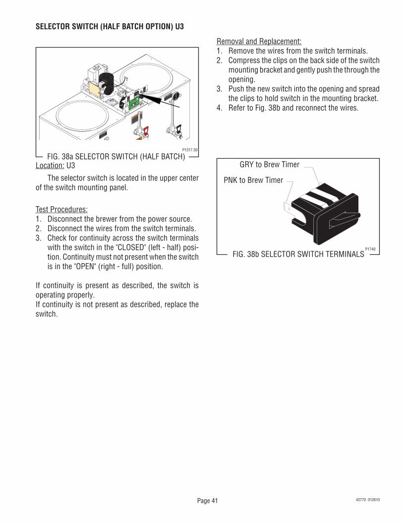
SELECTOR SWITCH (HALF BATCH OPTION) U3
J2
SET LOCK
LOCK
SET
TL1
TL2
TL3
TL4
TL5
J1
FIG. 38a SELECTOR SWITCH (HALF BATCH)Location: U3
The selector switch is located in the upper center of the switch mounting panel.
Test Procedures:1. Disconnect the brewer from the power source.2. Disconnect the wires from the switch terminals.3. Check for continuity across the switch terminals
with the switch in the "CLOSED" (left - half) posi-tion. Continuity must not present when the switch is in the "OPEN" (right - full) position.
If continuity is present as described, the switch is operating properly.If continuity is not present as described, replace the switch.
GRY to Brew Timer
PNK to Brew Timer
FIG. 38b SELECTOR SWITCH TERMINALSP1740
Removal and Replacement:1. Remove the wires from the switch terminals.2. Compress the clips on the back side of the switch
mounting bracket and gently push the through the opening.
3. Push the new switch into the opening and spread the clips to hold switch in the mounting bracket.
4. Refer to Fig. 38b and reconnect the wires.
42770 012610
P1317.30
Page 42
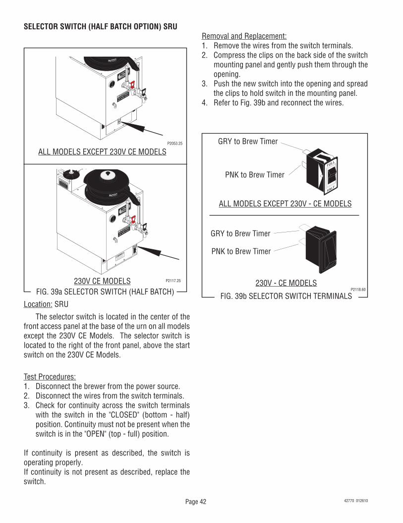
SELECTOR SWITCH (HALF BATCH OPTION) SRU
FIG. 39a SELECTOR SWITCH (HALF BATCH)
P2053.25
Location: SRU
The selector switch is located in the center of the front access panel at the base of the urn on all models except the 230V CE Models. The selector switch is located to the right of the front panel, above the start switch on the 230V CE Models.
Test Procedures:1. Disconnect the brewer from the power source.2. Disconnect the wires from the switch terminals.3. Check for continuity across the switch terminals
with the switch in the "CLOSED" (bottom - half) position. Continuity must not be present when the switch is in the "OPEN" (top - full) position.
If continuity is present as described, the switch is operating properly.If continuity is not present as described, replace the switch.
ALL MODELS EXCEPT 230V CE MODELS
ATTENTION: TURN OFF WHEN UNATTENDED
ATTENTION: TURN OFF WHEN UNATTENDED
230V CE MODELS P2117.25
Removal and Replacement:1. Remove the wires from the switch terminals.2. Compress the clips on the back side of the switch
mounting panel and gently push them through the opening.
3. Push the new switch into the opening and spread the clips to hold switch in the mounting panel.