148
Gearmotors \ Industrial Gear Units \ Drive Electronics \ Drive Automation \ Services MOVIDRIVE ® compact C atalog DA410000 Edition 11/2006 11493011 / EN
Gearmotors \ Industrial Gear Units \ Drive Electronics \ Drive Automation \ Services
MOVIDRIVE® compact
Catalog
DA410000
Edition 11/200611493011 / EN
SEW-EURODRIVE – Driving the world

Catalog – MOVIDRIVE® compact Drive Inverters 3
1 System Description................................................................................................ 41.1 System overview............................................................................................ 41.2 Functions / properties .................................................................................. 101.3 Additional functions of the application version ............................................. 121.4 Application modules for MOVIDRIVE® compact.......................................... 161.5 MOVITOOLS® operating software ............................................................... 24
2 Technical Data and Dimension Drawings.......................................................... 252.1 CE marking, UL approval and unit designation............................................ 252.2 General technical data ................................................................................. 272.3 MOVIDRIVE® compact MC_4_A...-5_3 (AC 400/500 V units)..................... 282.4 MOVIDRIVE® compact MC_4_A...-2_3 (AC 230 V units)............................ 382.5 MOVIDRIVE® compact MCF/MCV/MCS eletronics data ............................. 462.6 MOVIDRIVE® compact MCH electronics data............................................. 502.7 MOVIDRIVE® compact dimension drawings ............................................... 532.8 MOVIDRIVE® MDR60A regenerative power supply unit ............................. 582.9 IPOSplus® ..................................................................................................... 632.10 Optional DBG11B keypad............................................................................ 642.11 Serial interface option type USS21A (RS232 and RS485) ......................... 652.12 Interface adapter type USB11A / option DKG11A ....................................... 662.13 DC 5 V encoder supply type DWI11A.......................................................... 672.14 Braking resistors type BW... / BW...-T / BW...-P .......................................... 682.15 Line choke type ND...................................................................................... 762.16 Line filter NF...-... ......................................................................................... 782.17 Output choke HD... ...................................................................................... 802.18 Output filter HF............................................................................................. 812.19 Prefabricated cables .................................................................................... 85
3 Motor Selection .................................................................................................... 983.1 Motor selection for asynchronous AC motors (VFC).................................... 983.2 Motor selection for asynchronous servomotors (CFC)............................... 1063.3 Motor Selection for Synchronous Servomotors (SERVO).......................... 123
4 Index of Changes ............................................................................................... 1294.1 Changes compared to the previous version............................................... 129
5 Index.................................................................................................................... 130

4
1 ystem overviewystem Description
1 System Description1.1 System overview
Power components
59831AENFigure 1: System overview of the power components for MOVIDRIVE® compact MC_4_A
3 x AC 380...500 V
3 x AC 200...240 V
MOVIDRIVE
MC_40/41/42A...-5_3
® compact MOVIDRIVE
MC_40/41/42A...-2_3
® compact®
Regenerative power supply unit option
MOVIDRIVE MDR60A
Output filter
option
Output chokeoption
Braking resistor
option
Line filter option
Line choke option
DC link
SS
Catalog – MOVIDRIVE® compact Drive Inverters

1System overviewSystem Description
Communication components
59832AENFigure 2: System overview of the communication components for MOVIDRIVE® compact MC_4_A
MOVIDRIVE® compact application version for
using "Electronic cam", "Internal synchronousoperation" or the application modules.
MOVITOOLS® operating software
Interface adapter option
USS21A USB11A
MOVIDRIVE® compact standard version IPOS
plus® as standard
Keypad option
System bus (SBus)
DBG11B
Catalog – MOVIDRIVE® compact Drive Inverters
5
6
1 ystem overviewystem Description
General description
MOVIDRIVE® compact is the term used to describe compact and powerful drive invert-ers from SEW-EURODRIVE. Perfectly matched to your requirements, you can useMOVIDRIVE® compact to realize AC drives in the power range from 1.5 to 90 kW.Thanks to tried and tested inverter technology and SEW control modes, you can meetthe highest demands in terms of both dynamics and control quality.
Unit series The MOVIDRIVE® compact range includes four series:
Unit variants The MCF, MCV and MCS series are available in 2 variants:
• MCF/MCV/MCS40A: Control via binary inputs and setpoint selection via analog set-point input.
• MCF/MCV/MCS41A: Control via either PROFIBUS-DP interface or binary inputs.Setpoint selection via PROFIBUS-DP interface.
The MCH series is available in 3 variants:
• MCH40A: Control via binary inputs and setpoint selection via analog setpoint input.
• MCH41A: Control via either PROFIBUS-DP interface, binary inputs or analog out-puts. Setpoint selection via PROFIBUS-DP interface.
• MCH42A: Control via either INTERBUS-LWL (FO) interface or binary inputs. Set-point selection via INTERBUS-LWL (FO) interface.
Unit versions MOVIDRIVE® compact drive inverters are each available in two versions, namely thestandard version and the application version.
Standard version Units are equipped with the integrated IPOSplus® positioning and sequence control sys-tem as standard and can be extended with the available options.
The standard version is indicated by the characters "00" at the end of the unit designa-tion.
Application version In addition to the features of the standard version, these units include the technologyfunctions "electronic cam" and "internal synchronous operation." You can also use allthe application modules available in the MOVITOOLS® software package with the ap-plication versions.
The application version is indicated by the characters "0T" at the end of the unit desig-nation.
• MOVIDRIVE® compact MCF: Drive inverter for asynchronous AC motors without encoder feedback, VFC control mode.
• MOVIDRIVE® compact MCV: Drive inverter for asynchronous AC motors with encoder feedback, either VFC or CFC control mode.
• MOVIDRIVE® compact MCS: Drive inverter for synchronous servomotors with encoder (resolver), SERVO control mode.
• MOVIDRIVE® compact MCH: Drive inverter for either asynchronous AC motors, asyn-chronous servomotors or synchronous servomotors. Encoder feedback with either a Hiperface encoder, sin/cos encoder or TTL sensor.
SS
Catalog – MOVIDRIVE® compact Drive Inverters
1System overviewSystem Description
Overview of series and variants
The following table gives an overview of the series and variants:
Control modes The VFC (Voltage Mode Flux Control) and CFC (Current Mode Flux Control) controlmodes are features of MOVIDRIVE® compact drive inverters. The continuous calcula-tion of the complete motor model forms the basis for both control modes.
System bus (SBus)
The system bus (SBus), which is available as standard, allows several MOVIDRIVE®
drive inverters to be networked together. This system bus enables fast data exchangebetween the units. The SEW standard unit profile MOVILINK® is used for communica-tion via SBus.
MOVILINK® The same message format is always used with MOVILINK® independent of the selectedinterface (SBus, RS232, RS485, fieldbus interfaces). As a result, the control software isindependent of the selected interface.
IPOSplus® A key feature of MOVIDRIVE® drive inverters is that the IPOSplus® positioning and se-quence control system is integrated as standard. IPOSplus® enables you to control se-quences of motion directly in the inverter close to the machine. This way, load is takenoff the higher-level controller and modular concepts can be implemented more easily.
Without encoder input
With encoder input for sin/cos and incre-
mental encoders
With resolver input
With encoder input for Hiperface, sin/cos and incremental encoders
Without fieldbus MCF40A MCV40A MCS40A MCH40A
With PROFI-BUS-DP MCF41A MCV41A MCS41A MCH41A
With INTER-BUS-LWL - - - MCH42A
VFC (Voltage Mode Flux Control) control mode CFC (Current Mode Flux Control)/SERVO control mode
Voltage-controlled control mode for AC asynchro-nous motors with and without encoder feedback.• With encoder feedback
– at least 150 % torque, even with motor at standstill
– characteristics similar to servo operation
• Without encoder feedback– at least 150 % torque up to 0.5 Hz
Current-controlled control mode for AC asynchro-nous motors and permanent-field AC servomotors. Encoder feedback is always required.• at least 160 % torque, even with motor at stand-
still• maximum precision and concentric running
characteristics right down to standstill• servo characteristics and torque control even
for asynchronous AC motors• reacts to load changes within a few milliseconds
Catalog – MOVIDRIVE® compact Drive Inverters
7
8
1 ystem overviewystem Description
An overview of the units
MOVIDRIVE® compact for 3 × AC 380 ... 500 V supply voltage (AC 400/500 V units):
MOVIDRIVE® compact for 3 × AC 200 ... 240 V supply voltage (AC 230 V units):
MOVIDRIVE® MDR60A regenerative power supply units for AC 400/500 V units:
Recommended motor power (VFC)(at Vmains = 3 × AC 400 V)
Continuous output cur-rent
MOVIDRIVE® compact type Size
(CFC)
MCF4_Aasynchro-
nouswithout encoder
MCV4_Aasynchro-
nouswith encoder
MCS4_Asynchro-
nouswith resolver
MCH42Aasynchro-
nous/synchronouswith encoder
(technicaldata)
1.5 kW 2.2 kW AC 4.0 A 0015-5A3-4-.. 0015-5A3-4-.. 0015-5A3-4-.. 0015-5A3-4-..
1(→ page 28)
2.2 kW 3.0 kW AC 5.5 A 0022-5A3-4-.. 0022-5A3-4-.. 0022-5A3-4-.. 0022-5A3-4-..
3.0 kW 4.0 kW AC 7.0 A 0030-5A3-4-.. 0030-5A3-4-.. 0030-5A3-4-.. 0030-5A3-4-..
4.0 kW 5.5 kW AC 9.5 A 0040-5A3-4-.. 0040-5A3-4-.. 0040-5A3-4-.. 0040-5A3-4-..
5.5 kW 7.5 kW AC 12.5 A 0055-5A3-4-.. 0055-5A3-4-.. 0055-5A3-4-.. 0055-5A3-4-..2
(→ page 30)7.5 kW 11 kW AC 16 A 0075-5A3-4-.. 0075-5A3-4-.. 0075-5A3-4-.. 0075-5A3-4-..
11 kW 15 kW AC 24 A 0110-5A3-4-.. 0110-5A3-4-.. 0110-5A3-4-.. 0110-5A3-4-..
15 kW 22 kW AC 32 A 0150-503-4-.. 0150-503-4-.. 0150-503-4-.. 0150-503-4-..3
(→ page 32)22 kW 30 kW AC 46 A 0220-503-4-.. 0220-503-4-.. 0220-503-4-.. 0220-503-4-..
30 kW 37 kW AC 60 A 0300-503-4-.. 0300-503-4-.. 0300-503-4-.. 0300-503-4-..
37 kW 45 kW AC 73 A 0370-503-4-.. 0370-503-4-.. 0370-503-4-.. 0370-503-4-.. 4(→ page 34)45 kW 55 kW AC 89 A 0450-503-4-.. 0450-503-4-.. 0450-503-4-.. 0450-503-4-..
55 kW 75 kW AC 105 A 0550-503-4-.. 0550-503-4-.. 0550-503-4-.. 0550-503-4-.. 5(→ page 36)75 kW 90 kW AC 130 A 0750-503-4-.. 0750-503-4-.. 0750-503-4-.. 0750-503-4-..
Recommended motor power (VFC)(at Vmains = 3 × AC 230 V)
Continuous output cur-rent
MOVIDRIVE® compact type Size
(CFC)
MCF4_Aasynchro-
nouswithout encoder
MCV4_Aasynchro-
nouswith encoder
MCS4_Asynchro-
nouswith resolver
MCH42Aasynchro-
nous/synchronouswith encoder
(technical data)
1.5 kW 2.2 kW AC 7.3 A 0015-2A3-4-.. 0015-2A3-4-.. 0015-2A3-4-.. 0015-2A3-4-..1
(→ page 38)2.2 kW 3.7 kW AC 8.6 A 0022-2A3-4-.. 0022-2A3-4-.. 0022-2A3-4-.. 0022-2A3-4-..
3.7 kW 5.0 kW AC 14.5 A 0037-2A3-4-.. 0037-2A3-4-.. 0037-2A3-4-.. 0037-2A3-4-..
5.5 kW 7.5 kW AC 22 A 0055-2A3-4-.. 0055-2A3-4-.. 0055-2A3-4-.. 0055-2A3-4-.. 2(→ page 40)7.5 kW 11 kW AC 29 A 0075-2A3-4-.. 0075-2A3-4-.. 0075-2A3-4-.. 0075-2A3-4-..
11 kW 15 kW AC 42 A 0110-203-4-.. 0110-203-4-.. 0110-203-4-.. 0110-203-4-.. 3(→ page 42)15 kW 22 kW AC 54 A 0150-203-4-.. 0150-203-4-.. 0150-203-4-.. 0150-203-4-..
22 kW 30 kW AC 80 A 0220-203-4-.. 0220-203-4-.. 0220-203-4-.. 0220-203-4-.. 4(→ page 44)30 kW 37 kW AC 95 A 0300-203-4-.. 0300-203-4-.. 0300-203-4-.. 0300-203-4-..
MOVIDRIVE® MDR60A regenerative power supply units Size MOVIDRIVE® compact
0370-503-00 Imains = AC 66 A, IDC link = DC 70 A 3 1.5 ... 37 kW
0750-503-00 Imains = AC 117 A, IDC link = DC 141 A 41.5 ... 75 kW
1320-503-00 Imains = AC 260 A, IDC link = DC 340 A 6
SS
Catalog – MOVIDRIVE® compact Drive Inverters

1System overviewSystem Description
Block circuit diagram
The following block circuit diagram shows the basic structure and theory of operation ofMOVIDRIVE® compact drive inverters using the example of MOVIDRIVE® compactMCV41A.
59823AENFigure 3: Block circuit diagram for MOVIDRIVE® compact MCV41A
1
18
19
20
21
22
23
24
4
2 5
3 6
X1:
X15:
X30:
X14:
TE
RM
INA
L
Control unit
S11
S12ON OFF
1
5
6
9
5
1
9
6
+
-
1
2
3
4
5
6
7
8
9
10
11
12
13
14
15
16
17
PE
L1
L2
L3
8 8
7 9
X4:
X10: X10:
X3:UZ
PE
U
V
W
1
5
6
9
LED V1
LED PROFIBUS-DP“RUN”
LED PROFIBUS-DP“BUS-FAULT”
GND
AGND
GND
X2:Inputprotection
switch DClink
Brakechopper
InverterRectifier
Supply section
BRCEIN
Controlsignals
Current
measurement
Fan
DC
link
connectio
n
Bra
ke re
sis
tor
connectio
n
Analog inputand reference
voltages
I-signal V-signal
Terminating
resistor
system bus
«
System bus and TF-/TH-input
Potential-freebinary inputs
Reference
DC+24 V Output
Binary output
Binary output
Relay output
Relaiy output
DC+24 V Input
Encoder input andincremental encoderemulation
PROFIBUS-DP-connection
Keypador
serialInterfaces
Microprocessor
Power supply
Motor
J
Catalog – MOVIDRIVE® compact Drive Inverters
9
10
1 unctions / propertiesystem Description
1.2 Functions / properties
Unit properties • Wide voltage range
– AC 400/500 V units for the voltage range 3 × AC 380 ... 500 V– AC 230 V units for the voltage range 3 × AC 200 ... 240 V
• High overload capacity
– 150 % IN, short-term– 125 % IN, sustained operation without overload (pumps, fans)
• With 4 kHz switching frequency, IN is permitted for an ambient temperature ϑ = 50 °C
• 4Q capability due to integrated brake chopper installed as standard
• Compact unit design for minimum control cabinet space requirement and optimumutilization of control cabinet volume
• Integrated line filter fitted as standard in sizes 1 and 2, complies with class A limit onthe input side without any additional measures
• 6 isolated binary inputs and 3 binary outputs, one of which is a relay output, program-mable inputs/outputs
• 1 TF/TH input for motor protection via PTC thermistor or thermocontact
• 3-color LED for displaying operating and error states
• Separate DC 24 V voltage input for powering the inverter electronics (parameter set-ting, diagnostics and data backup even when the supply system is switched off)
• Removable connection unit and, with MOVIDRIVE® compact MCH4_A, separableelectronics terminals
• Separable power terminals for size 1 units
Control functionality
• VFC or CFC control modes for field-oriented operation (asynchronous servo)
• With MCH4_A: Either asynchronous or synchronous AC motors can be operated
• IPOSplus® positioning and sequence control system integrated as standard
• 2 complete parameter sets
• Automatic motor calibration
• Automatic brake control by the inverter
• DC braking to decelerate the motor even in 1Q mode
• Slip compensation for high static speed accuracy even without encoder feedback
• Flying restart circuit for synchronizing the inverter to an already rotating motor
• Hoist capability with all motor systems that can be connected
• Motor pull-out protection through sliding current limitation in the field weakeningrange
• Function to hide speed window to avoid mechanical resonances
• Heating current to avoid condensation build-up in the motor
• Factory settings can be restored
• Parameter lock for protection against changes to parameters
• Speed controller and encoder input for types MCV (either sin/cos, TTL or HTL en-coder), MCS (resolver) and MCH (either Hiperface, sin/cos or TTL encoder). Intuitivecontroller setting tool in the user interface
FS
Catalog – MOVIDRIVE® compact Drive Inverters

1Functions / propertiesSystem Description
• Protective functions for complete protection of the inverter and motor (short-circuit,overload, overvoltage/undervoltage, low-impedance ground fault, overtemperaturein the inverter, motor stall prevention, overtemperature in the motor)
• Speed monitoring and monitoring of the motor and regenerative limit power
• Programmable signal range monitoring (speed, current, maximum current)
• Memory for displaying x/t diagrams using SCOPE process data visualization (4 chan-nels, real-time capability)
• Fault memory (5 memory locations) with relevant operating data at the time the faultoccurs
• Elapsed-time counter for hours of operation (unit connected to supply system orDC 24 V) and enable hours (output stage energized)
• Uniform operation, identical parameter setting and the same unit connection technol-ogy for the entire MOVIDRIVE® unit series
Setpoint technology
• Ramp switchover (total of 4 ramps)
• Motor potentiometer, can be combined with analog setpoint and internal fixed set-points
• External setpoint selections: DC 0 ... +10 V, ±10 V, 0 ... 20 mA, 4 ... 20 mA (exceptwith MOVIDRIVE® compact MCF41A) or fieldbus (only with MC_41A/42A)
• S pattern for jerk-free speed changes
• Programmable input characteristic curve for flexible setpoint processing
• Six bipolar fixed setpoints that can be combined with external setpoints and motorpotentiometer function
Communication / operation
• System bus for networking max. 64 MOVIDRIVE® units
• PROFIBUS-DP interface (max. 12 MBaud) with MC_41A and INTERBUS-LWL inter-face with MCH42A
• Simple startup and parameter setting using keypad or PC
System expansion
• Extensive expansion options, for example:
– Removable plain text keypad with parameter memory– USB11A interface adapter– RS232 and RS485 serial interfaces– Braking resistors, line filters, line chokes, output chokes, output filters
• MOVITOOLS® operating software with SCOPE process data visualization
• Application version with access to technology functions and application modules tosolve drive tasks quickly and easily
• MOVIDRIVE® MDR60A regenerative power supply unit
– Regenerative energy is fed back into the supply system– Reduces the thermal load in the control cabinet and helps cut costs
Standards / certificates
• UL, cUL and C-Tick approval
• Safe disconnection of power and electronic connections according to EN 61800-5-1
• Complies with all the requirements for CE certification of machines and plantsequipped with MOVIDRIVE® units on the basis of the EC Low Voltage Directive73/23/EEC and the EMC Directive 89/336/EEC. Complies with the EMC productstandard EN 61800-3.
Catalog – MOVIDRIVE® compact Drive Inverters
11
12
1 dditional functions of the application versionystem Description
1.3 Additional functions of the application version
SEW-EURODRIVE offers additional functions for special applications. You can usethese additional functions with MOVIDRIVE® units in the application version (...-0T).
The following additional functions are available:
• Electronic cam
• Internal synchronous operation
Refer to the "Electronic Cam" and "Internal Synchronous Operation" manuals for de-tailed information on the additional functions.
Electronic cam You can use the MOVIDRIVE® range of units with "electronic cam" whenever you needto harmonize complex sequences of motion in cyclical machines. This solution gives youmuch greater flexibility compared to the mechanical cam. As a result, it meets the needsof modern production and processing lines.
A user-friendly cam editor assists you during startup. You also have the option of import-ing existing cam data. You can also set application-specific parameters for the engage-ment and disengagement phases using the cam editor.
Note the following points:
• The "electronic cam" can only be implemented with MOVIDRIVE® units in applicationversion (...-0T).
• Encoder feedback is mandatory. "Electronic cam" can be implemented using the fol-lowing operating modes:
– MOVIDRIVE® compact MCV in CFC operating modes– MOVIDRIVE® compact MCS in SERVO operating modes– MOVIDRIVE® compact MCH in CFC or SERVO operating modes
• "Electronic cam" cannot be implemented with:
– MOVIDRIVE® compact MCV/MCH in VFC and VFC-n CTRL modes– MOVIDRIVE® compact MCF
• "Electronic cam" is only available in parameter set 1.
Motors and encoders
Use the following motor types:
• For operation with MOVIDRIVE® compact MCV4_A...-5_3-4-0T:
– CT/CV asynchronous servomotors with high-resolution sin/cos encoder– DT/DV AC motor with incremental encoder, preferrably with a high-resolution
sin/cos encoder
• For operation with MOVIDRIVE® compact MCS4_A...-5_3-4-0T:
– DS/CM synchronus servomotor with resolver
MASTER
SLA
VE
AS
Catalog – MOVIDRIVE® compact Drive Inverters

1Additional functions of the application versionSystem Description
• For operation with MOVIDRIVE® compact MCH4_A...-5_3-4-0T:
– CT/CV asynchronous servomotors with sin/cos encoder or AV1H (HIPERFACE®
encoder)– DT/DV AC motors with sin/cos encoder, AV1H (HIPERFACE® encoder) or
RS422 encoder– CM synchronous servomotors with AS1H/ES1H (HIPERFACE® encoder)
High-resolution speed measurement is required for optimum operation of the electroniccam. The encoders installed as standard in CT/CV and DS/CM motors fulfill these re-quirements. SEW-EURODRIVE recommends using high-resolution sin/cos encoders asincremental encoders if DT/DV motors are used.
Example The figure below shows a typical application for the "electronic cam." Filled yoghurt potsare being transported for further processing. The "electronic cam" allows for smoothmovement, which is an important requirement for this application.
03672AXXFigure 4: Typical application for the "electronic cam"
Catalog – MOVIDRIVE® compact Drive Inverters
13
14
1 dditional functions of the application versionystem Description
Internal synchro-nous operation
You can always use the MOVIDRIVE® range of units with "internal synchronous opera-tion" whenever a group of motors has to be operated at a synchronous angle in relationto one another or with an adjustable proportional ratio (electronic gear). A user-friendlyeditor guides you through the startup procedure.
Note the following points:
• "Internal synchronous operation" can only be implemented with MOVIDRIVE® unitsin application version (...-0T).
• Encoder feedback is mandatory. "Internal synchronous operation" can be imple-mented using the following operating modes:
– MOVIDRIVE® compact MCV in CFC operating modes– MOVIDRIVE® compact MCS in SERVO operating modes– MOVIDRIVE® compact MCH in CFC or SERVO operating modes
• "Internal synchronous operation" cannot be implemented with:
– MOVIDRIVE® compact MCV/MCH in VFC and VFC-n-CRTL operating modes– MOVIDRIVE® compact MCF
• "Internal synchronous operation" is only available in parameter set 1.
Motors and encoders
Use the following motor types:
• For operation with MOVIDRIVE® compact MCV4_A...-5_3-4-0T:
– CT/CV asynchronous servomotors with high-resolution sin/cos encoder– DT/DV AC motor with incremental encoder, preferrably with a high-resolution
sin/cos encoder
• For operation with MOVIDRIVE® compact MCS4_A...-5_3-4-0T:
– DS/CM synchronus servomotor with resolver
• For operation with MOVIDRIVE® compact MCH4_A...-5_3-4-0T:
– CT/CV asynchronous servomotors with sin/cos encoder or AV1H (HIPERFACE®
encoder)– DT/DV AC motors with sin/cos encoder, AV1H (HIPERFACE® encoder) or
RS422 encoder– CM synchronous servomotors with AS1H/ES1H (HIPERFACE® encoder)
High-resolution speed measurement is required for optimum operation of the "internalsynchronous operation." The encoders installed as standard in CT/CV and DS/CMmotors fulfill these requirements. SEW-EURODRIVE recommends using high-resolution sin/cos encoders as incremental encoders if DT/DV motors are used.
AS
Catalog – MOVIDRIVE® compact Drive Inverters

1Additional functions of the application versionSystem Description
Example The figure below shows a typical application for "internal synchronous operation." Ex-truder material must be cut to length. The saw receives a start signal and synchronizeswith the material. During the sawing process, the saw moves synchronously with thematerial. At the end of the sawing process the saw moves back to its starting position.
03866AXXFigure 5: Typical application for the "internal synchronous operation" function
Catalog – MOVIDRIVE® compact Drive Inverters
15
16
1 pplication modules for MOVIDRIVE® compactystem Description
1.4 Application modules for MOVIDRIVE® compact
The drive application
The drive application often involves more than just adjusting the speed of a motor. Theinverter often has to control motion sequences and take on typical PLC tasks. Increas-ingly complex drive applications have to be solved, without this resulting in lengthyproject planning and startup processes.
The solution with MOVIDRIVE®
SEW-EURODRIVE offers various standardized control programs specifically for "posi-tioning," "winding" and "controlling" applications. These programs are called applicationmodules. The application modules are part of the MOVITOOLS® operating software andcan be used with units in application version.
A user-friendly user interface guides you through the process of setting the parameters.All you have to do is enter the parameters you need for your application. The applicationmodule uses this information to create the control program and loads it into the inverter.MOVIDRIVE® takes over complete control of the motion processes, the load is taken offthe machine control and decentralized concepts are easier to implement.
The advantages at a glance
• Wide range of functions
• User-friendly user interface
• You only have to enter the parameters needed for the application
• Guided parameter setting process instead of complicated programming
• No programming know-how required
• No lengthy training, therefore quick project planning and startup
• All movement functions are controlled directly in MOVIDRIVE®
• Decentralized concepts can be implemented more easily
Scope of delivery and documenta-tion
The application modules are part of the MOVITOOLS® software and can be used withMOVIDRIVE® compact in application version (...-0T). The individual applicationmanuals can also be downloaded as PDFs from the SEW homepage.
Available applica-tion modules
The application modules currently available are listed below. These application modulesare explained in the following pages.
Positioning Linear movement; the inverter manages the movement records:
• Table positioning via terminal or fieldbus
Linear movement; the PLC manages the movement records:
• Positioning via bus
• Extended positioning via bus
• Absolute positioning (rapid / creep speed positioning)
Rotary movement:
• Module positioning via terminals: The inverter manages the movement records
• Module positioning via fieldbus: The PLC manages the movement records
Winding • Center winder
Controlling • Flying saw
• DriveSync via fieldbus
• Sensor-based positioning
AS
Catalog – MOVIDRIVE® compact Drive Inverters

1Application modules for MOVIDRIVE® compactSystem Description
Use The following illustration shows an example of how the various SEW application mod-ules are used in a high-bay warehouse.
1. Hoist: table positioning
2. Travel axis: absolute or bus positioning
3. Rotary distributor: Modulo positioning
04008AXXFigure 6: Application in a high-bay warehouse
1.
2.
3.
Catalog – MOVIDRIVE® compact Drive Inverters
17
18
1 pplication modules for MOVIDRIVE® compactystem Description
Positioning The application modules for the "Positioning" application are suited to all applicationswhere target positions are specified and movement then takes place to those positions.Movement can either be linear or rotatory.
For example, trolleys, hoists, gantries, rotary tables, swiveling devices and storage andretrieval units.
Linear positioning
In the case of application modules for linear positioning, SEW-EURODRIVE distinguish-es between whether the movement records are managed in the inverter or the higher-level PLC.
Movement records in the inverter
• Table positioning via terminals
• Table positioning via fieldbus
These application modules are suited to applications in which movement only has totake place to a limited number of target positions and in which the highest possibledegree of independence from the machine control is required.
Up to 32 movement records can be managed in the inverter in these applicationmodules. A movement record comprises target position, speed and ramp. The targetposition to which movement is to take place is selected using binary code, by means ofthe binary inputs of the inverter or via the virtual terminals (fieldbus, system bus). Theseapplication modules come with the following features:
• Up to 32 table positions can be defined and selected.
• The travel speed can be selected for each positioning movement.
• The ramp can be set separately for each positioning movement.
• Software limit switches can be defined and evaluated.
• Either incremental or absolute encoders can be evaluated.
• Guided startup and diagnosis.
Four operating modes are available for controlling the machine:
• Jog mode: The machine can be moved manually.
• Reference travel: The machine zero is determined automatically for incrementalposition measurement.
• Teach-In: The saved position can be corrected without a programming device.
• Automatic mode: Higher-level PLC controls the process automatically.
Movement records in the PLC
• Positioning via bus
• Extended positioning via bus
These application modules are suited to applications with a high number of different tar-get positions.
The movement records are managed in the PLC for these application modules. The tar-get position and travel speed are specified via the fieldbus or system bus. These appli-cation modules have the following features:
• Any number of target positions can be defined and selected via fieldbus / system bus.
• The travel speed can be selected as required via the fieldbus / system bus for eachpositioning movement.
• Software limit switches can be defined and evaluated.
• Either incremental or absolute encoders can be evaluated.
• Straightforward connection to the higher-level controller.
AS
Catalog – MOVIDRIVE® compact Drive Inverters

1Application modules for MOVIDRIVE® compactSystem Description
• Guided startup and diagnosis.
Three operating modes are available for controlling the machine:
• Jog mode: The machine can be moved manually.
• Reference travel: The machine zero is determined automatically for incrementalposition measurement.
• Automatic mode: The higher-level PLC controls the process automatically.
• Absolute positioning (rapid / creep speed positioning)
This application module is suitable for applications in which there is a high tendency tovibrate, for example storage and retrieval units for high-bay warehouses or heavytrolleys.
In this application module, the movement records are also managed in the PLC andspecified via the fieldbus or system bus. No motor encoder is required. The absoluteencoder mounted on the travel path is used for positioning. This application module hasthe following features:
• Any number of target positions can be defined and selected via fieldbus / system bus.
• Software limit switches can be defined and evaluated.
• Only absolute encoders are used for position measurement.
• No motor encoder is required.
• Straightforward connection to the higher-level controller.
• Guided startup and diagnosis.
The following operating modes are available for controlling the machine:
• Jog mode: The machine can be moved manually.
• Automatic mode: The higher-level PLC controls the process automatically.
Catalog – MOVIDRIVE® compact Drive Inverters
19
20
1 pplication modules for MOVIDRIVE® compactystem Description
Rotational positioning
• Modulo positioning
A large number of movements have to be controlled in automated conveyor and logisticsapplications to transport the material. Linear movements in the form of trolleys or hoists,and rotary movements via rotary tables play a key role in these applications.
Rotary movements are often synchronized (circular transfer tables); the material is fedat a specific degree. However, there are also many rotational applications in which thematerial should be moved to its destination by the shortest possible route (distance-optimized positioning) or in which it is only permitted to move to the target position in adefined direction of rotation (positioning with fixed direction of rotation).
The position axis is represented on a numbered circle from 0 ° to 360 ° to meet theserequirements. The actual position is always in this range.
The "modulo positioning" application module accomplishes these tasks using variousoperating modes which are selected via binary inputs (16 table positions) or virtual ter-minals (control via fieldbus, variable positions).
The following operating modes are available for controlling the machine:
• Jog mode
• Teach mode (terminal control only)
• Referencing mode
• Automatic mode with position optimization
• Automatic mode with direction of rotation inhibit (clockwise - counterclockwise)
• Synchronous automatic mode
The "modulo positioning" module offers the following advantages:
• User-friendly user interface
• Only the parameters required for Modulo positioning (number of teeth in the gearunit, speed) have to be entered
• Guided parameter setting instead of complicated programming
• Monitor mode for optimum diagnosis
• Users do not need any programming experience
• Rapid familiarization with the system
AS
Catalog – MOVIDRIVE® compact Drive Inverters

1Application modules for MOVIDRIVE® compactSystem Description
Winding • Center winder
The "center winder" application module is suitable for applications in which endless ma-terial, such as paper, plastic, fabrics, sheet metal or wire, must be wound, unwound orrewound continuously.
Control takes place either via the binary inputs of the inverter or via the virtual terminals(fieldbus, system bus).
The "center winder" application module has the following features:
• Constant tensile force or web speed independent of the diameter.
• Automatic calculation of the speed-dependent friction factors via a teach-in run.
• Winding characteristics to prevent the winding material from becoming loose.
• Binary selection of 4 different winding cores.
• Diameter can be determined using a diameter calculator (master encoder required)or an analog input (distance sensor required).
• Free-running function (jog).
• CW / CCW winding, winding / unwinding.
• Simple connection to the higher-level controller (PLC).
• Guided startup and diagnosis.
Four operating modes are available for controlling the machine:
• Jog mode: The machine can be moved to the right or the left manually.
• Teach-in run: The speed-dependent friction factors are determined automatically.
• Automatic mode with constant tension.
• Automatic mode with constant velocity.
Catalog – MOVIDRIVE® compact Drive Inverters
21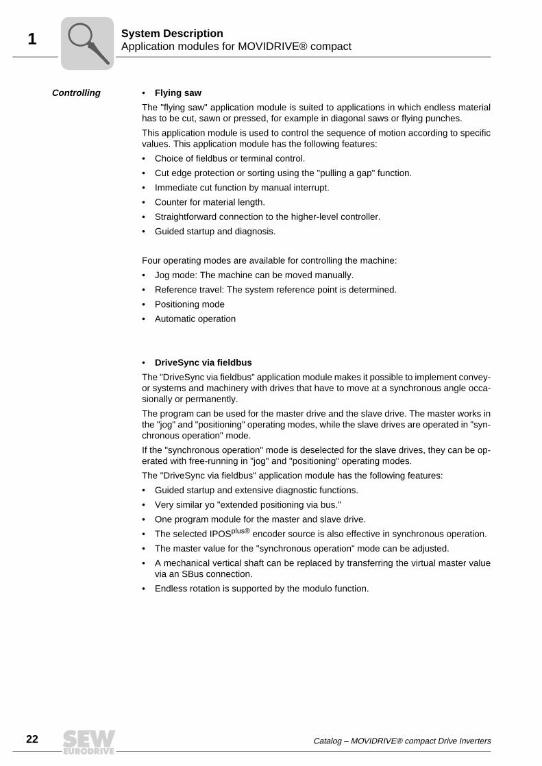
22
1 pplication modules for MOVIDRIVE® compactystem Description
Controlling • Flying saw
The "flying saw" application module is suited to applications in which endless materialhas to be cut, sawn or pressed, for example in diagonal saws or flying punches.
This application module is used to control the sequence of motion according to specificvalues. This application module has the following features:
• Choice of fieldbus or terminal control.
• Cut edge protection or sorting using the "pulling a gap" function.
• Immediate cut function by manual interrupt.
• Counter for material length.
• Straightforward connection to the higher-level controller.
• Guided startup and diagnosis.
Four operating modes are available for controlling the machine:
• Jog mode: The machine can be moved manually.
• Reference travel: The system reference point is determined.
• Positioning mode
• Automatic operation
• DriveSync via fieldbus
The "DriveSync via fieldbus" application module makes it possible to implement convey-or systems and machinery with drives that have to move at a synchronous angle occa-sionally or permanently.
The program can be used for the master drive and the slave drive. The master works inthe "jog" and "positioning" operating modes, while the slave drives are operated in "syn-chronous operation" mode.
If the "synchronous operation" mode is deselected for the slave drives, they can be op-erated with free-running in "jog" and "positioning" operating modes.
The "DriveSync via fieldbus" application module has the following features:
• Guided startup and extensive diagnostic functions.
• Very similar yo "extended positioning via bus."
• One program module for the master and slave drive.
• The selected IPOSplus® encoder source is also effective in synchronous operation.
• The master value for the "synchronous operation" mode can be adjusted.
• A mechanical vertical shaft can be replaced by transferring the virtual master valuevia an SBus connection.
• Endless rotation is supported by the modulo function.
AS
Catalog – MOVIDRIVE® compact Drive Inverters

1Application modules for MOVIDRIVE® compactSystem Description
Four operating modes are available for controlling the application:
• Jog mode
• Reference travel
• Positioning mode
• Synchronous operation
– The electrical connection of the master/slave can be made using the X14 encoderconnection or an SBus connection.
– If the SBus connection is used, the content of the send object can be adjusted.– Time or position-related sequence of motion for synchronization processes.– The startup cycle process can also be started with interrupt control.
• Sensor-based positioning
This application module is used to position the drive using an external sensor signal plusan adjustable remaining distance. This application module is especially suitable for ap-plications in the following industrial sectors:
• Materials handling
– Trolleys– Hoists– Rail vehicles
• Logistics
– Storage and retrieval units– Transverse carriages
Catalog – MOVIDRIVE® compact Drive Inverters
23
24
1 OVITOOLS® operating softwareystem Description
1.5 MOVITOOLS® operating software
Description MOVITOOLS® is a program package comprising SHELL, SCOPE and the IPOSplus®
compiler. You can use MOVITOOLS® to address the MOVIDRIVE® MDX60B/61B andMOVIDRIVE® compact unit series.
• SHELL can be used to start up the drive and set its parameters quickly and easily.
• SCOPE provides extensive oscilloscope functions for drive diagnostics.
• IPOSplus® compiler provides a user-friendly way of writing programs for applicationsin a high-level language.
• The assembler enables you to write programs directly on the machine.
• The device status shows you the status of the connected unit.
Various application modules, such as table positioning, are already stored inMOVITOOLS® as IPOSplus® programs and can be activated using the applicationversion units.
MOVITOOLS® is supplied on a CD-ROM and can also be downloaded from the SEWhomepage (http://www.sew-eurodrive.de). MOVITOOLS® can be operated with thefollowing operating systems:
• Windows® 95
• Windows® 98
• Windows NT® 4.0
• Windows® 2000
• Windows® Me
• Windows® XP
02719AENFigure 7: MOVITOOLS® window
MS
Catalog – MOVIDRIVE® compact Drive Inverters
2CE marking, UL approval and unit designationTechnical Data and Dimension Drawings
2 Technical Data and Dimension Drawings2.1 CE marking, UL approval and unit designation
CE marking • Low voltage directive
MOVIDRIVE® compact drive inverters comply with the regulations of the LowVoltage Directive 73/23/EEC.
• Electromagnetic compatibility (EMC)
MOVIDRIVE® compact drive inverters are designed for use as components forinstallation in machines and systems. They comply with the EMC product standardEN 61800-3 "Variable-speed electrical drives." Provided the installation instructionsare complied with, they satisfy the appropriate requirements for CE marking of theentire machine/system in which they are installed, on the basis of the EMC Directive89/336/EEC.
MOVIDRIVE® compact drive inverters size 1 and 2 are equipped with a line filter asstandard. These units comply with class A limit to EN 55011 and EN 55014 on theline side without further measures.
The CE mark on the nameplate indicates conformity with the Low Voltage Directive73/23/EEC and the EMC Directive 89/336/EEC. We can provide a copy of the declara-tion of conformity on request.
UL / cUL / GOST-R
UL, cUL approval (USA) and the GOST-R certificate (Russia) have been approved forthe MOVIDRIVE® compact unit series. cUL is equivalent to CSA approval.
C-Tick C-Tick approval has been granted for the entire MOVIDRIVE® compact unit series. C-Tick certifies conformity with ACA (Australian Communications Authority) standards.
UL®C UL®
Catalog – MOVIDRIVE® compact Drive Inverters
Pi
fkVA
Hz
n
25
26
2 E marking, UL approval and unit designationechnical Data and Dimension Drawings
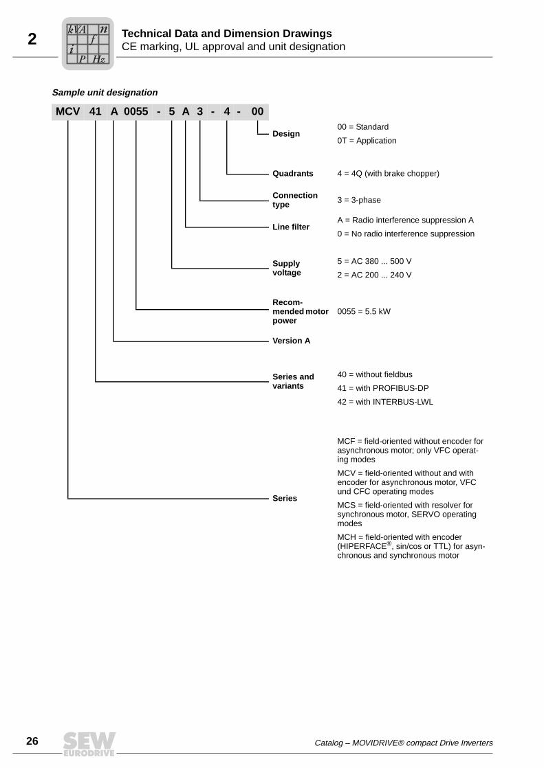
Sample unit designation
MCV 41 A 0055 - 5 A 3 - 4 - 00
Design00 = Standard
0T = Application
Quadrants 4 = 4Q (with brake chopper)
Connection type 3 = 3-phase
Line filterA = Radio interference suppression A
0 = No radio interference suppression
Supply voltage
5 = AC 380 ... 500 V
2 = AC 200 ... 240 V
Recom-mended motor power
0055 = 5.5 kW
Version A
Series and variants
40 = without fieldbus
41 = with PROFIBUS-DP
42 = with INTERBUS-LWL
Series
MCF = field-oriented without encoder for asynchronous motor; only VFC operat-ing modes
MCV = field-oriented without and with encoder for asynchronous motor, VFC und CFC operating modes
MCS = field-oriented with resolver for synchronous motor, SERVO operating modes
MCH = field-oriented with encoder (HIPERFACE®, sin/cos or TTL) for asyn-chronous and synchronous motor
CT
Pi
fkVA
Hz
n
Catalog – MOVIDRIVE® compact Drive Inverters

2General technical dataTechnical Data and Dimension Drawings
2.2 General technical data
The following table lists the technical data applicable to all MOVIDRIVE® compact driveinverters, regardless of their type, version, size and power rating.
MOVIDRIVE® compact All sizes
Interference immunity Complies with EN 61800-3
Interference emission with EMC-compliant installation
Sizes 1 to 5:• Comply with EN 61800-3• According to class B limit to EN 55011 and EN 55014
Sizes 1 and 2:• Comply with class A limit to EN 55011 and EN 55014 on
the line side without further measures
Ambient temperature ϑU
Derating ambient temperature
Climate class
0 °C...+50 °C when ID = 100 % IN and fPWM = 4 kHz0 °C...+40 °C when ID = 125 % IN and fPWM = 4 kHz0 °C...+40 °C when ID = 100 % IN and fPWM = 8 kHzDerating:• 2.5 % IN per K between 40 °C - 50 °C• 3.5 % IN per K between 50 °C - 60 °C
EN 60721-3-3, class 3K3
Storage temperature1) ϑL
1) In case of long-term storage, the unit must be connected to the mains voltage for at least 5 minutes everytwo years, otherwise the unit’s service life may be reduced.
–25 °C...+70 °C (EN 60721-3-3, class 3K3)DBG keypad: –20 °C...+60 °C
Cooling type (DIN 51751) Forced coolingTemperature-controlled fan, response threshold at ϑ = 45°C
Enclosure Sizes 1 to 3EN 60529 Sizes 4 and 5(NEMA 1)
IP20IP00 (power connections); IP10 with mounted plexiglas cover supplied as standard
Operating mode Continuous operation with 50 % overload capacity
Overvoltage category III according to IEC 60664-1 (VDE 0110-1)
Pollution class 2 according to IEC 60664-1 (VDE 0110-1)
Installation altitude Up to h ≤ 1,000 m there are no restrictions.At h ≥ 1,000 m and above the following restrictions apply:• From 1,000 m to max. 4,000 m:
– IN reduction by 1% per 100 m (330 ft)
• From 2,000 m to max. 4,000 m:– AC 230 V units: VN reduction by AC 3 V per 100 m– AC 500 V units: VN reduction by AC 6 V per 100 m
Over 2,000 m only overvoltage class 2; external measures required for overvoltage class 3. Overvoltage classes accord-ing to DIN VDE 0110-1.
Catalog – MOVIDRIVE® compact Drive Inverters
Pi
fkVA
Hz
n
27

28
2 OVIDRIVE® compact MC_4_A...-5_3 (AC 400/500 V units)echnical Data and Dimension Drawings
2.3 MOVIDRIVE® compact MC_4_A...-5_3 (AC 400/500 V units)
Size 1
02570AXX
MOVIDRIVE® compact 0015-5A3-4-0_ 0022-5A3-4-0_ 0030-5A3-4-0_ 0040-5A3-4-0_
INPUT
Supply voltage Vmains 3 × AC 380 V –10 % ... 3 × AC 500 V +10 %
Supply frequency fmains 50 Hz ... 60 Hz ±5 %
Rated mains current1) Imains 100 %(when Vmains = 3 × AC 400 V) 125%
AC 3.6 AAC 4.5 A
AC 5.0 AAC 6.2 A
AC 6.3 AAC 7.9 A
AC 8.6 AAC 10.7 A
OUTPUT
Apparent output power2) SN(when Vmains = 3 × AC 400...500 V)
2.8 kVA 3.8 kVA 4.9 kVA 6.6 kVA
Rated output current1) IN(when Vmains = 3 × AC 400 V)
AC 4 A AC 5.5 A AC 7 A AC 9.5 A
Current limitation Imax Motor and regenerative 150 % IN, duration depending on the capacity utilization
Internal current limitation Imax = 0...150 % can be set in menu (P303 / P313)
Minimum permitted braking RBRminresistance value (4Q operation)
68 Ω
Output voltage VA Max. Vmains
PWM frequency fPWM Following values can be set: 4/8/12/16 kHz
Speed range / resolution nA / ∆nA –5500 ... 0 ... +5500 min–1 / 0.2 min–1 across the entire range
GENERAL INFORMATION
Power loss at PN PVmax 85 W 105 W 130 W 180 W
Cooling air consumption 40 m3/h
Weight 2.8 kg
Dimensions W × H × D MCF/MCV/MCS: 105 × 315 × 155 mmMCH: 105 × 315 × 161 mm
1) When Vmains = 3 × AC 500 V, the mains currents and output currents must be reduced by 20 % compared to the rated data.
2) The power data applies to fPWM = 4 kHz (factory setting for VFC operating modes).
MT
Pi
fkVA
Hz
n
Catalog – MOVIDRIVE® compact Drive Inverters

2MOVIDRIVE® compact MC_4_A...-5_3 (AC 400/500 V units)Technical Data and Dimension Drawings
MCF4_A standard version (VFC) 0015-5A3-4-00 0022-5A3-4-00 0030-5A3-4-00 0040-5A3-4-00
Part number MCF40A (without fieldbus) 826 738 3 826 739 1 826 740 5 826 741 3
Part number MCF41A (with PROFIBUS-DP) 826 835 5 826 836 3 826 837 1 826 838 X
MCF4_A application version (VFC) 0015-5A3-4-0T 0022-5A3-4-0T 0030-5A3-4-0T 0040-5A3-4-0T
Part number MCF40A (without fieldbus) 827 426 6 827 427 4 827 428 2 827 429 0
Part number MCF41A (with PROFIBUS-DP) 827 449 5 827 450 9 827 451 7 827 452 5
Constant loadRecommended motor power
PMot
1.5 kW 2.2 kW 3.0 kW 4.0 kW
Variable torque load or constantload without overloadRecommended motor power
PMot
2.2 kW 3.0 kW 4.0 kW 5.5 kW
Continuous output current = 125% IN ID(when Vmains = 3 × AC 400 V and fPWM = 4 kHz)
AC 5 A AC 6.9 A AC 8.8 A AC 11.9 A
MCV4_A standard version (VFC/CFC) 0015-5A3-4-00 0022-5A3-4-00 0030-5A3-4-00 0040-5A3-4-00
Part number MCV40A (without fieldbus) 826 908 4 826 909 2 826 910 6 826 911 4
Part number MCV41A (with PROFIBUS-DP) 826 928 9 826 929 7 826 930 0 826 931 9
MCV4_A application version (VFC/CFC) 0015-5A3-4-0T 0022-5A3-4-0T 0030-5A3-4-0T 0040-5A3-4-0T
Part number MCV40A (without fieldbus) 827 472 X 827 473 8 827 474 6 827 475 4
Part number MCV41A (with PROFIBUS-DP) 827 495 9 827 496 7 827 497 5 827 498 3
VFC operating mode Recommended motor power → MCF4_A
CFC operating mode (fPWM = 8 kHz)Continuous output current = 100% IN ID AC 4 A AC 5.5 A AC 7 A AC 9.5 A
Recommended motor power → section CFC motor selection
MCS4_A standard version (SERVO) 0015-5A3-4-00 0022-5A3-4-00 0030-5A3-4-00 0040-5A3-4-00
Part number MCS40A (without fieldbus) 827 060 0 827 061 9 827 062 7 827 063 5
Part number MCS41A (with PROFIBUS-DP) 827 077 5 827 078 3 827 079 1 827 080 5
MCS4_A application version (SERVO) 0015-5A3-4-0T 0022-5A3-4-0T 0030-5A3-4-0T 0040-5A3-4-0T
Part number MCS40A (without fieldbus) 827 518 1 827 519 X 827 520 3 827 521 1
Part number MCS41A (with PROFIBUS-DP) 827 541 6 827 542 4 827 543 2 827 544 0
SERVO operating mode (fPWM = 8 kHz)Continuous output current = 100% IN ID AC 4 A AC 5.5 A AC 7 A AC 9.5 A
Recommended motor power → section SERVO motor selection
MCH4_A standard version(VFC/CFC/SERVO) 0015-5A3-4-00 0022-5A3-4-00 0030-5A3-4-00 0040-5A3-4-00
Part number MCH40A (without fieldbus) 827 603 X 827 604 8 827 605 6 827 606 4
Part number MCH41A (with PROFIBUS-DP) 827 649 8 827 650 1 827 651 X 827 652 8
Part number MCH42A (with INTERBUS-LWL) 827 565 3 827 566 1 827 567 X 827 568 8
MCH4_A application version(VFC/CFC/SERVO) 0015-5A3-4-0T 0022-5A3-4-0T 0030-5A3-4-0T 0040-5A3-4-0T
Part number MCH40A (without fieldbus) 827 626 9 827 627 7 827 628 5 827 629 3
Part number MCH41A (with PROFIBUS-DP) 827 672 2 827 673 0 827 674 9 827 675 7
Part number MCH42A (with INTERBUS-LWL) 827 158 5 827 159 3 827 160 7 827 161 5
VFC operating mode Recommended motor power → MCF4_A
CFC/SERVO operating mode (fPWM = 8 kHz)Continuous output current = 100% IN ID AC 4 A AC 5.5 A AC 7 A AC 9.5 A
Recommended motor power → section CFC/SERVO motor selection
Catalog – MOVIDRIVE® compact Drive Inverters
Pi
fkVA
Hz
n
29

30
2 OVIDRIVE® compact MC_4_A...-5_3 (AC 400/500 V units)echnical Data and Dimension Drawings
Size 2
02571AXX
MOVIDRIVE® compact 0055-5A3-4-0_ 0075-5A3-4-0_ 0110-5A3-4-0_
INPUT
Supply voltage Vmains 3 × AC 380 V –10 % ... 3 × AC 500 V +10 %
Supply frequency fmains 50 Hz ... 60 Hz ±5 %
Rated mains current1) Imains 100 %(when Vmains = 3 × AC 400 V) 125%
AC 11.3 AAC 14.1 A
AC 14.4 AAC 18.0 A
AC 21.6 AAC 27.0 A
OUTPUT
Apparent output power2) SN(when Vmains = 3 × AC 400...500 V)
8.7 kVA 11.2 kVA 16.8 kVA
Rated output current1) IN(when Vmains = 3 × AC 400 V)
AC 12.5 A AC 16 A AC 24 A
Current limitation Imax Motor and regenerative 150 % IN, duration depending on the capacity utilization
Internal current limitation Imax = 0...150 % can be set in menu (P303 / P313)
Minimum permitted braking RBRminresistance value (4Q operation)
47 Ω 22 Ω
Output voltage VA Max. Vmains
PWM frequency fPWM Following values can be set: 4/8/12/16 kHz
Speed range / resolution nA / ∆nA –5500 ... 0 ... +5500 min–1 / 0.2 min–1 across the entire range
GENERAL INFORMATION
Power loss at PN PVmax 220 W 290 W 400 W
Cooling air consumption 80 m3/h
Weight 5.9 kg
Dimensions W × H × D MCF/MCV/MCS: 130 × 335 × 207 mmMCH: 130 × 335 × 213 mm
1) When Vmains = 3 × AC 500 V, the mains currents and output currents must be reduced by 20 % compared to the rated data.
2) The power data applies to fPWM = 4 kHz (factory setting for VFC operating modes).
MT
Pi
fkVA
Hz
n
Catalog – MOVIDRIVE® compact Drive Inverters

2MOVIDRIVE® compact MC_4_A...-5_3 (AC 400/500 V units)Technical Data and Dimension Drawings
MCF4_A standard version (VFC) 0055-5A3-4-00 0075-5A3-4-00 0110-5A3-4-00
Part number MCF40A (without fieldbus) 826 742 1 826 743 X 826 744 8
Part number MCF41A (with PROFIBUS-DP) 826 839 8 826 840 1 826 841 X
MCF4_A application version (VFC) 0055-5A3-4-0T 0075-5A3-4-0T 0110-5A3-4-0T
Part number MCF40A (without fieldbus) 827 430 4 827 431 2 827 432 0
Part number MCF41A (with PROFIBUS-DP) 827 453 3 827 454 1 827 455 X
Constant loadRecommended motor power
PMot
5.5 kW 7.5 kW 11 kW
Variable torque load or constantload without overloadRecommended motor power
PMot
7.5 kW 11 kW 15 kW
Continuous output current = 125% IN ID(when Vmains = 3 × AC 400 V and fPWM = 4 kHz)
AC 15.6 A AC 20.0 A AC 30.0 A
MCV4_A standard version (VFC/CFC) 0055-5A3-4-00 0075-5A3-4-00 0110-5A3-4-00
Part number MCV40A (without fieldbus) 826 912 2 826 913 0 826 914 9
Part number MCV41A (with PROFIBUS-DP) 826 932 7 826 933 5 826 934 3
MCV4_A application version (VFC/CFC) 0055-5A3-4-0T 0075-5A3-4-0T 0110-5A3-4-0T
Part number MCV40A (without fieldbus) 827 476 2 827 477 0 827 478 9
Part number MCV41A (with PROFIBUS-DP) 827 499 1 827 500 9 827 501 7
VFC operating mode Recommended motor power → MCF4_A
CFC operating mode (fPWM = 8 kHz)Continuous output current = 100% IN ID AC 12.5 A AC 16 A AC 24 A
Recommended motor power → section CFC motor selection
MCS4_A standard version (SERVO) 0055-5A3-4-00 0075-5A3-4-00 0110-5A3-4-00
Part number MCS40A (without fieldbus) 827 064 3 827 065 1 827 066 X
Part number MCS41A (with PROFIBUS-DP) 827 081 3 827 082 1 827 083 X
MCS4_A application version (SERVO) 0055-5A3-4-0T 0075-5A3-4-0T 0110-5A3-4-0T
Part number MCS40A (without fieldbus) 827 522 X 827 523 8 827 524 6
Part number MCS41A (with PROFIBUS-DP) 827 545 9 827 546 7 827 547 5
SERVO operating mode (fPWM = 8 kHz)Continuous output current = 100% IN ID AC 12.5 A AC 16 A AC 24 A
Recommended motor power → section SERVO motor selection
MCH4_A standard version(VFC/CFC/SERVO) 0055-5A3-4-00 0075-5A3-4-00 0110-5A3-4-00
Part number MCH40A (without fieldbus) 827 607 2 827 608 0 827 609 9
Part number MCH41A (with PROFIBUS-DP) 827 653 6 827 654 4 827 655 2
Part number MCH42A (with INTERBUS-LWL) 827 569 6 827 570 X 827 571 8
MCH4_A application version(VFC/CFC/SERVO) 0055-5A3-4-0T 0075-5A3-4-0T 0110-5A3-4-0T
Part number (withot fieldbus) 827 630 7 827 631 5 827 632 3
Part number (with PROFIBUS-DP) 827 676 5 827 677 3 827 678 1
Part number (with INTERBUS-LWL) 827 162 3 827 163 1 827 164 X
VFC operating mode Recommended motor power → MCF4_A
CFC/SERVO operating mode (fPWM = 8 kHz)Continuous output current = 100% IN ID AC 12.5 A AC 16 A AC 24 A
Recommended motor power → section CFC/SERVO motor selection
Catalog – MOVIDRIVE® compact Drive Inverters
Pi
fkVA
Hz
n
31

32
2 OVIDRIVE® compact MC_4_A...-5_3 (AC 400/500 V units)echnical Data and Dimension Drawings
Size 3
02572AXX
MOVIDRIVE® compact 0150-503-4-0_ 0220-503-4-0_ 0300-503-4-0_
INPUT
Supply voltage Vmains 3 × AC 380 V –10 % ... 3 × AC 500 V +10 %
Supply frequency fmains 50 Hz ... 60 Hz ±5 %
Rated mains current1) Imains 100 %(when Vmains = 3 × AC 400 V) 125%
AC 28.8 AAC 36 A
AC 41.4 AAC 51.7 A
AC 54 AAC 67.5 A
OUTPUT
Apparent output power2) SN(when Vmains = 3 × AC 400...500 V)
22.2 kVA 31.9 kVA 41.6 kVA
Rated output current1) IN(when Vmains = 3 × AC 400 V)
AC 32 A AC 46 A AC 60 A
Current limitation Imax Motor and regenerative 150 % IN, duration depending on the capacity utilization
Internal current limitation Imax = 0...150 % can be set in menu (P303 / P313)
Minimum permitted braking RBRminresistance value (4Q operation)
15 Ω 12 Ω
Output voltage VA Max. Vmains
PWM frequency fPWM Following values can be set: 4/8/12/16 kHz
Speed range / resolution nA / ∆nA –5500 ... 0 ... +5500 min–1 / 0.2 min–1 across the entire range
GENERAL INFORMATION
Power loss at PN PVmax 550 W 750 W 950 W
Cooling air consumption 180 m3/h
Weight 14.3 kg
Dimensions W × H × D MCF/MCV/MCS: 200 × 465 × 227 mmMCH: 200 × 465 × 233 mm
1) When Vmains = 3 × AC 500 V, the mains currents and output currents must be reduced by 20 % compared to the rated data.
2) The power data applies to fPWM = 4 kHz (factory setting for VFC operating modes).
MT
Pi
fkVA
Hz
n
Catalog – MOVIDRIVE® compact Drive Inverters

2MOVIDRIVE® compact MC_4_A...-5_3 (AC 400/500 V units)Technical Data and Dimension Drawings
MCF4_A standard version (VFC) 0150-503-4-00 0220-503-4-00 0300-503-4-00
Part number MCF40A (without fieldbus) 826 745 6 826 746 4 826 747 2
Part number MCF41A (with PROFIBUS-DP) 826 842 8 826 843 6 826 844 4
MCF4_A application version (VFC) 0150-503-4-0T 0220-503-4-0T 0300-503-4-0T
Part number MCF40A (without fieldbus) 827 433 9 827 434 7 827 435 5
Part number MCF41A (with PROFIBUS-DP) 827 456 8 827 457 6 827 458 4
Constant loadRecommended motor power
PMot
15 kW 22 kW 30 kW
Variable torque load or constantload without overloadRecommended motor power
PMot
22 kW 30 kW 37 kW
Continuous output current = 125% IN ID(when Vmains = 3 × AC 400 V and fPWM = 4 kHz)
AC 40.0 A AC 57.5 A AC 75.0 A
MCV4_A standard version (VFC/CFC) 0150-503-4-00 0220-503-4-00 0300-503-4-00
Part number MCV40A (without fieldbus) 826 915 7 826 916 5 826 917 3
Part number MCV41A (with PROFIBUS-DP) 826 935 1 826 936 X 826 937 8
MCV4_A application version (VFC/CFC) 0150-503-4-0T 0220-503-4-0T 0300-503-4-0T
Part number MCV40A (without fieldbus) 827 479 7 827 480 0 827 481 9
Part number MCV41A (with PROFIBUS-DP) 827 502 5 827 503 3 827 504 1
VFC operating mode Recommended motor power → MCF4_A
CFC operating mode (fPWM = 8 kHz)Continuous output current = 100% IN ID AC 32 A AC 46 A AC 60 A
Recommended motor power → section CFC motor selection
MCS4_A standard version (SERVO) 0150-503-4-00 0220-503-4-00 0300-503-4-00
Part number MCS40A (without fieldbus) 827 067 8 827 068 6 827 069 4
Part number MCS41A (with PROFIBUS-DP) 827 084 8 827 085 6 827 086 4
MCS4_A application version (SERVO) 0150-503-4-0T 0220-503-4-0T 0300-503-4-0T
Part number MCS40A (without fieldbus) 827 525 4 827 526 2 827 527 0
Part number MCS41A (with PROFIBUS-DP) 827 548 3 827 549 1 827 550 5
SERVO operating mode (fPWM = 8 kHz)Continuous output current = 100% IN ID AC 32 A AC 46 A AC 60 A
Recommended motor power → section SERVO motor selection
MCH4_A standard version(VFC/CFC/SERVO) 0150-503-4-00 0220-503-4-00 0300-503-4-00
Part number MCH40A (without fieldbus) 827 610 2 827 611 0 827 612 9
Part number MCH41A (with PROFIBUS-DP) 827 656 0 827 657 9 827 658 7
Part number MCH42A (with INTERBUS-LWL) 827 572 6 827 573 4 827 574 2
MCH4_A application version(VFC/CFC/SERVO) 0150-503-4-0T 0220-503-4-0T 0300-503-4-0T
Part number MCH40A (without fieldbus) 827 633 1 827 634 X 827 635 8
Part number MCH41A (with PROFIBUS-DP) 827 679 X 827 680 3 827 681 1
Part number MCH42A (with INTERBUS-LWL) 827 165 8 827 166 6 827 167 4
VFC operating mode Recommended motor power → MCF4_A
CFC/SERVO operating mode (fPWM = 8 kHz)Continuous output current = 100% IN ID AC 32 A AC 46 A AC 60 A
Recommended motor power → section CFC/SERVO motor selection
Catalog – MOVIDRIVE® compact Drive Inverters
Pi
fkVA
Hz
n
33

34
2 OVIDRIVE® compact MC_4_A...-5_3 (AC 400/500 V units)echnical Data and Dimension Drawings
Size 4
02573AXX
MOVIDRIVE® compact 0370-503-4-0_ 0450-503-4-0_
INPUT
Supply voltage Vmains 3 × AC 380 V –10 % ... 3 × AC 500 V +10 %
Supply frequency fmains 50 Hz ... 60 Hz ±5 %
Rated mains current1) Imains 100 %(when Vmains = 3 × AC 400 V) 125%
AC 65.7 AAC 81.9 A
AC 80.1 AAC 100.1 A
OUTPUT
Apparent output power2) SN(when Vmains = 3 × AC 400...500 V)
51.1 kVA 62.3 kVA
Rated output current1) IN(when Vmains = 3 × AC 400 V)
AC 73 A AC 89 A
Current limitation Imax Motor and regenerative 150 % IN, duration depending on the capacity utilization
Internal current limitation Imax = 0...150 % can be set in menu (P303 / P313)
Minimum permitted braking RBRminresistance value (4Q operation)
6 Ω
Output voltage VA Max. Vmains
PWM frequency fPWM Following values can be set: 4/8/12/16 kHz
Speed range / resolution nA / ∆nA –5500 ... 0 ... +5500 min–1 / 0.2 min–1 across the entire range
GENERAL INFORMATION
Power loss at PN PVmax 1200 W 1450 W
Cooling air consumption 180 m3/h
Weight 26.3 kg
Dimensions W × H × D MCF/MCV/MCS: 280 × 522 × 227 mmMCH: 280 × 522 × 233 mm
1) When Vmains = 3 × AC 500 V, the mains currents and output currents must be reduced by 20 % compared to the rated data.
2) The power data applies to fPWM = 4 kHz (factory setting for VFC operating modes).
MT
Pi
fkVA
Hz
n
Catalog – MOVIDRIVE® compact Drive Inverters

2MOVIDRIVE® compact MC_4_A...-5_3 (AC 400/500 V units)Technical Data and Dimension Drawings
MCF4_A standard version (VFC) 0370-503-4-00 0450-503-4-00
Part number MCF40A (without fieldbus) 826 748 0 826 749 9
Part number MCF41A (with PROFIBUS-DP) 826 845 2 826 846 0
MCF4_A application version (VFC) 0370-503-4-0T 0450-503-4-0T
Part number MCF40A (without fieldbus) 827 436 3 827 437 1
Part number MCF41A (with PROFIBUS-DP) 827 459 2 827 460 6
Constant loadRecommended motor power
PMot
37 kW 45 kW
Variable torque load or constantload without overloadRecommended motor power
PMot
45 kW 55 kW
Continuous output current = 125% IN ID(when Vmains = 3 × AC 400 V and fPWM = 4 kHz)
AC 91 A AC 111 A
MCV4_A standard version (VFC/CFC) 0370-503-4-00 0450-503-4-00
Part number MCV40A (without fieldbus) 826 918 1 826 919 X
Part number MCV41A (with PROFIBUS-DP) 826 938 6 826 939 4
MCV4_A application version (VFC/CFC) 0370-503-4-0T 0450-503-4-0T
Part number MCV40A (without fieldbus) 827 482 7 827 483 5
Part number MCV41A (with PROFIBUS-DP) 827 505 X 827 506 8
VFC operating mode Recommended motor power → MCF4_A
CFC operating mode (fPWM = 8 kHz)Continuous output current = 100% IN ID AC 73 A AC 89 A
Recommended motor power → section CFC motor selection
MCS4_A standard version (SERVO) 0370-503-4-00 0450-503-4-00
Part number MCS40A (without fieldbus) 827 070 8
Part number MCS41A (with PROFIBUS-DP) 827 087 2
MCS4_A application version (SERVO) 0370-503-4-0T 0450-503-4-0T
Part number MCS40A (without fieldbus) 827 528 9 827 529 7
Part number MCS41A (with PROFIBUS-DP) 827 551 3 827 552 1
SERVO operating mode (fPWM = 8 kHz)Continuous output current = 100% IN ID AC 73 A AC 89 A
Recommended motor power → section SERVO motor selection
MCH4_A standard version(VFC/CFC/SERVO) 0370-503-4-00 0450-503-4-00
Part number MCH40A (without fieldbus) 827 613 7 827 614 5
Part number MCH41A (with PROFIBUS-DP) 827 659 5 827 660 9
Part number MCH42A (with INTERBUS-LWL) 827 575 0 827 576 9
MCH4_A application version(VFC/CFC/SERVO) 0370-503-4-0T 0450-503-4-0T
Part number MCH40A (without fieldbus) 827 636 6 827 637 4
Part number MCH41A (with PROFIBUS-DP) 827 682 X 827 683 8
Part number MCH42A (with INTERBUS-LWL) 827 168 2 827 169 0
VFC operating mode Recommended motor power → MCF4_A
CFC/SERVO operating mode (fPWM = 8 kHz)Continuous output current = 100% IN ID AC 73 A AC 89 A
Recommended motor power → section CFC/SERVO motor selection
Catalog – MOVIDRIVE® compact Drive Inverters
Pi
fkVA
Hz
n
35

36
2 OVIDRIVE® compact MC_4_A...-5_3 (AC 400/500 V units)echnical Data and Dimension Drawings
Size 5
02574AXX
MOVIDRIVE® compact 0550-503-4-0_ 0750-503-4-0_
INPUT
Supply voltage Vmains 3 × AC 380 V –10 % ... 3 × AC 500 V +10 %
Supply frequency fmains 50 Hz ... 60 Hz ±5 %
Rated mains current1) Imains 100 %(when Vmains = 3 × AC 400 V) 125%
AC 94.5 AAC 118.1 A
AC 117.0 AAC 146.3 A
OUTPUT
Apparent output power2) SN(when Vmains = 3 × AC 400...500 V)
73.5 kVA 91.0 kVA
Rated output current1) IN(when Vmains = 3 × AC 400 V)
AC 105 A AC 130 A
Current limitation Imax Motor and regenerative 150% IN, duration depending on capacity utilization
Internal current limitation Imax = 0...150 % can be set in menu (P303 / P313)
Minimum permitted braking RBRminresistance value (4Q operation)
6 Ω 4 Ω
Output voltage VA Max. Vmains
PWM frequency fPWM Following values can be set: 4/8/12/16 kHz
Speed range / resolution nA / ∆nA –5500 ... 0 ... +5500 min–1 / 0.2 min–1 across the entire range
GENERAL INFORMATION
Power loss at PN PVmax 1700 W 2000 W
Cooling air consumption 360 m3/h
Weight 34.3 kg
Dimensions W × H × D 280 × 610 × 330 mm
1) When Vmains = 3 × AC 500 V, the mains currents and output currents must be reduced by 20 % compared to the rated data.
2) The power data applies to fPWM = 4 kHz (factory setting for VFC operating modes).
MT
Pi
fkVA
Hz
n
Catalog – MOVIDRIVE® compact Drive Inverters

2MOVIDRIVE® compact MC_4_A...-5_3 (AC 400/500 V units)Technical Data and Dimension Drawings
MCF4_A standard version (VFC) 0550-503-4-00 0750-503-4-00
Part number MCF40A (without fieldbus) 826 750 2 826 751 0
Part number MCF41A (with PROFIBUS-DP) 826 847 9 826 848 7
MCF4_A application version (VFC) 0550-503-4-0T 0750-503-4-0T
Part number MCF40A (without fieldbus) 827 438 X 827 439 8
Part number MCF41A (with PROFIBUS-DP) 827 461 4 827 462 2
Constant loadRecommended motor power
PMot
55 kW 75 kW
Variable torque load or constantload without overloadRecommended motor power
PMot
75 kW 90 kW
Continuous output current = 125% IN ID(when Vains = 3 × AC 400 V and fPWM = 4 kHz)
AC 131 A AC 162 A
MCV4_A standard version (VFC/CFC) 0550-503-4-00 0750-503-4-00
Part number MCV40A (without fieldbus) 826 920 3 826 921 1
Part number MCV41A (with PROFIBUS-DP) 826 940 8 826 941 6
MCV4_A application version (VFC/CFC) 0550-503-4-0T 0750-503-4-0T
Part number MCV40A (without fieldbus) 827 484 3 827 485 1
Part number MCV41A (with PROFIBUS-DP) 827 507 6 827 508 4
VFC operating mode Recommended motor power → MCF4_A
CFC operating mode (fPWM = 8 kHz)Continuous output current = 100% IN ID AC 105 A AC 130 A
Recommended motor power → section CFC motor selection
MCS4_A standard version (SERVO) 0550-503-4-00 0750-503-4-00
Part number MCS40A (without fieldbus)
Part number MCS41A (with PROFIBUS-DP)
MCS4_A application version (SERVO) 0550-503-4-0T 0750-503-4-0T
Part number MCS40A (without fieldbus) 827 530 0 827 531 9
Part number MCS41A (with PROFIBUS-DP) 827 553 X 827 554 8
SERVO operating mode (fPWM = 8 kHz)Continuous output current = 100% IN ID AC 105 A AC 130 A
Recommended motor power → section SERVO motor selection
MCH4_A standard version(VFC/CFC/SERVO) 0550-503-4-00 0750-503-4-00
Part number MCH40A (without fieldbus) 827 615 3 827 616 1
Part number MCH41A (with PROFIBUS-DP) 827 661 7 827 662 5
Part number MCH42A (with INTERBUS-LWL) 827 577 7 827 578 5
MCH4_A application version(VFC/CFC/SERVO) 0550-503-4-0T 0750-503-4-0T
Part number MCH40A (without fieldbus) 827 638 2 827 639 0
Part number MCH41A (with PROFIBUS-DP) 827 684 6 827 685 4
Part number MCH42A (with INTERBUS-LWL) 827 170 4 827 171 2
VFC operating mode Recommended motor power → MCF4_A
CFC/SERVO operating mode (fPWM = 8 kHz)Continuous output current = 100% IN ID AC 105 A AC 130 A
Recommended motor power → section CFC/SERVO motor selection
Catalog – MOVIDRIVE® compact Drive Inverters
Pi
fkVA
Hz
n
37

38
2 OVIDRIVE® compact MC_4_A...-2_3 (AC 230 V units)echnical Data and Dimension Drawings
2.4 MOVIDRIVE® compact MC_4_A...-2_3 (AC 230 V units)
Size 1
02570AXX
MOVIDRIVE® compact 0015-2A3-4-0_ 0022-2A3-4-0_ 0037-2A3-4-0_
INPUT
Supply voltage Vmains 3 × AC 200 V –10 % ... 3 × AC 240 V +10 %
Supply frequency fmains 50 Hz ... 60 Hz ±5 %
Rated mains current Imains 100 %(when Vmains = 3 × AC 230 V) 125%
AC 6.7 AAC 8.4 A
AC 7.8 AAC 9.8 A
AC 12.9 AAC 16.1 A
OUTPUT
Apparent output power1) SN(when Vmains = 3 × AC 230..240 V)
2.7 kVA 3.4 kVA 5.8 kVA
Rated output current IN(when Vmains = 3 × AC 230 V)
AC 7.3 A AC 8.6 A AC 14.5 A
Current limitation Imax Motor and regenerative 150 % IN, duration depending on the capacity utilization
Internal current limitation Imax = 0...150 % can be set in menu (P303 / P313)
Minimum permitted braking RBRminresistance value (4Q operation)
27 Ω
Output voltage VA Max. Vmains
PWM frequency fPWM Following values can be set: 4/8/12/16 kHz
Speed range / resolution nA / ∆nA –5500 ... 0 ... +5500 min–1 / 0.2 min–1 across the entire range
GENERAL INFORMATION
Power loss at PN PVmax 110 W 126 W 210 W
Cooling air consumption 40 m3/h
Weight 2.8 kg
Dimensions W × H × D MCF/MCV/MCS:105 × 315 × 155 mmMCH:105 × 315 × 161 mm
1) The power data applies to fPWM = 4 kHz (factory setting for VFC operating modes).
MT
Pi
fkVA
Hz
n
Catalog – MOVIDRIVE® compact Drive Inverters

2MOVIDRIVE® compact MC_4_A...-2_3 (AC 230 V units)Technical Data and Dimension Drawings
MCF4_A standard version (VFC) 0015-2A3-4-00 0022-2A3-4-00 0037-2A3-4-00
Part number MCF40A (without fieldbus) 826 752 9 826 753 7 826 754 5
Part number MCF41A (with PROFIBUS-DP) 826 853 3 826 854 1 826 855 X
MCF4_A application version (VFC) 0015-2A3-4-0T 0022-2A3-4-0T 0037-2A3-4-0T
Part number MCF40A (without fieldbus) 827 440 1 827 441 X 827 442 8
Part number MCF41A (with PROFIBUS-DP) 827 463 0 827 464 9 827 465 7
Constant loadRecommended motor power
PMot
1.5 kW 2.2 kW 3.7 kW
Variable torque load or constantload without overloadRecommended motor power
PMot
2.2 kW 3.7 kW 5.0 kW
Continuous output current = 125% IN ID(when Umains = 3 × AC 230 V and fPWM = 4 kHz)
AC 9.1 A AC 10.8 A AC 18.1 A
MCV4_A standard version (VFC/CFC) 0015-2A3-4-00 0022-2A3-4-00 0037-2A3-4-00
Part number MCV40A (without fieldbus) 826 922 X 826 923 8 826 924 6
Part number MCV41A (with PROFIBUS-DP) 826 942 4 826 943 2 826 944 0
MCV4_A application version (VFC/CFC) 0015-2A3-4-0T 0022-2A3-4-0T 0037-2A3-4-0T
Part number MCV40A (without fieldbus) 827 486 X 827 487 8 827 488 6
Part number MCV41A (with PROFIBUS-DP) 827 509 2 827 510 6 827 511 4
VFC operating mode Recommended motor power → MCF4_A
CFC operating mode (fPWM = 8 kHz)Continuous output current = 100% IN ID AC 7.3 A AC 8.6 A AC 14.5 A
Recommended motor power → section CFC motor selection
MCS4_A standard version (SERVO) 0015-2A3-4-00 0022-2A3-4-00 0037-2A3-4-00
Part number MCS40A (without fieldbus) 827 071 6 827 0724 827 073 2
Part number MCS41A (with PROFIBUS-DP) 827 088 0 827 089 9 827 090 2
MCS4_A application version (SERVO) 0015-2A3-4-0T 0022-2A3-4-0T 0037-2A3-4-0T
Part number MCS40A (without fieldbus) 827 532 7 827 533 5 827 534 3
Part number MCS41A (with PROFIBUS-DP) 827 555 6 827 556 4 827 557 2
SERVO operating mode Recommended motor power → MCS4_A
SERVO operating mode (fPWM = 8 kHz)Continuous output current = 100% IN ID AC 7.3 A AC 8.6 A AC 14.5 A
Recommended motor power → section SERVO motor selection
MCH4_A standard version(VFC/CFC) 0015-2A3-4-00 0022-2A3-4-00 0037-2A3-4-00
Part number MCH40A (without fieldbus) 827 617 X 827 618 8 827 619 6
Part number MCH41A (with PROFIBUS-DP) 827 663 3 827 664 1 827 665 X
Part number MCH42A (with INTERBUS-LWL) 827 588 2 827 589 0 827 590 4
MCH4_A application version(VFC/CFC) 0015-2A3-4-0T 0022-2A3-4-0T 0037-2A3-4-0T
Part number MCH40A (without fieldbus) 827 640 4 827 641 2 827 642 0
Part number MCH41A (with PROFIBUS-DP) 827 686 2 827 687 0 827 688 9
Part number MCH42A (with INTERBUS-LWL) 827 579 3 827 580 7 827 581 5
VFC operating mode Recommended motor power → MCF4_A
CFC/SERVO operating mode (fPWM = 8 kHz)Continuous output current = 100% IN ID AC 7.3 A AC 8.6 A AC 14.5 A
Recommended motor power → section CFC/SERVO motor selection
Catalog – MOVIDRIVE® compact Drive Inverters
Pi
fkVA
Hz
n
39

40
2 OVIDRIVE® compact MC_4_A...-2_3 (AC 230 V units)echnical Data and Dimension Drawings
Size 2
02571AXX
MOVIDRIVE® compact 0055-2A3-4-0_ 0075-2A3-4-0_
INPUT
Supply voltage Vmains 3 × AC 200 V –10 % ... 3 × AC 240 V +10 %
Supply frequency fmains 50 Hz ... 60 Hz ±5 %
Rated mains current Imains 100 %(when Vmains = 3 × AC 230 V) 125%
AC 19.5 AAC 24.4 A
AC 27.4 AAC 34.3 A
OUTPUT
Apparent output power1) SN(when Vmains = 3 × AC 230..240 V)
8.8 kVA 11.6 kVA
Rated output current IN(when Vmains = 3 × AC 230 V)
AC 22 A AC 29 A
Current limitation Imax Motor and regenerative 150 % IN, duration depending on the capacity utilization
Internal current limitation Imax = 0...150 % can be set in menu (P303 / P313)
Minimum permitted braking RBRminresistance value (4Q operation)
12 Ω
Output voltage VA Max. Vmains
PWM frequency fPWM Following values can be set: 4/8/12/16 kHz
Speed range / resolution nA / ∆nA –5500 ... 0 ... +5500 min–1 / 0.2 min–1 across the entire range
GENERAL INFORMATION
Power loss at PN PVmax 300 W 380 W
Cooling air consumption 80 m3/h
Weight 5.9 kg
Dimensions W × H × D MCF/MCV/MCS:130 × 335 × 207 mmMCH:130 × 335 × 213 mm
1) The power data applies to fPWM = 4 kHz (factory setting for VFC operating modes).
MT
Pi
fkVA
Hz
n
Catalog – MOVIDRIVE® compact Drive Inverters

2MOVIDRIVE® compact MC_4_A...-2_3 (AC 230 V units)Technical Data and Dimension Drawings
MCF4_A standard version (VFC) 0055-2A3-4-00 0075-2A3-4-00
Part number MCF40A (without fieldbus) 826 755 3 826 756 1
Part number MCF41A (with PROFIBUS-DP) 826 856 8 826 857 6
MCF4_A application version (VFC) 0055-2A3-4-0T 0075-2A3-4-0T
Part number MCF40A (without fieldbus) 827 443 6 827 444 4
Part number MCF41A (with PROFIBUS-DP) 827 466 5 827 467 3
Constant loadRecommended motor power
PMot
5.5 kW 7.5 kW
Variable torque load or constantload without overloadRecommended motor power
PMot
7.5 kW 11 kW
Continuous output current = 125% IN ID(when Vmains = 3 × AC 230 V and fPWM = 4 kHz)
AC 27.5 A AC 36.3 A
MCV4_A standard version (VFC/CFC) 0055-2A3-4-00 0075-2A3-4-00
Part number MCV40A (without fieldbus) 826 925 4 826 926 2
Part number MCV41A (with PROFIBUS-DP) 826 945 9 826 946 7
MCV4_A application version (VFC/CFC) 0055-2A3-4-0T 0075-2A3-4-0T
Part number MCV40A (without fieldbus) 827 489 4 827 490 8
Part number MCV41A (with PROFIBUS-DP) 827 512 2 827 513 0
VFC operating mode Recommended motor power → MCF4_A
CFC operating mode (fPWM = 8 kHz)Continuous output current = 100% IN ID AC 22 A AC 29 A
Recommended motor power → section CFC motor selection
MCS4_A standard version (SERVO) 0055-2A3-4-00 0075-2A3-4-00
Part number MCS40A (without fieldbus) 827 074 0 827 075 9
Part number MCS41A (with PROFIBUS-DP) 827 091 0 827 092 9
MCS4_A application version (SERVO) 0055-2A3-4-0T 0075-2A3-4-0T
Part number MCS40A (without fieldbus) 827 535 1 827 536 X
Part number MCS41A (with PROFIBUS-DP) 827 558 0 827 559 9
SERVO operating mode Recommended motor power → MCS4_A
SERVO operating mode (fPWM = 8 kHz)Continuous output current = 100% IN ID AC 22 A AC 29 A
Recommended motor power → section SERVO motor selection
MCH4_A standard version(VFC/CFC) 0055-2A3-4-00 0075-2A3-4-00
Part number MCH40A (without fieldbus) 827 620 X 827 621 8
Part number MCH41A (with PROFIBUS-DP) 827 666 8 827 667 6
Part number MCH42A (with INTERBUS-LWL) 827 591 2 827 592 0
MCH4_A application version(VFC/CFC) 0055-2A3-4-0T 0075-2A3-4-0T
Part number MCH40A (without fieldbus) 827 643 9 827 644 7
Part number MCH41A (with PROFIBUS-DP) 827 689 7 827 690 0
Part number MCH42A (with INTERBUS-LWL) 827 582 3 827 583 1
VFC operating mode Recommended motor power → MCF4_A
CFC/SERVO operating mode (fPWM = 8 kHz)Continuous output current = 100% IN ID AC 22 A AC 29 A
Recommended motor power → section CFC/SERVO motor selection
Catalog – MOVIDRIVE® compact Drive Inverters
Pi
fkVA
Hz
n
41

42
2 OVIDRIVE® compact MC_4_A...-2_3 (AC 230 V units)echnical Data and Dimension Drawings
Size 3
02572AXX
MOVIDRIVE® compact 0110-203-4-0_ 0150-203-4-0_
INPUT
Supply voltage Vmains 3 × AC 200 V –10 % ... 3 × AC 240 V +10 %
Supply frequency fmains 50 Hz ... 60 Hz ±5 %
Rated mains current Imains 100 %(when Vmains = 3 × AC 230 V) 125%
AC 40 AAC 50 A
AC 49 AAC 61 A
OUTPUT
Apparent output power1) SN(when Vmains = 3 × AC 230...240 V)
17.1 kVA 21.5 kVA
Rated output current IN(when Vmains = 3 × AC 230 V)
AC 42 A AC 54 A
Current limitation Imax Motor and regenerative 150 % IN, duration depending on the capacity utilization
Internal current limitation Imax = 0...150 % can be set in menu (P303 / P313)
Minimum permitted braking RBRminresistance value (4Q operation)
7.5 Ω 5.6 Ω
Output voltage VA Max. Vmains
PWM frequency fPWM Following values can be set: 4/8/12/16 kHz
Speed range / resolution nA / ∆nA –5500 ... 0 ... +5500 min–1 / 0.2 min–1 across the entire range
GENERAL INFORMATION
Power loss at PN PVmax 580 W 720 W
Cooling air consumption 180 m3/h
Weight 14.3 kg
Dimensions W × H × D MCF/MCV/MCS: 200 × 465 × 227 mmMCH: 200 × 465 × 233 mm
1) The power data applies to fPWM = 4 kHz (factory setting for VFC operating modes).
MT
Pi
fkVA
Hz
n
Catalog – MOVIDRIVE® compact Drive Inverters

2MOVIDRIVE® compact MC_4_A...-2_3 (AC 230 V units)Technical Data and Dimension Drawings
MCF4_A standard version (VFC) 0110-203-4-00 0150-203-4-00
Part number MCF40A (without fieldbus) 826 757 X 827 263 8
Part number MCF41A (with PROFIBUS-DP) 826 858 4 827 266 2
MCF4_A application version (VFC) 0110-203-4-0T 0150-203-4-0T
Part number MCF40A (without fieldbus) 827 445 2 827 446 0
Part number MCF41A (with PROFIBUS-DP) 827 468 1 827 469 X
Constant loadRecommended motor power
PMot
11 kW 15 kW
Variable torque load or constantload without overloadRecommended motor power
PMot
15 kW 22 kW
Continuous output current = 125% IN ID(when Umains = 3 × AC 230 V and fPWM = 4 kHz)
AC 52.5 A AC 67.5 A
MCV4_A standard version (VFC/CFC) 0110-203-4-00 0150-203-4-00
Part number MCV40A (without fieldbus) 826 927 0 827 269 7
Part number MCV41A (with PROFIBUS-DP) 826 947 5 827 272 7
MCV4_A application version (VFC/CFC) 0110-203-4-0T 0150-203-4-0T
Part number MCV40A (without fieldbus) 827 491 6 827 492 4
Part number MCV41A (with PROFIBUS-DP) 827 514 9 827 515 7
VFC operating mode Recommended motor power → MCF4_A
CFC operating mode (fPWM = 8 kHz)Continuous output current = 100% IN ID AC 42 A AC 54 A
Recommended motor power → section CFC motor selection
MCS4_A standard version (SERVO) 0110-203-4-00 0150-203-4-00
Part number MCS40A (without fieldbus) 827 076 7 827 305 7
Part number MCS41A (with PROFIBUS-DP) 827 093 7 827 308 1
MCS4_A application version (SERVO) 0110-203-4-0T 0150-203-4-0T
Part number MCS40A (without fieldbus) 827 537 8 827 538 6
Part number MCS41A (with PROFIBUS-DP) 827 560 2 827 561 0
SERVO operating mode Recommended motor power → MCS4_A
SERVO operating mode (fPWM = 8 kHz)Continuous output current = 100% IN ID AC 42 A AC 54 A
Recommended motor power → section SERVO motor selection
MCH4_A standard version(VFC/CFC)
0110-203-4-00 0150-203-4-00
Part number MCH40A (without fieldbus) 827 622 6 827 623 4
Part number MCH41A (with PROFIBUS-DP) 827 668 4 827 669 2
Part number MCH42A (with INTERBUS-LWL) 827 593 9 827 594 7
MCH4_A application version(VFC/CFC)
0110-203-4-0T 0150-203-4-0T
Part number MCH40A (without fieldbus) 827 645 5 827 646 3
Part number MCH41A (with PROFIBUS-DP) 827 691 9 827 692 7
Part number MCH42A (with INTERBUS-LWL) 827 584 X 827 585 8
VFC operating mode Recommended motor power → MCF4_A
CFC/SERVO operating mode (fPWM = 8 kHz)Continuous output current = 100% IN ID AC 42 A AC 54 A
Recommended motor power → section CFC/SERVO motor selection
Catalog – MOVIDRIVE® compact Drive Inverters
Pi
fkVA
Hz
n
43

44
2 OVIDRIVE® compact MC_4_A...-2_3 (AC 230 V units)echnical Data and Dimension Drawings
Size 4
02573AXX
MOVIDRIVE® compact 0220-203-4-0_ 0300-203-4-0_
INPUT
Supply voltage Vmains 3 × AC 200 V –10 % ... 3 × AC 240 V +10 %
Supply frequency fmains 50 Hz ... 60 Hz ±5 %
Rated mains current Imains 100 %(when Vmains = 3 × AC 230 V) 125%
AC 72 AAC 90 A
AC 86 AAC 107 A
OUTPUT
Apparent output power1) SN(when Vmains = 3 × AC 230...240 V)
31.8 kVA 37.8 kVA
Rated output current IN(when Vmains = 3 × AC 230 V)
AC 80 A AC 95 A
Current limitation Imax Motor and regenerative 150 % IN, duration depending on the capacity utilization
Internal current limitation Imax = 0...150 % can be set in menu (P303 / P313)
Minimum permitted braking RBRminresistance value (4Q operation)
3 Ω
Output voltage VA Max. Vmains
PWM frequency fPWM Following values can be set: 4/8/12/16 kHz
Speed range / resolution nA / ∆nA –5500 ... 0 ... +5500 min–1 / 0.2 min–1 across the entire range
GENERAL INFORMATION
Power loss at PN PVmax 1100 W 1300 W
Cooling air consumption 180 m3/h
Weight 26.3 kg
Dimensions W × H × D MCF/MCV/MCS:280 × 522 × 227 mmMCH: 280 × 522 × 233 mm
1) The power data applies to fPWM = 4 kHz (factory setting for VFC operating modes).
MT
Pi
fkVA
Hz
n
Catalog – MOVIDRIVE® compact Drive Inverters

2MOVIDRIVE® compact MC_4_A...-2_3 (AC 230 V units)Technical Data and Dimension Drawings
MCF4_A standard version (VFC) 0220-203-4-00 0300-203-4-00
Part number MCF40A (without fieldbus) 827 264 6 827 265 4
Part number MCF41A (with PROFIBUS-DP) 827 267 0 827 268 9
MCF4_A application version (VFC) 0220-203-4-0T 0300-203-4-0T
Part number MCF40A (without fieldbus) 827 447 9 827 448 7
Part number MCF41A (with PROFIBUS-DP) 827 470 3 827 471 1
Constant loadRecommended motor power
PMot
22 kW 30 kW
Variable torque load or constantload without overloadRecommended motor power
PMot
30 kW 37 kW
Continuous output current = 125% IN ID(when Vmains = 3 × AC 230 V and fPWM = 4 kHz)
AC 100 A AC 118 A
MCV4_A standard version (VFC/CFC) 0220-203-4-00 0300-203-4-00
Part number MCV40A (without fieldbus) 827 270 0 827 271 9
Part number MCV41A (with PROFIBUS-DP) 827 273 5 827 274 3
MCV4_A application version (VFC/CFC) 0220-203-4-0T 0300-203-4-0T
Part number MCV40A (without fieldbus) 827 493 2 827 494 0
Part number MCV41A (with PROFIBUS-DP) 827 516 5 827 517 3
VFC operating mode Recommended motor power → MCF4_A
CFC operating mode (fPWM = 8 kHz)Continuous output current = 100% IN ID AC 80 A AC 95 A
Recommended motor power → section CFC motor selection
MCS4_A standard version (SERVO) 0220-203-4-00 0300-203-4-00
Part number MCS40A (without fieldbus) 827 306 5 827 307 3
Part number MCS41A (with PROFIBUS-DP) 827 309 X 827 310 3
MCS4_A application version (SERVO) 0220-203-4-0T 0300-203-4-0T
Part number MCS40A (without fieldbus) 827 539 4 827 540 8
Part number MCS41A (with PROFIBUS-DP) 827 562 9 827 563 7
SERVO operating mode Recommended motor power → MCS4_A
SERVO operating mode (fPWM = 8 kHz)Continuous output current = 100% IN ID AC 80 A AC 95 A
Recommended motor power → section SERVO motor selection
MCH4_A standard version(VFC/CFC) 0220-203-4-00 0300-203-4-00
Part number MCH40A (without fieldbus) 827 624 2 827 625 0
Part number MCH41A (with PROFIBUS-DP) 827 670 6 827 671 4
Part number MCH42A (with INTERBUS-LWL) 827 595 5 827 596 3
MCH4_A application version(VFC/CFC) 0220-203-4-0T 0300-203-4-0T
Part number MCH40A (without fieldbus) 827 647 1 827 648 X
Part number MCH41A (with PROFIBUS-DP) 827 693 5 827 694 3
Part number MCH42A (with INTERBUS-LWL) 827 586 6 827 587 4
VFC operating mode Recommended motor power → MCF4_A
CFC/SERVO operating mode (fPWM = 8 kHz)Continuous output current = 100% IN ID AC 80 A AC 95 A
Recommended motor power → section CFC/SERVO motor selection
Catalog – MOVIDRIVE® compact Drive Inverters
Pi
fkVA
Hz
n
45

46
2 OVIDRIVE® compact MCF/MCV/MCS eletronics dataechnical Data and Dimension Drawings
2.5 MOVIDRIVE® compact MCF/MCV/MCS eletronics data
MOVIDRIVE® compact Setpoint processing and speed ramps
MCF/MCV/MCS40Aand MCV/MCS41A Version with analog setpoint input
Voltage supply X10:1for setpoint input X10:3
REF1: DC+10 V +5 % / –0 %, Imax = DC 3 mAREF2: DC–10 V +0 % / –5 %, Imax = DC 3 mA
Reference voltages for setpoint potentiometer
Setpoint input n1 X10:2/X10:4 AI11/AI12: Voltage or current input, can be set with S11 and P11_, sampling interval 1 ms
(Differential input)Operating mode AI11/AI12ResolutionInternal resistance
Voltage input:n1 = DC (0...+10 V) or DC (–10 V...0...+10 V)12 bitRi = 40 kΩ (external voltage supply)Ri = 20 kΩ (supply from REF1/REF2)
Current input:n1 = DC (0...20 mA) or DC (4...20 mA)11 bitRi = 250 Ω
MCF/MCV/MCS41A (X10:2 and X10:4 inactive for MCF41A)
Version with PROFIBUS-DP interface. No analog setpoint input n1 (AI11/AI12) available for MCF41A; setpoint selection only via PROFIBUS-DP interface.
Protocol variantBaud rateConnection technologyBus terminatorStation addressName of the GSD fileDP ident. number
PROFIBUS DP to IEC 61158Automatic baud rate detection from 9.6 kbaud to 12 Mbaud9-pole sub D connector, pin assignment to IEC 61158Can be activated for cable type A to IEC 611580 ... 125, adjustable via DIP switchesSEW_6002.GSD6002hex (24578dec)
Valid for all versions
Setpoint input n2 X10:6TF/TH inputResolution
Analog input DC (0 ... 10 V) or optionally (→ P120) TF/TH inputwith response threshold at RTF ≥ 2.9 kΩ ± 10 %10 bit
Internal setpoints Parameter set 1: n11/n12/n13 = –5000...0...+5000 min–1
Parameter set 2: n21/n22/n23 = –5000...0...+5000 min–1
Time ranges of the speed rampsat ∆n = 3000 min–1
1st ramp t11/t21 Up: 0.0...2000 s Down: 0.0...2000 s2nd ramp t12/t22 Up = down: 0.0...2000 sStop ramp t13/t23 Down: 0...20 sEmergency ramp t14/t24 Down: 0...20 sMotor potentiometer t3 Up: 0.2...50 s Down: 0.2...50 s
MT
Pi
fkVA
Hz
n
Catalog – MOVIDRIVE® compact Drive Inverters
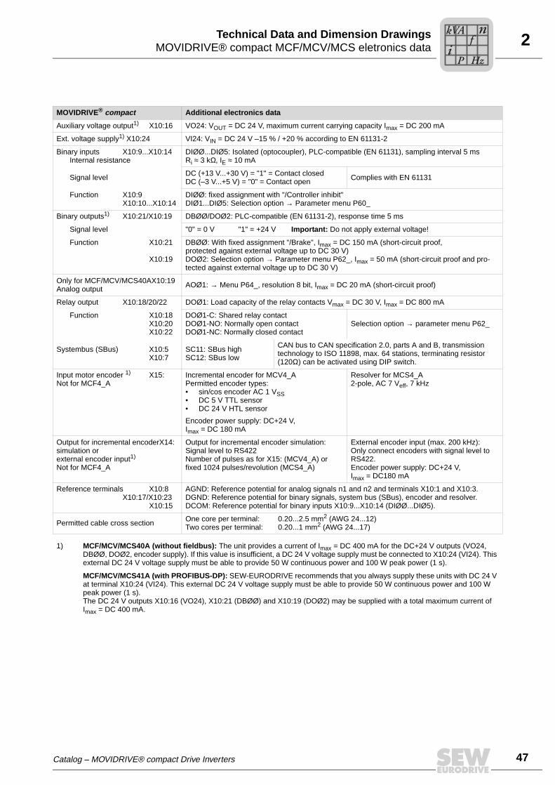
2MOVIDRIVE® compact MCF/MCV/MCS eletronics dataTechnical Data and Dimension Drawings
MOVIDRIVE® compact Additional electronics data
Auxiliary voltage output1) X10:16 VO24: VOUT = DC 24 V, maximum current carrying capacity Imax = DC 200 mA
Ext. voltage supply1) X10:24 VI24: VIN = DC 24 V –15 % / +20 % according to EN 61131-2
Binary inputs X10:9...X10:14Internal resistance
DIØØ...DIØ5: Isolated (optocoupler), PLC-compatible (EN 61131), sampling interval 5 msRi ≈ 3 kΩ, IE ≈ 10 mA
Signal level DC (+13 V...+30 V) = "1" = Contact closedDC (–3 V...+5 V) = "0" = Contact open Complies with EN 61131
Function X10:9X10:10...X10:14
DIØØ: fixed assignment with "/Controller inhibit"DIØ1...DIØ5: Selection option → Parameter menu P60_
Binary outputs1) X10:21/X10:19 DBØØ/DOØ2: PLC-compatible (EN 61131-2), response time 5 ms
Signal level "0" = 0 V "1" = +24 V Important: Do not apply external voltage!
Function X10:21
X10:19
DBØØ: With fixed assignment "/Brake", Imax = DC 150 mA (short-circuit proof, protected against external voltage up to DC 30 V)DOØ2: Selection option → Parameter menu P62_, Imax = 50 mA (short-circuit proof and pro-tected against external voltage up to DC 30 V)
Only for MCF/MCV/MCS40AX10:19Analog output AOØ1: → Menu P64_, resolution 8 bit, Imax = DC 20 mA (short-circuit proof)
Relay output X10:18/20/22 DOØ1: Load capacity of the relay contacts Vmax = DC 30 V, Imax = DC 800 mA
Function X10:18X10:20X10:22
DOØ1-C: Shared relay contactDOØ1-NO: Normally open contactDOØ1-NC: Normally closed contact
Selection option → parameter menu P62_
Systembus (SBus) X10:5X10:7
SC11: SBus highSC12: SBus low
CAN bus to CAN specification 2.0, parts A and B, transmission technology to ISO 11898, max. 64 stations, terminating resistor (120Ω) can be activated using DIP switch.
Input motor encoder 1) X15:Not for MCF4_A
Incremental encoder for MCV4_APermitted encoder types:• sin/cos encoder AC 1 VSS• DC 5 V TTL sensor• DC 24 V HTL sensor
Encoder power supply: DC+24 V, Imax = DC 180 mA
Resolver for MCS4_A2-pole, AC 7 Veff, 7 kHz
Output for incremental encoderX14:simulation orexternal encoder input1)
Not for MCF4_A
Output for incremental encoder simulation:Signal level to RS422Number of pulses as for X15: (MCV4_A) or fixed 1024 pulses/revolution (MCS4_A)
External encoder input (max. 200 kHz):Only connect encoders with signal level toRS422.Encoder power supply: DC+24 V, Imax = DC180 mA
Reference terminals X10:8X10:17/X10:23
X10:15
AGND: Reference potential for analog signals n1 and n2 and terminals X10:1 and X10:3.DGND: Reference potential for binary signals, system bus (SBus), encoder and resolver.DCOM: Reference potential for binary inputs X10:9...X10:14 (DIØØ...DIØ5).
Permitted cable cross section One core per terminal: 0.20...2.5 mm2 (AWG 24...12)Two cores per terminal: 0.20...1 mm2 (AWG 24...17)
1) MCF/MCV/MCS40A (without fieldbus): The unit provides a current of Imax = DC 400 mA for the DC+24 V outputs (VO24, DBØØ, DOØ2, encoder supply). If this value is insufficient, a DC 24 V voltage supply must be connected to X10:24 (VI24). This external DC 24 V voltage supply must be able to provide 50 W continuous power and 100 W peak power (1 s).
MCF/MCV/MCS41A (with PROFIBUS-DP): SEW-EURODRIVE recommends that you always supply these units with DC 24 V at terminal X10:24 (VI24). This external DC 24 V voltage supply must be able to provide 50 W continuous power and 100 W peak power (1 s).The DC 24 V outputs X10:16 (VO24), X10:21 (DBØØ) and X10:19 (DOØ2) may be supplied with a total maximum current of Imax = DC 400 mA.
Catalog – MOVIDRIVE® compact Drive Inverters
Pi
fkVA
Hz
n
47

48
2 OVIDRIVE® compact MCF/MCV/MCS eletronics dataechnical Data and Dimension Drawings
Front view of the MCF40A, MCF41A control unit
59894AXXFigure 8: Front view of the MCF40A, MCF41A control unit
X10 X10MCV40A MCV41A
REF1
REF2
SC11
SC12
DIØØ
DIØ2
DIØ4
DCOM
DGND
DOØ2
DBØØ
DGND
REF1
REF2
SC11
SC12
DIØØ
DIØ2
DIØ4
DCOM
DGND
DOØ2
DBØØ
DGND
AI11
AI12
AI21
AGND
DIØ1
DIØ3
DIØ5
VO24
DOØ1-C
DOØ1-NO
DOØ1-NC
VI24
AI11
AI12
AI21
AGND
DIØ1
DIØ3
DIØ5
VO24
DOØ1-C
DOØ1-NO
DOØ1-NC
VI24
1
3
5
7
9
11
13
15
17
19
21
23
1
3
5
7
9
11
13
15
17
19
21
23
2
4
6
8
10
12
14
16
18
20
22
24
2
4
6
8
10
12
14
16
18
20
22
24
1
5
6
9
PROFIBUS DPX30
RUN BUSFAULT
1
5
6
9
5
1
9
6
X15ENCODER IN
X14ENCODER I/O
1
5
6
9
5
1
9
6
X15ENCODER IN
X15ENCODER I/O
max 24V !
(EN 61131-2)
max 24V !
(EN 61131-2)
MT
Pi
fkVA
Hz
n
Catalog – MOVIDRIVE® compact Drive Inverters

2MOVIDRIVE® compact MCF/MCV/MCS eletronics dataTechnical Data and Dimension Drawings
Front view of the MCV/MCS40A, MCV/MCS41A control unit
59898AXXFigure 9: Front view of the MCV/MCS40A, MCV/MCS41A control unit
X10 X10MCF40A MCF41A
REF1
REF2
SC11
SC12
DIØØ
DIØ2
DIØ4
DCOM
DGND
DOØ2
DBØØ
DGND
REF1
SC11
SC12
DIØØ
DIØ2
DIØ4
DCOM
DGND
DOØ2
DBØØ
DGND
AI11
AI12
AI21
AGND
DIØ1
DIØ3
DIØ5
VO24
DOØ1-C
DOØ1-NO
DOØ1-NC
VI24
AI21
AGND
DIØ1
DIØ3
DIØ5
VO24
DOØ1-C
DOØ1-NO
DOØ1-NC
VI24
1
3
5
7
9
11
13
15
17
19
21
23
1
3
5
7
9
11
13
15
17
19
21
23
2
4
6
8
10
12
14
16
18
20
22
24
2
4
6
8
10
12
14
16
18
20
22
24
1
5
6
9
PROFIBUS DPX30
RUN BUSFAULT
max 24V !
(EN 61131-2)
max 24V !
(EN 61131-2)
Catalog – MOVIDRIVE® compact Drive Inverters
Pi
fkVA
Hz
n
49

50
2 OVIDRIVE® compact MCH electronics dataechnical Data and Dimension Drawings
2.6 MOVIDRIVE® compact MCH electronics data
MOVIDRIVE® compact Setpoint processing and speed ramps
MCH40A Version without fieldbus interface.
MCH41A Version with PROFIBUS-DP interface.
Protocol variantBaud rateConnection technologyBus terminator
Station addressName of the GSD fileDP ident. number
PROFIBUS DP to IEC 61158Automatic baud rate detection from 9.6 kbaud to 12 Mbaud9-pole sub D connector, pin assignment to IEC 61158Not integrated; connect using suitable PROFIBUS connector with terminating resistors that can be activated0 ... 125, adjustable via DIP switchesSEW_6003.GSD6003hex (24579dec)
MCH42A Version with INTERBUS fiber optic cable (LWL) interface.
Protocol variantBaud rateConnection technology
INTERBUS to EN 61158-2 with optically controlled LWL interface500 kBaud and 2 MBaud, can be selected via DIP switch4 F-SMA connectors (2 × remote bus input and 2 × remote bus output )
Valid for all versions
Voltage supply X10:1for setpoint input X10:6
REF1: DC+10 V +5 % / –0 %, Imax = DC 3 mAREF2: DC–10 V +0 % / –5 %, Imax = DC 3 mA
Reference voltages for setpoint potentio-meter
Setpoint input n1 X10:2/X10:3 AI11/AI12: Voltage or current input, can be set with S11 and P11_, sampling interval 1 ms
(Differential input)Operating mode AI11/AI12ResolutionInternal resistance
Voltage input:n1 = DC (0...+10 V) or DC (–10 V...0...+10 V)12 bitRi = 40 kΩ (external voltage supply)Ri = 20 kΩ (supply from REF1/REF2)
Current input:n1 = DC (0...20 mA or 4...20 mA)11 bitRi = 250 Ω
Setpoint input n2 X10:4TF/TH inputResolution
Analog input DC (0 ... 10 V) or optionally (→ P120) TF/TH inputwith response threshold at RTF ≥ 2.9 kΩ ± 10 %10 bit
Internal setpoints Parameter set 1: n11/n12/n13 = –5000...0...+5000 min–1
Parameter set 2: n21/n22/n23 = –5000...0...+5000 min–1
Time ranges of the speed rampsat ∆n = 3000 min–1
1st ramp t11/t21 Up: 0.0...2000 s Down: 0.0...2000 s2nd ramp t12/t22 Up = down: 0.0...2000 sStop ramp t13/t23 Down: 0...20 sEmergency ramp t14/t24 Down: 0...20 sMotor potentiometer t3 Up: 0.2...50 s Down: 0.2...50 s
MT
Pi
fkVA
Hz
n
Catalog – MOVIDRIVE® compact Drive Inverters

2MOVIDRIVE® compact MCH electronics dataTechnical Data and Dimension Drawings
MOVIDRIVE® compact Additional electronics data
Auxiliary voltage output1) X11:8 VO24: VOUT = DC 24 V, maximum current carrying capacity Imax = DC 200 mA
Ext. voltage supply1) X12:6 VI24: VIN = DC 24 V –15 % / +20 % to EN 61131-2
Binary inputs X11:1...X11:6Internal resistance
DIØØ...DIØ5: Isolated (optocoupler), PLC-compatible (EN 61131), sampling interval 5 msRi ≈ 3 kΩ, IE ≈ 10 mA
Signal level DC (+13 V...+30 V) = "1" = Contact closedDC (–3 V...+5 V) = "0" = Contact open Complies with EN 61131
Function X11:1X11:2...X11:6
DIØØ: fixed assignment with "/Controller inhibit"DIØ1...DIØ5: Selection option → parameter menu P60_
Binary outputs1) X12:1/X12:5 DBØØ/DOØ2: PLC-compatible (EN 61131-2), response time 5 ms
Signal level "0" = 0 V "1" = +24 V Important: Do not apply external voltage!
Function X12:1
X12:5
DBØØ: With fixed assignment "/Brake", Imax = DC 150 mA (short-circuit proof,protected against external voltage up to DC 30 V)DOØ2: Selection option → parameter menu P62_, Imax = DC 50 mA (short-circuit proof and protected against external voltage up to DC 30 V)
Analog output X12:5 AOØ1: → Menu P64_, resolution 8 bit, Imax = DC 20 mA (short-circuit proof)
Relay output X12:2/3/4 DOØ1: Load capacity of the relay contacts Vmax = DC 30 V, Imax =DC 800 mA
Function X12:2X12:3X12:4
DOØ1-C: Shared relay contactDOØ1-NO: Normally open contactDOØ1-NC: Normally closed contact
Selection option → parameter menu P62_
System bus (SBus) X10:7/10X10:8/11
SC11/21: SBus highSC12/22: SBus low
CAN bus to CAN specification 2.0, parts A and B, transmission technology to ISO 11898, max. 64 stations, terminating resistor (120Ω) can be activated using DIP switch.
Input motor encoder 1) X15: Permitted encoder types:• Hiperface encoder• sin/cos encoder AC 1 VSS• TTL sensor
Encoder power supply: DC + 12 V, Imax = DC 180 mA
Output for incremental encoder X14:simulation orexternal encoder input1)
Output for incremental encoder simulation:Signal level to RS422The number of pulses is:• 1024 pulses/revolution (Hiperface® encoder
on X15)• as at X15: Motor encoder input (sin/cos
encoder or TTL sensor on X15)
External encoder input (max. 200 kHz):Permitted encoder types:• Hiperface encoder• sin/cos encoder AC 1 VSS• TTL sensor
Encoder power supply: DC+12 V, Imax = DC 180 mA
Reference terminals X10:5X10:9/X11:9/X12:7
X11:7
AGND: Reference potential for analog signals n1 and n2 and terminals X10:1 and X10:6.DGND: Reference potential for binary signals, system bus (SBus), encoder and resolver.DCOM: Reference potential for binary inputs X10:9...X10:14 (DIØØ...DIØ5).
Permitted line cross section Only one core per terminal: 0.20...1.5 mm2 (AWG 24...16)Use right-angled crimping pliers with 1.5 mm2 (AWG 16)
1) MCH40A (without fieldbus): The unit provides a current of Imax = DC 400 mA for the DC+24 V outputs (VO24, DBØØ, DOØ2, encoder supply). If this value is insufficient, a DC 24 V voltage supply must be connected to X10:24 (VI24). This external DC 24 V voltage supply must be able to provide 50 W continuous power and 100 W peak power (1 s).
MCH41A (with PROFIBUS-DP) or MCH42A (with INTERBUS-LWL): SEW-EURODRIVE recommends that you always supply these units with DC 24 V at terminal X10:24 (VI24). This external DC 24 V voltage supply must be able to provide 50 W continuous power and 100 W peak power (1 s).The DC 24 V outputs X10:16 (VO24), X10:21 (DBØØ) and X10:19 (DOØ2) may be supplied with a total maximum current of Imax = DC 400 mA.
Catalog – MOVIDRIVE® compact Drive Inverters
Pi
fkVA
Hz
n
51

52
2 OVIDRIVE® compact MCH electronics dataechnical Data and Dimension Drawings
Front view of MCH42A control unit
59900AXXFigure 10: Front view of MCH42A control unit
V1
X14 E
ncoder
I/O
X15 E
ncoder
IN
X10
X11
X12
Remote INX30 IN
Remote INX31 OUT
Remote OUTX32 IN
Remote OUTX33 OUT
1234567891011
123456789
1234567
UL
CC
BA
RD
TR
FO
1F
O2 1
234567891011
123456789
1234567
REF1AI11AI12AI21AGNDREF2SC11SC12DGNDSC21SC22
DIØØDIØ1DIØ2DIØ3DIØ4DIØ5DCOMVO24DGND
DBØØDOØ1-CDOØ1-NODOØ1-NCDOØ2VI24DGND
X10
X11
X12
MCH 42A max 24V !
(EN 61131-2)
MT
Pi
fkVA
Hz
n
Catalog – MOVIDRIVE® compact Drive Inverters

2MOVIDRIVE®compact dimension drawingsTechnical Data and Dimension Drawings
2.7 MOVIDRIVE®compact dimension drawings
Dimension drawing for size 1 (0015 ... 0040-5A3 and 0015 ... 0037-2A3)
59816AXX
All dimensions in mm
* Power shield clamp
** Unit dimensions including connected power terminals
82
54
85
105
6
30
0
314
MCF/MCV/MCS: 155
MCH: 161
34
3**
*
NOTELeave at least 100 mm clearance above and below the unit to ensure optimum cooling.There is no need for clearance at the sides. You can line up the units directly next toone another.
Catalog – MOVIDRIVE® compact Drive Inverters
Pi
fkVA
Hz
n
53
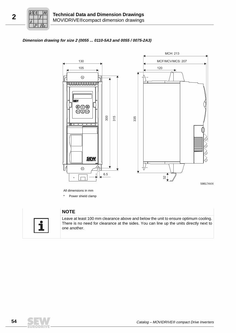
54
2 OVIDRIVE®compact dimension drawingsechnical Data and Dimension Drawings
Dimension drawing for size 2 (0055 ... 0110-5A3 and 0055 / 0075-2A3)
59817AXX
All dimensions in mm
* Power shield clamp
130
105
MCF/MCV/MCS: 207
300
315
335
6.5
32
120
*
MCH: 213
NOTELeave at least 100 mm clearance above and below the unit to ensure optimum cooling.There is no need for clearance at the sides. You can line up the units directly next toone another.
MT
Pi
fkVA
Hz
n
Catalog – MOVIDRIVE® compact Drive Inverters

2MOVIDRIVE®compact dimension drawingsTechnical Data and Dimension Drawings
Dimension drawing for size 3 (0150 ... 0300-503 and 0110 / 0150-203)
59818AXX
All dimensions in mm
46
5
44
5
7
105
200
173
MCF/MCV/MCS: 227
MCH: 233
NOTELeave at least 100 mm clearance above and below the unit to ensure optimum cooling.There is no need for clearance at the sides. You can line up the units directly next toone another.
Catalog – MOVIDRIVE® compact Drive Inverters
Pi
fkVA
Hz
n
55
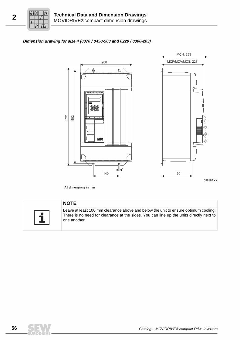
56
2 OVIDRIVE®compact dimension drawingsechnical Data and Dimension Drawings
Dimension drawing for size 4 (0370 / 0450-503 and 0220 / 0300-203)
59819AXX
All dimensions in mm
52
2
50
2
140
7
280
160
MCF/MCV/MCS: 227
MCH: 233
NOTELeave at least 100 mm clearance above and below the unit to ensure optimum cooling.There is no need for clearance at the sides. You can line up the units directly next toone another.
MT
Pi
fkVA
Hz
n
Catalog – MOVIDRIVE® compact Drive Inverters
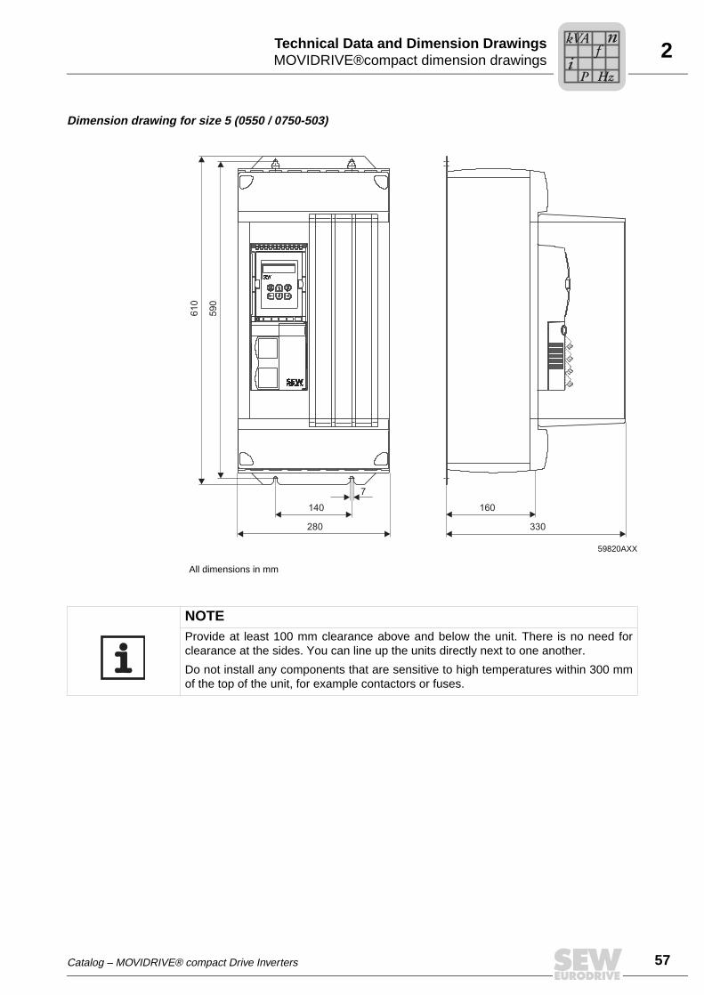
2MOVIDRIVE®compact dimension drawingsTechnical Data and Dimension Drawings
Dimension drawing for size 5 (0550 / 0750-503)
59820AXX
All dimensions in mm
610
590
140
7
280
160
330
NOTEProvide at least 100 mm clearance above and below the unit. There is no need forclearance at the sides. You can line up the units directly next to one another.
Do not install any components that are sensitive to high temperatures within 300 mmof the top of the unit, for example contactors or fuses.
Catalog – MOVIDRIVE® compact Drive Inverters
Pi
fkVA
Hz
n
57

58
2 OVIDRIVE® MDR60A regenerative power supply unitechnical Data and Dimension Drawings
2.8 MOVIDRIVE® MDR60A regenerative power supply unit
In MOVIDRIVE® drive inverters operating in regenerative mode (4Q operation), theMOVIDRIVE® MDR60A regenerative power supply unit can be used as an alternativeto braking resistors. The prerequisite is a powerful supply system. For more detailed in-formation, refer to the "MOVIDRIVE® MDR60A Regenerative Power Supply Unit" sys-tem manual. This system manual can be ordered from SEW-EURODRIVE.
MOVIDRIVE® MDR60A supplies the DC link circuit of the connected MOVIDRIVE®
drive inverter with electrical power from the supply system in motor operation and re-turns regenerative power to the supply system in regenerative operation.
UL approval UL and cUL approval has been granted for the entire MOVIDRIVE® MDR60A0370-503-00 and MDR60A0750-503-00 range of units. cUL is equivalent to CSA approval. TheMOVIDRIVE® MDR60A1320-503-00 unit does not have UL or cUL approval.
Protection and monitoring functions
• Monitoring and protection against thermal overload.
• Detection of power failure within one supply system half-wave.
• Overvoltage protection.
UL®C UL®
54512AXXFigure 11: MOVIDRIVE® MDR60A regenerative power supply units
MT
Pi
fkVA
Hz
n
Catalog – MOVIDRIVE® compact Drive Inverters

2MOVIDRIVE® MDR60A regenerative power supply unitTechnical Data and Dimension Drawings
Features of the regenerative power supply unit compared to an inverter with braking resistors
• Energy balance: Regenerative power is fed back into the supply system instead ofbeing converted into waste heat.
• Less installation work with several inverters (network and braking resistor connec-tions). However, a braking resistor is required to bring the drive to a controlled stopeven when there is a disruption in the supply system.
• Reduction in use of control cabinet space and fan power if the braking resistor waspreviously installed in the control cabinet.
General technical data
MOVIDRIVE® MDR60A 0370-503-00 (size 3)0750-503-00 (size 4)
1320-503-00 (size 6)
Interference immunity Complies with EN 61800-3 Meets EN 61000-6-1 and EN 61000-6-2
Interference emission with EMC-compliant installation
Complies with EN 61800-3• With NF085-503 line filter (size 3)• With NF150-503 line filter (size 4)
Meets EN 61000-6-4 with line filter NF300-503
Ambient temperature ϑUDerating ambient temperature
0 °C...+40 °CIN reduction: 3 % IN per K to max. 60 °C
0 °C...+40 °CIN reduction: 3 % IN per K to max. 55 °C
Climate class EN 60721-3-3, class 3K3
Storage temperature1) ϑL
1) In case of long-term storage, the unit must be connected to the mains voltage for at least 5 minutes every two years, otherwise theunit’s service life may be reduced.
–25 °C...+70 °C (EN 60721-3-3, class 3K3) –25 °C...+55 °C(EN 60721-3-3, class 3K3)
Cooling type (DIN 51751) Forced cooling(temperature-controlled fan, response threshold 50 °C)
Forced cooling(temperature-controlled fan, response threshold 45 °C)
Enclosure Size 3EN 60529 Size 4(NEMA 1)
IP20IP00 (power connections) IP10 (power connections)• With fitted plexiglass cover supplied as standard• With shrink tubing (not included in scope of
delivery)
IP20
Operating mode Continuous operation with 50 % overload capacity
Overvoltage category III according to IEC 60664-1 (VDE 0110-1)
Pollution class 2 according to IEC 60664-1 (VDE 0110-1)
Installation altitude There are no restrictions for heights ≤ 1,000 m.The following restrictions apply at heights ≥ 1,000 m:• From 1,000 m to max. 4,000 m:
– IN reduction by 1% per 100 m (330 ft)
• From 2,000 m to max. 4,000 m:– VN reduction by AC 6 V per 100 m
Over 2,000 m only overvoltage class 2; external mea-sures are required for overvoltage class 3. Overvoltage classes according to DIN VDE 0110-1.
h ≤ 1,000 m: No limitationFrom 1,000 m to max. 4,000 m:IN reduction: 0.5 % per 100 m
Catalog – MOVIDRIVE® compact Drive Inverters
Pi
fkVA
Hz
n
59

60
2 OVIDRIVE® MDR60A regenerative power supply unitechnical Data and Dimension Drawings
Technical data of the MOVIDRIVE® MDR60A regenerative power supply unit
MOVIDRIVE® MDR60A 0370-503-00 (size 3)
0750-503-00 (size 4)
1320-503-00(size 6)
Part number 826 658 1 826 556 9 827 952 7
INPUT
Supply voltage Vmains 3 × AC 380 V –10 % ... 3 × AC 500 V +10 %
Supply frequency fmains 50 Hz ... 60 Hz ±5 % 40 Hz ... 60 Hz ±10 %
Rated connected load PN 37 kW AC 66 A AC 260A
Rated supply current Imains(at Vmains = 3 × AC 400 V)
AC 66 A AC 117 A AC 260 A
DC LINK
Apparent output power SA(at Vmains = 3 × AC 380...500 V)
50 kVA 90 kVA 173 kVA
DC link voltage VDClink DC 560 V ... 780 V
Rated DC link current IDClink DC 70 A DC 141 A DC 340 A
Max. DC link current IDC_max DC 105 A DC 212 A DC 410 A
GENERAL INFORMATION
Power loss at PN PVmax 950 W 1,700 W 2,650 W
Cooling air consumption 180 m3/h 360 m3/h 700 m3/h
Connection for power terminals X1, X2(L1, L2, L3 for size 6)
Permitted tightening torquePermitted cable cross section
M6 screw with washer
3.5 Nm25 mm2 (AWG4)
M10 terminal studs
14 Nm70 mm2 (AWG2/0)
M10 terminal studs
3.5 Nm25 mm2 (AWG4)
Connection for DC link connection ±UG
Permitted cable cross sectionPermitted tightening torque
- - 150 mm2 (power supply connection) / 30 Nm1)
185 mm2 (DC link con-nection) / 32 Nm1)
Connection for electronics terminalsX3(X2 for size 6)
Permitted cable cross section:• One core per terminal: 0.20...2.5 mm2
(AWG24...13)• Two cores per terminal:0.25...1 mm2 (AWG23...17)
Permitted cable cross section:• 0.8...4 mm2
(AWG18...12)
Weight 16 kg 24 kg 90 kg
Dimensions W × H × D 200 × 465 × 221 mm 280 × 522 × 205 mm 380 × 937× 395 mm
Line choke (always required) ND085-013LN = 0.1 mHPart number 826 014 1
ND200-0033 LN = 0.03 mHPart number 826 579 8
Already installed
Line filter (optional) NF085-503, part number 827 415 0
NF150-503, part number 827 417 7
NF300-503, part number 827 419 3
For MOVIDRIVE® compact ...-5_3 0015 ... 0370 0015 ... 0750 0015 ... 0750
1) Important: Do not apply tightening torque directly at terminals L1, L2, L3 and ±UG; use a second wrench.
MT
Pi
fkVA
Hz
n
Catalog – MOVIDRIVE® compact Drive Inverters

2MOVIDRIVE® MDR60A regenerative power supply unitTechnical Data and Dimension Drawings
MDR60A dimen-sion drawings
Provide at least 100 mm clearance above and below the unit. There is no need for clear-ance at the sides. You can line up the units directly next to one another. With sizes 4and 6, do not install any components that are sensitive to high temperatures within300 mm of the top of the unit, for example contactors or fuses.
54260BXXFigure 12: Dimension drawing for MDR60A size 3, dimensions in mm
54261BXXFigure 13: Dimension drawing for MDR60A size 4, dimensions in mm
46
5
44
5
11 7
105
200 221
173
52
2
50
211 7
140
280 205
160
Catalog – MOVIDRIVE® compact Drive Inverters
Pi
fkVA
Hz
n
61

62
2 OVIDRIVE® MDR60A regenerative power supply unitechnical Data and Dimension Drawings
DC link connection
SEW-EURODRIVE recommends using the following cable sets for the DC link connec-tion. These cable sets offer the appropriate dielectric strength and are also color-coded.Color coding is necessary because cross-polarity and ground faults could cause irrepa-rable damage to the connected equipment.
The length of the cables restricts the DC link connection to the permitted length of 5 m.They can also be cut to length by the customer for connecting several units. The lugsfor connection to the regenerative power supply unit and an inverter are supplied withthe cable set. Use commercially available lugs for connecting additional inverters. Theinverters must then be connected to the regenerative power supply unit in star configu-ration.
54282BXXFigure 14: Dimension drawing for MDR60A size 6, dimensions in mm
395
85
11
0804
33
350
380
82
350
680
Cable set type DCP12A DCP13A DCP15A
Part number 814 567 9 814 250 5 814 251 3
For connecting MOVIDRIVE® 0015 ... 0110 0150 ... 0370 0450 ... 0750
NOTERefer to the "MOVIDRIVE® MDR60A Regenerative Power Supply Unit" system manualfor information on the DC link connection. This system manual can be ordered fromSEW-EURODRIVE.
MT
Pi
fkVA
Hz
n
Catalog – MOVIDRIVE® compact Drive Inverters

2IPOSplus®Technical Data and Dimension Drawings
-
2.9 IPOSplus®
Description IPOSplus® positioning and sequence control is integrated into every MOVIDRIVE®
inverter as standard. IPOSplus® can be used to execute control functions and positioningtasks either simultaneously or independently of one another.
IPOSplus® sequence control makes it possible to run a user program, regardless of theencoder feedback or the selected control mode (VFC, CFC, SERVO). In conjunctionwith encoder feedback (MCV, MCS, MCH), IPOSplus® positioning provides high-performance point-to-point positioning. The IPOSplus® program is written using theMOVITOOLS® software. The operating software or DBG11B keypad (startup in VFCmode only) can be used to start up the inverter, access parameters and changevariables.
Features • Program execution independent of encoder feedback and operating mode.
• The user program is continued even if a unit malfunction occurs (troubleshooting ispossible in the user program).
• Two user programs can be run in parallel and independently of one another (task 1,interrupt-capable, and task 2).
• The user programs programmed in the assembler can contain up to 800 programlines.
• User-friendly and comprehensive control options for the inverter.
• Extensive options for communication via system bus (SBus), RS-485, RS-232 andfieldbus (direct communication with MOVIMOT® is possible).
• Processing of digital and analog input/output signals.
Only with MCV/MCS/MCH
• Positioning with adjustable travel speed and positioning ramps.
• Feedforward for position, speed and torque control loops with minimized lag error.
• Two touch probe inputs.
• Ramp types LINEAR, SINE and SQUARE.
• Status and monitoring functions: Lag error monitoring, position signal, software andhardware limit switches.
• Eight reference travel types.
• Possibility of changing the target position, travel speed, positioning ramp and torquewhen movement is in progress.
• Possibility of "endless positioning."
• Override function.
Technical data
Max. program length of tasks 1 and 2 In total about 800 program lines (programmed in assembler)
Command processing time per program line Task 1: 1.0 ms; Task 2: 0.5 ms
Variables 512, of which 128 (0 ... 127) can be stored to non-volatile memory; range of values: -231...+(231-1)
Touch probe inputs 2 inputs, processing time < 100 µs
Sampling interval of digital and analog inputs 1...5 ms
Digital inputs/outputs 6 inputs / 3 outputs
Analog inputs/outputs 1 input (0...10 V, ±10 V, 0...20 mA, 4...20 mA)1)
1 input (0...10 V)1 output (0...20 mA, 4...20 mA)
1) Not for MCF41A
Catalog – MOVIDRIVE® compact Drive Inverters
Pi
fkVA
Hz
n
63

64
2 ptional DBG11B keypadechnical Data and Dimension Drawings
2.10 Optional DBG11B keypad
Description The keypad is needed for startup and service. The basic version of MOVIDRIVE® doesnot have a keypad and can be upgraded to include the keypad as an option.
Features • Illuminated plain text display, five languages can be set.
• Membrane keypad with 6 keys.
• Choice of quick menu, detailed parameter menu and startup menu in VFC mode(CFC and SERVO startup is not possible with the DBG11B).
• Can be plugged onto the inverter (TERMINAL slot).
• Connection via extension cable FKG11A (part number 822 101 4) possible.
• Enclosure IP40 (EN 60529)
Note The DBG11B keypad option and the USS21A/USB11A serial interface options areplugged into the same inverter slot (TERMINAL) and therefore cannot be used at thesame time.
Functions • Display process values and status.
• Status of binary inputs and outputs.
• Query error memory and error reset.
• Option to display and set the operating parameters and service parameters.
• Data backup and transfer of parameter sets to other MOVIDRIVE® units.
• User-friendly startup menu for VFC mode.
• Option to save a curve with electronic cam.
Dimension draw-ing for DBG11B and FKG11A
All dimensions in mm.
Keypad Language Part number
DBG11B-08 DE/EN/FR/ES/PT (German/English/French/Spanish/Portuguese) 824 154 6
DBG11B-09 EN/IT/SV/DA/FI (English/Italian/Swedish/Danish/Finnish) 824 155 4
DBG11B-11 ES/DE/EN/FR/PT (Spanish/German/English/French/Portuguese) 824 156 2
DBG11B-12 SV/EN/IT/DA/FI (Swedish/English/Italian/Danish/Finnish) 824 157 0
DBG11B-13 EN/ES/DE/FR/PT (English/Spanish/German/French/Portuguese) 824 158 9
DBG11B-14 FR/IT/ES/PT/EN (French/Italian/Spansih/Portuguese/English) 824 248 8
DBG11B-15 DE/EN/IT/ES/PT (German/English/Italian/Spanish/Portuguese) 824 423 5
59821AXX
[1] Cut-out for connector in mounting panel
[2] Communication cable for DBG11B - MOVIDRIVE®
[3] Holes for tapping screws 3.5 × 9.5 mm
110
12
75
40
85
12
0
18
00
82
21
01
4
28.51.5
FKG 11ADBG11B
[1][2]
[3]
OT
Pi
fkVA
Hz
n
Catalog – MOVIDRIVE® compact Drive Inverters
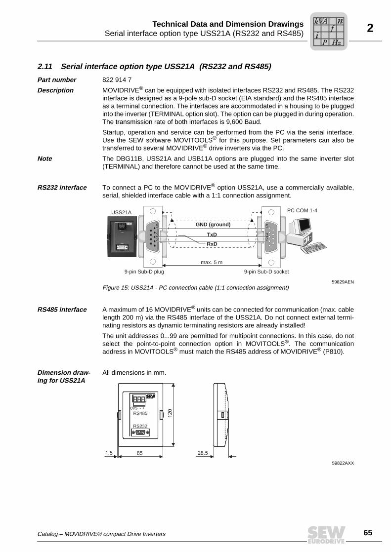
2Serial interface option type USS21A (RS232 and RS485)Technical Data and Dimension Drawings
2.11 Serial interface option type USS21A (RS232 and RS485)
Part number 822 914 7
Description MOVIDRIVE® can be equipped with isolated interfaces RS232 and RS485. The RS232interface is designed as a 9-pole sub-D socket (EIA standard) and the RS485 interfaceas a terminal connection. The interfaces are accommodated in a housing to be pluggedinto the inverter (TERMINAL option slot). The option can be plugged in during operation.The transmission rate of both interfaces is 9,600 Baud.
Startup, operation and service can be performed from the PC via the serial interface.Use the SEW software MOVITOOLS® for this purpose. Set parameters can also betransferred to several MOVIDRIVE® drive inverters via the PC.
Note The DBG11B, USS21A and USB11A options are plugged into the same inverter slot(TERMINAL) and therefore cannot be used at the same time.
RS232 interface To connect a PC to the MOVIDRIVE® option USS21A, use a commercially available,serial, shielded interface cable with a 1:1 connection assignment.
RS485 interface A maximum of 16 MOVIDRIVE® units can be connected for communication (max. cablelength 200 m) via the RS485 interface of the USS21A. Do not connect external termi-nating resistors as dynamic terminating resistors are already installed!
The unit addresses 0...99 are permitted for multipoint connections. In this case, do notselect the point-to-point connection option in MOVITOOLS®. The communicationaddress in MOVITOOLS® must match the RS485 address of MOVIDRIVE® (P810).
Dimension draw-ing for USS21A
All dimensions in mm.
59829AENFigure 15: USS21A - PC connection cable (1:1 connection assignment)
RxD
TxD2233
55
max. 5 m
USS21A PC COM 1-4
55
3322 2
3
55
32
9-pin Sub-D socket9-pin Sub-D plug
GND (ground)
59822AXX
85
12
0
RS232
RS4850V5 - +
28.51.5
Catalog – MOVIDRIVE® compact Drive Inverters
Pi
fkVA
Hz
n
65

66
2 nterface adapter type USB11A / option DKG11Aechnical Data and Dimension Drawings
2.12 Interface adapter type USB11A / option DKG11A
Part number • 824 831 1 Interface adapter USB11A
• 819 558 7 Serial interface cable DKG11A
Description Option USB11A enables a PC or laptop with a USB interface to be connected to theTERMINAL slot of MOVIDRIVE® compact. The USB11A interface adapter supportsUSB1.1 and USB2.0.
Scope of delivery • The scope of delivery for the USB11A includes:
– USB11A interface adapter– USB connection cable PC - USB11A (type USB A-B)– CD-ROM with drivers and MOVITOOLS®
• The USB11A interface adapter supports USB 1.1 and USB 2.0.
• The scope of delivery for the USB11A does not include:
– DKG11A connection cable (length 3 m, part number 819 558 7) for connectingMOVIDRIVE® compact - USB11A.
Connecting MOVIDRIVE® - USB11A - PC
• MOVIDRIVE® compact is connected to USB11A (cable RJ10-TERMINAL) using theserial interface cable type DKG11A (length 3 m, part number 819 558 7).
• USB11A is connected to the PC using a commercially available, shielded USBconnection cable type USB A-B.
Dimension drawing
Technical data
55732BXXFigure 16: USB11A dimension drawing, dimensions in mm
92.525
90
43
USB11A
Part number 824 831 1
Ambient temperature 0 °C... 40 °C
Storage temperature –25 °C ... +70 °C (according to EN 60721-3-3, class 3K3)
Enclosure IP20
Weight 300 g
Dimensions 92.5 x 43 x 25 mm
IT
Pi
fkVA
Hz
n
Catalog – MOVIDRIVE® compact Drive Inverters

2DC 5 V encoder supply type DWI11ATechnical Data and Dimension Drawings
2.13 DC 5 V encoder supply type DWI11A
Part number 822 759 4
Description If you are using an incremental encoder with a DC 5 V encoder power supply, install theDC 5 V encoder power supply option type DWI11A between the inverter and the incre-mental encoder. This option provides a regulated DC 5 V power supply for the encoder.For this purpose, the DC 12 V power supply for the encoder inputs is converted toDC 5 V by means of a voltage controller. A sensor line is used to measure the supplyvoltage at the encoder and compensate the voltage drop along the encoder cable.
Incremental encoders with DC 5 V encoder power supply may not be connected directlyto the encoder inputs X14: and X15:. This would cause irreparable damage to the en-coder.
Recommendation Use prefabricated cables from SEW for the encoder connection.
Dimension drawing
The DWI11A option is mounted on a support rail (EN 50022-35 × 7.5) in the control cab-inet.
Technical data
NOTEIf a short circuit occurs in the sensor cable, the connected encoder may be exposed toa voltage higher than permitted.
01315CXXFigure 17: DWI11A dimension drawing, dimensions in mm
68
73
5
22.5
75
X2:
Enc
oder
X1:
MO
VID
RIV
E
DWI
DC 5 V encoder power supply option type DWI11A
Part number 822 759 4
Voltage input DC 10...30 V, Imax = DC 120 mA
Encoder power supply DC +5 V (up to Vmax ≈ +10 V), Imax = DC 300 mA
Max. line length that can be connected
100 m totalUse a shielded twisted-pair cable (A and A, B and B, C and C) for connecting the encoder to the DWI11A and the DWI11A to MOVIDRIVE®.
Catalog – MOVIDRIVE® compact Drive Inverters
Pi
fkVA
Hz
n
67

68
2 raking resistors type BW... / BW...-T / BW...-Pechnical Data and Dimension Drawings
2.14 Braking resistors type BW... / BW...-T / BW...-P
General information
• Braking resistors BW... / BW...-T and BW...-P are adapted to the technical charac-teristics of MOVIDRIVE® drive inverters.
• Plan for a reduction of power of 4 % per 10 K below an ambient temperature of45 °C. Do not exceed a maximum ambient temperature of 80 °C.
Flat-type braking resistors
• Protection against contact (IP54)
• Internal thermal overload protection (non-replaceable fuse)
• Touch guard and mounting rail attachment available from SEW as accessories
Wire and grid resistors
• Perforated sheet cover (IP20) open to mounting surface
• The short-term load capacity of the wire and grid resistors is higher than in the flat-type braking resistors (→ MOVIDRIVE® compact system manual, section "Selectingthe braking resistor")
• A temperature switch is integrated in the BW...-T braking resistor
• A thermal overcurrent relay is integrated in the BW...-P braking resistor
SEW-EURODRIVE recommends implementing additional protection against overloadfor the wire and grid resistors by using a bimetallic relay with trip characteristics of tripclass 10 or 10A (in accordance with EN 60947-4-1). Set the trip current to the value IF(→ following tables). Do not use electronic or electromagnetic fuses because these canbe triggered even in case of short-term excess currents that are still within the tolerancerange.
For braking resistors in the BW..-T / BW...-P series, you can connect the integrated tem-perature sensor using a 2-core, shielded cable as an alternative to a bimetallic relay.The BW...-T and BW...-P braking resistors can be connected from the front or the back(→ dimension drawing for BW... / BW...-T / BW...-P braking resistors). Use filler plugsfor tapped holes that are not connected.
The resistor surfaces will get very hot under a load of PN. Make sure that you select aninstallation site that will accommodate these high temperatures. Braking resistors areusually mounted on the control cabinet roof.
The performance data listed in the tables below shows the load capacity of the brakingresistors according to their cyclic duration factor (cyclic duration factor = cdf of the brak-ing resistor in % in relation to a cycle duration ≤ 120 s).
UL and cUL approval
Type BW... braking resistors are UL and cUL approved in conjunction withMOVIDRIVE® compact drive inverters. SEW-EURODRIVE can provide proof ofapproval on request. The BW...-T and BW...-P braking resistors have cRUus approvalindependent of the MOVIDRIVE® inverters.
BT
Pi
fkVA
Hz
n
Catalog – MOVIDRIVE® compact Drive Inverters

2Braking resistors type BW... / BW...-T / BW...-PTechnical Data and Dimension Drawings
Parallel connection
Two braking resistors with the same value must be connected in parallel for some in-verter/resistor combinations. In this case, the trip current must be set on the bimetallicrelay to twice the value of IF entered in the table. For the BW...-T / BW...-P braking re-sistors, the temperature switch / overcurrent relay must be connected in series.
Assignment to AC 400/500 V units (...-5_3)
Braking resistor type BW... BW100-005 BW100-006 BW168 BW268
Part number 826 269 1 821 701 7 820 604 X 820 715 1
Braking resistor type BW...-T BW100-006-T BW168-T BW268-T
Part number 1 820 419 8 1 820 133 4 1 820 417 1
Cont. braking power (= 100 % cdf)Load capacity 50 % cdf1)
at 25 % cdf12 % cdf6 % cdf
1) cdf = cyclic duration factor of the braking resistor based on a cycle duration TD ≤ 120 s.
0.45 kW0.60 kW0.83 kW1.11 kW2.00 kW
0.6 kW1.1 kW1.9 kW3.6 kW5.7 kW
0.8 kW1.4 kW2.6 kW4.8 kW7.6 kW
1.2 kW2.2 kW3.8 kW7.2 kW11 kW
Observe the regenerative power limit of the inverter!(= 150 % of the recommended motor power → Technical Data)
Resistance value RBW 100 Ω ±10 % 68 Ω ±10 %
Trip current (of F16) IF 0.8 ARMS 2.4 ARMS 3.4 ARMS 4.2 ARMS
Design Flat design Wire resistor on ceramic core Wire resistor on ceramic core
Connections/tightening torque Cable
Ceramic terminals 2.5 mm2 (AWG13)0.5 Nm
Ceramic terminals 2.5 mm2 (AWG13)0.5 Nm
Enclosure IP54 IP20 (when installed) IP20 (when installed)
Ambient temperature ϑU –20 °C ... +40 °C
Type of cooling KS = self-cooling
For MOVIDRIVE® 0015 ... 0022 0015 ... 0040 0015 ... 0040 0015 ... 0040
Catalog – MOVIDRIVE® compact Drive Inverters
Pi
fkVA
Hz
n
69

70
2 raking resistors type BW... / BW...-T / BW...-Pechnical Data and Dimension Drawings
Braking resistor type BW... BW147 BW247 BW347 BW039-012
Part number 820 713 5 820 714 3 820 798 4 821 689 4
Braking resistor type BW...-T BW147-T BW247-T BW347-T BW039-012-T BW039-026-T BW039-050-T
Part number 1 820 134 2 1 820 084 2 1 820 135 0 1 820 136 9 1 820 415 5 1 820 137 7
Cont. braking power (= 100 % cdf)Load capacity 50 % cdf1)
at 25 % cdf12 % cdf6 % cdf
1.2 kW2.2 kW3.8 kW7.2 kW11 kW
2.0 kW3.6 kW6.4 kW12 kW19 kW
4.0 kW7.2 kW
12.8 kW20 kW2)
20 kW2)
1.2 kW2.1 kW3.8 kW7.2 kW11.4 kW
2.6 kW4.7 kW8.3 kW
15.6 kW24.0 kW2)
5.0 kW8.5 kW
15.0 kW24.0 kW2)
24.0 kW2)
Observe the regenerative power limit of the inverter!(= 150 % of the recommended motor power → Technical Data)
Resistance value RBW 47 Ω ±10 % 39 Ω ±10 %
Trip current (of F16) IF 5 ARMS 6.5 ARMS 9.2 ARMS 5.5 ARMS 8.1 ARMS 11.3 ARMS
Design Wire resistor on ceramic core Grid resistor
Connections/tightening torque
Ceramic terminals 2.5 mm2 (AWG13) / 0.5 NmBW347-T: Ceramic terminals 10 mm2 (AWG8) / 1.6 Nm
M8 stud /6 Nm
Enclosure IP20 (when installed)
Ambient temperature ϑU –20 °C ... +40 °C
Type of cooling KS = self-cooling
For MOVIDRIVE® 0055/0075 0110
1) cdf = cyclic duration factor of the braking resistor based on a cycle duration TD ≤ 120 s.
2) Physical power limit due to DC link voltage and resistance value.
Braking resistor type BW... BW018-015
Part number 821 684 3
Braking resistor type BW..-T/-P BW018-015-P BW018-035-T BW018-075-T BW915-T
Part number 1 820 416 3 1 820 138 5 1 820 139 3 1 820 413 9
Cont. braking power (= 100 % cdf)Load capacity 50 % cdf1)
at 25 % cdf12 % cdf6 % cdf
1.5 kW2.5 kW4.5 kW6.7 kW11.4 kW
3.5 kW5.9 kW
10.5 kW15.7 kW26.6 kW
7.5 kW12.7 kW22.5 kW33.7 kW
52.2 kW2)
16 kW27.2 kW48 kW
62.7 kW2)
62.7 kW2)
Observe the regenerative power limit of the inverter!(= 150 % of the recommended motor power → Technical Data)
Resistance value RBW 18 Ω ±10 % 15 Ω ±10 %
Trip current (of F16) IF 9.1 ARMS 13.9 ARMS 20.4 ARMS 32.6 ARMS
Design Wire resistor on ceramic core Steel-grid resistor
Connections/tightening torque
BW018-015: Ceramic terminals
2.5 mm2 (AWG13) /0.5 Nm
BW018-015-P: Terminal
2.5 mm2 (AWG13) /1 Nm
M8 bolt / 6 Nm
Enclosure IP20 (when installed)
Ambient temperature ϑU –20 °C ... +40 °C
Type of cooling KS = self-cooling
For MOVIDRIVE® 0150/0220 and 2 × parallel for 0370/04503) 0220
1) cdf = cyclic duration factor of the braking resistor based on a cycle duration TD ≤ 120 s.
2) Physical power limit due to DC link voltage and resistance value.
3) When connected in parallel, the load capacity and trip current are doubled.
BT
Pi
fkVA
Hz
n
Catalog – MOVIDRIVE® compact Drive Inverters

2Braking resistors type BW... / BW...-T / BW...-PTechnical Data and Dimension Drawings
Braking resistor type BW...- BW012-025
Part number 821 680 0
Braking resistor type BW..-T/-P BW012-025-P BW012-050T BW012-100-T BW106-T BW206-T
Part number 1 820 414 7 1 820 140 7 1 820 141 5 1 820 083 4 1 820 412 0
Cont. braking power (= 100 % cdf)Load capacity 50 % cdf1)
at 25 % cdf12 % cdf6 % cdf
2.5 kW4.2 kW7.5 kW11.2 kW19.0 kW
5.0 kW8.5 kW
15.0 kW22.5 kW38.0 kW
10 kW17 kW30 kW45 kW76 kW
13.5 kW23 kW40 kW61 kW
102 kW
18 kW30.6 kW54 kW81 kW
136.8 kW
Observe the regenerative power limit of the inverter!(= 150 % of the recommended motor power → Technical Data)
Resistance value RBW 12 Ω ±10 % 6 Ω ±10 %
Trip current (of F16) IF 14.4 ARMS 20.4 ARMS 28.8 ARMS 47.4 ARMS 54.7 ARMS
Design Steel-grid resistor
Connections/tightening torque
Ceramic terminals 2.5 mm2 (AWG13) / 0.5 NmBW012-025-P: Terminals 4 mm2 (AWG12) / 1 Nm M8 bolt / 6 Nm
Enclosure IP20 (when installed)
Ambient temperature ϑU –20 °C ... +40 °C
Type of cooling KS = self-cooling
For MOVIDRIVE® 0300 0370...0750
1) cdf = cyclic duration factor of the braking resistor based on a cycle duration TD ≤ 120 s.
Catalog – MOVIDRIVE® compact Drive Inverters
Pi
fkVA
Hz
n
71

72
2 raking resistors type BW... / BW...-T / BW...-Pechnical Data and Dimension Drawings
Assignment to AC 230 V units (...-2_3)
Technical data for braking resistors BW...-T / BW...-P
Braking resistor type BW... BW039-003
BW039-006
BW039-012
BW027-006
BW027-012
Part number 821 687 8 821 688 6 821 689 4 822 422 6 822 423 4
Braking resistor type BW...T/...P BW039-012-T
BW039-026-T
BW018-015-P
BW018-035-T
Part number 1 820 136 9 1 820 415 5 1 820 416 3 1 820 138 5
Cont. braking power (= 100 % cdf)Load capacity 50 % cdf1)
at 25 % cdf12 % cdf6 % cdf
1) cdf = cyclic duration factor of the braking resistor based on a cycle duration TD ≤ 120 s.
0.3 kW0.5 kW1.0 kW1.8 kW2.8 kW
0.6 kW1.1 kW1.9 kW3.6 kW5.7 kW
1.2 kW2.1 kW3.8 kW
6.0 kW2)
6.0 kW2)
2) Physical power limit due to DC link voltage and resistance value.
2.6 kW4.6 kW
6.0 kW2)
6.0 kW2)
6.0 kW2)
0.6 kW1.1 kW1.9 kW3.6 kW5.7 kW
1.2 kW2.1 kW3.8 kW7.2 kW
8.7 kW2)
1.5 kW2.5 kW4.5 kW6.7 kW11.4 kW
3.5 kW5.9 kW
10.5 kW13.0 kW2)
13.0 kW2)
Observe the regenerative power limit of the inverter!(= 150 % of the recommended motor power → Technical Data)
Resistance value RBW 39 Ω ±10 % 27 Ω ±10 % 18 Ω ±10 %
Trip current (of F16) IF 2.7 ARMS 3.9 ARMS 5.5 ARMS 8.1 ARMS 4.7 ARMS 6.6 ARMS 9.1 ARMS 13.9 ARMS
Design Wire resistor Steel-grid resistor
Connections/tightening torque
Ceramic terminals 2.5 mm2 (AWG12) /0.5 Nm
M8 stud /6 Nm
Enclosure IP20 (when installed)
Ambient temperature ϑU –20 °C ... +40 °C
Type of cooling KS = self-cooling
For MOVIDRIVE® 0015/0022 0015...0037 2 × parallel with 01103)
3) When connected in parallel, the load capacity and trip current are doubled.
Braking resistor type BW...T BW018-075-T BW915-T BW012-025-T BW012-050-T BW012-100-T BW106-T BW206-T
Part number 1 820 139 3 1 820 413 9 1 820 414 7 1 820 140 7 1 820141 5 1 820 083 4 1 820 4120
Cont. braking power (= 100 % cdf)Load capacity 50 % cdf1)
at 25 % cdf12 % cdf6 % cdf
7.5 kW12.7 kW
13.0 kW2)
13.0 kW2)
13.0 kW2)
15.6 kW2)
15.6 kW2)
15.6 kW2)
15.6 kW2)
15.6 kW2)
2.5 kW4.2 kW7.5 kW11.2 kW19.0 kW
5.0 kW8.5 kW
15.0 kW19.6 kW2)
19.6 kW2)
10 kW17 kW
19.6 kW2)
19.6 kW2)
19.6 kW2)
13.5 kW23 kW
39.2 kW2)
39.2 kW2)
39.2 kW2)
18 kW30.6 kW
39.2 kW2)
39.2 kW2)
39.2 kW2)
Observe the regenerative power limit of the inverter!(= 150 % of the recommended motor power → Technical Data)
Resistance value RBW 18 Ω ±10 % 15 Ω±10 % 12 Ω ±10 % 6 Ω ±10 %
Trip current (of F16) IF 20.4 ARMS 32.6 ARMS 14.4 ARMS 20.4 ARMS 28.8 ARMS 47.4 ARMS 54.7 ARMS
Design Steel-grid resistor
Connections/tightening torque
M8 stud /6 Nm
Enclosure IP20 (when installed)
Ambient temperature ϑU –20 °C ... +40 °C
Type of cooling KS = self-cooling
For MOVIDRIVE® 2 × parallel with 01103) 0055/0075 0150 and 2 × parallel with 0220/03003)
1) cdf = cyclic duration factor of the braking resistor based on a cycle duration TD ≤ 120 s.
2) Physical power limit due to DC link voltage and resistance value.
3) When connected in parallel, the load capacity and trip current are doubled.
BW...-T / BW...-P
Connection cross section for signal contact 1 x 2.5 mm2
Switching capability of the thermostat’s signal contact • DC 2 A / DC 24 V (DC11)• AC 2 A / AC 230V (AC11)
Switch contact (NC) according to EN 61800-5-1
BT
Pi
fkVA
Hz
n
Catalog – MOVIDRIVE® compact Drive Inverters

2Braking resistors type BW... / BW...-T / BW...-PTechnical Data and Dimension Drawings
Dimension drawings for braking resistors BW... / BW...-T / BW...-P
60021AXX
BW... :• 1 = Flat design
The connecting lead is 500 mm long. The scope of delivery includes four M4 stud bolts each of type 1 and 2.
• 2 = Grid resistor• 3 = Wire resistor• 4 = Wire resistor with
temperature switch (-T/-P)Cable entry (X) is possi-ble from both sides.
Type BW... Mounting position
Main dimensions [mm] Fastening parts [mm] Cable gland Weight [kg]
BW..-T/ BW...-P A B C a b/c d
BW106-T 2 795 270 490 770 380 10.5 - 32
BW206-T 2 995 270 490 970 380 10.5 - 40
BW012-025 2 295 260 490 270 380 10.5 - 8.0
BW012-025-P1) 2 295 260 490 270 380 10.5 M12 + M25 8.0
BW012-050-T 2 395 260 490 370 380 10.5 - 12
BW012-100-T 2 595 270 490 570 380 10.5 - 21
BW915-T 2 795 270 490 770 380 10.5 - 30
BW018-015 3 620 120 92 544 64 6.5 PG11 4.0
BW018-015-P 4 649 120 185 530 150 6.5 M12 + M25 5.8
BW018-035-T 2 295 270 490 270 380 10.5 - 9.0
BW018-075-T 2 595 270 490 570 380 10.5 - 18.5
BW027-006 3 486 120 92 430 64 6.5 PG11 2.2
BW027-012 3 486 120 185 426 150 6.5 PG11 4.3
BW039-003 3 286 120 92 230 64 6.5 PG11 1.5
BW039-006 3 486 120 92 430 64 6.5 PG11 2.2
BW039-012 3 486 120 185 426 150 6.5 PG11 4.3
BW039-012-T 4 549 120 185 426 150 6.5 M12 + M25 4.9
BW039-026-T 4 649 120 275 530 240 6.5 M12 + M25 7.5
BW039-050-T 2 395 260 490 370 380 10.5 - 12
BW147 3 465 120 185 426 150 6.5 PG13.5 4.3
BW147-T 4 549 120 185 426 150 6.5 M12 + M25 4.9
BW247 3 665 120 185 626 150 6.5 PG13.5 6.1
BW247-T 4 749 120 185 626 150 6.5 M12 + M25 9.2
BW347 3 670 145 340 630 300 6.5 PG13.5 13.2
BW347-T 4 749 210 185 630 150 6.5 M12 + M25 12.4
BW168 3 365 120 185 326 150 6.5 PG13.5 3.5
BW168-T 4 449 120 185 326 150 6.5 M12 + M25 3.6
BW268 3 465 120 185 426 150 6.5 PG13.5 4.3
BW268-T 4 549 120 185 426 150 6.5 M12 + M25 4.9
BW100-005 1 216 80 15 204 60 – - 0.6
BW100-006 4 486 120 92 430 64 6.5 PG11 2.2
BW100-006-T 4 549 120 92 430 80 6.5 M12 + M25 3.0
a
b
6
1012
1 2
M4
1
43
CBA
2
a 10d
cA C
B
ac
d
B
C A
3551)
A
a M25
M12C
X
c 8
B
Catalog – MOVIDRIVE® compact Drive Inverters
Pi
fkVA
Hz
n
73
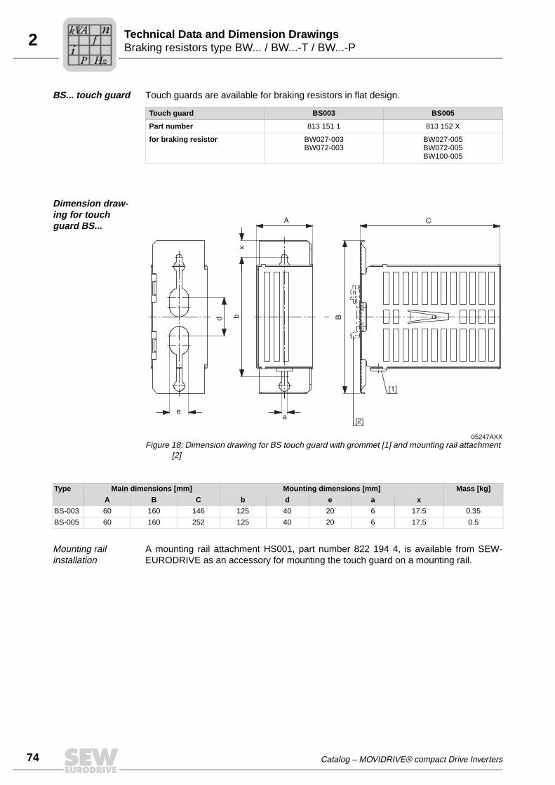
74
2 raking resistors type BW... / BW...-T / BW...-Pechnical Data and Dimension Drawings
BS... touch guard Touch guards are available for braking resistors in flat design.
Dimension draw-ing for touch guard BS...
Mounting rail installation
A mounting rail attachment HS001, part number 822 194 4, is available from SEW-EURODRIVE as an accessory for mounting the touch guard on a mounting rail.
Touch guard BS003 BS005
Part number 813 151 1 813 152 X
for braking resistor BW027-003BW072-003
BW027-005BW072-005BW100-005
05247AXXFigure 18: Dimension drawing for BS touch guard with grommet [1] and mounting rail attachment
[2]
Type Main dimensions [mm] Mounting dimensions [mm] Mass [kg]
A B C b d e a x
BS-003 60 160 146 125 40 20 6 17.5 0.35
BS-005 60 160 252 125 40 20 6 17.5 0.5
BT
Pi
fkVA
Hz
n
Catalog – MOVIDRIVE® compact Drive Inverters

2Braking resistors type BW... / BW...-T / BW...-PTechnical Data and Dimension Drawings
DKB11A heat sink for brake resistors in flatpack design
Part number 814 345 5
Description The DKB11A heat sink provides a space-saving means of mounting braking resistors inflatpack design (BW072-005, BW100-005) under MOVIDRIVE® size 1 (400/500 V units:0015...0040; 230 V units: 0015...0037). The resistor is inserted into the heat sink andattached using the screws supplied (M4 × 20).
Dimension drawing
1) Mounting surface for the braking resistor
2) Retaining screws are not included in the delivery scope
60063AENFigure 19: Dimension drawing for DKB11A heat sink, all dimensions in mm
814 345 5
BW...-005
BW...-003
300
315
85
105
10
185
30
9
M4 x 202)4 x M5 x 12
PE screw M5
4 x spacer bolts4 x pan head screws
Catalog – MOVIDRIVE® compact Drive Inverters
Pi
fkVA
Hz
n
75
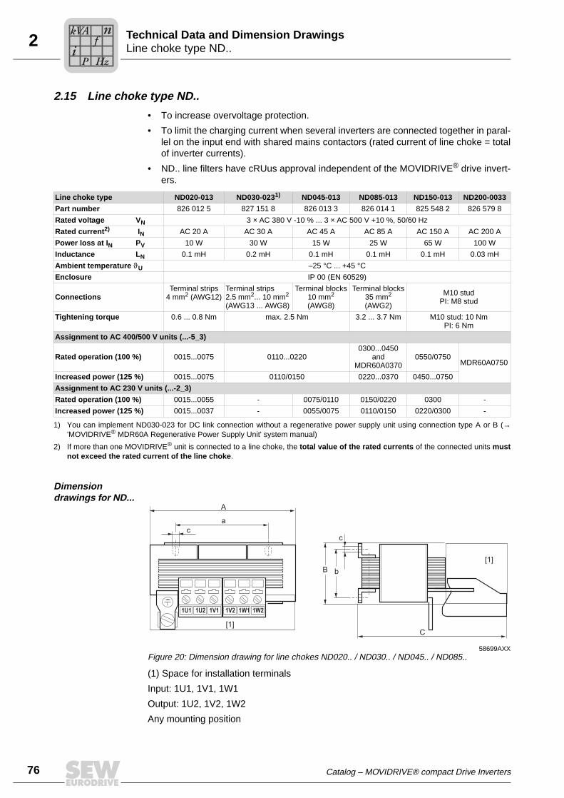
76
2 ine choke type ND..echnical Data and Dimension Drawings
2.15 Line choke type ND..
• To increase overvoltage protection.
• To limit the charging current when several inverters are connected together in paral-lel on the input end with shared mains contactors (rated current of line choke = totalof inverter currents).
• ND.. line filters have cRUus approval independent of the MOVIDRIVE® drive invert-ers.
Dimension drawings for ND...
(1) Space for installation terminals
Input: 1U1, 1V1, 1W1
Output: 1U2, 1V2, 1W2
Any mounting position
Line choke type ND020-013 ND030-0231) ND045-013 ND085-013 ND150-013 ND200-0033
Part number 826 012 5 827 151 8 826 013 3 826 014 1 825 548 2 826 579 8
Rated voltage VN 3 × AC 380 V -10 % ... 3 × AC 500 V +10 %, 50/60 Hz
Rated current2) IN AC 20 A AC 30 A AC 45 A AC 85 A AC 150 A AC 200 A
Power loss at IN PV 10 W 30 W 15 W 25 W 65 W 100 W
Inductance LN 0.1 mH 0.2 mH 0.1 mH 0.1 mH 0.1 mH 0.03 mH
Ambient temperature ϑU –25 °C ... +45 °C
Enclosure IP 00 (EN 60529)
ConnectionsTerminal strips
4 mm2 (AWG12)Terminal strips2.5 mm2... 10 mm2 (AWG13 ... AWG8)
Terminal blocks10 mm2 (AWG8)
Terminal blocks35 mm2 (AWG2)
M10 studPI: M8 stud
Tightening torque 0.6 ... 0.8 Nm max. 2.5 Nm 3.2 ... 3.7 Nm M10 stud: 10 NmPI: 6 Nm
Assignment to AC 400/500 V units (...-5_3)
Rated operation (100 %) 0015...0075 0110...02200300...0450
and MDR60A0370
0550/0750MDR60A0750
Increased power (125 %) 0015...0075 0110/0150 0220...0370 0450...0750
Assignment to AC 230 V units (...-2_3)
Rated operation (100 %) 0015...0055 - 0075/0110 0150/0220 0300 -
Increased power (125 %) 0015...0037 - 0055/0075 0110/0150 0220/0300 -
1) You can implement ND030-023 for DC link connection without a regenerative power supply unit using connection type A or B (→'MOVIDRIVE® MDR60A Regenerative Power Supply Unit' system manual)
2) If more than one MOVIDRIVE® unit is connected to a line choke, the total value of the rated currents of the connected units mustnot exceed the rated current of the line choke.
58699AXXFigure 20: Dimension drawing for line chokes ND020.. / ND030.. / ND045.. / ND085..
a
cc
C
A
[1]
[1]
1U1 1U2 1V1 1V2 1W1 1W2
B b
LT
Pi
fkVA
Hz
n
Catalog – MOVIDRIVE® compact Drive Inverters
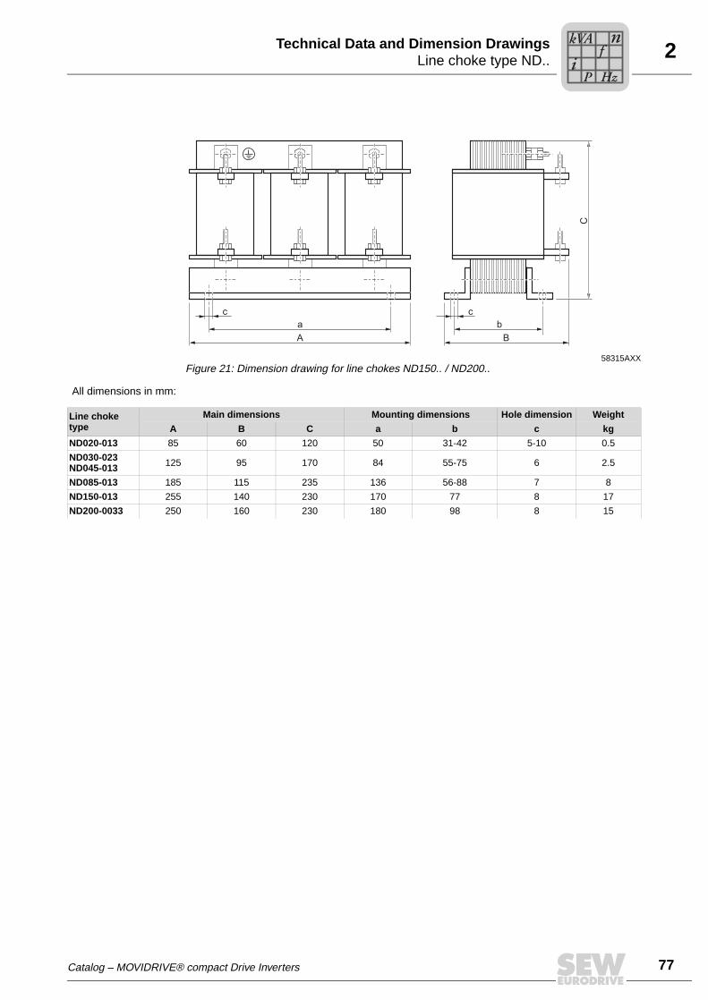
2Line choke type ND..Technical Data and Dimension Drawings
58315AXXFigure 21: Dimension drawing for line chokes ND150.. / ND200..
Ba
c cb
C
A
All dimensions in mm:
Line choke type
Main dimensions Mounting dimensions Hole dimension Weight
A B C a b c kg
ND020-013 85 60 120 50 31-42 5-10 0.5
ND030-023ND045-013 125 95 170 84 55-75 6 2.5
ND085-013 185 115 235 136 56-88 7 8
ND150-013 255 140 230 170 77 8 17
ND200-0033 250 160 230 180 98 8 15
Catalog – MOVIDRIVE® compact Drive Inverters
Pi
fkVA
Hz
n
77

78
2 ine filter NF...-...echnical Data and Dimension Drawings
2.16 Line filter NF...-...
• To suppress interference emission on the line side of inverters.
• Do not switch between the NF... line filter and MOVIDRIVE®.
• NF.. line filters have cRUus approval independent of the MOVIDRIVE® drive invert-ers.
Line filter type NF009-503 NF014-503 NF018-503 NF035-503 NF048-503
Part number 827 412 6 827,116 X 827 413 4 827 128 3 827 117 8
Rated voltage VN 3 × AC 380 V –10 % ... AC 500 V +10 %, 50/60 Hz
Rated current IN AC 9 A AC 14 A AC 18 A AC 35 A AC 48 A
Power loss at IN PV 6 W 9 W 12 W 15 W 22 W
Earth-leakage current at VN < 25 mA < 25 mA < 25 mA < 25 mA < 40 mA
Ambient temperature ϑU –25 °C ... +40 °C
Degree of protection IP20 (EN 60529)
Connections L1-L3/L1’-L3’PE
Tightening torque
4 mm2 (AWG 10)M5 stud0.8 Nm
10 mm2 (AWG 8)M5/M6 stud
1.8 Nm
Assignment to AC 400/500 V units (...-5_3)
Rated operation (100 %) 0015...0040 0055/0075 - 0110/0150 0220
Increased power (125 %) 0015...0030 0040/0055 0075 0110 0150
Assignment to AC 230 V units (...-2_3)
Rated operation (100 %) 0015/0022 0037 - 0055/0075 0110
Increased power (125 %) 0015 0022 0037 0055/0075 -
Line filter type NF063-503 NF085-503 NF115-503 NF150-503
Part number 827 414 2 827 415 0 827 416 9 827 417 7
Rated voltage VN 3 × AC 380 V –10 % ... AC 500 V +10 %, 50/60 Hz
Rated current IN AC 63 A AC 85 A AC 115 A AC 150 A
Power loss at IN PV 30 W 35 W 60 W 90 W
Earth-leakage current at VN < 30 mA < 30 mA < 30 mA < 30 mA
Ambient temperature ϑU –25 °C ... +40 °C
Degree of protection IP20 (EN 60529)
Connections L1-L3/L1’-L3’
PETightening torque
16 mm2
(AWG 6)M6
3 Nm
35 mm2
(AWG 2)M8
3.7 Nm
50 mm2
(AWG1/0)M10
3.7 Nm
95 mm2
(AWG4/0)M10
3.7 Nm
Assignment to AC 400/500 V units (...-5_3)
Rated operation (100 %) 0300 0370/0450 0550 0750
Increased power (125 %) 0220 0300/0370 0450 0550/0750
Assignment to AC 230 V units (...-2_3)
Rated operation (100 %) 0150 0220 0300 -
Increased power (125 %) 0110/0150 - 0220/0300 -
LT
Pi
fkVA
Hz
n
Catalog – MOVIDRIVE® compact Drive Inverters

2Line filter NF...-...Technical Data and Dimension Drawings
Dimension drawing for NF...
Any mounting position
55862AEN
A
C
a
B b
C
L3 L2 L1
L3' L2' L1'Output
Input
All dimensions in mm:
Line filter type
Main dimensions Mounting dimensionsHole
dimension PE connectionWeight
A B C a b c kg
NF009-50355
195
80 20
180
5.5M5
0.8
NF014-503 225 210 0.9
NF018-503 50 255 240 1.1
NF035-50360
275
10030
255 1.7
NF048-503 315 295M6
2.1
NF063-50390
26060
235
6.5
2.4
NF085-503 320 140
255
M8 3.5
NF115-503100 330 155 65 M10
4.8
NF150-503 5.6
Catalog – MOVIDRIVE® compact Drive Inverters
Pi
fkVA
Hz
n
79
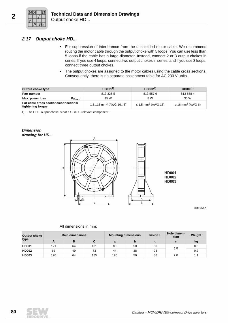
80
2 utput choke HD...echnical Data and Dimension Drawings
2.17 Output choke HD...
• For suppression of interference from the unshielded motor cable. We recommendrouting the motor cable through the output choke with 5 loops. You can use less than5 loops if the cable has a large diameter. Instead, connect 2 or 3 output chokes inseries. If you use 4 loops, connect two output chokes in series, and if you use 3 loops,connect three output chokes.
• The output chokes are assigned to the motor cables using the cable cross sections.Consequently, there is no separate assignment table for AC 230 V units.
Dimension drawing for HD...
All dimensions in mm:
Output choke type HD0011) HD0021) HD0031)
Part number 813 325 5 813 557 6 813 558 4
Max. power loss PVmax 15 W 8 W 30 W
For cable cross sections/connections/tightening torque 1.5...16 mm2 (AWG 16...6) ≤ 1.5 mm2 (AWG 16) ≥ 16 mm2 (AWG 6)
1) The HD... output choke is not a UL/cUL-relevant component.
58419AXX
d
abc
C
A
B
HD001HD002HD003
Output choke type
Main dimensions Mounting dimensions Inside ∅ Hole dimen-sion Weight
A B C a b d c kg
HD001 121 64 131 80 50 505.8
0.5
HD002 66 49 73 44 38 23 0.2
HD003 170 64 185 120 50 88 7.0 1.1
OT
Pi
fkVA
Hz
n
Catalog – MOVIDRIVE® compact Drive Inverters
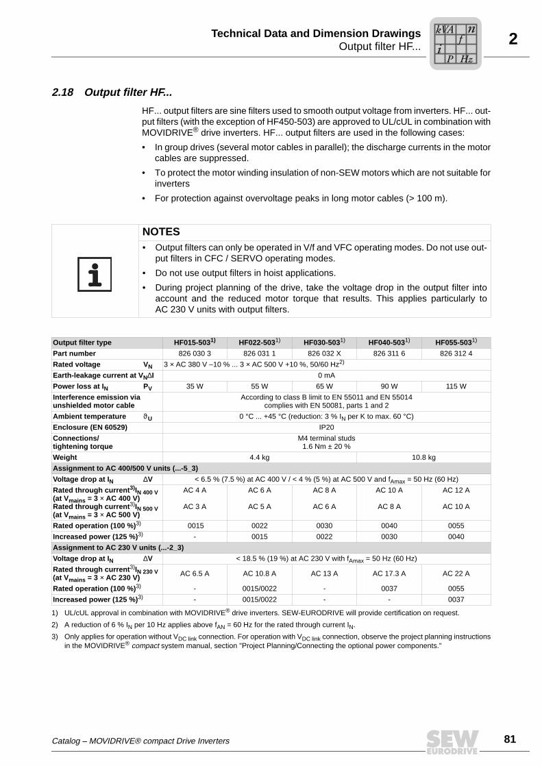
2Output filter HF...Technical Data and Dimension Drawings
2.18 Output filter HF...
HF... output filters are sine filters used to smooth output voltage from inverters. HF... out-put filters (with the exception of HF450-503) are approved to UL/cUL in combination withMOVIDRIVE® drive inverters. HF... output filters are used in the following cases:
• In group drives (several motor cables in parallel); the discharge currents in the motorcables are suppressed.
• To protect the motor winding insulation of non-SEW motors which are not suitable forinverters
• For protection against overvoltage peaks in long motor cables (> 100 m).
NOTES• Output filters can only be operated in V/f and VFC operating modes. Do not use out-
put filters in CFC / SERVO operating modes.
• Do not use output filters in hoist applications.
• During project planning of the drive, take the voltage drop in the output filter intoaccount and the reduced motor torque that results. This applies particularly toAC 230 V units with output filters.
Output filter type HF015-5031) HF022-5031) HF030-5031) HF040-5031) HF055-5031)
Part number 826 030 3 826 031 1 826 032 X 826 311 6 826 312 4
Rated voltage VN 3 × AC 380 V –10 % ... 3 × AC 500 V +10 %, 50/60 Hz2)
Earth-leakage current at VN∆I 0 mA
Power loss at IN PV 35 W 55 W 65 W 90 W 115 W
Interference emission via unshielded motor cable
According to class B limit to EN 55011 and EN 55014complies with EN 50081, parts 1 and 2
Ambient temperature ϑU 0 °C ... +45 °C (reduction: 3 % IN per K to max. 60 °C)
Enclosure (EN 60529) IP20
Connections/tightening torque
M4 terminal studs1.6 Nm ± 20 %
Weight 4.4 kg 10.8 kg
Assignment to AC 400/500 V units (...-5_3)
Voltage drop at IN ∆V < 6.5 % (7.5 %) at AC 400 V / < 4 % (5 %) at AC 500 V and fAmax = 50 Hz (60 Hz)
Rated through current3)IN 400 V(at Vmains = 3 × AC 400 V)Rated through current3)IN 500 V(at Vmains = 3 × AC 500 V)
AC 4 A
AC 3 A
AC 6 A
AC 5 A
AC 8 A
AC 6 A
AC 10 A
AC 8 A
AC 12 A
AC 10 A
Rated operation (100 %)3) 0015 0022 0030 0040 0055
Increased power (125 %)3) - 0015 0022 0030 0040
Assignment to AC 230 V units (...-2_3)
Voltage drop at IN ∆V < 18.5 % (19 %) at AC 230 V with fAmax = 50 Hz (60 Hz)
Rated through current3)IN 230 V(at Vmains = 3 × AC 230 V) AC 6.5 A AC 10.8 A AC 13 A AC 17.3 A AC 22 A
Rated operation (100 %)3) - 0015/0022 - 0037 0055
Increased power (125 %)3) - 0015/0022 - - 0037
1) UL/cUL approval in combination with MOVIDRIVE® drive inverters. SEW-EURODRIVE will provide certification on request.
2) A reduction of 6 % IN per 10 Hz applies above fAN = 60 Hz for the rated through current IN.
3) Only applies for operation without VDC link connection. For operation with VDC link connection, observe the project planning instructionsin the MOVIDRIVE® compact system manual, section "Project Planning/Connecting the optional power components."
Catalog – MOVIDRIVE® compact Drive Inverters
Pi
fkVA
Hz
n
81

82
2 utput filter HF...echnical Data and Dimension Drawings
Output filter type HF075-5031) HF023-4031) HF033-4031) HF047-4031) HF450-503
Part number 826 313 2 825 784 1 825 785 X 825 786 8 826 948 3
Rated voltage VN 3 × AC 380 V –10 % ... 3 × AC 500 V +10 %, 50/60 Hz2)
Earth-leakage current at VN∆I 0 mA
Power loss at IN PV 135 W 90 W 120 W 200 W 400 W
Interference emission via unshielded motor cable
According to class B limit to EN 55011 and EN 55014complies with EN 50081, parts 1 and 2
Ambient temperature ϑU 0 °C ... +45 °C (reduction: 3 % IN per K to max. 60 °C)
Enclosure (EN 60529) IP 20 IP20 IP 10
Connections/tightening torque
M4 terminal studs1.6 Nm ± 20 %
35 mm2 (AWG 2)3.2 Nm
Weight 10.8 kg 15.9 kg 16.5 kg 23 kg 32 kg
Assignment to AC 400/500 V units (...-5_3)
Voltage drop at IN ∆V < 6.5 % (7.5 %) at AC 400 V / < 4 % (5 %) at AC 500 V and fAmax = 50 Hz (60 Hz)
Rated through current3) IN 400 V(at Vmains = 3 × AC 400 V)Rated through current3) IN 500 V(at Vmains = 3 × AC 500 V)
AC 16 A
AC 13 A
AC 23 A
AC 19 A
AC 33 A
AC 26 A
AC 47 A
AC 38 A
AC 90 A
AC 72 A
Rated operation (100 %) 3) 0075 0110 0150/03004) 0220 0370/0450/05504)/07504)
Increased power (125 %) 3) 0055 0075 0110/02204) 0150 0300/0370/0450/05504)/07504)
Assignment to AC 230 V units (...-2_3)
Voltage drop at IN ∆V < 18.5 % (19 %) at AC 230 V with fAmax = 50 Hz (60 Hz)
Rated through current3) IN 230 V(at Vmains = 3 × AC 230 V) AC 29 A AC 42 A AC 56.5 A AC 82.6 A AC 156 A
Rated operation (100 %) 3) 0075 0110 0150/03004) 0220 0300
Increased power (125 %) 3) 0055 0075 0110/02204) 0150 0220/0300
1) UL/cUL approval in combination with MOVIDRIVE® drive inverters. SEW-EURODRIVE will provide certification on request.
2) A reduction of 6 % IN per 10 Hz applies above fAN = 60 Hz for the rated through current IN.
3) Only applies for operation without VDC link connection. For operation with VDC link connection, observe the project planning instructionsin the MOVIDRIVE® compact system manual, section "Project Planning/Connecting the optional power components."
4) Connect two HF...-... output filters in parallel for operation with these MOVIDRIVE® units.
OT
Pi
fkVA
Hz
n
Catalog – MOVIDRIVE® compact Drive Inverters

2Output filter HF...Technical Data and Dimension Drawings
Dimension drawings for output filter HF...-503, all dimensions in mm
HF008/015/022/030-503 HF040/055/075-503
58418AXXFigure 22: Dimension drawings for output filters HF008...075-503
Only the mounting position shown in the dimension drawing is permitted.
Output filter typeMain dimensions Mounting dimensions Hole dimension
Ventilation clearances1)
1) There is no need for clearance at the sides. You can line up the units next to one another.
A B C a b c Above Below
HF008/015/022/030-503 80 286 176 - 2657 100 100
HF040/055/075-503 135 296 216 70 283
HF450-503
58417AXXFigure 23: Dimension drawing for output filter HF450-503
Only the mounting position shown in the dimension diagram is permitted
Output filter typeMain dimensions Mounting dimensions Hole dimension Ventilation clearances
A B C a b c Above Below
HF450-503 465 385 240 436 220 8.5 100 100
b b
c ac
C CA A
B B
MOVIDRIVE®
MOVIDRIVE®
W1
W2
V1
V2
V5
U1
4 5 6 8
U2
MOVIDRIVE®
M~
1 11
a
b
B
c
A C
4 5 6 7 U V W
Catalog – MOVIDRIVE® compact Drive Inverters
Pi
fkVA
Hz
n
83

84
2 utput filter HF...echnical Data and Dimension Drawings
Dimension drawing for HF...-403 output filter, dimensions in mm
58996AXXFigure 24: Dimension drawing for HF...-403 output filter
TypeMain dimensions
Mounting dimensions Hole dimension
Ventilation clearancesStandard mounting position
Horizontal mount-ing position
A B C/C1 a b a1 a2 c Side Above Below
HF023-403145 284 365/390 268 60
210 334 6.5 30 each 150 150HF033-403
HF047-403 190 300 385/400 284 80
b
c
a
4567UVW
b1
a1
c
B
A C
C1
OT
Pi
fkVA
Hz
n
Catalog – MOVIDRIVE® compact Drive Inverters

2Prefabricated cablesTechnical Data and Dimension Drawings
2.19 Prefabricated cables
Overview SEW-EURODRIVE offers cable sets and prefabricated cables for straightforward andfault-free connection of various system components to MOVIDRIVE®. The cables areprefabricated in 1 m steps to the required length. It is necessary to differentiate betweenwhether the cables are intended for fixed routing or for cable carrier applications.
1. Cable sets for DC link connection MDR → MCF/MCV/MCS/MCH
2. Motor cables and extension cables for connecting CM motors to MCS and MCH
3. Motor cables for connecting DS motors to MCS
4. VR forced cooling fan cable and extension cable
5. Connection to X14/X15 of the MCV / MCS / MCH basic unit: Encoder cables andextension cables (Hiperface, incremental encoder), resolver cables and extensioncables in connector and terminal box design for motors for connecting the motorencoder to encoder input X15 of the MCV basic unit or to "X2: Encoder" of the 5 Vencoder supply type DWI11A.
1. Cable sets for DC link connection MDR → MCF/MCV/MCS/MCH
Description SEW-EURODRIVE strongly recommends using the cable sets listed in the table below.These cable sets offer the appropriate dielectric strength and are also color-coded. Col-or coding is necessary because cross-polarity and ground faults could cause irreparabledamage to the connected equipment.
The length of the cables restricts the DC link connection to the permitted length of 5 m.They can also be cut to length by the customer for connecting several units. The lugsfor connection to the regenerative power supply unit and an inverter are supplied withthe cable set. Use commercially available cable lugs to connect other inverters. In thiscase, connect inverters in star configuration to the regenerative power supply unit. Usea busbar subdistributor if the DC link terminals of the regenerative power supply unit arenot sufficient.
Installation type Only fixed routing is possible.
Cable set type DCP12A DCP13A DCP15A
Part number 814 567 9 814 250 5 814 251 3
For connecting MOVIDRIVE® 0015...0110 0150...0370 0450...0750
Catalog – MOVIDRIVE® compact Drive Inverters
Pi
fkVA
Hz
n
85

86
2 refabricated cablesechnical Data and Dimension Drawings
2. Motor cables for connecting CM motors to MCS and MCH and extension cables
Motor cables The cables are equipped with a connector for motor connection and conductor endsleeves for inverter connection.
Extension cables The cables are equipped with a connector and adapter for extending the CM motorcable.
Number of cores and line cross section Part number Installation type For motor
4×1.5 mm2 199 179 5
Fixed installation
CM..SM51
4×1.5 mm2 + 3×1.0 mm2 199 189 2 CM..BR SB51
4×2.5 mm2 199 181 7 CM..SM52
4×2.5 mm2 + 3×1.0 mm2 199 191 4 CM..BR SB52
4×4 mm2 199 183 3 CM..SM54
4×4 mm2 + 3×1.0 mm2 199 193 0 CM..BR SB54
4×6 mm2 199 185 X CM..SM56
4×6 mm2 + 3×1.5 mm2 199 195 7 CM..BR SB56
4×10 mm2 199 187 6 CM..SM59
4×10 mm2 + 3×1.5 mm2 199 197 3 CM..BR SB59
Number of cores and line cross section Part number Installation type For motor
4×1.5 mm2 1 333 114 0
Cable carrier installation
CM..SM51
4×1.5 mm2 + 3×1.0 mm2 1 333 116 7 CM..BR SB51
4×2.5 mm2 1 333 115 9 CM..SM52
4×2.5 mm2 + 3×1.0 mm2 1 333 117 5 CM..BR SB52
4×4 mm2 199 184 1 CM..SM54
4×4 mm2 + 3×1.0 mm2 199 194 9 CM..BR SB54
4×6 mm2 199 186 8 CM..SM56
4×6 mm2 + 3×1.5 mm2 199 196 5 CM..BR SB56
4×10 mm2 199 188 4 CM..SM59
4×10 mm2 + 3×1.5 mm2 199 198 1 CM..BR SB59
Number of cores and line cross section Part number Installation type For motor
4×1.5 mm2 199 549 9
Fixed installation
CM..SM51
4×1.5 mm2 + 3×1.0 mm2 199 199 X CM..BR SB51
4×2.5 mm2 199 551 0 CM..SM52
4×2.5 mm2 + 3×1.0 mm2 199 201 5 CM..BR SB52
4×4 mm2 199 553 7 CM..SM54
4×4 mm2 + 3×1.0 mm2 199 203 1 CM..BR SB54
4×6 mm2 199 555 3 CM..SM56
4×6 mm2 + 3×1.5 mm2 199 205 8 CM..BR SB56
4×10 mm2 199 557 X CM..SM59
4×10 mm2 + 3×1.5 mm2 199 207 4 CM..BR SB59
PT
Pi
fkVA
Hz
n
Catalog – MOVIDRIVE® compact Drive Inverters
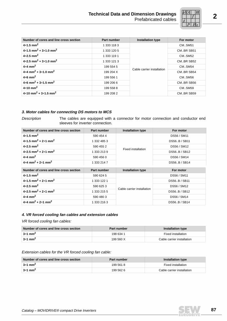
2Prefabricated cablesTechnical Data and Dimension Drawings
3. Motor cables for connecting DS motors to MCS
Description The cables are equipped with a connector for motor connection and conductor endsleeves for inverter connection.
4. VR forced cooling fan cables and extension cables
VR forced cooling fan cables:
Extension cables for the VR forced cooling fan cable:
Number of cores and line cross section Part number Installation type For motor
4×1.5 mm2 1 333 118 3
Cable carrier installation
CM..SM51
4×1.5 mm2 + 3×1.0 mm2 1 333 120 5 CM..BR SB51
4×2.5 mm2 1 333 119 1 CM..SM52
4×2.5 mm2 + 3×1.0 mm2 1 333 121 3 CM..BR SB52
4×4 mm2 199 554 5 CM..SM54
4×4 mm2 + 3×1.0 mm2 199 204 X CM..BR SB54
4×6 mm2 199 556 1 CM..SM56
4×6 mm2 + 3×1.5 mm2 199 206 6 CM..BR SB56
4×10 mm2 199 558 8 CM..SM59
4×10 mm2 + 3×1.5 mm2 199 208 2 CM..BR SB59
Number of cores and line cross section Part number Installation type For motor
4×1.5 mm2 590 454 4
Fixed installation
DS56 / SM11
4×1.5 mm2 + 2×1 mm2 1 332 485 3 DS56..B / SB11
4×2.5 mm2 590 455 2 DS56 / SM12
4×2.5 mm2 + 2×1 mm2 1 333 213 9 DS56..B / SB12
4×4 mm2 590 456 0 DS56 / SM14
4×4 mm2 + 2×1 mm2 1 333 214 7 DS56..B / SB14
Number of cores and line cross section Part number Installation type For motor
4×1.5 mm2 590 624 5
Cable carrier installation
DS56 / SM11
4×1.5 mm2 + 2×1 mm2 1 333 122 1 DS56..B / SB11
4×2.5 mm2 590 625 3 DS56 / SM12
4×2.5 mm2 + 2×1 mm2 1 333 215 5 DS56..B / SB12
4×4 mm2 590 480 3 DS56 / SM14
4×4 mm2 + 2×1 mm2 1 333 216 3 DS56..B / SB14
Number of cores and line cross section Part number Installation type
3×1 mm2 198 634 1 Fixed installation
3×1 mm2 199 560 X Cable carrier installation
Number of cores and line cross section Part number Installation type
3×1 mm2 199 561 8 Fixed installation
3×1 mm2 199 562 6 Cable carrier installation
Catalog – MOVIDRIVE® compact Drive Inverters
Pi
fkVA
Hz
n
87

88
2 refabricated cablesechnical Data and Dimension Drawings
5. Prefabricated cables for connection to X14/X15 on MCV / MCS / MCH basic units
The overviews on the following pages show all the connection options for X14/X15 onMCV / MCS / MCH basic units.
Meaning of the symbols
The connection cables are assigned a part number and a symbol. The symbols have thefollowing meaning:
Symbol Meaning
56047AXXConnection cable connector → connector for fixed installation
56051AXXExtension connection cable connector → connector for fixed installation
56048AXXConnection cable connector → connector for cable carrier installation
56052AXX
Extension connection cable connector → connector for cable carrier installation
56049AXXConnection cable connector → terminal box for fixed installation
56050AXXConnection cable connector → terminal box for cable carrier installation
56112AXX
Encoder connection via plug connector
56113AXX
Encoder connection via encoder terminal strip
56114AXX
Connection via plug connector on the motor side
56115AXX
Connection via terminal box on the motor side
PT
Pi
fkVA
Hz
n
Catalog – MOVIDRIVE® compact Drive Inverters

2Prefabricated cablesTechnical Data and Dimension Drawings
Connection options for X15 on the MCV basic unit
60069AXX
DT(E)/DV(E), eDT/eDV, CT/CVDR, DZ/DX
ES1S, ES2S, EV1S, EV2S, EH1SES1R, ES2R, EV1R, EV2R, EH1R
DT(E)/DV(E), eDT/eDVDR, DZ/DX
ES1T, ES2T, EV1T, EV2T, EH1T
X2 DWI11A→ TTL/5V
X15 MCV→ TTL Sin/Cos
1
5
6
9
5
1
9
6X2:
Enc
oder
X1:
MO
VID
RIV
E
DWI11A
DT(E)/DV(E), eDT/eDVDR, DZ/DX
ES1C, ES2C, EV1C EH1C, EV2C
X15 MCV→ X1 DWI11A
814 344 7
HTL
5
1
9
6
MCV
X15
198 829 8
198 828 X
198 829 8
198 828 X
198 932 4
198 931 6
NOTEFor individual wiring diagrams, refer to the section "Installation" in the MOVIDRIVE®
compact operating instructions.
Catalog – MOVIDRIVE® compact Drive Inverters
Pi
fkVA
Hz
n
89

90
2 refabricated cablesechnical Data and Dimension Drawings
• Cable to connect sin/cos encoders ES1S, ES2S, EV1S, EV2S, EH1S, ES1R, ES2R,EV1R, EV2R, EH1R with terminal box connection on the motor side to CT, CV,DT(E), DV(E), eDT, eDV, DR, DZ and DX motors.
• Cable to connect single-ended HTL encoders ES1C, ES2C, EV1C, EV2C, EH1Cwith terminal box connection on the motor side to DT(E), DV(E), eDT, eDV, DR, DZand DX motors.
56132AXX
Type Installation Part number
MCV X15 → DT(E)/DV(E)/eDT/eDV/CT/CV/DR/DZ/DX motors with sin/cos encoders ES1S, ES2S, EV1S, EV2S, EH1S, ES1R, ES2R, EV1R, EV2R, EH1R
56049AXX198 829 8
56050AXX
198 828 X
56132AXX
Type Installation Part number
HTL encoders ES1C, ES2C, EV1C, EV2C, EH1C → DT(E)/DV(E)/eDT/eDV/DR/DZ/DX motors
56049AXX198 932 4
56050AXX
198 931 6
PT
Pi
fkVA
Hz
n
Catalog – MOVIDRIVE® compact Drive Inverters

2Prefabricated cablesTechnical Data and Dimension Drawings
• Cable to connect DC 5 V TTL sensors ES1T, ES2T, EV1T, EV2T, EH1T with terminalbox connection on the motor side (DT(E), DV(E), eDT, eDV, DR, DZ or DX motors)to DC 5 V encoder power supply type DWI11A.
• Cable to connect the DC 5 V encoder power supply type DWI11A via plug connector.
56132AXX
Type Installation Part number
DC 5 V TTL sensors ES1T, ES2T, EV1T, EV2T, EH1T→ DWI11A X2
56049AXX198 829 8
56050AXX198 828 X
56109AXX
Type Installation Part number
MCV X15 → DWI11A X156047AXX
814 344 7
Catalog – MOVIDRIVE® compact Drive Inverters
Pi
fkVA
Hz
n
91
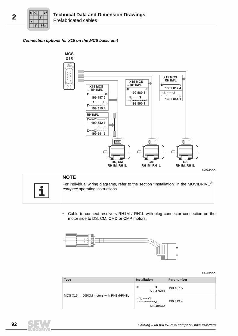
92
2 refabricated cablesechnical Data and Dimension Drawings
Connection options for X15 on the MCS basic unit
• Cable to connect resolvers RH1M / RH1L with plug connector connection on themotor side to DS, CM, CMD or CMP motors.
60072AXX
DS, CMRH1M, RH1L
CMRH1M, RH1L
DSRH1M, RH1L
X15 MCS→ RH1M/L
199 487 5
199 319 4
RH1M/L
199 542 1
199 541 3
X15 MCS→RH1M/L
199 589 8
199 590 1
X15 MCS→ RH1M/L
1332 817 4
1332 844 1
6
5
1
9
MCS
X15
NOTEFor individual wiring diagrams, refer to the section "Installation" in the MOVIDRIVE®
compact operating instructions.
56138AXX
Type Installation Part number
MCS X15 → DS/CM motors with RH1M/RH1L56047AXX
199 487 5
56048AXX199 319 4
PT
Pi
fkVA
Hz
n
Catalog – MOVIDRIVE® compact Drive Inverters

2Prefabricated cablesTechnical Data and Dimension Drawings
• Extension cable to connect RH1M / RH1L resolvers with plug connector connectionon the motor side to DS or CM motors.
• Cable to connect resolvers RH1M / RH1L with terminal box connection on the motorside to CM and DS motors.
56139AXX
Type Installation Part number
MCS X15 → DS/CM motors with RH1M/RH1L56051AXX
199 542 1
56052AXX
199 541 3
56142AXX
Type Installation Part number
MCS X15 → CM motors with RH1M/RH1L56049AXX
199 589 8
56050AXX199 590 1
MCS X15 → DS motors with RH1M/RH1L56049AXX
1332 817 4
56050AXX1332 844 1
Catalog – MOVIDRIVE® compact Drive Inverters
Pi
fkVA
Hz
n
93

94
2 refabricated cablesechnical Data and Dimension Drawings
Connection options for X15 on the MCH basic unit
• Cable to connect HIPERFACE® encoders AK0H, AS1H, AS3H, AS4H, EK0H, ES1H,ES3H, ES4H, EV1H, AV1H with plug connector connection on the motor side to DS,CM, DT, DV, DT(E), DV(E), CT, CV, DZ or DX motors.
60070AXX
9
8
1
15
DS, CM, DT(E)/DV(E), CT/CV, DZ/DXAS0H, AS1H, AS3H, AS4HES0H, ES1H, ES3H, ES4H
AV1H CMAS1H, ES1H
X15 MCH→ Hiperface®
Hiperface®
199 539 1
199 540 5
X15 MCH → Hiperface®
MCHX15
199 488 3
199 320 8
199 591 X
199 592 8
NOTEFor individual wiring diagrams, refer to the section "Installation" in the MOVIDRIVE®
compact operating instructions.
56135AXX
Type Installation Part number
MCH X15 → DS/CM/DT/DV/DT(E)/DV(E)/CT/CV/DZ/DX motors with AK0H, AS1H, AS3H, AS4H, EK0H, ES1H, ES3H, ES4H, EV1H, AV1H
56047AXX199 488 3
56048AXX199 320 8
PT
Pi
fkVA
Hz
n
Catalog – MOVIDRIVE® compact Drive Inverters

2Prefabricated cablesTechnical Data and Dimension Drawings
• Extension cable to connect HIPERFACE® encoders AK0H, AS1H, AS3H, AS4H,EK0H, ES1H, ES3H, ES4H, EV1H, AV1H with plug connector connection on themotor side to DS, CM, DT, DV, DT(E), DV(E), CT, CV, DZ or DX motors.
• Cable to connect HIPERFACE® encoders AS1H, ES1H with terminal box connectionon the motor side to CM motors.
56136AXX
Type Installation Part number
MCH X15 → DS/CM/DT/DV/DT(E)/DV(E)/CT/CV/DZ/DX motors with AK0H, AS1H, AS3H, AS4H, EK0H, ES1H, ES3H, ES4H, EV1H, AV1H
56051AXX199 539 1
56052AXX
199 540 5
56137AXX
Type Installation Part number
MCH X15 → CM motors with AS1H, ES1H56049AXX
199 591 X
56050AXX
199 592 8
Catalog – MOVIDRIVE® compact Drive Inverters
Pi
fkVA
Hz
n
95
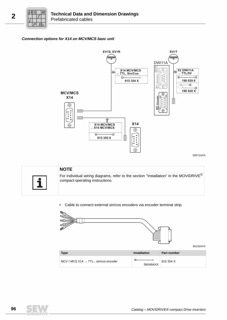
96
2 refabricated cablesechnical Data and Dimension Drawings
Connection options for X14 on MCV/MCS basc unit
• Cable to connect external sin/cos encoders via encoder terminal strip.
60071AXX
1
5
6
9
5
1
9
6
EV1S, EV1R EV1T
X2
: E
nc
od
er
X1
: M
OV
IDR
IVE
DWI11A
X14 MCV/MCS→ TTL, Sin/Cos
815 354 X
X14 MCV/MCS→ X14 MCV/MCS
815 355 8
X2 DWI11A→ TTL/5V
198 829 8
198 828 X
5
1
9
6
5
1
9
6
MCV/MCS
X14
X14
NOTEFor individual wiring diagrams, refer to the section "Installation" in the MOVIDRIVE®
compact operating instructions.
56132AXX
Type Installation Part number
MCV / MCS X14 → TTL-, sin/cos encoder56049AXX
815 354 X
PT
Pi
fkVA
Hz
n
Catalog – MOVIDRIVE® compact Drive Inverters

2Prefabricated cablesTechnical Data and Dimension Drawings
• Cable to connect an external DC 5 V TTL sensor to the DC 5 V encoder power supplytype DWI11A via encoder terminal strip.
• Cable to connect a master/slave connection.
56132AXX
Type Installation Part number
DC 5 V TTL sensor → DWI11A X256049AXX
198 829 8
56050AXX198 828 X
56109AXX
Type Installation Part number
MCV/MCS X14 → MCV/MCS X1456047AXX
815 355 8
Catalog – MOVIDRIVE® compact Drive Inverters
Pi
fkVA
Hz
n
97

98
3 otor selection for asynchronous AC motors (VFC)otor Selection
3 Motor Selection3.1 Motor selection for asynchronous AC motors (VFC)
Basic recommen-dations
• Only use motors with at least thermal class F.
• Use TF thermistors or TH winding thermostats. TH should be preferred for groupdrives on one inverter. The series connection of the TH contacts (normally closed) isnot subject to limitation when both monitoring functions are used.
• For group drives, we recommend that the motors should not differ from one anotherby more than 3 motor types.
• Use 4-pole motors if possible. This recommendation applies particularly to gear-motors operated with a high oil filling level due to their vertical mounting position.
• Generally speaking, the motor can be operated at its listed power without forcedcooling if the operating conditions differ from S1 operation, e.g. positioning drive with1:20 speed range in S3 operation.
• Do not select a motor that is too big, particularly for delta connection. Otherwise, theinverter may trigger a short circuit fault.
• A MOVIDRIVE® compact MCV4_A or MCH4_A drive inverter is required for speedcontrol. In this case, the motor must be equipped with an incremental encoder, pref-erably with 1024 increments/revolution or with a Hiperface encoder.
Voltage/fre-quency charac-teristic curve
The VFC operating mode runs the asynchronous motor on a load-dependent volt-age/frequency curve. The continuous calculation of the motor model enables the fullmotor torque to be utilized right down to the lowest speeds. This characteristic curve isset by entering the rated motor voltage and the rated motor frequency in the startupfunction. The setting determines the speed-dependent torque and power characteristicsof the asynchronous motor.
The following figure shows an example of the voltage/frequency characteristic curve ofan asynchronous AC motor 230/400 V, 50 Hz.
1 Star connection; 400 V, 50 Hz
2 Delta connection: 230 V, 50 Hz
3 Delta connection: 400 V, 87 Hz
The inverter output voltage Vout is limited by the connected supply voltage. The "ratedsupply voltage" input value in the startup function limits the effective value of the maxi-mum output voltage. This restriction is used whenever the connected motor has a lowerrated voltage than the power supply of the inverter. Enter the maximum permitted motorvoltage. Furthermore, make sure that the "rated supply voltage" input value is less thanor equal to the supply voltage of the inverter.
01650BENFigure 25: Voltage/frequency characteristics of the asynchronous motor
0
230
400
0 f [Hz]50 87
1 3
2
Voutp [V]
MM
Catalog – MOVIDRIVE® compact Drive Inverters

3Motor selection for asynchronous AC motors (VFC)Motor Selection
Speed/torque characteristic curve
The field weakening range starts when the set maximum output voltage of the inverteris reached. Consequently, the speed range of the motor is divided into two ranges:
• Basic speed range → constant torque with increasing power.
• Field weakening range → constant power with an inversely proportionate decreasein torque.
When determining the maximum speed in the field weakening range, note that the ratedtorque MN (in relation to the rated speed, e.g. nN = 1,500 1/min) falls in inverse propor-tion and the breakdown torque MK is reduced in an inverse quadratic relationship. TheMK/MN ratio is a motor-specific parameter. The MOVIDRIVE® breakdown protection lim-its the speed when the maximum possible torque is reached.
With gearmotors, the maximum motor speed depends on the size and mounting positionof the gear unit. The speed should not exceed 3,000 1/min due to the resulting noise andoil churning losses.
Dynamic applica-tions (Pinverter greater than Pmotor)
• The startup function sets the current limit of the inverter (P303/P313) to 150 % of therated motor current. The value of the current limit is based on the rated inverter cur-rent. 150% of the rated motor current is, therefore, less than 150 % of the rated in-verter current (value of P303 P313). For dynamic applications, this parameter mustbe set manually to a higher value.
• The startup function sets the slip compensation parameter (P324/P334) to the ratedslip of the motor. In the case of VFC-n-CONTROL, the internal slip limiting functionallows the slip to reach max. 150 % of this setting. Consequently, the motor developsat most 150 % of the rated motor torque. For higher torque ratings, the slip compen-sation parameter (P324) must be increased accordingly.
01729BENFigure 26: Quadratically falling breakdown torque
0 1500 1800 2100 2400 2700 3000 3300 36000
MN
MMN
M = 1.8 MK N
M = 2.2 MK N
M = 2.5 MK N
M = 2.8 MK N
M = 3.0 MK N
0.5
1.0
1.5
2.0
2.5
3.0
Armature range Field weakening range
n / rpm
NOTESet parameter P324 "Slip compensation" to max. 130 % of the rated slip of the motorfor stable operation.
Catalog – MOVIDRIVE® compact Drive Inverters
99
100
3 otor selection for asynchronous AC motors (VFC)otor Selection
Combinations with Pinverter greater than 4 × Pmotor
Due to the great difference between the rated inverter and rated motor currents, thiscombination cannot be started without additional measures:
• Perform project planning for connecting the motor in a delta connection. This increas-es the motor current by a factor of √3 and lowers the unfavorable ratio.
• If this measure does not suffice, start up the motor in VFC & GROUP operatingmode. In this operating mode, the inverter operates without slip compensation andsimulates a constant-voltage/ constant-frequency system (system with a constant V/fratio).
MM
Catalog – MOVIDRIVE® compact Drive Inverters

3Motor selection for asynchronous AC motors (VFC)Motor Selection
Motor selection in connection type delta/star (AC 230/400 V / 50 Hz)
Motors for AC 380 V / 60 Hz can also be allocated on the basis of this selection table.
Pmax [kW] for operation on MOVIDRIVE® compact MCF/MCV/MCH 4_A...-5_3 (AC 400/500 V units)
Connection / AC 400 V1)
1) Also applies to motors with rated voltage 460 V or 500 V and for motors 400/690 V with ∆ connection.
∆ / AC 230 V2)
2) Also applies to motors with 266 V or 290 V rated voltage.
Cooling Own Forced Own Forced
fmin - fmax [Hz]10 - 506 - 60
5 - 70 / 5.5 - 80≤ 2.5 - 50 / ≤ 3 - 603)
3) The following applies to MCF, MCV and MCH without speed control: fmin = 0.5 Hz
9 - 87 ≤ 2.5 - 873)
nmin - nmax [1/min]300 - 1500180 - 1800
150 - 2100 / 165 - 2400≤ 75 - 1500 / ≤ 90 - 1800 270 -
2610 ≤ 75 - 2610
Setting range1:5
1:101:15
≥ 1:20 1:10 ≥ 1:20
Motor type Rated power Pn[kW]
P = Preduced P = Pn P = Pincreased4)
4) Pincreased means that the motor is operated at the power of the next larger motor (one frame size), rather than with √3-fold power.
[kW] MCF/MCV/MCH5)
4_A...-5_3
5) The units listed here permit intermittent loads of up to 1.5 times the rated load in the specific application. With variable torque load andconstant load without overload, each inverter can also be operated with increased continuous output power (→ Sec. Technical Data).The continuous output current of 125% of the rated unit current is only available at fPWM = 4 kHz.
[kW] MCF/MCV/MCH5)
4_A...-5_3 [kW] MCF/MCV/MCH5)
4_A...-5_3
DT71D4 0.37 0.25
0015
0.37
0015
0.55
0015DT80K4 0.55 0.37 0.55 0.75
DT80N4 0.75 0.55 0.75 1.1
DT90S4 1.1 0.75 1.1 1.5
DT90L4 1.5 1.1 1.5 2.2 0022
DV100M4 2.2 1.5 2.2 0022 3.0 0030
DV100L4 3.0 2.2 0022 3.0 0030 4.0 0040
DV112M4 4.0 3.0 0030 4.0 0040 5.5 0055
DV132S4 5.5 4.0 0040 5.5 0055 7.5 0075
DV132M4 7.5 5.5 0055 7.5 0075 9.20110
DV132ML4 9.2 7.5 0075 9.20110
11
DV160M4 11 9.20110
11 15 0150
DV160L4 15 11 15 0150 18.5 0220
DV180M4 18.5 15 0150 18.50220
22 0300
DV180L4 22 18.50220
22 300370
DV200L4 30 22 30 0300 37
DV225S4 37 30 0300 37 0370 45 0450
DV225M4 45 37 0370 45 0450 55 0550
DV250M4 55 45 0450 55 0550 75 0750
DV280S4 75 55 0550 75 0750-
DV280M4 90 75 0750 -
Catalog – MOVIDRIVE® compact Drive Inverters
101
102
3 otor selection for asynchronous AC motors (VFC)otor Selection
Examples for motor selection for delta/star AC 230/400 V
Trolley drive Constant load with overload (acceleration) and low load during travel:
• Ptravel = 1.3 kW
• Pmax = 13 kW
• nmin = 270 1/min, setting range 1:10
• nmax = 2610 1/min
In inverter mode with adapted power (P = Pn), the motor can output 150 % of its listedpower during the acceleration phase. The following applies:
PMot = Pmax : 1.5 = 13 kW : 1.5 = 8.67 kW
A DV132M4 motor with delta connection (Pn = 9.2 kW) is selected.
The selection table (→ page 101) allocates a MOVIDRIVE® compact MCF60A0110 (P =Pn).
Hoist drive High constant load with short-term overload (acceleration):
• Pmax = 26 kW
• Pconst. = 20 kW
• Setting range 1:15, low speed only for positioning
• Brake applied when the drive is at a standstill
• Load type S3 (40 % cdf)
The inverter can yield 150 % of its rated current during acceleration. Consequently, aMOVIDRIVE® compact MCF60A0220 is selected.
In view of the load type (S3, 40 % cdf), the selection table allocates motor type DV180L4(Pn = 22 kW) in a star connection.
For further information → section "Project planning" in the MOVIDRIVE® compactsystem manual.
Fan/pump Variable torque load with the following power values:
• Pmax = 4.8 kW
• nmax = 1,400 1/min, continuous duty with nmax
The motor can be operated at its listed power (P = Pn) even without forced cooling dueto the quadratically falling torque. Therefore, the motor type DV132S4 in star connection(Pn = 5.5 kW) is sufficient.
The selection table allocates a MOVIDRIVE® compact MCF60A0055 (P = Pn).However, as there is a variable torque load without overload, the inverter can be oper-ated with increased output power. Consequently, a MOVIDRIVE® compactMCF60A0040 is sufficient.
MM
Catalog – MOVIDRIVE® compact Drive Inverters

3Motor selection for asynchronous AC motors (VFC)Motor Selection
Motor selection in connection type double-star/star (AC 230/460 V / 60 Hz)
Pmax [kW] for operation on MOVIDRIVE® compact MCF/MCV/MCH 4_A...-5_3 (AC 400/500 V units)
Connection / AC 460 V / AC 230 V
Cooling Own Own Forced Own Forced
fmin - fmax [Hz] 6 - 90 10 - 60 0 - 601)
1) The following applies to MCF, MCV and MCH without speed control: fmin = 0.5 Hz
10 - 120 0 - 1201)
nmin - nmax [1/min] 180 - 2700 200 - 1800 0 - 1800 200 - 3600 0 - 3600
Setting range 1:15 1:6 ≥ 1:15 1:12 ≥ 1:20
Motor type Rated power Pn[kW]
P = Preduced P = Pn P = Pincreased2)
2) Pincreased means that the motor is operated at the power of the next larger motor (one frame size), rather than with √3-fold power.
[kW] MCF/MCV/MCH3)
4_A...-5_3
3) The units listed here permit intermittent loads of up to 1.5 times the rated load in the specific application. With variable torque load andconstant load without overload, each inverter can also be operated with increased continuous output power (→ Sec. Technical Data).The continuous output current of 125 % of the rated unit current is only available at fPWM = 4 kHz.
[kW] MCF/MCV/MCH3)
4_A...-5_3 [kW] MCF/MCV/MCH3)
4_A...-5_3
DT71D4 0.37 0.25
0015
0.37
0015
0.75
0015DT80K4 0.55 0.37 0.55 1.1
DT80N4 0.75 0.55 0.75 1.5
DT90S4 1.1 0.75 1.1 2.2 0022
DT90L4 1.5 1.1 1.5 3.0 0030
DV100M4 2.2 1.5 2.2 0022 4.0 0040
DV100L4 3.7 2.2 0022 3.0 0030 5.5 0055
DV112M4 4.0 3.0 0030 4.0 0040 7.5 0075
DV132S4 5.5 4.0 0040 5.5 0055 9.20110
DV132M4 7.5 5.5 0055 7.5 0075 11
DV132ML4 9.2 7.5 0075 9.20110
15 0150
DV160M4 11 9.20110
11 18.50220
DV160L4 15 11 15 0150 22
DV180M4 18.5 15 0150 18.50220
30 0300
DV180L4 22 18.50220
22 37 0370
DV200L4 30 22 30 0300 45 0450
DV225S4 37 30 0300 37 0370 55 0550
DV225M4 45 37 0370 45 0450 75 0750
DV250M4 55 45 0450 55 0550
-DV280S4 75 55 0550 75 0750
DV280M4 90 75 0750 -
Catalog – MOVIDRIVE® compact Drive Inverters
103
104
3 otor selection for asynchronous AC motors (VFC)otor Selection
Motor selection for delta connection (AC 230 V / 50 Hz)
Pmax [kW] for operation on MOVIDRIVE® compact MCF/MCV/MCH 4_A...-2_3 (AC 230 V units)
Connection ∆ / AC 230 V
Cooling Own Forced
fmin - fmax [Hz]10 - 506 - 60
5 - 70 / 5.5 - 80≤ 2.5 - 50 / ≤ 3 - 601)
1) The following applies to MCF, MCV and MCH without speed control: fmin = 0.5 Hz
nmin - nmax [1/min]300 - 1500180 - 1800
150 - 2100 / 165 - 2400≤ 75 - 1500 / ≤ 90 - 1800
Setting range1:5
1:101:15
≥ 1:20
Motor type2)
2) In load type S3 (40 % cdf), the motor can be operated at its listed power (P = Pn) without forced cooling. Example: Pstat = 2 kW, Pdyn= 2.5 kW → selected motor DV100M4 (Pn = 2.2 kW).
Rated power Pn[kW]
P = Preduced P = Pn
[kW] MCF/MCV/MCH3)
4_A...-2_3
3) The units listed here permit intermittent loads of up to 1.5 times the rated load in the specific application. With variable torque load andconstant load without overload, each inverter can also be operated with increased continuous output power (→ Sec. Technical Data).The continuous output current of 125 % of the rated unit current is only available at fPWM = 4 kHz.
[kW] MCF/MCV/MCH3)
4_A...-2_3
DT71D4 0.37 0.25
0015
0.37
0015
DT80K4 0.55 0.37 0.55
DT80N4 0.75 0.55 0.75
DT90S4 1.1 0.75 1.1
DT90L4 1.5 1.1 1.5
DV100M4 2.2 1.5 2.2 0022
DV100L4 3.0 2.2 0022 3.0 0030
DV112M4 4.0 3.0 0030 4.0 0040
DV132S4 5.5 4.0 0040 5.5 0055
DV132M4 7.5 5.5 0055 7.5 0075
DV132ML4 9.2 7.5 0075 9.20110
DV160M4 11 9.20110
11
DV160L4 15 11 15 0150
DV180M4 18.5 15 0150 18.5 0220
DV180L4 22 18.50220
220300
DV200L4 30 22 30
DV225S4 37 30 0300 -
MM
Catalog – MOVIDRIVE® compact Drive Inverters

3Motor selection for asynchronous AC motors (VFC)Motor Selection
Motor selection for connection type double-star (AC 230 V / 60 Hz)
Pmax [kW] for operation on MOVIDRIVE® compact MCF/MCV/MCH 4_A...-2_3 (AC 230 V units)
Connection / AC 230 V
Cooling Own Own Forced
fmin - fmax [Hz] 6 - 90 10 - 60 0 - 601)
1) The following applies to MCF, MCV and MCH without speed control: fmin = 0.5 Hz
nmin - nmax [1/min] 180 - 2700 200 - 1800 0 - 1800
Setting range 1:15 1:6 ≥ 1:15
Motor type Rated power Pn[kW]
P = Preduced P = Pn
[kW] MCF/MCV/MCH2)
4_A...-2_3
2) The units listed here permit intermittent loads of up to 1.5 times the rated load in the specific application. With variable torque load andconstant load without overload, each inverter can also be operated with increased continuous output power (→ Sec. Technical Data).The continuous output current of 125% of the rated unit current is only available at fPWM = 4 kHz.
[kW] MCF/MCV/MCH3)
4_A...-2_3
DT71D4 0.37 0.25
0015
0.37
0015
DT80K4 0.55 0.37 0.55
DT80N4 0.75 0.55 0.75
DT90S4 1.1 0.75 1.1
DT90L4 1.5 1.1 1.5
DV100M4 2.2 1.5 2.2 0022
DV100L4 3.7 2.2 0022 3.0 0030
DV112M4 4.0 3.0 0030 4.0 0040
DV132S4 5.5 4.0 0040 5.5 0055
DV132M4 7.5 5.5 0055 7.5 0075
DV132ML4 9.2 7.5 0075 9.20110
DV160M4 11 9.20110
11
DV160L4 15 11 15 0150
DV180M4 18.5 15 0150 18.5 0300
DV180L4 22 18.50220
220370
DV200L4 30 22 30
DV225S4 37 30 0300 -
Catalog – MOVIDRIVE® compact Drive Inverters
105
106
3 otor selection for asynchronous servomotors (CFC)otor Selection
3.2 Motor selection for asynchronous servomotors (CFC)
Basic recommen-dations
Observe the following recommendations for selecting the motor:
• Only use motors with at least thermal class F.
• Use TF thermistors or TH winding thermostats.
Motor characteristics
Drives in CFC operating modes are characterized by their ability to control torque direct-ly and quickly. This means they achieve a highly dynamic overload capacity (up to 3 ×MN) and a very high speed and control range (up to 1:5000). Stable speed and position-ing accuracy meet the high requirements of servo technology. These characteristics aremade possible through field-oriented control. The current components for magnetization(Id) and torque generation (Iq) are controlled separately. A prerequisite for the CFC op-erating modes is that the motor must always be equipped with an encoder.
The inverter needs to know exact data about the connected motor to calculate the motormodel. This data is made available by the MOVITOOLS® operating software with thestartup function. CFC operating modes are only possible with 4-pole SEW-motors(CT/CV or DT/DV), not with other SEW motors or non-SEW motors. For 4-pole SEWmotors, the motor data required for the CFC operating modes is stored in MOVIDRIVE®.
Typical speed/torque char-acteristic curve
MN is determined by the motor. Mmax and ntrans depend on the motor/inverter combina-tion. Refer to the motor selection tables for the CFC mode for the values of ntrans, MNand Mmax.
NOTEThe torque limit (M limit) is set automatically by the startup function of theMOVITOOLS® operating software. Do not increase this automatically set value!
SEW-EURODRIVE recommends always using the latest version of MOVITOOLS® forstartup. The latest MOVITOOLS® version can be downloaded from our homepage(www.sew-eurodrive.com).
01651BENFigure 27: Speed/torque characteristic curve in CFC operating mode
1 With self-cooling
2 With forced cooling
3 Maximum torque
0
Mmax
0
2
1
3
n
M
ntrans
MN
1.4 n× trans
MM
Catalog – MOVIDRIVE® compact Drive Inverters

3Motor selection for asynchronous servomotors (CFC)Motor Selection
Magnetizing current
Dynamic drives that have to accelerate without a delay are also energized at standstillwithout load. The magnetizing current Id flows at standstill. The inverter must be able tosupply this current constantly in applications in which the output stage is permanentlyenabled, for example in CFC & M-CONTROL mode. In particular in the case of large mo-tors with a slip frequency ≤ 2 Hz, you have to refer to the diagrams in the section "Over-load capacity of the inverters" to check whether the inverter can supply the current. Alsocheck whether the thermal characteristics of the motor are suitable (forced cooling fan)for this. For the magnetizing current Id, refer to the motor tables (CT/CV → page 110,DT/DV → page 115).
CFC mode with speed control
There is no need to differentiate between the load types quadratic, dynamic and staticwhen performing project planning for the CFC operating mode. Project planning for anasynchronous motor in CFC mode is carried out in accordance with the following re-quirements:
1. Effective torque requirement at average application speed.
Meff < MN_Mot
The operating point must lie below the characteristic curve for the continuous torque(Figure 27, curve 2). If this operating point lies below the characteristic curve forforced cooling (Figure 27, curve 1), then no forced cooling is required.
2. Maximum torque needed across the speed curve.
Mmax < Mdyn_Mot
This operating point must lie below the characteristic curve for the maximum torqueof the motor/MOVIDRIVE® combination (Figure 27, curve 3).
3. Maximum speed
Do not configure the maximum speed of the motor higher than 1.4 times the transi-tion speed. The maximum torque available will then still be approximately 110 % ofthe continuous rated torque of the motor; also, the input speed for the gear unit con-nected to the motor output will still be less than 3,000 1/min with delta connection.
nmax < 1.4 × ntrans < 3000 1/min
Cooling the motor
Self-cooling of asynchronous motors is based on the integrated fan, which means self-cooling depends on the speed. The integrated fan does not provide cooling for the motorat low speeds and standstill. Forced cooling may be necessary in case of a high staticload or a high effective torque.
Catalog – MOVIDRIVE® compact Drive Inverters
107
108
3 otor selection for asynchronous servomotors (CFC)otor Selection
CFC operation with torque con-trol (CFC & M-CONTROL)
This operating mode permits direct torque control of the asynchronous motor in the ba-sic speed range (n ≤ ntrans). The setpoint sources of the speed-controlled CFC modecan also be used for torque control. All speed setpoint sources (except for bus setpoints)are interpreted as current setpoint sources. Assign "Current" to a process data word forfieldbus control. The settings for evaluating the analog input (→ P11_, parameter de-scription) also remain in effect. The fixed setpoints (P16_, P17_) can be entered in theunits [1/min] or [%IN_inverter] as required (→ MOVITOOLS®).
The following relationship exists between the units:
3000 1/min = 150 % rated inverter current
The torque on the output shaft of the motor can be calculated for the basic speed range(n ≤ ntrans) using the following formulae:
Specification of a setpoint for the motor torque in %IN_inverter:
Specification of a setpoint for the motor torque in 1/min:
In addition to the current Iq for creating the torque, the inverter also needs to supply themagnetizing current Id. The actual inverter output current Itot can be calculated using thefollowing formulae:
Specification of a setpoint for the motor torque in %IN_inverter:
Specification of a setpoint for the motor torque in 1/min:
04972AEN
04973AEN
IN_inverter = Rated output current of the inverter
kT = Torque constant = Mn / Iq_n
Mn and Iq_n are motor-specific values. For the values of the torque constants kT and the motor-specific values Mn and Iq_n, refer to the motor tables (DT/DV → page 115, CT/CV → page 109).
04974AEN
04975AEN
Iq_n = Nominal value of the torque-generating current according to the motor table
Id_n = Nominal value of the magnetizing current according to the motor table
M = kT x I
n_inverter x Setpoint
M = kT x 1.5 x I
n_inverter x
3000 rpm
Setpoint
I Setpo I Itot n inverter d N= × +int _ _d i2 2
I Setpo Irpm
Itot n inverter d N= × × ×FHG
IKJ
+int . _ _1 51
3000
22
MM
Catalog – MOVIDRIVE® compact Drive Inverters

3Motor selection for asynchronous servomotors (CFC)Motor Selection
Asynchronous servomotors CT/CV
SEW-EURODRIVE offers CT/CV asynchronous servomotors specifically for operationwith MOVIDRIVE® in the CFC operating modes. These motors have the following char-acteristics:
High power yield The optimum winding of CT/CV motors permits a high power yield.
Division into speed classes
CT/CV motors are available in four speed classes. This division ensures optimum utili-zation of torque and speed.
Sin/cos encoder as standard
CT/CV motors are equipped as standard with a high-resolution sin/cos encoder (ES1S,ES2S, EV1S).
TF or TH motor protection as standard
The winding temperature of the three motor phases is monitored using thermistors (TF).The thermistor can be connected to the TF/TH input of MOVIDRIVE®. The temperatureis then monitored by MOVIDRIVE®; no additional monitoring unit is required.
Bimetallic switches (TH) can also be used instead of thermistors. The bimetallicswitches are also connected to the TF/TH input.
Thermal classifica-tion F as standard
CT/CV motors are designed with thermal classification F materials.
Reinforced pinion shaft ends
CT/CV motors can generate up to three times their rated motor torque in dynamic oper-ation. For this reason, these motors are equipped with reinforced pinion shaft ends fordirect mounting to gear units to enable them to transmit the high torque levels reliably.
Either DT/DV/ motors or CT/CV motors can be used in CFC mode. SEW-EURODRIVErecommends using CT/CV motors to achieve optimum benefit from the CFC mode.
Advantage Disadvantage
CFC mode with DT/DV motorMotor selection → page 119 Standard motor version
Lower transition speed than the CT/CV motor.
The power yield of the motor is less than the rated motor power.
In terms of the power yield, the mass inertia is greater than that of
the CT/CV motors.
The maximum torque is limited for some of the inverter/motor combi-nations due to mechanical rigidity.
CFC mode with CT/CV motorMotor selection → page 111
Higher transition speed than DT/DV motor.
No IEC standard motorUsually with a power yield one
motor type higher.
Based on the power yield of a lower mass moment of inertia.
Higher current demand due to higher power yield; therefore a
larger inverter has to be assigned.
Motor is designed for dynamic operation.
Catalog – MOVIDRIVE® compact Drive Inverters
109
110
3 otor selection for asynchronous servomotors (CFC)otor Selection
CT/CV motor tablenN Motor MN IN Iq_n Id_n kT UN JMot JBMot
[1/min] [Nm] [A] [A] [A] [Nm/A] [V] [10-4 kgm2]
1200
CT71D4 3 1.4 1.21 0.69 2.48 360 4.6 5.5
CT80N4 5 2.1 1.65 1.30 3.0 350 8.7 9.6
CT90L4 10 3.65 3.13 1.89 3.2 345 34 39.5
CV100M4 15 4.7 4.15 2.25 3.61 345 53 59
CV100L4 26 8.5 7.9 3.21 3.29 320 65 71
CV132S4 37 11.5 10.4 4.83 3.56 340 146 158
CV132M4 50 15.5 14.2 6.18 3.52 340 280 324
CV132ML4 61 18.2 16.7 7.43 3.66 345 330 374
CV160M4 73 22.5 20.3 9.73 3.60 335 400 440
CV160L4 95 30 26.7 14.2 3.56 330 925 1030
CV180M4 110 36 30.2 19.7 3.65 330 1120 1226
CV180L4 125 39.5 33.8 20.5 3.7 345 1290 1396
CV200L4 200 58 53.2 23.7 3.76 330 2340 2475
1700
CT71D4 3 1.9 1.67 0.95 2.48 355 4.6 5.5
CT80N4 5 2.9 2.28 1.79 3.03 350 8.7 9.6
CT90L4 10 5 4.32 2.61 3.2 345 34 39.5
CV100M4 15 6.5 5.73 3.10 3.61 345 53 59
CV100L4 26 11.7 10.86 4.41 3.29 320 65 71
CV132S4 37 15.8 14.35 6.67 3.56 340 146 158
CV132M4 48 21 19.2 8.7 3.52 335 280 324
CV132ML4 58 26.5 23.8 11.2 3.66 320 330 374
CV160M4 71 30.5 27.2 13.4 3.6 340 400 440
CV160L4 89 39.5 34.5 19.53 3.56 335 925 1030
CV180M4 105 48 39.7 27.2 3.65 335 1120 1226
CV180L4 115 56 46.6 30.7 3.7 325 1290 1396
CV200L4 190 79 71.2 33.4 3.76 325 2340 2475
2100
CT71D4 3 2.4 2.1 1.20 1.43 345 4.6 5.5
CT80N4 5 3.65 2.87 2.26 1.74 340 8.7 9.6
CT90L4 10 6.4 5.44 3.29 1.84 335 34 39.5
CV100M4 15 8.2 7.23 3.91 2.07 335 53 59
CV100L4 25 14.3 13.2 5.56 1.9 310 65 71
CV132S4 37 19.9 18.1 8.41 2.05 335 146 158
CV132M4 48 26 23.7 10.75 2.03 330 280 324
CV132ML4 58 30.5 27.5 12.9 2.1 340 330 374
CV160M4 70 38 33.9 16.9 2.07 330 400 440
CV160L4 88 49.5 43 24.6 2.05 330 925 1030
CV180M4 100 59 47.7 34.2 2.1 325 1120 1226
CV180L4 115 64 53.7 35.4 2.14 345 1290 1396
CV200L4 175 91 80.1 41.2 2.16 325 2340 2475
3000
CT71D4 3 3.35 2.9 1.65 1.04 350 4.6 5.5
CT80N4 4.5 4.75 3.6 3.11 1.26 345 8.7 9.6
CT90L4 9.5 8.4 7.12 4.54 1.33 345 34 39.5
CV100M4 15 11.3 9.95 5.39 1.51 345 53 59
CV100L4 21 17 15.2 7.65 1.38 310 65 71
CV132S4 35 26.5 23.6 11.6 1.49 340 146 158
CV132M4 45 34.5 31.2 15.1 1.44 335 280 324
CV132ML4 52 41.5 36.9 19.3 1.41 320 330 374
CV160M4 64 48.5 42.6 23.3 1.50 340 400 440
CV160L4 85 67 57.2 33.9 1.49 340 925 1030
CV180M4 93 77 61.1 47.2 1.52 335 1120 1226
CV180L4 110 94 77 53.1 1.43 325 1290 1396
CV200L4 145 110 94.1 57.8 1.54 330 2340 2475
MM
Catalog – MOVIDRIVE® compact Drive Inverters

3Motor selection for asynchronous servomotors (CFC)Motor Selection
CT/CV motor selection
1. Rated speed nN = 1200 1/min:
Assignment table for MOVIDRIVE® compact MCV/MCH4_A...-5_3 (sizes 1 ... 5):
NOTECT/CV motors in the 4 speed classes are designed for operation with AC 400/500 Vunits. If you plan to install AC 230 V units, please contact SEW-EURODRIVE.
MotorMOVIDRIVE® compact MCV/MCH4_A...-5_3 (AC 400/500 V units) in CFC operating modes (P700)
0015 0022 00300 0040 0055 0075 0110 0150 0220 0300 0370 0450 0550
CT80N4Mmax [Nm] 16.0
ntrans [1/min] 550
CT90L4Mmax [Nm] 18.0 26.0 31.0
ntrans [1/min] 928 781 678
CV100M4Mmax [Nm] 29.0 37.0 45.0
ntrans [1/min] 883 781 678
CV100L4Mmax [Nm] 33.0 46.0 61.0 75.0
ntrans [1/min] 1050 934 800 666
CV132S4Mmax [Nm] 64.0 84.0 110
ntrans [1/min] 992 915 826
CV132M4Mmax [Nm] 82.0 125 150
ntrans [1/min] 1010 877 806
CV132ML4Mmax [Nm] 129 174 183
ntrans [1/min] 890 781 774
CV160M4Mmax [Nm] 125 169 220
ntrans [1/min] 986 909 838
CV160L4Mmax [Nm] 163 240 295
ntrans [1/min] 1045 954 922
CV180M4Mmax [Nm] 240 320 360
ntrans [1/min] 1050 986 1005
CV180L4Mmax [Nm] 245 325 360 360
ntrans [1/min] 960 909 947 1035
CV200L4Mmax [Nm] 325 400 495 565
ntrans [1/min] 1010 986 947 941
Catalog – MOVIDRIVE® compact Drive Inverters
111
112
3 otor selection for asynchronous servomotors (CFC)otor Selection
2. Rated speed nN = 1700 1/min:
Assignment table for MOVIDRIVE® compact MCV/MCH4_A...-5_3 (sizes 1 ... 5):
MotorMOVIDRIVE® compact MCV/MCH4_A...-5_3 (AC 400/500 V units) in CFC operating modes (P700)
0015 0022 0030 0040 0055 0075 0110 0150 0220 0300 0370 0450 0550 0750
CT80N4Mmax [Nm] 13.0 16.0
ntrans [1/min] 1150 992
CT90L4Mmax [Nm] 18.0 24.0 31.0
ntrans [1/min] 1400 1285 1150
CV100M4Mmax [Nm] 26.0 36.0 45.0
ntrans [1/min] 1365 1230 1145
CV100L4Mmax [Nm] 32.0 44.0 57.0 75.0
ntrans [1/min] 1535 1425 1300 1115
CV132S4Mmax [Nm] 60.0 91.0 110
ntrans [1/min] 1470 1330 1295
CV132M4Mmax [Nm] 87.4 118 150
ntrans [1/min] 1484 1370 1295
CV132ML4Mmax [Nm] 83.0 114 166 183
ntrans [1/min] 1560 1485 1330 1345
CV160M4Mmax [Nm] 120 176 220
ntrans [1/min] 1420 1310 1255
CV160L4Mmax [Nm] 171 225 280 295
ntrans [1/min] 1470 1400 1330 1395
CV180M4Mmax [Nm] 168 225 280 345 360
ntrans [1/min] 1555 1510 1460 1400 1505
CV180L4Mmax [Nm] 210 260 320 360 360
ntrans [1/min] 1510 1480 1435 1470 1665
CV200L4Mmax [Nm] 345 410 515
ntrans [1/min] 1460 1425 1380
MM
Catalog – MOVIDRIVE® compact Drive Inverters

3Motor selection for asynchronous servomotors (CFC)Motor Selection
3. Rated speed nN = 2100 1/min:
Assignment table for MOVIDRIVE® compact MCV/MCH4_A...5_3 (sizes 1 ... 5):
MotorMOVIDRIVE® compact MCV/MCH4_A...-5_3 (AC 400/500 V units) in CFC operating modes (P700)
0015 0022 0030 0040 0055 0075 0110 0150 0220 0300 0370 0450 0550 0750
CT71D4Mmax [Nm] 7.7
ntrans [1/min] 1320
CT80N4Mmax [Nm] 9.7 14 16
ntrans [1/min] 1755 1510 1420
CT90L4Mmax [Nm] 18 26 31
ntrans [1/min] 1845 1675 1620
CV100M4Mmax [Nm] 28 38 45
ntrans [1/min] 1760 1625 1580
CV100L4Mmax [Nm] 34 44 68 75.0
ntrans [1/min] 1980 1870 1615 1555
CV132S4Mmax [Nm] 72 97 110
ntrans [1/min] 1850 1720 1785
CV132M4Mmax [Nm] 95 138 150
ntrans [1/min] 1850 1670 1695
CV132ML4Mmax [Nm] 97 143 183
ntrans [1/min] 1790 1660 1550
CV160M4Mmax [Nm] 138 183 220
ntrans [1/min] 1790 1690 1625
CV160L4Mmax [Nm] 177 220 270 295
ntrans [1/min] 1880 1825 1740 1780
CV180M4Mmax [Nm] 220 270 320 360
ntrans [1/min] 1940 1895 1835 1935
CV180L4Mmax [Nm] 275 330 360
ntrans [1/min] 1710 1670 1805
CV200L4Mmax [Nm] 330 410
ntrans [1/min] 1830 1790
Catalog – MOVIDRIVE® compact Drive Inverters
113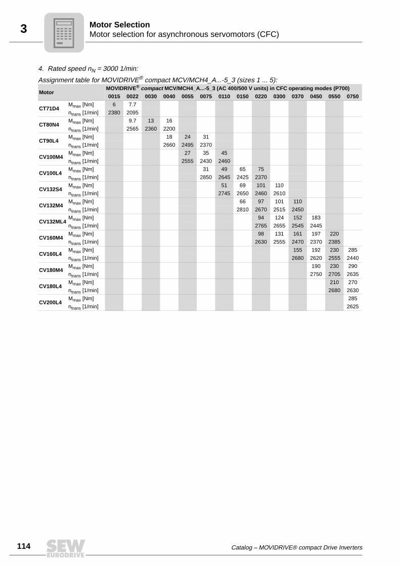
114
3 otor selection for asynchronous servomotors (CFC)otor Selection
4. Rated speed nN = 3000 1/min:
Assignment table for MOVIDRIVE® compact MCV/MCH4_A...-5_3 (sizes 1 ... 5):
MotorMOVIDRIVE® compact MCV/MCH4_A...-5_3 (AC 400/500 V units) in CFC operating modes (P700)
0015 0022 0030 0040 0055 0075 0110 0150 0220 0300 0370 0450 0550 0750
CT71D4Mmax [Nm] 6 7.7
ntrans [1/min] 2380 2095
CT80N4Mmax [Nm] 9.7 13 16
ntrans [1/min] 2565 2360 2200
CT90L4Mmax [Nm] 18 24 31
ntrans [1/min] 2660 2495 2370
CV100M4Mmax [Nm] 27 35 45
ntrans [1/min] 2555 2430 2460
CV100L4Mmax [Nm] 31 49 65 75
ntrans [1/min] 2850 2645 2425 2370
CV132S4Mmax [Nm] 51 69 101 110
ntrans [1/min] 2745 2650 2460 2610
CV132M4Mmax [Nm] 66 97 101 110
ntrans [1/min] 2810 2670 2515 2450
CV132ML4Mmax [Nm] 94 124 152 183
ntrans [1/min] 2765 2655 2545 2445
CV160M4Mmax [Nm] 98 131 161 197 220
ntrans [1/min] 2630 2555 2470 2370 2385
CV160L4Mmax [Nm] 155 192 230 285
ntrans [1/min] 2680 2620 2555 2440
CV180M4Mmax [Nm] 190 230 290
ntrans [1/min] 2750 2705 2635
CV180L4Mmax [Nm] 210 270
ntrans [1/min] 2680 2630
CV200L4Mmax [Nm] 285
ntrans [1/min] 2625
MM
Catalog – MOVIDRIVE® compact Drive Inverters

3Motor selection for asynchronous servomotors (CFC)Motor Selection
Motor tables DT/DV
Characteristic values for delta/star AC 230/400 V / 50 Hz
MotorMN
Mass moment of inertia JM Star (AC 400 V) Delta ∆ (AC 230 V)
without brake with brake In Iq_n1)
1) Applies in the basic speed range up to ntrans.
Id_n1) kT
1) In Iq_n1) Id_n
1) kT1)
[Nm] [10-4 kgm2] [A] [A] [A] [Nm/A] [A] [A] [A] [Nm/A]
DT71D4 2.6 4.6 5.5 1.15 0.95 0.65 2.69 1.99 1.64 1.13 1.56
DT80K4 3.9 6.6 7.5 1.75 1.44 1 2.68 3.03 2.49 1.73 1.55
DT80N4 5.2 8.7 9.6 2.1 1.67 1.27 3.11 3.64 2.89 2.2 1.79
DT90S4 7.5 25 31 2.80 2.39 1.46 3.13 4.85 4.14 2.53 1.81
DT90L4 10.2 34 40 3.55 2.93 2 3.48 6.15 5.07 3.46 2.01
DV100M4 15.0 53 59 4.7 4.12 2.24 3.61 8.14 7.14 3.88 2.09
DV100L4 20.5 65 71 6.3 5.6 2.98 3.66 10.91 9.70 5 2.11
DV112M4 26.9 98 110 8.7 7.85 3.75 3.43 15.1 13.6 6.5 1.98
DV132S4 36.7 146 158 11 9.9 4.7 3.69 19.1 17.2 8.14 2.13
DV132M4 50.1 280 330 15.5 14.2 6.15 3.53 26.9 24.6 10.65 2.04
DV132ML4 61.0 330 380 18.1 16.5 7.46 3.7 31.35 28.6 12.9 2.13
DV160M4 72.9 398 448 22.5 20.3 9.70 3.59 39.0 35.2 16.8 2.07
DV160L4 98.1 925 1060 29.5 26.1 13.7 3.75 51.1 45.28 23.7 2.17
DV180M4 121 1120 1255/13502)
2) Double disc brake
37 21.7 19.1 3.82 64.1 54.9 33.1 2.2
DV180L4 143 1290 1425/15201) 42.5 37.4 20.3 3.83 73.6 64.71 35.1 2.21
DV200L4 195 2340 2475/25702) 55 49.9 23.1 3.91 95.3 86.5 39.9 2.25
DV225S4 240 3010 3145/32402) 67 61.6 26.4 3.9 116 106.7 45.7 2.25
DV225M4 292 3570 3705/38002) 83 74.8 36.1 3.9 143.8 129.5 62.4 2.26
DV250M4 356 6300 6600/67302) 102 91.7 44.7 3.88 176.7 158.8 77.4 2.24
DV280S4 484 8925 9225/93552) 138 120.4 67.5 4.02 239 208.5 116.8 2.32
DV280M4 581 8925 9225/93552) 170 148.9 68.9 3.9 294.5 257.9 119.3 2.25
Catalog – MOVIDRIVE® compact Drive Inverters
115
116
3 otor selection for asynchronous servomotors (CFC)otor Selection
Characteristic values for double-star/star AC 230/460 V / 60 Hz
(according to MG1, NEMA Design B to DT80K4, NEMA Design C from DT80N4)
Motor
Mass moment of inertia JM Star (AC 460 V) Double-star (AC 230 V)
MN without brake with brake In Iq_n1)
1) Applies in the basic speed range up to ntrans.
Id_n1) kT
1) In Iq_n1) Id_n
1) kT1)
[Nm] [10-4 kgm2] [A] [A] [A] [Nm/A] [A] [A] [A] [Nm/A]
DT71D4 2.1 4.6 5.5 1 0.76 0.65 2.74 2 1.52 1.30 1.37
DT80K4 3.1 6.6 7.5 1.45 1.06 0.98 2.92 2.9 2.12 1.96 1.46
DT80N4 4.2 8.7 9.6 1.85 1.39 1.21 3.03 3.7 2.78 2.42 1.51
DT90S4 6.1 25 31 2.6 1.87 1.79 3.25 5.2 3.74 3.58 1.62
DT90L4 8.3 34 40 3.1 2.49 1.84 3.34 6.2 4.98 3.68 1.67
DT100M4 12.1 53 59 4.1 3.59 1.97 3.37 8.2 7.18 3.94 1.69
DT100L4 21 65 71 6.6 5.98 2.78 3.51 13.2 11.96 5.56 1.76
DV112M4 22.1 98 110 7 6.13 3.37 3.61 14 12.26 6.74 1.80
DV132S4 30.5 146 158 9.4 8.61 3.76 3.54 18.8 17.22 7.52 1.77
DV132M4 41.2 280 330 13.7 11.85 6.87 3.48 27.4 23.7 13.74 1.74
DV132ML4 50.5 330 380 16.4 14.41 7.83 3.50 32.8 28.82 15.66 1.75
DV160M4 60.4 398 448 20 17.36 9.92 3.48 40 34.72 19.84 1.74
DV160L4 81.4 925 1060 27 23.24 13.73 3.50 54 46.48 27.46 1.75
DV180M4 100 1120 1255/13502)
2) Double disc brake
31.5 28.06 14.29 3.56 63 56.1 28.58 1.78
DV180L4 119 1290 1425/15202) 40 34.5 20.22 3.45 80 69 40.44 1.72
DV200L4 163 2340 2475/25702) 47.5 44.63 16.25 3.65 95 89.26 32.5 1.83
DV225S4 201 3010 3145/32402) 59 55.14 21 3.65 118 110.3 42 1.82
DV225M4 244 3570 3705/38002) 70 64.6 27 3.78 140 129.2 54 1.89
DV250M4 296 6300 6600/67302) 87 78.45 37.6 3.77 174 156.9 75.2 1.89
DV280S4 402 8925 9225/93552) 118 106.5 50.8 3.77 236 213 101.6 1.89
DV280M4 580 14500 3)
3) On request
162 153 51.7 3.79 324 306 103.4 1.89
MM
Catalog – MOVIDRIVE® compact Drive Inverters

3Motor selection for asynchronous servomotors (CFC)Motor Selection
DT/DV motor selection in connection type delta/star (AC 230/400 V / 50 Hz)
1. Star connection 400 V / 50 Hz or AC 400/690 V / 50 Hz motors in ∆ connection:Motor MOVIDRIVE® compact MCV/MCH4_A...-5_3 (AC 400/500 V units) in CFC operating modes
AC 400 V / 50 Hz 0015 0022 0030 0040 0055 0075 0110 0150 0220 0300 0370 0450 0550 0750
DT80N4Mmax [Nm] 9.3
ntrans [1/min] 922
DT90S4Mmax [Nm] 13.5
ntrans [1/min] 1011
DT90L4Mmax [Nm] 18.3 18.3
ntrans [1/min] 973 1088
DV100M4Mmax [Nm] 26.8 26.8 26.8
ntrans [1/min] 941 1043 1056
DV100L4Mmax [Nm] 36.8 36.8 36.8
ntrans [1/min] 890 1005 1011
DV112M4Mmax [Nm] 47.1 48.4 48.4
ntrans [1/min] 915 1030 1062
DV132S4Mmax [Nm] 66.1 66.1 66.1
ntrans [1/min] 1011 1171 1222
DV132M4Mmax [Nm] 81.7 90.2 90.2
ntrans [1/min] 1011 1145 1152
DV132ML4Mmax [Nm] 110 110
ntrans [1/min] 1082 1165
DV160M4Mmax [Nm] 125 131 131
ntrans [1/min] 986 1133 1197
DV160L4Mmax [Nm] 172 177 177
ntrans [1/min] 1050 1306 1350
DV180M4Mmax [Nm] 217 217 217
ntrans [1/min] 1222 1453 1517
DV180L4Mmax [Nm] 231.2 258 258 258
ntrans [1/min] 1018 1152 1299 1370
DV200L4Mmax [Nm] 339.5 351 351 351
ntrans [1/min] 1018 1171 1350 1466
DV225S4Mmax [Nm]
Note: The maximum torque Mmax is limited to 180 % of the rated motor torque MN. The data is based on a supply voltage of AC 400 V.
414.7 433 433 433
ntrans [1/min] 954 1082 1222 1363
DV225M4Mmax [Nm] 502.6 526 526
ntrans [1/min] 1037 1146 1344
DV250M4Mmax [Nm] 586.5 641
ntrans [1/min] 1018 1133
DV280S4Mmax [Nm] 735.4
ntrans [1/min] 1082
Catalog – MOVIDRIVE® compact Drive Inverters
117
118
3 otor selection for asynchronous servomotors (CFC)otor Selection
2. Motor AC 230/400 V / 50 Hz in delta connection:
Assignment table for MOVIDRIVE® compact MCV/MCH4_A...-5_3 (sizes 1 ... 5):Motor MOVIDRIVE® compact MCV/MCH4_A...-5_3 (AC 400/500 V units) in CFC operating modes
∆ AC 230 V / 50 Hz 0015 0022 0030 0040 0055 0075 0110 0150 0220 0300 0370 0450 0550 0750
DT71D4Mmax [Nm] 4.6
ntrans [1/min] 2054
DT80K4Mmax [Nm] 6.9 6.9
ntrans [1/min] 1850 1869
DT80N4Mmax [Nm] 9.3 9.3
ntrans [1/min] 1869 2080
DT90S4Mmax [Nm] 13.5 13.5 13.5
ntrans [1/min] 1971 2246 2304
DT90L4Mmax [Nm] 18.3 18.3 18.3
ntrans [1/min] 1946 2342 2387
DV100M4Mmax [Nm] 26.8 26.8 26.8
ntrans [1/min] 1862 2214 2298
DV100L4Mmax [Nm] 36.8 36.8 36.8
ntrans [1/min] 1779 2080 2188
DV112M4Mmax [Nm] 45.5 48.4 48.4
ntrans [1/min] 1779 2163 2195
DV132S4Mmax [Nm] 66.1 66.1 66.1
ntrans [1/min] 2086 2458 2496
DV132M4Mmax [Nm] 90.2 90.2
ntrans [1/min] 1939 2310
DV132ML4Mmax [Nm] 110 110
ntrans [1/min] 2176 2291
DV160M4Mmax [Nm] 131 131 131
ntrans [1/min] 1894 2246 2348
DV160L4Mmax [Nm]
Note: The maximum torque Mmax is limited to 180 % of the rated motor torque MN. The data is based on a supply voltage of AC 400 V.
177 177 177
ntrans [1/min] 2010 2336 2560
DV180M4Mmax [Nm] 217 217 217
ntrans [1/min] 2061 2445 2720
DV180L4Mmax [Nm] 258 258 258
ntrans [1/min] 1837 2131 2458
DV200L4Mmax [Nm] 341.8 351
ntrans [1/min] 1843 2182
DV225S4Mmax [Nm] 425
ntrans [1/min] 1715
MM
Catalog – MOVIDRIVE® compact Drive Inverters
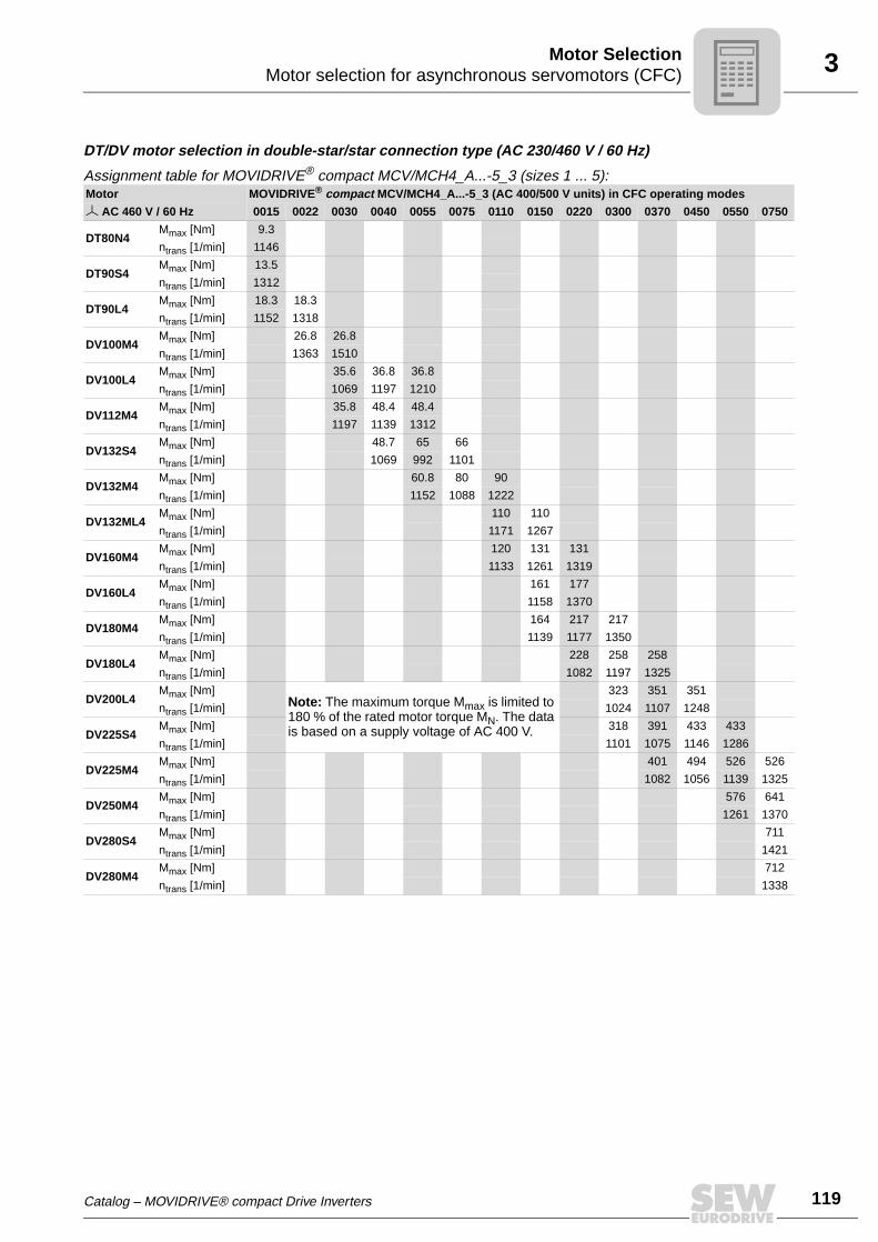
3Motor selection for asynchronous servomotors (CFC)Motor Selection
DT/DV motor selection in double-star/star connection type (AC 230/460 V / 60 Hz)
Assignment table for MOVIDRIVE® compact MCV/MCH4_A...-5_3 (sizes 1 ... 5):Motor MOVIDRIVE® compact MCV/MCH4_A...-5_3 (AC 400/500 V units) in CFC operating modes
AC 460 V / 60 Hz 0015 0022 0030 0040 0055 0075 0110 0150 0220 0300 0370 0450 0550 0750
DT80N4Mmax [Nm] 9.3
ntrans [1/min] 1146
DT90S4Mmax [Nm] 13.5
ntrans [1/min] 1312
DT90L4Mmax [Nm] 18.3 18.3
ntrans [1/min] 1152 1318
DV100M4Mmax [Nm] 26.8 26.8
ntrans [1/min] 1363 1510
DV100L4Mmax [Nm] 35.6 36.8 36.8
ntrans [1/min] 1069 1197 1210
DV112M4Mmax [Nm] 35.8 48.4 48.4
ntrans [1/min] 1197 1139 1312
DV132S4Mmax [Nm] 48.7 65 66
ntrans [1/min] 1069 992 1101
DV132M4Mmax [Nm] 60.8 80 90
ntrans [1/min] 1152 1088 1222
DV132ML4Mmax [Nm] 110 110
ntrans [1/min] 1171 1267
DV160M4Mmax [Nm] 120 131 131
ntrans [1/min] 1133 1261 1319
DV160L4Mmax [Nm] 161 177
ntrans [1/min] 1158 1370
DV180M4Mmax [Nm] 164 217 217
ntrans [1/min] 1139 1177 1350
DV180L4Mmax [Nm] 228 258 258
ntrans [1/min] 1082 1197 1325
DV200L4Mmax [Nm]
Note: The maximum torque Mmax is limited to 180 % of the rated motor torque MN. The data is based on a supply voltage of AC 400 V.
323 351 351
ntrans [1/min] 1024 1107 1248
DV225S4Mmax [Nm] 318 391 433 433
ntrans [1/min] 1101 1075 1146 1286
DV225M4Mmax [Nm] 401 494 526 526
ntrans [1/min] 1082 1056 1139 1325
DV250M4Mmax [Nm] 576 641
ntrans [1/min] 1261 1370
DV280S4Mmax [Nm] 711
ntrans [1/min] 1421
DV280M4Mmax [Nm] 712
ntrans [1/min] 1338
Catalog – MOVIDRIVE® compact Drive Inverters
119
120
3 otor selection for asynchronous servomotors (CFC)otor Selection
2. Motors AC 230/460 V / 60 Hz in double-star connection:
Assignment table for MOVIDRIVE® compact MCV/MCH4_A...-5_3 (sizes 1 ... 5):Motor MOVIDRIVE® compact MCV/MCH4_A...-5_3 (AC 400/500 V units) in CFC operating modes
AC 230 V / 60 Hz 0015 0022 0030 0040 0055 0075 0110 0150 0220 0300 0370 0450 0550 0750
DT71D4Mmax [Nm] 4.6
ntrans [1/min] 2989
DT80K4Mmax [Nm] 7 7
ntrans [1/min] 2688 2822
DT80N4Mmax [Nm] 8.3 9.3 9.3
ntrans [1/min] 2586 2874 2970
DT90S4Mmax [Nm] 11.9 13.5 13.5
ntrans [1/min] 2637 2931 3462
DT90L4Mmax [Nm] 16.4 18.3 18.3
ntrans [1/min] 2605 3014 3354
DV100M4Mmax [Nm] 23.1 26 26.8
ntrans [1/min] 3142 3360 3680
DV100L4Mmax [Nm] 31.5 36.8 36.8
ntrans [1/min] 2470 2605 3014
DV112M4Mmax [Nm] 41.4 48.4
ntrans [1/min] 2534 2989
DV132S4Mmax [Nm] 62.4 66
ntrans [1/min] 2234 2573
DV132M4Mmax [Nm] 80 90.2
ntrans [1/min] 2349 2707
DV132ML4Mmax [Nm] 110 110
ntrans [1/min] 2496 2880
DV160M4Mmax [Nm] 115 131 131
ntrans [1/min] 2451 2688 2963
DV160L4Mmax [Nm] 150 177 177
ntrans [1/min] 2458 2515 2918
DV180M4Mmax [Nm] 189 217 217
ntrans [1/min] 2355 2458 2771
DV180L4Mmax [Nm] 220 258 258
ntrans [1/min] 2285 2291 2720
DV200L4Mmax [Nm]
Note: The maximum torque Mmax is limited to 180 % of the rated motor torque MN. The data is based on a supply voltage of AC 400 V.
281 350
ntrans [1/min] 2208 2163
DV225S4Mmax [Nm] 346
ntrans [1/min] 2291
DV225M4Mmax [Nm] 354
ntrans [1/min] 2278
MM
Catalog – MOVIDRIVE® compact Drive Inverters
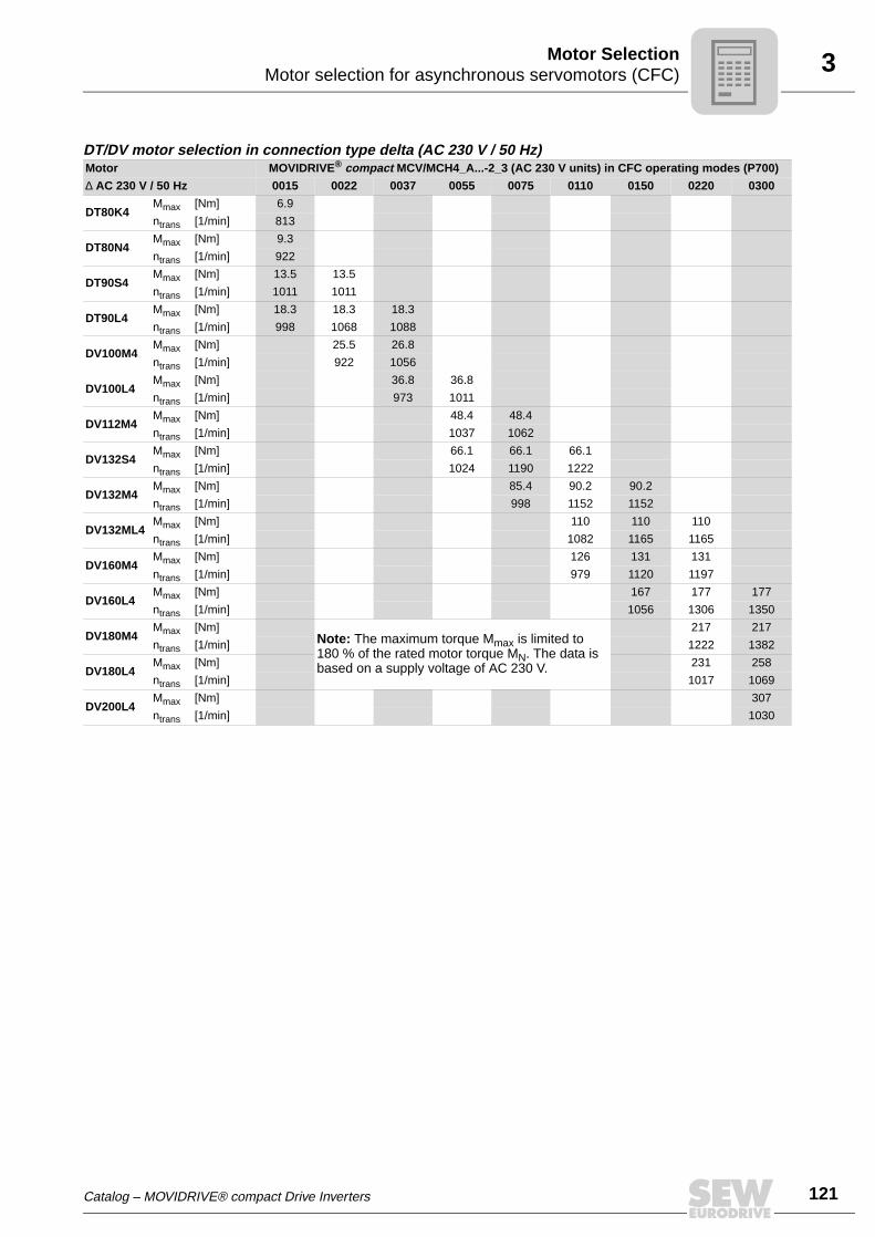
3Motor selection for asynchronous servomotors (CFC)Motor Selection
DT/DV motor selection in connection type delta (AC 230 V / 50 Hz)Motor MOVIDRIVE® compact MCV/MCH4_A...-2_3 (AC 230 V units) in CFC operating modes (P700)
∆ AC 230 V / 50 Hz 0015 0022 0037 0055 0075 0110 0150 0220 0300
DT80K4Mmax [Nm] 6.9
ntrans [1/min] 813
DT80N4Mmax [Nm] 9.3
ntrans [1/min] 922
DT90S4Mmax [Nm] 13.5 13.5
ntrans [1/min] 1011 1011
DT90L4Mmax [Nm] 18.3 18.3 18.3
ntrans [1/min] 998 1068 1088
DV100M4Mmax [Nm] 25.5 26.8
ntrans [1/min] 922 1056
DV100L4Mmax [Nm] 36.8 36.8
ntrans [1/min] 973 1011
DV112M4Mmax [Nm] 48.4 48.4
ntrans [1/min] 1037 1062
DV132S4Mmax [Nm] 66.1 66.1 66.1
ntrans [1/min] 1024 1190 1222
DV132M4Mmax [Nm] 85.4 90.2 90.2
ntrans [1/min] 998 1152 1152
DV132ML4Mmax [Nm] 110 110 110
ntrans [1/min] 1082 1165 1165
DV160M4Mmax [Nm] 126 131 131
ntrans [1/min] 979 1120 1197
DV160L4Mmax [Nm] 167 177 177
ntrans [1/min] 1056 1306 1350
DV180M4Mmax [Nm]
Note: The maximum torque Mmax is limited to 180 % of the rated motor torque MN. The data is based on a supply voltage of AC 230 V.
217 217
ntrans [1/min] 1222 1382
DV180L4Mmax [Nm] 231 258
ntrans [1/min] 1017 1069
DV200L4Mmax [Nm] 307
ntrans [1/min] 1030
Catalog – MOVIDRIVE® compact Drive Inverters
121
122
3 otor selection for asynchronous servomotors (CFC)otor Selection
DT/DV motor selection in connection type double-star (AC 230 V / 60 Hz)
Motors AC 230/460 V / 60 Hz in double-star connection:Motor MOVIDRIVE® compact MCV/MCH4_A...-2_3 (AC 230 V units) in CFC operating modes (P700)
AC 230 V / 60 Hz 0015 0022 0037 0055 0075 0110 0150 0220 0300
DT80N4Mmax [Nm] 9.3
ntrans [1/min] 1146
DT90S4Mmax [Nm] 13.5 13.5
ntrans [1/min] 1267 1338
DT90L4Mmax [Nm] 17.2 18.3 18.3
ntrans [1/min] 1146 1210 1325
DV100M4Mmax [Nm] 20.7 26.8
ntrans [1/min] 1459 1517
DV100L4Mmax [Nm] 36.8 36.8
ntrans [1/min] 1056 1210
DV112M4Mmax [Nm] 37.2 48.4 48.4
ntrans [1/min] 1190 1248 1338
DV132S4Mmax [Nm] 57 66.1 66.1
ntrans [1/min] 1030 1062 1120
DV132M4Mmax [Nm] 71.7 90.2 90.2
ntrans [1/min] 1114 1165 1222
DV132ML4Mmax [Nm] 106 110
ntrans [1/min] 1101 1235
DV160M4Mmax [Nm] 104 131 131
ntrans [1/min] 1165 1146 1318
DV160L4Mmax [Nm]
Note: The maximum torque Mmax is limited to 180 % of the rated motor torque MN. The data is based on a supply voltage of AC 230 V.
133 177 177
ntrans [1/min] 1190 1267 1395
DV180M4Mmax [Nm] 208 217
ntrans [1/min] 1101 1203
DV180L4Mmax [Nm] 195 236
ntrans [1/min] 1107 1075
DV200L4Mmax [Nm] 210 253
ntrans [1/min] 1082 1062
DV225S4Mmax [Nm] 247
ntrans [1/min] 1133
MM
Catalog – MOVIDRIVE® compact Drive Inverters

3Motor Selection for Synchronous Servomotors (SERVO)Motor Selection
3.3 Motor Selection for Synchronous Servomotors (SERVO)
Motor characteristics
The demands made on a servo drive include speed dynamics, stable speed and posi-tioning accuracy. CM/DS motors with MOVIDRIVE® meet these requirements.
Technically speaking, these are synchronous motors with permanent magnets on therotor and a mounted resolver. The required characteristics, namely constant torque overa wide speed range (up to 5500 1/min), a high speed and control range (up to 1:3000)and a high overload capacity (more than 3 × M0), are achieved using control byMOVIDRIVE®. The mass moment of inertia of the servomotor is lower than that of theasynchronous motor. This means it is ideally suited to applications requiring dynamicspeeds.
M0 and Mmax are determined by the motor. The attainable Mmax can also be less,depending on the inverter.
Refer to the DS/CM motor tables for the values for M0.
Refer to the DS/CM motor selection tables for the values for Mmax.
NOTEThe torque limit (M limit) is set automatically by the startup function of theMOVITOOLS® operating software. Do not increase this automatically set value!
We recommend always using the latest version of MOVITOOLS® for startup. The latestMOVITOOLS® version can be downloaded from our homepage (www.sew-euro-drive.de).
01652CENFigure 28: Speed/torque characteristic curve of the CM/DS servomotor
1 Continuous torque
2 Maximum torque
0
Mmax
0
1
2
M0
M [lb.in]
n [rpm]nN
Catalog – MOVIDRIVE® compact Drive Inverters
123
124
3 otor Selection for Synchronous Servomotors (SERVO)otor Selection
Basic recommen-dations
For the SEW motors, the motor data required for the SERVO operating modes is storedin MOVIDRIVE®.
Speed is the correcting variable in the SERVO operating modes with speed control.Torque is the correcting variable in the SERVO operating modes with torque control(SERVO & M-CONTROL).
SERVO mode with speed control
There is no need to differentiate between the load types quadratic, dynamic and staticwhen performing project planning for the SERVO operating mode. Project planning fora synchronous motor is carried out in accordance with the following requirements:
1. Effective torque requirement at average application speed.
Meff < M0
The operating point must lie below the characteristic curve for the continuous torque(Figure 28, curve 1). If this operating point lies above the characteristic curve for self-cooling, the continuous torque of the DFY series can be increased by 60 % by forcedcooling.
2. Maximum torque needed across the speed curve.
Mmax < Mdyn_Mot
This operating point must lie below the characteristic curve for the maximum torqueof the motor/MOVIDRIVE® combination (Figure 28, curve 2).
3. Maximum speed
The maximum speed must not be configured higher than the rated speed of the mo-tor. Planetary gear units should be used for speeds greater than 3000 1/min due tothe high input speed.
nmax ≤ nN
SERVO operation with torque control (SERVO & M-CTRL)
This operating mode allows the servomotor to be controlled directly with torque control.The setpoint sources of the speed-controlled SERVO mode can also be used for torquecontrol. All speed setpoint sources (except for bus setpoints) are interpreted as currentsetpoint sources. The settings for evaluating the analog input (→ P11_, parameter de-scription) also remain in effect. The fixed setpoints (P16_, P17_) can be entered in theunits [1/min] or [%IN_inverter] as required (→ MOVITOOLS®).
The following relationship exists between the units:
3000 1/min = 150 % rated inverter current
The torque at the output shaft of the servomotor can be calculated using the followingformula:
04976AEN
M0 Continuous static torque according to the motor table DS/CM
I0 Continuous static current according to motor table DS/CM
MM
I= x
0
0
150 % x In_inverter
x nsetp
3000 1/min
MM
Catalog – MOVIDRIVE® compact Drive Inverters

3Motor Selection for Synchronous Servomotors (SERVO)Motor Selection
DS/CM motor table
Characteristic values at Vmax = AC 230 V / AC 400 V Without forced
cooling fanWith forced cooling
fan VR Mass moment of inertia JM
nN Motor M0 I01)
1) For DS/CM synchronous servomotors with AC 400 V system voltage
I02)
2) For DS/CM synchronous servomotors with AC 230 V system voltage
M0_VR I0_VR1) I0_VR
2) Imax1) Imax
2) without brake with brake
[1/min] [Nm] [A] [A] [Nm] [A] [A] [A] [A] [10-4 kgm2]
2000
CM71S 5.0 2.2 3.95 7.3 3.2 5.7 8.8 15.8 4.85 6.89
CM71M 6.5 3.0 5.3 9.4 4.2 7.7 12.0 21.0 6.27 8.31
CM71L 9.5 4.2 7.4 13.8 6.1 10.7 16.8 29.5 9.1 11.1
CM90S 11.0 4.9 8.7 16.0 7.1 12.6 19.6 35.0 14.3 19.8
CM90M 14.5 6.9 12.1 21.0 10.0 17.5 28.0 48.5 18.6 24.1
CM90L 21.0 9.9 17.1 30.5 14.4 25.0 40.0 68.0 27.1 32.6
CM112S 23.5 10.0 18.0 34.0 14.5 26.0 40.0 72 67.4 87.5
CM112M 31.0 13.5 24.5 45.0 19.6 35.5 54.0 98 87.4 108
CM112L 45.0 20.0 35.5 65.0 29.0 51.0 80.0 142 128 148
CM112H 68.0 30.5 52.0 95.0 42.5 73.0 122 208 189 209
3000
DS56M 1.0 1.65 1.65 - - - 6.6 6.6 0.47 0.85
DS56L 2.0 2.4 2.4 - - - 9.6 9.6 0.82 1.2
DS56H 4.0 2.8 4.7 - - - 11.2 19 1.53 1.88
CM71S 5.0 3.3 5.9 7.3 4.8 8.6 13.2 23.5 4.85 6.89
CM71M 6.5 4.3 7.6 9.4 6.2 11.0 17.2 30.5 6.27 8.31
CM71L 9.5 6.2 11.1 13.8 9.0 16.1 25.0 44.5 9.1 11.1
CM90S 11.0 7.3 12.7 16.0 10.6 18.4 30.0 51 14.3 19.8
CM90M 14.5 10.1 17.4 21.0 14.6 25.0 40.0 70 18.6 24.1
CM90L 21.0 14.4 25.5 30.5 21.0 37.0 58.0 102 27.1 32.6
CM112S 23.5 15.0 27.0 34.0 22.0 39.0 60.0 108 67.4 87.5
CM112M 31.0 20.5 35.0 45.0 30.0 51.0 82.0 140 87.4 108
CM112L 45.0 30.0 48.0 65.0 44.0 70.0 120 192 128 148
CM112H 68.0 43.0 73.0 95.0 60.0 102 172 292 189 209
4500
DS56M 1.0 1.65 1.65 - - - 6.6 6.6 0.47 0.85
DS56L 2.0 2.4 - - - - 9.6 - 0.82 1.2
DS56H 4.0 4.0 - - - - 16.0 - 1.53 1.88
CM71S 5.0 4.9 8.5 7.3 7.2 12.3 20.0 34 4.85 6.89
CM71M 6.5 6.6 11.3 9.4 9.6 16.4 26.0 45 6.27 8.31
CM71L 9.5 9.6 17.1 13.8 14.0 25.0 38.0 68 9.1 11.1
CM90S 11.0 11.1 18.9 16.0 16.2 27.5 44.0 76 14.3 19.8
CM90M 14.5 14.7 26.0 21.0 21.5 37.5 59.0 104 18.6 24.1
CM90L 21.0 21.6 39.0 30.5 31.5 57 86.0 156 27.1 32.6
CM112S 23.5 22.5 38.5 34.0 32.5 56 90.0 154 67.4 87.5
CM112M 31.0 30.0 54.0 45.0 44.0 78 120 216 87.4 108
CM112L 45.0 46.0 78.0 65.0 67.0 113 184 312 128 148
CM112H 68.0 66.0 - 95.0 92.0 - 264 - 189 209
6000
DS56M 1.0 1.65 - - - - 6.6 - 0.47 0.85
DS56L 2.0 2.75 - - - - 11.0 - 0.82 1.2
DS56H 4.0 5.3 - - - - 21.0 - 1.53 1.88
CM71S 5.0 6.5 11.6 7.3 7.2 16.8 26.0 46.5 4.85 6.89
CM71M 6.5 8.6 14.1 9.4 9.6 20.5 34.0 56 6.27 8.31
CM71L 9.5 12.5 21.5 13.8 14.0 31.0 50.0 86 9.1 11.1
CM90S 11.0 14.5 23.5 16.0 16.2 34.0 58.0 94 14.3 19.8
CM90M 14.5 19.8 37.0 21.0 21.5 54 79.0 148 18.6 24.1
CM90L 21.0 29.5 51.0 30.5 31.5 74 118.0 204 27.1 32.6
Catalog – MOVIDRIVE® compact Drive Inverters
125
126
3 otor Selection for Synchronous Servomotors (SERVO)otor Selection
DS/CM motor selection (AC 400 V system voltage)
1. Rated speed nN = 2000 1/min:
2. Rated speed nN = 3000 1/min:
NOTEAdditional project planning instructions and information on the DS/CM synchronousservomotors can be found in the "Servo Gearmotors" catalog, which can be orderedfrom SEW-EURODRIVE.
MotorMOVIDRIVE® compact MCS/MCH4_A...-5_3 (AC 400/500 V units) in SERVO operating modes (P700)
0015 0022 0030 0040 0055 0075 0110 0150 0220 0300 0370 0450
CM71S Mmax [Nm] 12.7 15.9 16.5
CM71M Mmax [Nm] 12.7 16.7 19.8 21.5
CM71L Mmax [Nm] 13.5 18.2 22.5 28.4 31.4
CM90S Mmax [Nm] 13.4 18.4 23.2 30.6 38.2 39.4
CM90M Mmax [Nm] 12.6 17.3 21.9 29.5 38.0 46.9 52.5
CM90L Mmax [Nm] 17.5 22.2 30.1 39.3 49.6 70.3 75.8
CM112S Mmax [Nm] 19.3 24.6 33.4 43.6 54.8 76.2 81.9
CM112M Mmax [Nm] 23.9 32.6 42.9 54.7 79.3 99.6 108.0
CM112L Mmax [Nm] 42.0 53.9 80.3 104.9 141.5 156.8
CM112H Mmax [Nm] 53.2 80.1 106.5 150.3 189.2 220.1 237.0
MotorMOVIDRIVE® compact MCS/MCH4_A...-5_3 (AC 400/500 V units) in SERVO operating modes (P700)
0015 0022 0030 0040 0055
DS56M Mmax [Nm] 3.5 3.8
DS56L Mmax [Nm] 4.9 6.6 7.6
DS56H Mmax [Nm] 8.5 11.5 14.3 15.0
CM71S Mmax [Nm] 8.9 11.9 14.3 16.5
CM71M Mmax [Nm] 9.0 12.2 15.1 19.1 21.5
CM71L Mmax [Nm] 9.2 12.6 15.9 21.0 26.2
CM90S Mmax [Nm] 9.0 12.4 15.7 21.2 27.4
CM90M Mmax [Nm] 11.8 15.0 20.4 26.6
CM90L Mmax [Nm] 20.7 27.3
CM112S Mmax [Nm] 22.2 29.3
CM112M Mmax [Nm] 28.2
MotorMOVIDRIVE® compact MCS/MCH4_A...-5_3 (AC 400/500 V units) in SERVO operating modes (P700)
0075 0110 0150 0220 0300 0370 0450 0550 0750
CM71L Mmax [Nm] 30.8 31.5
CM90S Mmax [Nm] 34.0 39.2
CM90M Mmax [Nm] 33.7 47.8 51.6
CM90L Mmax [Nm] 34.7 51.1 65.6 75.6
CM112S Mmax [Nm] 37.4 54.8 69.8 81.9
CM112M Mmax [Nm] 36.2 54.0 70.7 95.7 108.0
CM112L Mmax [Nm] 35.8 53.9 71.6 101.0 126.9 147.4 156.8
CM112H Mmax [Nm] 56.6 75.7 108.6 139.9 167.0 197.1 223.2 237.0
MM
Catalog – MOVIDRIVE® compact Drive Inverters

3Motor Selection for Synchronous Servomotors (SERVO)Motor Selection
3. Rated speed nN = 4500 1/min:
4. Rated speed nN = 6000 1/min:
MotorMOVIDRIVE® compact MCS/MCH4_A...-5_3 (AC 400/500 V units) in SERVO operating modes (P700)
0015 0022 0030 0040
DS56M Mmax [Nm] 3.5 3.8
DS56L Mmax [Nm] 4.9 6.6 7.6
DS56H Mmax [Nm] 6.0 8.2 10.3 13.7
CM71S Mmax [Nm] 6.1 8.3 10.4 13.4
CM71M Mmax [Nm] 5.9 8.1 10.2 13.6
CM71L Mmax [Nm] 8.2 10.4 14.0
CM90S Mmax [Nm] 10.4 14.1
CM90M Mmax [Nm] 14.0
MotorMOVIDRIVE® compact MCS/MCH4_A...-5_3 (AC 400/500 V units) in SERVO operating modes (P700)
0055 0075 0110 0150 0220 0300 0370 0450 0550 0750 0900 1100
DS56H Mmax [Nm] 15.2
CM71S Mmax [Nm] 16.1 16.5
CM71M Mmax [Nm] 17.1 20.3 21.3
CM71L Mmax [Nm] 18.1 22.5 30.3 31.2
CM90S Mmax [Nm] 18.4 23.4 33.6 39.2
CM90M Mmax [Nm] 18.4 23.5 34.6 44.5 52.1
CM90L Mmax [Nm] 18.2 23.3 34.7 45.8 63.4 75.0
CM112S Mmax [Nm] 19.5 25.0 37.4 49.2 67.5 81.9
CM112M Mmax [Nm] 24.6 37.1 49.4 69.6 87.4 101.5 108.0
CM112L Mmax [Nm] 35 46.8 67.2 86.9 104.1 123.5 140.7 156.8
CM112H Mmax [Nm] 70.9 92.5 112.1 135.5 157.7 189.4 231.6 237.0
MotorMOVIDRIVE® compact MCS/MCH4_A...-5_3 (AC 400/500 V units) in SERVO operating modes (P700)
0015 0022 0030 0040 0055 0075 0110 0150 0220 0300 0370 0450
DS56M Mmax [Nm] 3.5 3.8
DS56L Mmax [Nm] 4.3 5.8 7.3 7.6
DS56H Mmax [Nm] 4.5 6.2 7.9 10.5 13.6 15.1
CM71S Mmax [Nm] 4.6 6.3 8.0 10.6 13.3 15.8 16.5
CM71M Mmax [Nm] 6.2 7.9 10.6 13.7 16.8 21.3
CM71L Mmax [Nm] 8.0 10.8 14.1 17.9 25.2 30.7 31.4
CM90S Mmax [Nm] 10.8 14.2 18.1 26.6 34.2 39.4
CM90M Mmax [Nm] 13.7 17.5 26.1 34.3 46.9 51.9
CM90L Mmax [Nm] 17.1 25.6 33.9 48.0 60.9 71.3 75.2
Catalog – MOVIDRIVE® compact Drive Inverters
127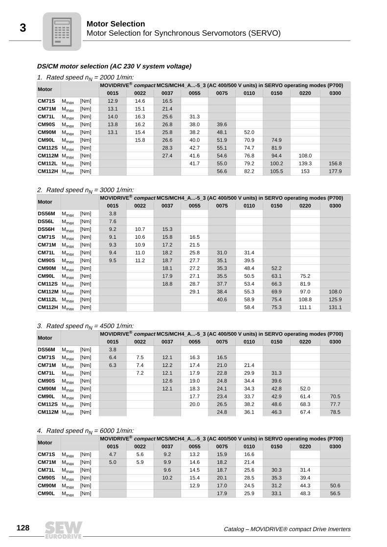
128
3 otor Selection for Synchronous Servomotors (SERVO)otor Selection
DS/CM motor selection (AC 230 V system voltage)
1. Rated speed nN = 2000 1/min:
2. Rated speed nN = 3000 1/min:
3. Rated speed nN = 4500 1/min:
4. Rated speed nN = 6000 1/min:
MotorMOVIDRIVE® compact MCS/MCH4_A...-5_3 (AC 400/500 V units) in SERVO operating modes (P700)
0015 0022 0037 0055 0075 0110 0150 0220 0300
CM71S Mmax [Nm] 12.9 14.6 16.5
CM71M Mmax [Nm] 13.1 15.1 21.4
CM71L Mmax [Nm] 14.0 16.3 25.6 31.3
CM90S Mmax [Nm] 13.8 16.2 26.8 38.0 39.6
CM90M Mmax [Nm] 13.1 15.4 25.8 38.2 48.1 52.0
CM90L Mmax [Nm] 15.8 26.6 40.0 51.9 70.9 74.9
CM112S Mmax [Nm] 28.3 42.7 55.1 74.7 81.9
CM112M Mmax [Nm] 27.4 41.6 54.6 76.8 94.4 108.0
CM112L Mmax [Nm] 41.7 55.0 79.2 100.2 139.3 156.8
CM112H Mmax [Nm] 56.6 82.2 105.5 153 177.9
MotorMOVIDRIVE® compact MCS/MCH4_A...-5_3 (AC 400/500 V units) in SERVO operating modes (P700)
0015 0022 0037 0055 0075 0110 0150 0220 0300
DS56M Mmax [Nm] 3.8
DS56L Mmax [Nm] 7.6
DS56H Mmax [Nm] 9.2 10.7 15.3
CM71S Mmax [Nm] 9.1 10.6 15.8 16.5
CM71M Mmax [Nm] 9.3 10.9 17.2 21.5
CM71L Mmax [Nm] 9.4 11.0 18.2 25.8 31.0 31.4
CM90S Mmax [Nm] 9.5 11.2 18.7 27.7 35.1 39.5
CM90M Mmax [Nm] 18.1 27.2 35.3 48.4 52.2
CM90L Mmax [Nm] 17.9 27.1 35.5 50.5 63.1 75.2
CM112S Mmax [Nm] 18.8 28.7 37.7 53.4 66.3 81.9
CM112M Mmax [Nm] 29.1 38.4 55.3 69.9 97.0 108.0
CM112L Mmax [Nm] 40.6 58.9 75.4 108.8 125.9
CM112H Mmax [Nm] 58.4 75.3 111.1 131.1
MotorMOVIDRIVE® compact MCS/MCH4_A...-5_3 (AC 400/500 V units) in SERVO operating modes (P700)
0015 0022 0037 0055 0075 0110 0150 0220 0300
DS56M Mmax [Nm] 3.8
CM71S Mmax [Nm] 6.4 7.5 12.1 16.3 16.5
CM71M Mmax [Nm] 6.3 7.4 12.2 17.4 21.0 21.4
CM71L Mmax [Nm] 7.2 12.1 17.9 22.8 29.9 31.3
CM90S Mmax [Nm] 12.6 19.0 24.8 34.4 39.6
CM90M Mmax [Nm] 12.1 18.3 24.1 34.3 42.8 52.0
CM90L Mmax [Nm] 17.7 23.4 33.7 42.9 61.4 70.5
CM112S Mmax [Nm] 20.0 26.5 38.2 48.6 68.3 77.7
CM112M Mmax [Nm] 24.8 36.1 46.3 67.4 78.5
MotorMOVIDRIVE® compact MCS/MCH4_A...-5_3 (AC 400/500 V units) in SERVO operating modes (P700)
0015 0022 0037 0055 0075 0110 0150 0220 0300
CM71S Mmax [Nm] 4.7 5.6 9.2 13.2 15.9 16.6
CM71M Mmax [Nm] 5.0 5.9 9.9 14.6 18.2 21.4
CM71L Mmax [Nm] 9.6 14.5 18.7 25.6 30.3 31.4
CM90S Mmax [Nm] 10.2 15.4 20.1 28.5 35.3 39.4
CM90M Mmax [Nm] 12.9 17.0 24.5 31.2 44.3 50.6
CM90L Mmax [Nm] 17.9 25.9 33.1 48.3 56.5
MM
Catalog – MOVIDRIVE® compact Drive Inverters

4Changes compared to the previous versionIndex of Changes
4 Index of Changes4.1 Changes compared to the previous version
The following section lists the changes made to the individual sections from edition04/2002, publication number 10538313 (EN).
System description
• The new option USB11A has been included in the subsection "System overview."
Technical data and dimension drawings
• All the tightening torques according to EN 61800-5-1 have been included in the cat-alog.
• The subsection "Interface adapter type USB11A / option DKG11A" has been added.
• The subsection "MOVIDRIVE® MDR60A regenerative power supply units" has beencompletely revised.
• The DBG11B-15 version has been included in the subsection "DBG11B keypad."
• The trip currents IF have been updated in the subsection "BW.. braking resistors."The braking resistors BW...-T and BW...-P have been added.
• Type ND030-023 has been included in the subsection "ND.. line chokes." The dimen-sion drawings for the line chokes have been revised.
• The dimension drawings have been revised in the subsection "HF.. output filters."
• The subsection "Prefabricated cables" has been completely revised.
Motor selection • The motor tables have been revised in the subsection "Motor selection for asynchro-nous servomotors (CFC)." The motor/inverter assignments have been updated.
Catalog – MOVIDRIVE® compact Drive Inverters
129
5
130
Index
5 Index
Numerics5 V encoder supply DWI11A ...............................67
AApplication modules
Overview .......................................................16Application version
Additional functions ......................................12
BBlock circuit diagram for MOVIDRIVE® compact .9Braking resistors BW... / BW...-T / BW...-P .........68
Assignment to AC 230 V units ......................72Assignment to AC 400/500 V units ...............69Flat design ....................................................68Parallel connection .......................................69Technical data for braking resistors BW...-T /
BW...-P ............................................72UL and cUL approval ....................................68Wire and grid resistors ..................................68
BS touch guard ...................................................74
CC-Tick approval ...................................................25CE marking .........................................................25Control modes, general description ......................7
DDBG11B keypad .................................................64Dimension drawing
Line filter NF... ..............................................79Dimension drawings
Basic unit size 1 ............................................53Basic unit size 2 ............................................54Basic unit size 3 ............................................55Basic unit size 4 ............................................56Basic unit size 5 ............................................57Braking resistors BW... / BW...-T / BW...-P ..73DBG11B keypad ...........................................64DKB11A heat sink for braking resistors in
flatpack design .................................75HD... output choke ........................................80HF... output filters .........................................83Line choke ND.. ............................................76Serial interface USS21A ...............................65Touch guard BS ............................................74
DKB11A ..............................................................75DWI11A ...............................................................67
EElectronic cam ....................................................12
GGeneral description ...............................................7GOST-R certificate ..............................................25
IIndex of changes .............................................. 129
Changes compared to the previous version ............................ 129
Interface adapterUSB11A ....................................................... 66
Internal synchronous operationDescription ................................................... 14
IPOSplus® ......................................................... 63General description ........................................ 7
LLine choke ND.. .................................................. 76Line filter NF...-... ................................................ 78
MMotor selection for asynchronous AC motors (VFC)
Basic recommendations ...................... 98, 106Dynamic applications ................................... 99Examples for delta/star
AC 230/400 V / 50 Hz ................... 102Motor selection for delta AC 230 V / 50 Hz 104Motor selection for
delta/star AC 230/400 V / 50 Hz ... 101Motor selection for
double-star 230 V / 60 Hz ............. 105Motor selection for double-star/star
AC 230/460 V / 60 Hz ................... 103Speed/torque characteristic curve ............... 99Voltage/frequency characteristic curve ........ 98
Motor selection for asynchronous servomotors (CFC)
CT/CV motor selection ............................... 111CT/CV motor selection for rated speed
1200 1/min .................................... 111CT/CV motor selection for rated speed
1700 1/min .................................... 112CT/CV motor selection for rated speed
2100 1/min .................................... 113CT/CV motor selection for rated speed
3000 1/min .................................... 114CT/CV motor table ..................................... 110DT/DV motor selection for delta
AC 230 V / 50 Hz .......................... 121DT/DV motor selection for delta/star
AC 230/400 V / 50 Hz ................... 117DT/DV motor selection in double star
AC 230 V / 60 Hz .......................... 122DT/DV/D motor selection in double-star/star
AC 230/460 V / 60 Hz ................... 119Magnetizing current ................................... 107Motor characteristics .................................. 106Motor tables DT/DV ................................... 115Notes for CT/CV motors ............................ 109
Catalog – MOVIDRIVE® compact Drive Inverters

5Index
Torque control ............................................108Motor selection for synchronous servomotors (SERVO)
Basic recommendations .............................124DS/CM motor selection AC 230 V,
rated speed 2000 1/min .................128DS/CM motor selection AC 230 V,
rated speed 3000 1/min .................128DS/CM motor selection AC 230 V,
rated speed 4500 1/min .................128DS/CM motor selection AC 230 V,
rated speed 6000 1/min .................128DS/CM motor selection AC 400 V,
rated speed 2000 1/min .................126DS/CM motor selection AC 400 V,
rated speed 3000 1/min .................126DS/CM motor selection AC 400 V,
rated speed 4500 1/min .................127DS/CM motor selection AC 400 V,
rated speed 6000 1/min .................127DS/CM motor table .....................................125Motor characteristics ..................................123Torque control ............................................124
MOVIDRIVE® MDR60A regenerative power supply unit
Cable sets for the DC link connection ..........62Description ....................................................58Dimension drawings .....................................61General technical data ..................................59Technical data for sizes 3, 4, 6 .....................60UL approval ..................................................58
MOVILINK® ..........................................................7MOVITOOLS® operating software .....................24
OOption DKG11A ..................................................66Output choke HD... .............................................80Output filter HF... .................................................81Overview of MOVIDRIVE® compact units ............8Overview of series and variants ............................7
PPrefabricated cables ...........................................85
Cable sets for connection to X14/X15 onMCV / MCS / MCH basic units ........88
Meaning of the symbols ................................88Overview of the cable sets for connection at
X14 on MCV/MCS basic unit ...........96Overview of the cable sets for connection at
X15 on the MCH basic unit ..............94Overview of the cable sets for connection at
X15 on the MCS basic unit ..............92Overview of the cable sets for connection at
X15 on the MCV basic unit ..............89
SSerial interface USS21A .....................................65System bus (SBus)
General description ........................................ 7System overview
Communication and technology components 5Power components ........................................ 4
System bus (SBus)Technical data ....................................... 47, 51
T
Techincal dataPrefabricated cables .................................... 85
Technical data5 V encoder supply DWI11A ........................ 67AC 230 V units
Size 1 .................................................... 38Size 2 .................................................... 40Size 3 .................................................... 42Size 4 .................................................... 44
AC 400/500 V unitsSize 1 .................................................... 28Size 2 .................................................... 30Size 3 .................................................... 32Size 4 .................................................... 34Size 5 .................................................... 36
BS touch guard ............................................ 74BW... braking resistors / BW...-T / BW...-P .. 68DBG11B keypad .......................................... 64DKB11A heat sink for brake resistors in
flatpack design ................................ 75Electronics data for MCH4_A basic units .... 50Eletronics data for MCF/MCV/MCS4_A
basic units ....................................... 46General technical data ................................. 27Interface adapter USB11A ........................... 66IPOSplus® ................................................... 63Line choke ND.. option ................................ 76Line filter NF...-... ......................................... 78Output choke HD... ...................................... 80Output filter HF... ......................................... 81Serial interface USS21A .............................. 65Systembus (SBus) ................................. 47, 51
Technology functionElectronic cam ............................................. 12
U
UL/cUL approval ................................................ 25Unit designation ................................................. 26Unit functions and properties ............................. 10Unit variants MCF/MCV/MCS/MCH ..................... 6Unit versions
Application version ......................................... 6Standard version ............................................ 6
USB11A ............................................................. 66
Catalog – MOVIDRIVE® compact Drive Inverters 131

132
Address Directory
Address DirectoryGermany
HeadquartersProductionSales
Bruchsal SEW-EURODRIVE GmbH & Co KGErnst-Blickle-Straße 42 D-76646 BruchsalP.O. BoxPostfach 3023 • D-76642 Bruchsal
Tel. +49 7251 75-0Fax +49 7251 75-1970http://[email protected]
Production Graben SEW-EURODRIVE GmbH & Co KGErnst-Blickle-Straße 1 D-76676 Graben-NeudorfP.O. BoxPostfach 1220 • D-76671 Graben-Neudorf
Tel. +49 7251 75-0Fax +49 7251 75-2970
Östringen SEW-EURODRIVE Östringen GmbHFranz-Gurk-Straße 2 D-76684 ÖstringenP.O. BoxPostfach 1174 • D-76677 Östringen
Tel. +49 7253 92540Fax +49 7253 [email protected]
Service Competence Center
CentralGear units / Motors
SEW-EURODRIVE GmbH & Co KGErnst-Blickle-Straße 1 D-76676 Graben-Neudorf
Tel. +49 7251 75-1710Fax +49 7251 [email protected]
CentralElectronics
SEW-EURODRIVE GmbH & Co KGErnst-Blickle-Straße 42 D-76646 Bruchsal
Tel. +49 7251 75-1780Fax +49 7251 [email protected]
North SEW-EURODRIVE GmbH & Co KGAlte Ricklinger Straße 40-42 D-30823 Garbsen (near Hannover)
Tel. +49 5137 8798-30Fax +49 5137 [email protected]
East SEW-EURODRIVE GmbH & Co KGDänkritzer Weg 1D-08393 Meerane (near Zwickau)
Tel. +49 3764 7606-0Fax +49 3764 [email protected]
South SEW-EURODRIVE GmbH & Co KGDomagkstraße 5D-85551 Kirchheim (near München)
Tel. +49 89 909552-10Fax +49 89 [email protected]
West SEW-EURODRIVE GmbH & Co KGSiemensstraße 1D-40764 Langenfeld (near Düsseldorf)
Tel. +49 2173 8507-30Fax +49 2173 [email protected]
Drive Service Hotline / 24 Hour Service +49 180 5 SEWHELP+49 180 5 7394357
Technical Offices Augsburg SEW-EURODRIVE GmbH & Co KGAugust-Wessels-Straße 29D-86156 Augsburg
Tel. +49 821 22779-10Fax +49 821 [email protected]
Berlin SEW-EURODRIVE GmbH & Co KGLilienthalstraße 3a D-12529 Schönefeld
Tel. +49 33762 2266-30Fax +49 33762 [email protected]
Bodensee SEW-EURODRIVE GmbH & Co KGBurgbergring 91D-88662 Überlingen
Tel. +49 7551 9226-30Fax +49 7551 [email protected]
Bremen SEW-EURODRIVE GmbH & Co KGBornstr.19 ... 22 D-28195 Bremen
Tel. +49 421 33918-10Fax +49 421 [email protected]
Dortmund SEW-EURODRIVE GmbH & Co KGHildastraße 10D-44145 Dortmund
Tel. +49 231 912050-10Fax +49 231 [email protected]
Dresden SEW-EURODRIVE GmbH & Co KGHauptstraße 32 D-01445 Radebeul
Tel. +49 351 26338-0Fax +49 351 [email protected]
Erfurt SEW-EURODRIVE GmbH & Co KGBlumenstraße 70 D-99092 Erfurt
Tel. +49 361 21709-70Fax +49 361 [email protected]
Güstrow SEW-EURODRIVE GmbH & Co KGThünenweg 19 D-18273 GüstrowP.O. BoxPostfach 1216 • D-18262 Güstrow
Tel. +49 3843 8557-80Fax +49 3843 [email protected]
01/2007

Address Directory
Hamburg SEW-EURODRIVE GmbH & Co KGBramfelder Straße 119 D-23305 Hamburg
Tel. +49 40 298109-60Fax +49 40 [email protected]
Hannover/Garbsen
SEW-EURODRIVE GmbH & Co KGAlte Ricklinger Str.40-42 D-30823 GarbsenP.O. BoxPostfach 1104 53 • D-30804 Garbsen
Tel. +49 5137 8798-10Fax +49 5137 [email protected]
Heilbronn SEW-EURODRIVE GmbH & Co KGZeppelinstraße 7 D-74357 BönnigheimP.O. BoxPostfach 68 • D-74355 Bönnigheim
Tel. +49 7143 8738-0Fax +49 7143 [email protected]
Herford SEW-EURODRIVE GmbH & Co KGRadewiger Straße 21 D-32052 HerfordP.O. BoxPostfach 4108 • D-32025 Herford
Tel. +49 5221 9141-0Fax +49 5221 [email protected]
Karlsruhe SEW-EURODRIVE GmbH & Co KGEttlinger Weg 2 D-76467 Bietigheim P.O. BoxPostfach 43 • D-76463 Bietigheim
Tel. +49 7245 9190-10Fax +49 7245 [email protected]
Kassel SEW-EURODRIVE GmbH & Co KGLange Straße 14D-34253 Lohfelden
Tel. +49 561 95144-80Fax +49 561 [email protected]
Koblenz SEW-EURODRIVE GmbH & Co KGBahnstraße 17a D-56743 Mendig
Tel. +49 2652 9713-30Fax +49 2652 [email protected]
Lahr SEW-EURODRIVE GmbH & Co KG Europastraße 3D-77933 Lahr / Schwarzwald
Tel. +49 7821 90999-60Fax +49 7821 [email protected]
Langenfeld SEW-EURODRIVE GmbH & Co KG Siemensstraße 1 D-40764 Langenfeld
Tel. +49 2173 8507-10Fax +49 2173 [email protected]
Magdeburg SEW-EURODRIVE GmbH & Co KGBurgstraße 7 D-39326 Wolmirstedt
Tel. +49 39201 7004-1Fax +49 39201 [email protected]
Mannheim SEW-EURODRIVE GmbH & Co KGRadeberger Straße 2 D-68309 Mannheim
Tel. +49 621 71683-10Fax +49 621 [email protected]
München SEW-EURODRlVE GmbH & Co KG Domagkstraße 5 D-85551 Kirchheim
Tel. +49 89 90955-110Fax +49 89 [email protected]
Münster SEW-EURODRIVE GmbH & Co KGVon-Vincke-Straße 14 D-48143 Münster
Tel. +49 251 41475-11Fax +49 251 [email protected]
Nürnberg SEW-EURODRIVE GmbH & Co KGPlattenäckerweg 6 D-90455 Nürnberg
Tel. +49 911 98884-50Fax +49 911 [email protected]
Regensburg SEW-EURODRIVE GmbH & Co KGIm Gewerbepark A15 D-93059 Regensburg
Tel. +49 941 46668-68Fax +49 941 [email protected]
Rhein-Main SEW-EURODRIVE GmbH & Co KGNiederstedter Weg 5 D-61348 Bad Homburg
Tel. +49 6172 9617-0Fax +49 6172 [email protected]
Stuttgart SEW-EURODRIVE GmbH & Co KGFriedrich-List-Straße 46D-70771 Leinfelden-Echterdingen
Tel. +49 711 16072-0Fax +49 711 [email protected]
Ulm SEW-EURODRIVE GmbH & Co KGDieselstraße 14 D-89160 Dornstadt
Tel. +49 7348 9885-0 Fax +49 7348 [email protected]
Germany
01/2007 133
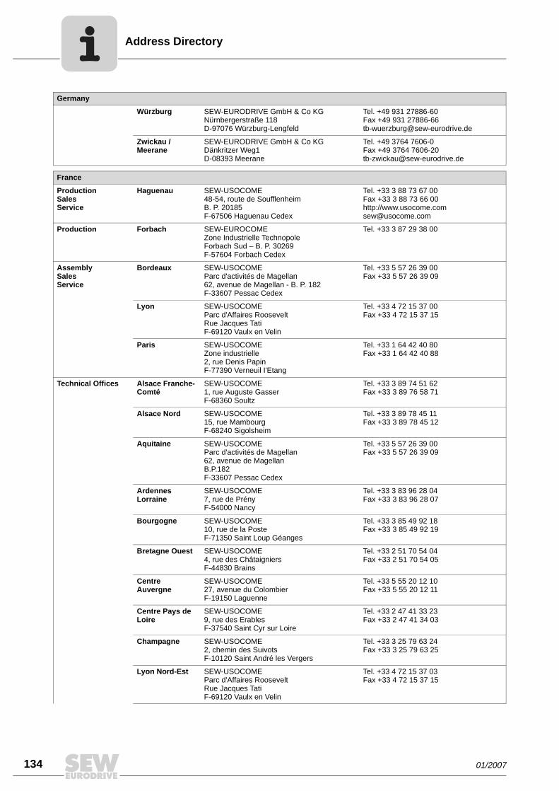
134
Address Directory
Würzburg SEW-EURODRIVE GmbH & Co KGNürnbergerstraße 118D-97076 Würzburg-Lengfeld
Tel. +49 931 27886-60Fax +49 931 [email protected]
Zwickau / Meerane
SEW-EURODRIVE GmbH & Co KG Dänkritzer Weg1 D-08393 Meerane
Tel. +49 3764 7606-0Fax +49 3764 [email protected]
France
ProductionSalesService
Haguenau SEW-USOCOME 48-54, route de Soufflenheim B. P. 20185F-67506 Haguenau Cedex
Tel. +33 3 88 73 67 00 Fax +33 3 88 73 66 00http://[email protected]
Production Forbach SEW-EUROCOME Zone Industrielle TechnopoleForbach Sud – B. P. 30269F-57604 Forbach Cedex
Tel. +33 3 87 29 38 00
AssemblySalesService
Bordeaux SEW-USOCOME Parc d'activités de Magellan62, avenue de Magellan - B. P. 182F-33607 Pessac Cedex
Tel. +33 5 57 26 39 00Fax +33 5 57 26 39 09
Lyon SEW-USOCOME Parc d'Affaires RooseveltRue Jacques TatiF-69120 Vaulx en Velin
Tel. +33 4 72 15 37 00Fax +33 4 72 15 37 15
Paris SEW-USOCOME Zone industrielle 2, rue Denis Papin F-77390 Verneuil I'Etang
Tel. +33 1 64 42 40 80Fax +33 1 64 42 40 88
Technical Offices Alsace Franche-Comté
SEW-USOCOME1, rue Auguste GasserF-68360 Soultz
Tel. +33 3 89 74 51 62Fax +33 3 89 76 58 71
Alsace Nord SEW-USOCOME15, rue MambourgF-68240 Sigolsheim
Tel. +33 3 89 78 45 11Fax +33 3 89 78 45 12
Aquitaine SEW-USOCOMEParc d'activités de Magellan 62, avenue de Magellan B.P.182F-33607 Pessac Cedex
Tel. +33 5 57 26 39 00Fax +33 5 57 26 39 09
Ardennes Lorraine
SEW-USOCOME7, rue de Prény F-54000 Nancy
Tel. +33 3 83 96 28 04Fax +33 3 83 96 28 07
Bourgogne SEW-USOCOME10, rue de la PosteF-71350 Saint Loup Géanges
Tel. +33 3 85 49 92 18Fax +33 3 85 49 92 19
Bretagne Ouest SEW-USOCOME4, rue des ChâtaigniersF-44830 Brains
Tel. +33 2 51 70 54 04Fax +33 2 51 70 54 05
Centre Auvergne
SEW-USOCOME27, avenue du ColombierF-19150 Laguenne
Tel. +33 5 55 20 12 10Fax +33 5 55 20 12 11
Centre Pays de Loire
SEW-USOCOME9, rue des ErablesF-37540 Saint Cyr sur Loire
Tel. +33 2 47 41 33 23Fax +33 2 47 41 34 03
Champagne SEW-USOCOME2, chemin des SuivotsF-10120 Saint André les Vergers
Tel. +33 3 25 79 63 24Fax +33 3 25 79 63 25
Lyon Nord-Est SEW-USOCOMEParc d'Affaires RooseveltRue Jacques TatiF-69120 Vaulx en Velin
Tel. +33 4 72 15 37 03Fax +33 4 72 15 37 15
Germany
01/2007

Address Directory
Lyon Ouest SEW-USOCOMEParc d'Affaires RooseveltRue Jacques TatiF-69120 Vaulx en Velin
Tel. +33 4 72 15 37 04Fax +33 4 72 15 37 15
Lyon Sud-Est SEW-USOCOMEMontée de la GarenneF-26750 Génissieux
Tel. +33 4 75 05 65 95Fax +33 4 75 05 65 96
Nord SEW-USOCOME348, rue du CalvaireF-59213 Bermerain Cidex 102
Tel. +33 3 27 27 07 88Fax +33 3 27 27 24 41
Normandie SEW-USOCOME5 rue de la LimareF-14250 Brouay
Tel. +33 2 31 37 92 86Fax +33 2 31 74 68 15
Paris Est SEW-USOCOMERésidence Le Bois de Grâce 2, allée des Souches VertesF-77420 Champs sur Marne
Tel. +33 1 64 68 40 50Fax +33 1 64 68 45 00
Paris Ouest SEW-USOCOME42 avenue Jean JaurèsF-78580 Maule
Tel. +33 1 30 90 89 86Fax +33 1 30 90 93 15
Paris Picardie SEW-USOCOME25 bis, rue KléberF-92300 Levallois Perret
Tel. +33 1 41 05 92 74Fax +33 1 41 05 92 75
Paris Sud SEW-USOCOME6. chemin des BergersLieu-dit MarchaisF-91410 Roinville sous Dourdan
Tel. +33 1 60 81 10 56Fax +33 1 60 81 10 57
Provence SEW-USOCOMERésidence Les Hespérides Bât. B267, boulevard des AlpesF-13012 Marseille
Tel. +33 4 91 18 00 11Fax +33 4 91 18 00 12
Pyrénées SEW-USOCOME271, Lieu-dit NinautF-31190 Caujac
Tel. +33 5 61 08 15 85Fax +33 5 61 08 16 44
Sud-Atlantique SEW-USOCOME12, rue des PinsonsF-44120 Vertou
Tel. +33 2 40 80 32 23Fax +33 2 40 80 32 13
Algeria
Sales Alger Réducom 16, rue des Frères ZaghnounBellevue El-Harrach16200 Alger
Tel. +213 21 8222-84Fax +213 21 8222-84
Argentina
AssemblySalesService
Buenos Aires SEW EURODRIVE ARGENTINA S.A.Centro Industrial Garin, Lote 35Ruta Panamericana Km 37,51619 Garin
Tel. +54 3327 4572-84Fax +54 3327 [email protected]
Australia
AssemblySalesService
Melbourne SEW-EURODRIVE PTY. LTD.27 Beverage DriveTullamarine, Victoria 3043
Tel. +61 3 9933-1000Fax +61 3 9933-1003http://[email protected]
Sydney SEW-EURODRIVE PTY. LTD.9, Sleigh Place, Wetherill Park New South Wales, 2164
Tel. +61 2 9725-9900Fax +61 2 [email protected]
Perth SEW-EURODRIVE PTY. LTD. 105 Robinson Avenue Belmont, W.A. 6104
Tel. +61 8 9478-2688Fax +61 8 [email protected]
Brisbane SEW-EURODRIVE PTY.LTD.1 /34 Collinsvale StRocklea, Queensland, 4106
Tel. +61 7 3272-7900Fax +61 7 [email protected]
France
01/2007 135

136
ddress Directory
Technical Offices Adelaide SEW-EURODRIVE PTY. LTD. Unit 1/601 Anzac HighwayGlenelg, S.A. 5045
Tel. +61 8 8294-8277Fax +61 8 [email protected]
Townsville SEW-EURODRIVE PTY. LTD.12 Leyland StreetGarbutt, QLD 4814
Tel. +61 7 4779 4333Fax +61 7 4779 [email protected]
Austria
AssemblySalesService
Wien SEW-EURODRIVE Ges.m.b.H. Richard-Strauss-Strasse 24A-1230 Wien
Tel. +43 1 617 55 00-0Fax +43 1 617 55 00-30http://[email protected]
Technical Offices Linz SEW-EURODRIVE Ges.m.b.H. Reuchlinstr. 6/3A-4020 Linz
Tel. +43 732 655 109-0Fax +43 732 655 [email protected]
Graz SEW-EURODRIVE Ges.m.b.H.Grabenstraße 231A-8045 Graz
Tel. +43 316 685 756-0Fax +43 316 685 [email protected]
Dornbirn SEW-EURODRIVE Ges.m.b.H.Lustenauerstraße 27/1A-6850 Dornbirn
Tel. +43 5572 3725 99-0Fax +43 5572 3725 [email protected]
Bangladesh
Sales Dhaka Triangle Trade InternationalBldg-5, Road-2, Sec-3, Uttara Model TownDhaka-1230 Bangladesh
Tel. +880 2 8912246Fax +880 2 8913344
Belgium
AssemblySalesService
Brüssel SEW Caron-Vector S.A.Avenue Eiffel 5B-1300 Wavre
Tel. +32 10 231-311Fax +32 10 231-336http://[email protected]
Technical Office Vlaanderen SEW Caron-Vector S.A.Industrieweg 112-114B-9032 Gent (Wondelgem)
Tel. +32 92 273-452Fax +32 92 274-155
Brazil
ProductionSalesService
Sao Paulo SEW-EURODRIVE Brasil Ltda.Avenida Amâncio Gaiolli, 50Caixa Postal: 201-07111-970Guarulhos/SP - Cep.: 07251-250
Tel. +55 11 6489-9133Fax +55 11 6480-3328http://[email protected]
Additional addresses for service in Brazil provided on request!
Bulgaria
Sales Sofia BEVER-DRIVE GmbHBogdanovetz Str.1BG-1606 Sofia
Tel. +359 2 9151160Fax +359 2 [email protected]
Cameroon
Sales Douala Electro-ServicesRue Drouot AkwaB.P. 2024Douala
Tel. +237 4322-99Fax +237 4277-03
Canada
AssemblySalesService
Toronto SEW-EURODRIVE CO. OF CANADA LTD. 210 Walker Drive Bramalea, Ontario L6T3W1
Tel. +1 905 791-1553Fax +1 905 791-2999http://[email protected]
Vancouver SEW-EURODRIVE CO. OF CANADA LTD.7188 Honeyman Street Delta. B.C. V4G 1 E2
Tel. +1 604 946-5535Fax +1 604 [email protected]
Australia
A
01/2007

Address Directory
Montreal SEW-EURODRIVE CO. OF CANADA LTD.2555 Rue Leger LaSalle, Quebec H8N 2V9
Tel. +1 514 367-1124Fax +1 514 [email protected]
Additional addresses for service in Canada provided on request!
Chile
AssemblySalesService
Santiago de Chile
SEW-EURODRIVE CHILE LTDA.Las Encinas 1295Parque Industrial Valle GrandeLAMPARCH-Santiago de ChileP.O. BoxCasilla 23 Correo Quilicura - Santiago - Chile
Tel. +56 2 75770-00Fax +56 2 75770-01http://[email protected]
China
ProductionAssemblySalesService
Tianjin SEW-EURODRIVE (Tianjin) Co., Ltd.No. 46, 7th Avenue, TEDA Tianjin 300457
Tel. +86 22 25322612Fax +86 22 [email protected]://www.sew-eurodrive.com.cn
AssemblySalesService
Suzhou SEW-EURODRIVE (Suzhou) Co., Ltd.333, Suhong Middle RoadSuzhou Industrial ParkJiangsu Province, 215021P. R. China
Tel. +86 512 62581781Fax +86 512 [email protected]
Guangzhou SEW-EURODRIVE (Guangzhou) Co., Ltd.No. 9, JunDa RoadEast Section of GETDDGuangzhou 510530P. R. China
Tel. +86 20 82267890Fax +86 20 [email protected]
Shenyang SEW-EURODRIVE (Shenyang) Co., Ltd.10A-2, 6th RoadShenyang Economic Technological ¬Development AreaShenyang, 110141P. R. China
Tel. +86 24 22521596Fax +86 24 [email protected]
Colombia
AssemblySalesService
Bogotá SEW-EURODRIVE COLOMBIA LTDA. Calle 22 No. 132-60Bodega 6, Manzana BSantafé de Bogotá
Tel. +57 1 54750-50Fax +57 1 54750-44http://[email protected]
Croatia
SalesService
Zagreb KOMPEKS d. o. o.PIT Erdödy 4 IIHR 10 000 Zagreb
Tel. +385 1 4613-158Fax +385 1 [email protected]
Czech Republic
Sales Praha SEW-EURODRIVE CZ S.R.O.Business Centrum Praha Luzna 591CZ-16000 Praha 6 - Vokovice
Tel. +420 220121234Fax +420 220121237http://[email protected]
Technical Offices Brno SEW-EURODRIVE CZ S.R.O.Krenova 52CZ -60200 Brno
Tel. +420 543256151 + 543256163Fax +420 543256845
Hradec Kralove SEW-EURODRIVE CZ S.R.O.Technicka Kancelar - vychodni CechySvermovaCZ-53374 Horni Jeleni
Tel. +420 466673711Fax +420 466673634
Klatovy SEW-EURODRIVE CZ S.R.O.Technical Office KlatovyKollarova 528CZ-33901 Klatovy 3
Tel. +420 376310729Fax +420 376310725
Canada
01/2007
137
138
ddress Directory
Denmark
AssemblySalesService
Kopenhagen SEW-EURODRIVEA/SGeminivej 28-30DK-2670 Greve
Tel. +45 43 9585-00Fax +45 43 9585-09http://[email protected]
Egypt
SalesService
Cairo Copam Egypt for Engineering & Agencies33 EI Hegaz ST, Heliopolis, Cairo
Tel. +20 2 2566-299 + 1 23143088Fax +20 2 2594-757http://www.copam-egypt.com/ [email protected]
Estonia
Sales Tallin ALAS-KUUL ASReti tee 4EE-75301 Peetri küla, Rae vald, Harjumaa
Tel. +372 6593230Fax +372 [email protected]
Finland
AssemblySalesService
Lahti SEW-EURODRIVE OYVesimäentie 4FIN-15860 Hollola 2
Tel. +358 201 589-300Fax +358 3 [email protected]://www.sew-eurodrive.fi
Technical Offices Helsinki SEW-EURODRIVE OYLuutnantinaukio 5C LT2 FIN-00410 Helsinki
Tel. +358 201 589-300Fax + 358 9 [email protected]
Vaasa SEW-EURODRIVE OYKauppapuistikko 11 EFIN-65100 Vaasa
Tel. +358 3 589-300Fax +358 6 3127-470
Gabon
Sales Libreville Electro-ServicesB.P. 1889Libreville
Tel. +241 7340-11Fax +241 7340-12
Great Britain
AssemblySalesService
Normanton SEW-EURODRIVE Ltd.Beckbridge Industrial Estate P.O. Box No.1GB-Normanton, West- Yorkshire WF6 1QR
Tel. +44 1924 893-855Fax +44 1924 893-702http://[email protected]
Technical Offices London SEW-EURODRIVE Ltd.764 Finchely Road, Temple FortuneGB-London N.W.11 7TH
Tel. +44 20 8458-8949Fax +44 20 8458-7417
Midlands SEW-EURODRIVE Ltd.5 Sugar Brook court,Aston Road,Bromsgrove, WorcsB60 3EX
Tel. +44 1527 877-319Fax +44 1527 575-245
Scotland SEW-EURODRIVE Ltd.Scottish OfficeNo 37 Enterprise HouseSpringkerse Business ParkGB-Stirling FK7 7UF Scotland
Tel. +44 17 8647-8730Fax +44 17 8645-0223
Greece
SalesService
Athen Christ. Boznos & Son S.A.12, Mavromichali StreetP.O. Box 80136, GR-18545 Piraeus
Tel. +30 2 1042 251-34 Fax +30 2 1042 251-59http://[email protected]
Technical Office Thessaloniki Christ. Boznos & Son S.A.Maiandrou 15562 24 Evosmos, Thessaloniki
Tel. +30 2 310 7054-00Fax +30 2 310 [email protected]
A
01/2007

Address Directory
Hong Kong
AssemblySalesService
Hong Kong SEW-EURODRIVE LTD.Unit No. 801-806, 8th FloorHong Leong Industrial ComplexNo. 4, Wang Kwong Road Kowloon, Hong Kong
Tel. +852 2 7960477 + 79604654Fax +852 2 [email protected]
Hungary
SalesService
Budapest SEW-EURODRIVE Kft.H-1037 BudapestKunigunda u. 18
Tel. +36 1 437 06-58Fax +36 1 437 [email protected]
Iceland
Sales Reykjavik Vélaverk ehf.Bolholti 8, 3h.IS - 105 Reykjavik
Tel. +354 568 3536Fax +354 568 [email protected]
India
AssemblySalesService
Baroda SEW-EURODRIVE India Pvt. Ltd.Plot No. 4, GidcPor Ramangamdi • Baroda - 391 243Gujarat
Tel. +91 265 2831086Fax +91 265 2831087http://[email protected]
Technical Offices Bangalore SEW-EURODRIVE India Private Limited308, Prestige Centre Point7, Edward RoadBangalore
Tel. +91 80 22266565Fax +91 80 [email protected]
Calcutta SEW EURODRIVE INDIA PVT. LTD.Juthika Apartment, Flat No. B111/1, Sunny ParkCalcutta - 700 019
Tel. +91 33 24615820Fax +91 33 [email protected]
Chennai SEW-EURODRIVE India Private LimitedF2, 1st Floor, Sarvamangala IndiraNew No. 67, Bazullah RoadChennai - 600 017
Tel. +91 44 28144461Fax +91 44 [email protected]
Hyderabad SEW-EURODRIVE India Pvt. Limited408, 4th Floor, Meridian PlaceGreen Park RoadAmerpeetHyderabad
Tel. +91 40 23414698Fax +91 40 [email protected]
Mumbai SEW-EURODRIVE India Private Limited312 A, 3rd Floor, Acme PlazaAndheri Kurla Road, Andheri (E)Mumbai
Tel. +91 22 28348440Fax +91 22 [email protected]
New Delhi SEW-EURODRIVE India Private Limited303 Kirti Deep,2-Nangal Raya Business CentreNew Delhi 110 046
Tel. +91 11 28521566Fax +91 11 [email protected]
Pune SEW-EURODRIVE India Private Limited206, Metro House 7Mangaldas RoadPune 411001, Maharashtra
Tel. +91 20 26111054Fax +91 20 26132337 [email protected]
Indonesia
Technical Office Jakarta SEW-EURODRIVE Pte Ltd.Jakarta Liaison Office, Menara Graha KencanaJl. Perjuangan No. 88, LT 3 B, Kebun Jeruk, Jakarta 11530
Tel. +62 21 5359066Fax +62 21 5363686
Ireland
SalesService
Dublin Alperton Engineering Ltd. 48 Moyle RoadDublin Industrial EstateGlasnevin, Dublin 11
Tel. +353 1 830-6277Fax +353 1 [email protected]
01/2007
139
140
ddress Directory
Israel
Sales Tel-Aviv Liraz Handasa Ltd. Ahofer Str 34B / 22858858 Holon
Tel. +972 3 5599511Fax +972 3 [email protected]
Italy
AssemblySalesService
Milano SEW-EURODRIVE di R. Blickle & Co.s.a.s.Via Bernini,14 I-20020 Solaro (Milano)
Tel. +39 02 96 9801Fax +39 02 96 799781http://[email protected]
Technical Offices Bologna SEW-EURODRIVE di R. Blickle & Co.s.a.s. Via Emilia,172 I-40064 Ozzano dell'Emilia (Bo)
Tel. +39 051 796-660Fax +39 051 796-595
Caserta SEW-EURODRIVE di R. Blickle & Co.s.a.s. Viale Carlo III Km. 23,300I-81020 S. Nicola la Strada (Caserta)
Tel. +39 0823 219011Fax +39 0823 421414
Firenze RIMAVia Einstein, 14I-50013 Campi Bisenzio (Firenze)
Tel. +39 055 898 58-21 Fax +39 055 898 58-30
Pescara SEW-EURODRIVE di R. Blickle & Co.s.a.s. Via Emilia,172 I-40064 Ozzano dell'Emilia (Bo)
Tel. +39 051 796-660Fax +39 051 796-595
Torino SEW-EURODRIVE di R. Blickle & Co.s.a.s. Filiale Torinoc.so Unione Sovietica 612/15 - int. CI-11035 Torino
Tel. +39 011 3473780Fax +39 011 3473783
Verona SEW-EURODRIVE di R. Blickle & Co.s.a.s. Via P. Sgulmero, 27/AI-37132 Verona
Tel. +39 045 97-7722Fax +39 045 97-6079
Ivory Coast
Sales Abidjan SICASte industrielle et commerciale pour l'Afrique165, Bld de MarseilleB.P. 2323, Abidjan 08
Tel. +225 2579-44Fax +225 2584-36
Japan
AssemblySalesService
Toyoda-cho SEW-EURODRIVE JAPAN CO., LTD 250-1, Shimoman-no,IwataShizuoka 438-0818
Tel. +81 538 373811Fax +81 538 373814http://[email protected]
Technical Offices Fukuoka SEW-EURODRIVE JAPAN CO., LTD.C-go, 5th-floor, Yakuin-Hiruzu-Bldg. 1-5-11, Yakuin, Chuo-kuFukuoka, 810-0022
Tel. +81 92 713-6955Fax +81 92 [email protected]
Osaka SEW-EURODRIVE JAPAN CO., LTD. B-Space EIRAI Bldg., 3rd Floor 1-6-9 Kyoumachibori,Nishi-ku, Osaka, 550-0003
Tel. +81 6 6444--8330Fax +81 6 [email protected]
Tokyo SEW-EURODRIVE JAPAN CO., LTD.Izumi-Bldg. 5 F 3-2-15 Misaki-cho Chiyoda-ku, Tokyo101-0061
Tel. +81 3 3239-0469Fax +81 3 [email protected]
Korea
AssemblySalesService
Ansan-City SEW-EURODRIVE KOREA CO., LTD. B 601-4, Banweol Industrial Estate Unit 1048-4, Shingil-DongAnsan 425-120
Tel. +82 31 492-8051Fax +82 31 492-8056http://[email protected]
Busan SEW-EURODRIVE KOREA Co., Ltd.No. 1720 - 11, Songjeong - dongGangseo-kuBusan 618-270
Tel. +82 51 832-0204Fax +82 51 [email protected]
A
01/2007

Address Directory
Technical Offices Daegu SEW-EURODRIVE KOREA Co., Ltd.No.1108 Sungan officetel 87-36, Duryu 2-dong, Dalseo-kuDaegu 704-712
Tel. +82 53 650-7111Fax +82 53 [email protected]
DaeJeon SEW-EURODRIVE KOREA Co., Ltd.No. 2017, Hongin offictel536-9, Bongmyung-dong, Yusung-kuDaejeon 305-301
Tel. +82 42 828-6461Fax +82 42 [email protected]
Kwangju SEW-EURODRIVE KOREA Co., Ltd. 4fl., Shinhyun B/D 96-16 Unam-dong, Buk-kuKwangju 500-170
Tel. +82 62 511-9172Fax +82 62 [email protected]
Seoul SEW-EURODRIVE KOREA Co., Ltd. No.1104 Sunkyung officetel 106-4 Kuro 6-dong, Kuro-kuSeoul 152-054
Tel. +82 2 862-8051Fax +82 2 [email protected]
Latvia
Sales Riga SIA Alas-KuulKatlakalna 11CLV-1073 Riga
Tel. +371 7139253Fax +371 7139386http://[email protected]
Lebanon
Sales Beirut Gabriel Acar & Fils sarlB. P. 80484Bourj Hammoud, Beirut
Tel. +961 1 4947-86 +961 1 4982-72+961 3 2745-39Fax +961 1 4949-71 [email protected]
Lithuania
Sales Alytus UAB IrsevaNaujoji 19LT-62175 Alytus
Tel. +370 315 79204Fax +370 315 [email protected]://www.sew-eurodrive.lt
Luxembourg
AssemblySalesService
Brüssel CARON-VECTOR S.A.Avenue Eiffel 5B-1300 Wavre
Tel. +32 10 231-311Fax +32 10 231-336http://[email protected]
Malaysia
AssemblySalesService
Johore SEW-EURODRIVE SDN BHD No. 95, Jalan Seroja 39, Taman Johor Jaya81000 Johor Bahru, JohorWest Malaysia
Tel. +60 7 3549409Fax +60 7 [email protected]
Technical Offices Kota Kinabalu SEW-EURODRIVE Sdn Bhd (Kota Kinabalu Branch) Lot No. 2,1st Floor, Inanam BaruPhase III, Miles 5.1 /2, Jalan Tuaran, Inanam89350 Kota KinabaluSabah, Malaysia
Tel. +60 88 424792Fax +60 88 424807
Kuala Lumpur SEW-EURODRIVE Sdn. Bhd. No. 2, Jalan Anggerik Mokara 31/46 Kota Kemuning Seksyen 3140460 Shah AlamSelangor Darul Ehsan
Tel. +60 3 5229633Fax +60 3 [email protected]
Kuching SEW-EURODRIVE Sdn. Bhd. Lot 268, Section 9 KTLDLorong 9, Jalan Satok93400 Kuching, SarawakEast Malaysia
Tel. +60 82 232380Fax +60 82 242380
Korea
01/2007
141
142
ddress Directory
Penang SEW-EURODRIVE Sdn. Bhd.No. 38, Jalan Bawal Kimsar Garden13700 Prai, Penang
Tel. +60 4 3999349Fax +60 4 [email protected]
Mexico
AssemblySalesService
Queretaro SEW-EURODRIVE MEXIKO SA DE CVSEM-981118-M93Tequisquiapan No. 102Parque Industrial QueretaroC.P. 76220Queretaro, Mexico
Tel. +52 442 1030-300Fax +52 442 1030-301http://[email protected]
Morocco
Sales Casablanca Afit5, rue Emir AbdelkaderMA 20300 Casablanca
Tel. +212 22618372Fax +212 [email protected]
Netherlands
AssemblySalesService
Rotterdam VECTOR Aandrijftechniek B.V. Industrieweg 175 NL-3044 AS RotterdamPostbus 10085NL-3004 AB Rotterdam
Tel. +31 10 4463-700Fax +31 10 4155-552http://[email protected]
New Zealand
AssemblySalesService
Auckland SEW-EURODRIVE NEW ZEALAND LTD. P.O. Box 58-428 82 Greenmount driveEast Tamaki Auckland
Tel. +64 9 2745627Fax +64 9 2740165http://[email protected]
Christchurch SEW-EURODRIVE NEW ZEALAND LTD. 10 Settlers Crescent, FerrymeadChristchurch
Tel. +64 3 384-6251Fax +64 3 [email protected]
Technical Office Palmerston North
SEW-EURODRIVE NEW ZEALAND LTD. C/-Grant Shearman, RD 5, Aronui RoadPalmerston North
Tel. +64 6 355-2165Fax +64 6 [email protected]
Norway
AssemblySalesService
Moss SEW-EURODRIVE A/SSolgaard skog 71N-1599 Moss
Tel. +47 69 241-020Fax +47 69 241-040http://[email protected]
Pakistan
Technical Office Karachi SEW-EURODRIVE Pte. Ltd.Karachi Liaison Office A/3, 1st Floor, Central Commercial AreaSultan Ahmed Shah RoadBlock 7/8, K.C.H.S. Union Ltd., Karachi
Tel. +92 21 4529369Fax +92 21 [email protected]
Peru
AssemblySalesService
Lima SEW DEL PERU MOTORES REDUCTORES S.A.C.Los Calderos, 120-124Urbanizacion Industrial Vulcano, ATE, Lima
Tel. +51 1 3495280Fax +51 1 3493002http://[email protected]
Philippines
Technical Office Manila SEW-EURODRIVE Pte LtdManila Liaison OfficeSuite 110, Ground FloorComfoods BuildingSenator Gil Puyat Avenue1200 Makati City
Tel. +63 2 894275254Fax +63 2 [email protected]
Malaysia
A
01/2007

Address Directory
Poland
AssemblySalesService
Lodz SEW-EURODRIVE Polska Sp.z.o.o.ul. Techniczna 5 PL-92-518 Lodz
Tel. +48 42 67710-90Fax +48 42 67710-99http://[email protected]
Technical Office Katowice SEW-EURODRIVE Polska Sp.z.o.o.ul. Nad Jeziorem 87PL-43-100 Tychy
Tel. +48 32 2175026 + 32 2175027Fax +48 32 2277910
Bydgoszcz SEW-EURODRIVE Polska Sp.z.o.o.ul. Fordonska 246PL-85-959 Bydgoszcz
Tel. +48 52 3606590Fax +48 52 3606591
Szczecinek SEW-EURODRIVE Polska Sp.z.o.o.ul. Mickiewicza 2 pok. 36PL-78-400 Szczecinek
Tel. +48 94 3728820Fax +48 94 3728821
Portugal
AssemblySalesService
Coimbra SEW-EURODRIVE, LDA. Apartado 15 P-3050-901 Mealhada
Tel. +351 231 20 9670Fax +351 231 20 3685http://[email protected]
Technical Offices Lisboa TertirEdifício LisboaGabinete 119P-2615 Alverca do Ribatejo
Tel. +351 21 958-0198Fax +351 21 [email protected]
Porto Av. D. Afonso Henriques, 1196 - 1° - sala 102Edifício ACIAP- 4450-016 Matosinhos
Tel. +351 229 350 383Fax +351 229 350 384MobilTel. +351 9 [email protected]
Romania
SalesService
Bucuresti Sialco Trading SRL str. Madrid nr.4 011785 Bucuresti
Tel. +40 21 230-1328Fax +40 21 230-7170 [email protected]
Russia
AssemblySalesService
St. Petersburg ZAO SEW-EURODRIVE P.O. Box 36 195220 St. Petersburg Russia
Tel. +7 812 3332522 +7 812 5357142Fax +7 812 3332523http://[email protected]
Technical Office Moskau ZAO SEW-EURODRIVE RUS-107023 Moskau
Tel. +7 495 9337090Fax +7 495 [email protected]
Novosibirsk ZAO SEW-EURODRIVEpr. K Marksa, d.30RUS-630087 Novosibirsk
Tel. +7 383 3350200Fax +7 383 [email protected]
Togliatti ZAO SEW-EURODRIVESportivnaya Str. 4B, office 2Samarskaya obl.RUS-445057 Togliatti
Tel. +7 8482 710529Fax +7 8482 810590
Senegal
Sales Dakar SENEMECA Mécanique GénéraleKm 8, Route de Rufisque B.P. 3251, Dakar
Tel. +221 849 47-70Fax +221 849 [email protected]
Serbia and Montenegro
Sales Beograd DIPAR d.o.o.Ustanicka 128aPC Košum, IV floorSCG-11000 Beograd
Tel. +381 11 347 3244 / +381 11 288 0393Fax +381 11 347 [email protected]
01/2007
143
144
ddress Directory
Singapore
AssemblySalesService
Singapore SEW-EURODRIVE PTE. LTD. No 9, Tuas Drive 2 Jurong Industrial Estate Singapore 638644
Tel. +65 68621701Fax +65 68612827http://[email protected]
Slovakia
Sales Bratislava SEW-Eurodrive SK s.r.o.Rybnicna 40SK-83107 Bratislava
Tel. +421 2 49595201Fax +421 2 49595200http://[email protected]
Zilina SEW-Eurodrive SK s.r.o.ul. Vojtecha Spanyola 33SK-010 01 Zilina
Tel. +421 41 700 2513Fax +421 41 700 [email protected]
Banská Bystrica SEW-Eurodrive SK s.r.o.Rudlovská cesta 85SK-97411 Banská Bystrica
Tel. +421 48 414 6564Fax +421 48 414 [email protected]
Slovenia
SalesService
Celje Pakman - Pogonska Tehnika d.o.o.UI. XIV. divizije 14SLO - 3000 Celje
Tel. +386 3 490 83-20Fax +386 3 490 [email protected]
South Africa
AssemblySalesService
Johannesburg SEW-EURODRIVE (PROPRIETARY) LIMITEDEurodrive House Cnr. Adcock Ingram and Aerodrome RoadsAeroton Ext. 2Johannesburg 2013P.O.Box 90004Bertsham 2013
Tel. +27 11 248-7000Fax +27 11 494-3104http://[email protected]
Capetown SEW-EURODRIVE (PROPRIETARY) LIMITED Rainbow ParkCnr. Racecourse & Omuramba RoadMontague GardensCape TownP.O.Box 36556Chempet 7442 Cape Town
Tel. +27 21 552-9820Fax +27 21 552-9830Telex 576 [email protected]
Durban SEW-EURODRIVE (PROPRIETARY) LIMITED2 Monaceo PlacePinetownDurbanP.O. Box 10433, Ashwood 3605
Tel. +27 31 700-3451Fax +27 31 [email protected]
Nelspruit SEW-EURODRIVE (PTY) LTD.7 Christie CrescentVintoniaP.O.Box 1942Nelspruit 1200
Tel. +27 13 752-8007Fax +27 13 [email protected]
Technical Offices Port Elizabeth SEW-EURODRIVE PTY LTD.5 b Linsay RoadNeave Township6000 Port Elizabeth
Tel. +27 41 453-0303Fax +27 41 [email protected]
Richards Bay SEW-EURODRIVE PTY LTD.25 Eagle Industrial Park AltonRichards BayP.O. Box 458Richards Bay 3900
Tel. +27 35 797-3805Fax +27 35 [email protected]
Spain
AssemblySalesService
Bilbao SEW-EURODRIVE ESPAÑA, S.L. Parque Tecnológico, Edificio, 302E-48170 Zamudio (Vizcaya)
Tel. +34 94 43184-70Fax +34 94 43184-71http://[email protected]
Technical Offices Barcelona Delegación Barcelona Avenida Francesc Maciá 40-44 Oficina 3.1 E-08206 Sabadell (Barcelona)
Tel. +34 93 7162200Fax +34 93 7233007
A
01/2007
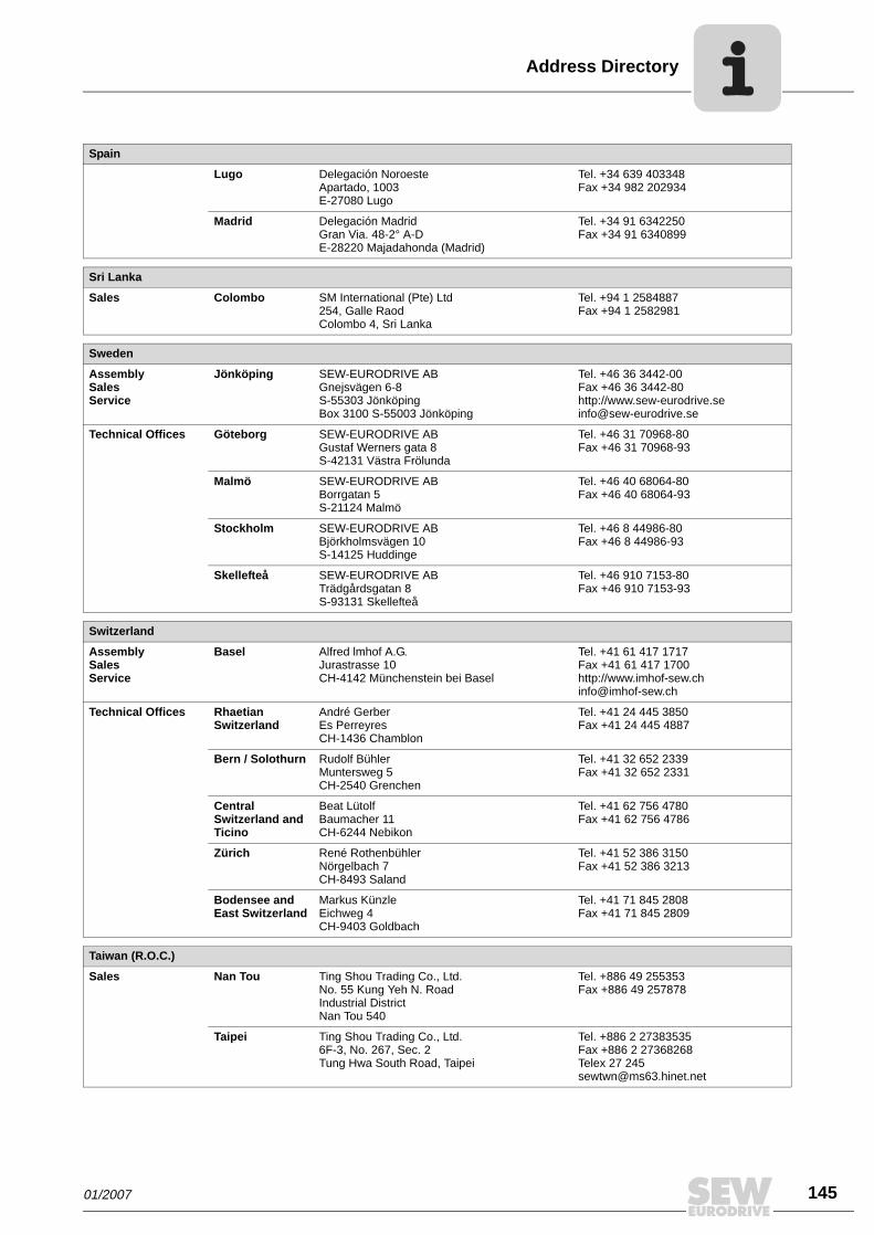
Address Directory
Lugo Delegación NoroesteApartado, 1003E-27080 Lugo
Tel. +34 639 403348Fax +34 982 202934
Madrid Delegación MadridGran Via. 48-2° A-D E-28220 Majadahonda (Madrid)
Tel. +34 91 6342250Fax +34 91 6340899
Sri Lanka
Sales Colombo SM International (Pte) Ltd254, Galle Raod Colombo 4, Sri Lanka
Tel. +94 1 2584887Fax +94 1 2582981
Sweden
AssemblySalesService
Jönköping SEW-EURODRIVE ABGnejsvägen 6-8S-55303 JönköpingBox 3100 S-55003 Jönköping
Tel. +46 36 3442-00Fax +46 36 3442-80http://[email protected]
Technical Offices Göteborg SEW-EURODRIVE ABGustaf Werners gata 8 S-42131 Västra Frölunda
Tel. +46 31 70968-80Fax +46 31 70968-93
Malmö SEW-EURODRIVE AB Borrgatan 5S-21124 Malmö
Tel. +46 40 68064-80Fax +46 40 68064-93
Stockholm SEW-EURODRIVE AB Björkholmsvägen 10 S-14125 Huddinge
Tel. +46 8 44986-80Fax +46 8 44986-93
Skellefteå SEW-EURODRIVE AB Trädgårdsgatan 8S-93131 Skellefteå
Tel. +46 910 7153-80Fax +46 910 7153-93
Switzerland
AssemblySalesService
Basel Alfred lmhof A.G.Jurastrasse 10 CH-4142 Münchenstein bei Basel
Tel. +41 61 417 1717Fax +41 61 417 1700http://[email protected]
Technical Offices Rhaetian Switzerland
André Gerber Es PerreyresCH-1436 Chamblon
Tel. +41 24 445 3850Fax +41 24 445 4887
Bern / Solothurn Rudolf BühlerMuntersweg 5CH-2540 Grenchen
Tel. +41 32 652 2339Fax +41 32 652 2331
Central Switzerland and Ticino
Beat Lütolf Baumacher 11CH-6244 Nebikon
Tel. +41 62 756 4780Fax +41 62 756 4786
Zürich René RothenbühlerNörgelbach 7CH-8493 Saland
Tel. +41 52 386 3150Fax +41 52 386 3213
Bodensee and East Switzerland
Markus KünzleEichweg 4CH-9403 Goldbach
Tel. +41 71 845 2808Fax +41 71 845 2809
Taiwan (R.O.C.)
Sales Nan Tou Ting Shou Trading Co., Ltd.No. 55 Kung Yeh N. RoadIndustrial DistrictNan Tou 540
Tel. +886 49 255353Fax +886 49 257878
Taipei Ting Shou Trading Co., Ltd. 6F-3, No. 267, Sec. 2 Tung Hwa South Road, Taipei
Tel. +886 2 27383535 Fax +886 2 27368268Telex 27 [email protected]
Spain
01/2007
145
146
ddress Directory
Thailand
AssemblySalesService
Chonburi SEW-EURODRIVE (Thailand) Ltd.700/456, Moo.7, DonhuarohMuang Chonburi 20000
Tel. +66 38 454281Fax +66 38 [email protected]
Technical Offices Bangkok SEW-EURODRIVE PTE LTDBangkok Liaison Office 6th floor, TPS Building1023, Phattanakarn RoadKlongtan, Phrakanong, Bangkok,10110
Tel. +66 2 7178149Fax +66 2 [email protected]
Hadyai SEW-EURODRIVE (Thailand) Ltd.Hadyai Country Home Condominium59/101 Soi.17/1Rachas-Utid Road. Hadyai, Songkhla 90110
Tel. +66 74 359441Fax +66 74 [email protected]
Khonkaen SEW-EURODRIVE (Thailand) Ltd.4th Floor, Kaow-U-HA MOTOR Bldg,359/2, Mitraphab Road.Muang DistrictKhonkaen 40000
Tel. +66 43 225745Fax +66 43 [email protected]
Lampang SEW-EURODRIVE (Thailand) Ltd.264 Chatchai Road, sob-tuy,Muang, Lampang 52100
Tel. +66 54 310241Fax +66 54 [email protected]
Tunisia
Sales Tunis T. M.S. Technic Marketing Service5, Rue El Houdaibiah 1000 Tunis
Tel. +216 71 4340-64 + 71 4320-29Fax +216 71 [email protected]
Turkey
AssemblySalesService
Istanbul SEW-EURODRIVE Hareket Sistemleri San. ve Tic. Ltd. Sti. Bagdat Cad. Koruma Cikmazi No. 3 TR-34846 Maltepe ISTANBUL
Tel. +90 216 4419163 / 164 3838014/15Fax +90 216 3055867http://[email protected]
Technical Offices Ankara SEW-EURODRIVE Hareket Sistemleri San. ve Tic. Ltd. Sti.Özcelik Is Merkezi, 14. Sok, No. 4/42TR-06370 Ostim/Ankara
Tel. +90 312 3853390 / +90 312 3544715 / +90 312 3546109Fax +90 312 3853258
Bursa SEW-EURODRIVE Hareket Sistemleri San. ve Tic. Ltd. Sti.Besevler Küçük SanayiParkoop Parçacilar Sitesi 48. Sokak No. 47TR Nilüfer/Bursa
Tel. +90 224 443 4556Fax +90 224 443 4558
Izmir SEW-EURODRIVE Hareket Sistemleri San. ve Tic. Ltd. Sti. 1203/11 Sok. No. 4/613Hasan Atli Is MerkeziTR-35110 Yenisehir-Izmir
Tel. +90 232 4696264Fax +90 232 4336105
Ukraine
SalesService
Dnepropetrovsk SEW-EURODRIVEStr. Rabochaja 23-B, Office 40949008 Dnepropetrovsk
Tel. +380 56 370 3211Fax +380 56 372 2078http://[email protected]
Sales Kiev SEW-EURODRIVE GmbHS. Oleynika str. 2102068 Kiev
Tel. +380 44 503 95 77Fax +380 44 503 95 [email protected]
Uruguay
Sales Montevideo SEW-EURODRIVE Uruguay, S. A.German Barbato 1526CP 11200 Montevideo
Tel. +598 2 90181-89Fax +598 2 [email protected]
A
01/2007

Address Directory
USA
ProductionAssemblySalesService
Greenville SEW-EURODRIVE INC. 1295 Old Spartanburg Highway P.O. Box 518Lyman, S.C. 29365
Tel. +1 864 439-7537Fax Sales +1 864 439-7830Fax Manuf. +1 864 439-9948Fax Ass. +1 864 439-0566Telex 805 550 http://[email protected]
AssemblySalesService
San Francisco SEW-EURODRIVE INC. 30599 San Antonio St.Hayward, California 94544-7101
Tel. +1 510 487-3560Fax +1 510 [email protected]
Philadelphia/PA SEW-EURODRIVE INC. Pureland Ind. Complex 2107 High Hill Road, P.O. Box 481Bridgeport, New Jersey 08014
Tel. +1 856 467-2277Fax +1 856 [email protected]
Dayton SEW-EURODRIVE INC.2001 West Main Street Troy, Ohio 45373
Tel. +1 937 335-0036Fax +1 937 [email protected]
Dallas SEW-EURODRIVE INC.3950 Platinum Way Dallas, Texas 75237
Tel. +1 214 330-4824Fax +1 214 [email protected]
Additional addresses for service in the USA provided on request!
Venezuela
AssemblySalesService
Valencia SEW-EURODRIVE Venezuela S.A.Av. Norte Sur No. 3, Galpon 84-319Zona Industrial Municipal NorteValencia, Estado Carabobo
Tel. +58 241 832-9804Fax +58 241 838-6275http://[email protected]@cantv.net
01/2007
147
www.sew-eurodrive.com
How we’re driving the world
With people whothink fast anddevelop thefuture with you.
With a worldwide service network that isalways close at hand.
With drives and controlsthat automaticallyimprove your productivity.
With comprehensiveknowledge in virtuallyevery branch ofindustry today.
With uncompromisingquality that reduces thecost and complexity ofdaily operations.
With a global presencethat offers responsive and reliable solutions. Anywhere.
With innovativetechnology that solvestomorrow’s problemstoday.
With online informationand software updates,via the Internet, availablearound the clock.
Gearmotors \ Industrial Gear Units \ Drive Electronics \ Drive Automation \ Services
SEW-EURODRIVEDriving the world
SEW-EURODRIVE GmbH & Co KGP.O. Box 3023 · D-76642 Bruchsal / GermanyPhone +49 7251 75-0 · Fax +49 7251 [email protected]


