68
Servicing &Technology FEBRUARY, 1982 $2.25 Servicing excessive high voltage ew ension in electronics www.americanradiohistory.com
Servicing &Technology FEBRUARY, 1982 $2.25
Servicing excessive high voltage
ew ension in
electronics
www.americanradiohistory.com

Behold! The Sylvan 1, ECG ®
Master Replacement Guide, the most comprehensive publication of its kind used by the industry.
Inside you will find more than 170,000 industry part numbers cross referenced to over 2,500 ECG numbers, including most of the hard -to -find foreign parts that are plaguing more and more repairmen every day.
If the part number is illegible, there are also easy to use com- prehensive selection tables to help you identify and replace
egist: d trademark of Philips ECG, lie -
It's not the bible, but a lot of service technicians swear by it.
transistors and lint -u IC's I a application. You will find clear, concise descriptions and illustra- tions on each type from diodes to IC's with specifications, appli- cations and package dimensions.
What's more, you also have Philips ECG technical resources ready to help you with any ques- tions you might have regarding particular situations or applica- tions; and as always, all ECG parts you will receive come with the knowledge that they've met specifications which are equal to
and usually exceed those of the original parts and that they've been tested using stringent pro- cedures established by the U.S. Military.
To find out more, seek your nearest authorized Philips ECG distributor.
If you are not already a believer, one look at our catalog should convert you.
PhilipsECG A North American Philips Company
Circle (1) on Reply Card
www.americanradiohistory.com

ELGOTROflID Servchnology
Editorial, advertising and circulation cor- respondence should be addressed to: P.O. Box 12901, Overland Park, KS 66212-9981 (a suburb of Kansas City, MO); (913)888-4664.
EDITORIAL Bill Rhodes, Editorial Director Carl Babcoke, Consumer Servicing Consultant Rhonda Wickham, Managing Editor Tina Thorpe, Associate Editor
ART Dudley Rose, Art Director
CIRCULATION John C. Arnst, Director Evelyn Rogers, Manager Dee Manies, Reader Correspondent
ADMINISTRATION R. J. Hancock, President Cameron Bishop, Publisher
ADVERTISING Greg Garrison, National Sales Manager Jeanette Staley, Production Manager Mark Raduziner, Marketing Coordinator
Regional advertising sales offices listed near Advertisers' Index.
ABC Member, Audit Bureau
of Circulation
Member, American ABP Business Press
ELECTRONIC SERVICING & TECHNOLOGY (USPS 462-050) (with which is combined °F Reporter) is published monthly by Intertec Publishing Corp., P.O. Box 12901, 9221 Ouivira Road, Overland Park, KS 66212-9981. Second Class Postage paid at Shawnee Mission, KS 66201. Send Form 3579 to P.O. Box 12901, Overland Park, KS
66212-9981.
ELECTRONIC SERVICING & TECHNOLOGY is the "how-to" magazine of electronics. It is edited for electronic en- thusiasts who are interested in buying, building, installing and repairing home -entertainment electronic equipment (audio, video, microcomputers, electronic games, etc.).
Subscription prices to qualified subscribers: one $15, two years $26, three years $34 in the USA and its possessions. Foreign countries: one year $20, two years $30, three years $40. Single copy price $2.25; back copies $3.00. Adjustment necessitated by subscription termination to single copy rate. Allow 6 to 8 weeks delivery for change of address. Allow 6 to 8 weeks for new subscriptions.
PHOTOCOPY RIGHTS: Permission to photocopy for internal or personal use is granted by Intertec Publishing Corp. for libraries and other registered with Copyright Clearance Center (CCC), provided the base fee of $2 per copy of arti- cle is paid directly to CCC, 21 Congress St., Salem, MA 01970. Special requests should be addressed to Cameron Bishop, publisher. ISSN 0013-497X/81 $2
11. INTERTEC PUBLISHING CORP.
'1981 All rights reserved.
35 DIGITAL MULTIMETER
Easily the best. In terms of resolution and accuracy, the Model 135 is easily the best handheld DMM available at any price. It's the only handheld offering 41/2
digits. That gives it 10 times better resoultion than the best 31/2 -digit
DMM and provides 3 to 4 times more useable
accuracy. Resolution isn't all you get. You get an easy -to -use instrument that's rugged and reliable enough to live in the read world. You get Keithley packaging.
Its large, crisp LCD makes it easy to read. Rotary switches and a color -coded faceplate
make it easy to use. Once -a -year calibration and long battery life make it easy to own. Easy to buy at 5235.
Best m price, best in performance. There is a DMM designed specifically for your application in the Keithley line. Your Keithley distributor has instruments in stock for your convenience. Call today for complete information and a demonstration.
Sound Choice. New Model 128 Beeper DMM. Audible/visual indication on all 5 functions of this 31/2 -digit DMM lets you test faster, and the user adjustable threshold and special diode test function make it a sound choice. Unique features, 5139.
Bench Bargain. Model 176, Portable Bench DMM. Full 5 -function LCD 41/2 -digit bench DMM offers 0.05% basic DCV accuracy. Keithley ease of use features include range and function annunciators, 1000 hour battery life and optional line operation. A bargain at 5269.
KEITH LEY Keithley Instruments, Inc. 28775 Aurora Road/Cleveland, Ohio 44139/(216) 248-0400
Circle (2) on Reply Card
February 1982 Electronic Servicing & Technology 1
www.americanradiohistory.com

The how-to magazine of electronics...
Ete811101118
February 1982
Volume 2. No. 2
ELEÇTiiOfliÇ amw....w.M ....,.
In the past few years, video games and teaching aids have exploded into a billion - dollar industry. Featured on the cover is Bill Cosby, a spokesperson for Texas Instruments. See story on page 26. (Photo courtesy of Texas Instruments Inc.)
12
14
20
25
26
37
46
52
56
Stumbling blocks on the CET exam Check out your electronics knowledge with this sampling of typical CET exam questions.
Servicing excessive high voltage, Part 1
By Homer L. Davidson and Carl Babcoke High voltage must be suspected when a picture tube, flyback, tripler or horizontal -output transistor fails.
Programming games for business or pleasure By Walter Dean, Computer Concepts Corporation Data processing equipment can be used to pursue bandits across the screen, as well as organize your finances.
Consumer guide to portable audio These tips on quality, price, sound, portability, comfort, fit, adaptability and company reputation will help you choose a portable stereophone.
Games people play A menu of 60 video games and learning aids, from five different manufacturers, shows the variety of cartridges offered on the market today.
More light on optical -fiber systems Optical -fiber transmission systems have many advantages over wire cable systems.
How to repair electronic garage -door openers By Carl Babcoke, CET This case history describes the first attempt of a color TV technician to troubleshoot a garage -door opener.
Test Lab By Carl Babcoke, CET B&K-Precision 3020 sweep/function generator is featured.
Elmo Manufacturing-entering a race of giants By Joel A. Samberg A 57 -year -old photographic equipment company has come out with its own version of a videodisc player.
2 Electronic Servicing & Technology February 1982
www.americanradiohistory.com

Page 14
Page 25
44 44 44 44 44
ne f°rhffiChf9e x x x iY Y 5e_ e e 511
SPACE INVADERS' Game Program"
Page 26
DEPARTMENTS 4 Electronic Scanner
6 Association News
8 Symcure
11 Reader's Exchange
13 Calendar of Events
58 New Products
66 New Literature
February 1982 Electronic Servicing & Technology 3
www.americanradiohistory.com

ELECTRONIC SCANNER
Westinghouse defense experts call engineer shortage critical
National efforts to boost in- dustrial productivity and maintain technological superiority in in- dustry and defense could be hampered by a critical shortage of engineers.
The problem is particularly acute in the high technology defense sector of American in- dustry. Some experts in the field have labeled the technical man- power shortage "the Achilles heel of our national defense."
"The current shortage of engineers is evolving into a na- tional crisis," says Marvin E. Jones, director of human resources for Westinghouse Elec- tric Corporation's Defense and Electronic Systems Center in Baltimore. Westinghouse is a billion -dollar defense contractor specializing in advanced elec- tronics such as radar and elec- tronic countermeasures systems.
"There simply are not enough people entering the engineering field today to meet industry's demands," Jones noted. "The microelectronics revolution, the in- creasing threat of foreign competi- tion, and the development of other new technologies have brought about fundamental changes in society. But, our educational system has been unable to keep up with these sweeping changes. As a result, our universities are graduating only about 60,000 engineers with bachelor's degrees each year. That's well short of the technical manpower demands of industry."
Hilton suites sell out at drawing for space
The Electronic Industry Show Corporation has announced that space at the Electronic Distribu- tion Show and Conference is rapid- ly running out. EDS will be held
April 29 - May 1, at the New Orleans Hilton hotel.
For the first time in the EDS history, the full alotment of suites in the main headquarters hotel was assigned at the drawing for space. Conference rooms are also sold out, according to David L. Fisher, EDS executive vice president. Ad- ditional suites remain at the New Orleans Marriott and Interna- tional hotels, and these, too, are expected to be claimed quickly. A dwindling supply 8' x 10' and 10' x 10' exhibit booths is still available in the Hilton's two halls to accom- modate most, if not all, late ap- plicants for EDS.
Computer network design featured in course from ICS
A comprehensive, state-of-the- art foundation in computer com- munication network concepts, technology and implementation, is provided in a course offered this spring and summer by Integrated Computer Systems (ICS).
The 4 -day course, entitled "Com- puter Network Design and Pro- tocols," emphasizes the practical aspects of network design, inter- facing, protocols and packet switching.
Priced at $845, the course will be held in Boston, April 13-16; Minneapolis, May 4-7; Los Angeles, May 18-21; Washington, D.C., June 15-18; San Francisco, July 13-16; and Boston, July 20-23.
For further information, contact Ruth Dordick, Integrated Com- puter Systems, 3304 Pico Blvd., P.O. Box 5339, Santa Monica, CA 90405; 213-450-2060.
Sony serviceability scores 94.09%
Changes in chassis design, quick access to components, and many snap -in parts all contributed to Sony's rating of excellent on a re- cent serviceability inspection of Sony model KV -1946R 19" color television, using the SCC342A chassis. The inspection was con- ducted for the International Socie- ty of Certified Electronics Techni- cians by a team headed by Dean Mock, CET, chairman.
The 94.09% total is the highest
rating, to this date, of any previously evaluated chassis from any manufacturer. Sony scored 1100.8 points out of a possible 1170.
The inspection was conducted at the Sony Corporation in Long Island City, NY.
Sony was commended for using common snap -in fuses and snap -on shields and for a clean and unclut- tered circuit board with excellent roadmapping and grouping. The mounting position of the chassis for easy access also received positive comments.
The chassis incorporated a number of changes that were recommended in a 1980 inspection conducted on another Sony model. Serviceability is an industry effort to make electronic servicing easier and more efficient.
Serviceability Inspections were held during 1981 by RCA, General Electric and Sony. Other manufac- turers interested in conducting in- spections should contact ISCET, 2708 West Berry, Fort Worth, TX 76109, 1-817-921-9101.
Pace Inc. announces new training program
Pace Inc. has announced the in- troduction of a complete 8 -part training program in "Rework and Repair for Electronics."
According to Bill Siegel, presi- dent of Pace Inc., this is one of the most comprehensive training pro- grams ever undertaken and can result in saving companies hun- dreds of thousands of dollars in costly repair, plus reduce critical downtime.
"We believe that everyone in- volved in electronics manufacture and maintenance should be trained in high reliability rework and repair," Siegel said.
"Few people are trained in repair for electronics and it's a lot more sophisticated than most peo- ple imagine. An unskilled person can cause more damage in trying to repair a PCB than was already there."
It is practically impossible to see how someone repairs a PCB because of the tiny point of action, so Pace has used the dynamics of
4 Electronic Servicing & Technology February 1982
www.americanradiohistory.com

TEK 2200 SERIES DUAL TRACE OSCILLOSCOPES
THE PERFORMANCE/ PRICE STANDARD
Ti?Jctronix 2213 a..,,.
The $1100 scope. Only Tektronix could make so much
performance so affordable! The 60 MHz Tek 2213 and 2215 introduce a scope design so radically different, it delivers full - range performance at prices well below what was ever possible before.
Not surprisingly, it is from Tektronix, the world's largest and most respected scope manufacturer, and a legend for instrument relia- bility and value.
Design for the 2213 ($1100) and dual time base 2215 (just $1400) includes some 65% fewer mechan- ical parts. Fewer circuit boards. Fewer electrical connectors and cabling. Result: a lower purchase price for you plus far greater reliability.
Performance is pure Tektronix: there's the
bandwidth for digital and high-speed analog circuits. The sensitivity for low signal measurements. The sweep speeds for fast logic families A complete trigger system for digital. analog or video waveforms. And, with the 2215, you get fully cali- brated delayed sweep for fast accurate timing meas- urements. New high- performance 10X Tektronix probes are included!
2213/2215 PERFORMANCE DATA
Bandwidth: Two channels. do -60 MHz from 10 V/div to 20 mV/div. (50 MHz from 2 mV/div to 10 mV/div).
Sweep speeds: Sweeps from 0.5 s to 50 ns (to 5 ns div with X10 mag).
Sensitivity: Scale factors from 100 V div (10X probe)
to 2 mV/div (1X probe). Ac- curate to ± 3%. Ac or dc coupling. Delayed sweep meas- urements: 2213: standard sweep, intensified after delay. and delayed. 2215: A only, B only, or A and B alternately with A intensified by B.
Complete trigger system: Modes include TV field, normal. vertical mode, and automatic; internal, exter- nal, and line sources; vari- able holdoff; separate B sweep trigger on 2215.
Probes: High perform- ance, positive attachment ,
10-14 pF and 60 MHz at the probe tip.
The price: Just $1100 for the 2213 and $1400 for the dual time base 2215*. Order direct from the
'Paces FOB Beaverton OR
Tektronix National Market- ing Center, your hotline for the 2200 Series and all Tektronix accessories. Phones are staffed by sales engineers who can answer your technical questions.
Your direct order includes a 15 -day return policy and full Tektronix warranty. Call today. You can't buy a more advanced scope for less.
ORDER TOLL FREE
800-547-1845 Ask for Department 905 (In Oregon, Alaska and Hawaii: 1-503-627-4502 col- lect.) Lines are open from 8 am EST to 5 pm PST.
Téktronix :OMMITTED TO E%CELLENCE
Copynght .'c> 1982 Tektronix Inc All nghts reserved 120 February 1982 Electronic Servicing & Technology 5
www.americanradiohistory.com

motion pictures that feature animation, cutaways and bigger - than life graphics to give students a hands-on feel for the repair pro- cess.
The 8 -part series is available on 16mm, Super 8, or video. The series includes concepts of repair, elements of construction, compo- nent removal, solder extraction, removing conformal coatings, repair of damaged PCBs, refur- bishing and replating edge connec- tors and preventing electrical damage to sensitive components. It also includes student hand- books and an instructor's guide with information on how to customize the presentation if desired.
Preview copies of Rework and Repair for Electronics are available to people with training responsibilities. Contact: Pace Training, 9893 Brewers Court, Laurel, MD 20707, 1-301-490- 9860.
ERA and NSCA to host seminars for sound and electronic installers
The New York chapter of the Electronic Representatives Association (ERA) and the Na- tional Sound Contractors Associa- tion (NSCA) will host a series of technical and marketing seminars on emerging markets for sound and electronic installers on March 30-31, 1982, at the Marriott La Guardia, Flushing, NY.
Sponsored by both organiza- tions, the seminar will deal with how the installer can get involved profitably in major emerging markets. Technical updates, in- dustry trends and marketing techniques will be covered by ex- perts drawn from various segments of the industry.
For further information, contact Joel Schwartz, L -C -A Sales Com- pany, 76 Main Street, Tuckahoe, NY 10707; 914-961-4700- or 212- 585-1645.
Sensors & Systems '82 conferences presented
A series of 3 -day conferences and exhibitions will be held in the western and central regions of the
United States in May/June 1982. The events will cover all aspects of sensor technology from temperature sensors to displace- ment, velocity, acceleration, force, pressure, temperature, light, radiation, magnetic field, moisture and chemical vapors, as well as signal conditioning, digital inter- faces and system interfaces.
For more information, contact Network Exhibitions, 785 Harriet Ave., Campbell, CA 95008; 408- 370-1661.
NATESA urges action on copyright bill
The National Association of Television & Electronic Servicers of America (NATE SA), through an appeal by Sony Corporation, is attempting to overturn bill S.1758. The order, which bans all record- ing of copyrighted video material, runs contrary to current recogni- tion on personal recording of copyrighted audio material, ac- cording to NATE SA.
The organization is urging con- cerned persons to write to Senators Dennis DiConcini of Arizona and Alphonse D'Amato of New York, sponsors of the bill, and senators from their own states.
Club and magazine launched for Odyssey2 players
Behind -the -scenes information, tips from the experts, new product previews and the opportunity to officially register high scores for free prizes can all be found in Odyssey2 Adventure, a new quarterly magazine for Odyssey2 video garners.
"As the official publication of the Odyssey2 Adventure Club," said Gerald A. Michaelson, vice presi- dent sales, special markets, "it will keep Odyssey2 owners abreast of the latest developments involving their computer home video game."
The Odyssey2 Adventure Club membership certificate and the club membership card will be enclosed with the March 1982 issue of Odyssey2 Adventure.
ASSOCIATION NEWS
NEDA presents symposium at EOS '82
The first annual Test and Measurement Distribution Con- ference will be a highlight of the National Electronic Distributors Association (NEDA) Management Conference, April 28, 1982, the day before the Electronic Distribu- tion Show opens at the New Orleans Hilton Hotel.
At the keynote luncheon, Thomas Kurlak, vice president - technology, Merrill Lynch Pierce Fenner and Smith, will discuss "Electronic distribution - the view from Wall Street".
A second concurrent afternoon Symposium will begin after the keynote luncheon on "Oppor- tunities in semiconductor distribu- tion". Paul Carroll, president, Semiconductor Specialists Inc., will serve as chairman of this meeting.
In addition to the two sym- posiums on April 28th, NEDA also has scheduled a variety of EDS '82 educational programs to be held each morning of the show. Two seminars will be repeated April 30 during show hours.
The NEDA Management Con- ference brochure may be obtained by writing the National Electronic Distributors Association, 1480 Renaissance Drive, Suite 214, Park Ridge, IL 60068, or phoning 1-312-298-9747.
National Sound and Electronic Systems Conference program announced
Plans for the third National Sound and Electronic Systems Conference, the sound contracting industry's forum for the exchange of ideas and information, has been announced by Robert F. Ancha, president of the National Sound and Communications Association. The NSCA-sponsored conference will be held April 29-May 1, at the
6 Electronic Servicing & Technology February 1982
www.americanradiohistory.com

"Fast and accurate readings. That's why we use the AWS EZ-Meter DMMs:" "At ITS, we maintain and service hundreds of pieces of computer equipment used by over 200 airline companies throughout the world. If even one piece of equipment goes down, serious back-up problems can occur. So our job is not only to make the proper repairs, but to make them fast. That's why we use the AWS EZ-Meter series of Digital Multi -Meters. With their Autoranging fea- ture (volts & ohms) we can count on quick, accurate readings hundreds of times a day - both on the bench and in the field. And with their Five -Year warranty, we think they're the best hand-held DMMs you can buy."
Other outstanding features include: Autoranging and full manual mode
(Models EZ -6100 & 6110) Audible continuity tone with 5 settings
(Models EZ -6100 & 6110) Nominal DC volt accuracy 0.5% of
reading (Models EZ -6100 & 6110) Zero adjust feather -touch button Low and normal power Ohm ranges 300 hours minimum continus opera-
tion with two 1.5V "AA" batteries 31/2 digit LCD indicates the function,
reading and feature simultaneously Exclusive FIVE-YEAR Warranty!
Circle (3) on Reply Card
Bob Murray. ITS Equipment & Leasing Corp.
For more information on the EZ-Meter series or any of the other fine AWS instruments call your local distributor or contact A.W. Sperry Instruments Inc., 245 Marcus Blvd., Hauppauge, N.Y. 11788
800-645-5398 Toll -Free (N. Y., Hawaii, Alaska call collect 516-231-7050).
A.W. SPERRY INSTRUMENTS INC. The Measurable Advantage.
New Orleans Marriott hotel. It combines management and technical sessions with an inten- sive program covering new markets for the sound and elec- tronic systems contractor.
In addition, the conference again offers the benefit of being concur- rent with the Electronic Distribu- tion Show and Conference, where a healthy percentage of the ex- hibits are of direct interest to sound and electronics systems con- tractors.
Information about the National Sound and Electronic Systems Conference is available from the National Sound and Com- munications Association, 5105 Tollview Drive, Rolling Meadows, IL 60008,1-312-577-8360.
NATESA study offers solutions to service problems
The National Association of Television & Electronic Servicers of America's (NATESA) study of problems that afflict all servicers
and add to the cost and frustra- tions of set owners, servicers and set producer/marketers, has revealed several simple solutions.
(1) Costly multiplicity of forms required by warrantors to authen- ticate compensation claims could be better served if each company authorized use of the NATE SA Service Order form.
(2) Parts procurement policies and procedures by various com- panies often cause serious delays in completing service and add to costs and time delays to servicers and set owners. The study in- dicates that installing toll -free phone numbers can eliminate misunderstandings.
(3) Service problem, back-up toll -free numbers can reduce cost of service to purchasers of your brand and servicers, resulting in better acceptance for your prod- ucts.
Coming in the March
K90111101118
Microprocessor...revolutionizing electronics. A look at some of the most elementary concepts in microprocessor operations explains this development in electronics.
How to choose the right interac- tive video equipment. With the movement of computers out of the expensive, elitist category, interactive video has become a popular way to present material.
Servicing excessive high voltage, part 2. Operation and ser- vicing of high -voltage regulators in solid-state color TV receivers are ex- plained.
February 1982 Electronic Servicing & Technology 7
www.americanradiohistory.com

Symptoms and cures compiled from field reports of recurring troubles. (The captions for the December 1981 symcure schematics were incorrectly placed. This is the corrected version.)
L
L
Chassis-Zenith 19FC45 PHOTOFACT -1466-3
r. i Il Il
I I 9-103 AUDIO II ° I L Ij C206 .0068
IiiN ERRATICALLY
OPEN
Symptom-Intermittent noise in sound, heard at all volume levels Cure-Check capacitor C206, and replace it if open
1 i Chassis-Zenith 20CC50z PHOTOFACT- 1238-3
Chassis -Zenith 19BG1z (monochrome) 3 PHOTOFACT -1692-2
VIDEO
Q803 VIDEO AMP
VIDEO
TO CRT
B+
VERT
BLANKING
Symptom-Retrace lines in a low -contrast picture Cure-Check video -output transistor 0803, and replace it if open
Chassis-Zenith Space Command with Zoom 5 PHOTOFACT - many
TO FRONT PANEL
ZOOM LIGHT
TO 9-92 VERTICAL MODULE 103-254 82K
PIN U18
- --= SHORTED
II II
W15 I I1X 9-126
+134V- ZOOM
Symptom-Insufficient vertical height in non -Zoom operation Cure-Check diode shown here, and replace it if shorted
Y
i
3.58 MHz AMP
Q8
L37
R220
1800 C163 .05
- INTERMITTENTLY +24 V OPEN
Symptom-Vertical color stripes appear erratically Cure-Check capacitor C163, and replace it if intermittently open
2
Chassis-Zenith 20CC50z 4 PHOTOFACT -1238-3
L28
FROM
T5
PIN 7
L29
6DN3 C123 1
810 DAMPER 880 V
BOOST
+390
SHORTED
Symptom- Loss of HV; horizontal -output plate glows red Cure- Check capacitor C123, and replace it if shorted
Chassis-Zenith 25DC57 6 PHOTOFACT -1315-3
+128 V
SUPPLY
Symptom - Loss of raster; regulator transistor overheats Cure-Check 22W dropping resistor R336, and replace it if open
J
8 Electronic Servicing & Technology February 1982
www.americanradiohistory.com

READERS' EXCHANGE
Needed: Sencore Mighty Mite VII tube tester model TC162. State condition and price. Cal 1-512-968-3913 or write Max Emerson, Rt. 2, Box 345, Weslaco, TX 78596.
Needed: Instruction manual for Electronics Measurement Corporation model #215 tube and transistor tester. R. L. Brown, Enterprises Unlimited, P.O. Box 1244, Carson City, NV 89701.
Needed: Service schematic for Magnavox model 10S150D b&w solid state TV set, serial #86249, chassis #U91507. Will buy, pay for copy or copy and return. Mrs. Magdalene Tyler Ramos, P.O. Box 214 Hub Sta., Bronx, NY 10455-0214.
Needed: BEAM -A -SCOPE SW band loop antenna (external plug in) for GE radio, model 260. J. F. Perry, Box 488, Lewisporte, N, f ld., Canada AOG 3A0.
Needed: Sam's Photofact folders 1536 through 1927, all or part, in sequence. Also sales and service literature and test equipment items from the early days of radio for a museum display. Bill Springer, 923 Nelda, Houston, TX 77088.
Needed: A 50lJA meter with a 41/2 -inch square case to replace a bad one in an old Ideal Instrument VOM that came with an RCA Radio Course. Donald Cole- man, 231 Kershaw Court, Joppa, MD 21085.
Needed: Schematic for a PRB custom hi-fi receiver, model 8TPR-888P. Robert Alvarez, 424 Denver, San Antonio, TX 78210.
Needed: Three #51 and two #45 tubes. Will pay a reasonable price. Gus A. Green, 12692 Green St., Boron, CA 93516.
Needed: Manual and schematic for a Paco model G-30 RF signal generator. Will buy or copy and return. Krist Pirovsky, 211 Rose Ellen Drive, Crown Point, IN 46307.
Needed: Any leaflets, brochures, handouts, etc. that would help me learn more about radio, audio and video technology. Ebby K. Joseph, "Ramalyan", Ped- der Rd., Cumballa Hill P.O., Bombay 400 026, India.
For Sale: Sencore TC 162 tube tester, $100; Sen - core handy "75" substituter, $40; Mark IVCUV 'tuner subber, $45. Robert Garrett, 1259 Carl St., Alton, IL 6200,2, 1-618-465-8950.
For Sale: B&K model 1460 oscilloscope in excellent working condition, $375. Tim Allen, Douglas Televi- sion Service, 2540 Trenainsville Rd., Toledo, OH 43613, 1-419-475-9322.
For Sale: Sencore VA48, like new, best offer over $600. Also a TF46 Super Cricket, best offer over $100. Mike Shepherd, 394 E. Hwy. 20, Republic WA 99166, 1-509-775-3035.
For Sale: Radio Shack-TRS-80 microcomputer, model 1, level II, 16K, including 32K expansion in- terface and RS 232C board. Shipping prepaid, $1460.00. Also a Macrotronics-TM-800 ham inter- face for TRS-80 microcomputer. Includes M-80 (ver- sion 2), M-800 module, FSD-1 and AFSK. Factory assembled and tested in original packing, $350.00. Also RCA master voltomist type 510A, $150.00, shipping prepaid. William Shevtchuk, Clifton, NJ. Please call: 201-471-3798.
!For Sale: B&K 415 generator; B&K CR143 CRT tester, B&K 1076 analyst. Best offer. Reiney's TV, 4733 Lewis Drive, Port Arthur, TX 77640.
Jim Ishee ofkhe Jim Ishee TV Clinic
Decatur, Illinois.
For 14 years Jim Ishee has relied on one
electronics remanufacturer. Like so many professional TV service dealers, Jim Ishee knows the impor- tance of fast, quality ser- vice. That's why, year after year, he's turned to PTS for quality remanufac- tured tuners and modules. Because PTS puts quality service first, customers
like Jim Ishee keep coming back. There's one electronics remanufacturer you can depend on, year after year, for quality tuners and modules.
Only One.
^1 PTS CORPORATION
For the name of the PTS Distributor or Servicenter nearest you write PTS Corporation, P.O. Box 272, Bloomington, IN 47402
Circle (4) on Hepiy Card
February 1982 Electronic Servicing & Technoloo
www.americanradiohistory.com
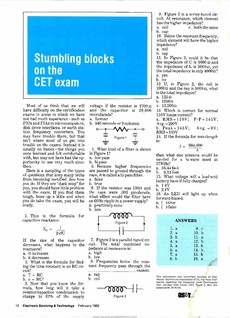
Stumbling blocks on the CET exam
Most of us think that we will have difficulty on the certification exams in areas in which we have not had much experience - such as PIOs and PIAs in microcomputers, disk drive interfaces, or earth sta- tion frequency converters. You may have trouble there, but that isn't where most of us get into trouble on the exams. Instead it is usually on basics - the things you once learned and felt comfortable with, but may not have had the op- portunity to use very much since then.
Here is a sampling of the types of questions that keep many techs from becoming certified. See how you do. If they are "duck soup" for you, you should have little problem with the exam. If you find them tough, bone up a little and when you do take the exam, you will be ready.
1. This is the formula for capacitive reactance:
Xc= 1
2TrfC
If the size of the capacitor decreases, what happens to the reactance? a. it increases b. it decreases
2. What is the formula for find- ing the time constant in an RC cir- cuit? a. T = RC b. e = MC2
3. Now that you know the for- mula, how long will it take a resistor/capacitor combination to charge to 67% of the supply
voltage if the resistor is 27001 and the capacitor is 20,000 microfarads? a. forever b. 54Q seconds or 9 minutes.
IFigure 1 T OM
4. What kind of a filter is shown in Figure 1? a. low pass b. hi pass
5. Because higher frequencies are passed to ground through the caps, it is called a hi -pass filter. a. false b. true
6. If the resistor was 10051 and the caps were .001 picofarads, what effect would the filter have on 60Hz ripple in a power supply? a. practically none b. lots
7. Figure 2 is a parallel -tuned cir- cuit. The total combined im- pedance at resonance is: a. high b. low
8. Frequencies below the reso- nant frequency pass through the
easiest. a. cap b. coil
lisör I I - Figure 3
9. Figure 3 is a series -tuned cir- cuit. At resonance, which element has the higher impedance? a. coil c. both the same b. cap 10. Below the resonant frequency, which element will have the higher impedance? a. coil b. cap 11. In Figure 3, could it be that the impedance of C is 1000 n and the impedance of L is 500051, yet the total impedance is only 400051? a. yes b. no 12. If, in Figure 2, the coil is 1000 n and the cap is 5000 n, what is the total impedance? a. 1255 b. 1250n c. 12,500n 13. Which is correct for normal 110V house current? a. RMS = 110V; P -P =145V; Avg. = 290V b. Peak= 145V; Avg. = OV; RMS =110V 14. If the formula for wavelength is:
f = 984,000 X
then what size antenna would be needed for a 1/4 -wave mast at 27MHz? a. 36.44 feet b. 9.11 feet 15. What voltage will a lead -acid battery have if fully charged? a. 1.4V b. 2.1V 16. An LED will light up when forward -biased. a. ( ) true b. ( ) false
ANSWERS
l.a 9.c 2. a 10. b 3. b 11. a 4. a 12. b 5. a 13. b 6. a 14. b 7. a 15. b 8. b 16. a
This information was submitted courtesy of Elec- tronics Technicians Association (ETA). For more infor- mation regarding the Associate Level Certification Test, contact Dick Glass, CET, R9yte 3, Box 564, Greencastle, IN 46135.
BM, 12 Electronic Servicing & Technology February 1982
www.americanradiohistory.com

CALENDAR OF EVENTS
February
2-4 Southcon '82, Orlando, FL, at
the Sheraton/Hyatt. For more in- formation call (800) 421-6816.
23-25 NEPCON WEST, Anaheim
Convention Center, Anaheim, CA. For more information, contact Cahners Exposition Group, 222 W. Adams St., Chicago, IL 60606, (312) 263-4866.
March
19-21 Computer Fair, Civic Audi-
torium, Brooks Hall, San Fran- cisco, CA. For more information call (415) 851-7075.
23-25 Southcon/82 Show and Conven-
tion, Sheraton Twin Towers Hotel, Orlando Hyatt Hotel and Holiday Inn International Drive, Orlando, FL. Call (800) 421-6816 for more information.
29 -May 1
1982 Electronic Distribution Show and Conference, New Orleans Hilton, New Orleans, LA. Contact David L. Fisher, Elec- tronic Industry Show Corp., 222 S. Riverside Plaza, Suite 1606, Chicago, IL 60606, (312) 648-1140.
April
14-18 Electronic Home Entertainment
Show, Arlington Park Race Track Exposition Hall, Chicago. Contact Expo Management Inc., Suite
S2-132 Arcade, The Apparel Center, Chicago, IL 60654, 1-312-329-1191.
23-25 Hamvention '82, Dayton Hara
Arena, Dayton, OH. For more in- formation call (513) 277-5314.
29 -May 1
Electronic Distribution Show, New Orleans Hilton, New Orleans, LA. For more information call (312) 648-1140.
May
10-12 The 32nd Electronic Com-
ponents Conference, Sheraton Harbor Island Hotel, San Diego, CA. Contact program chairperson D. J. Bendz, IBM Corp., Dept 649/014-4, 1701 North St., En- dicott, NY 13760.
11-15 National Association of Televi-
sion & Electronic Servicers of America (NATESA) 31st Annual Convention, Indian Lakes Resort, Bloomingdale, IL. Contact Frank J. Moch, 5930 S. Pulaski Rd., Chicago, IL 60629, 1-312-582- 6350.
18-20 Northcon/82 Show and Conven-
tion, Seattle Center Coliseum, Seattle, WA. Call (800) 421-6816 for more information.
25-27 Electro '82, Hynes Auditorium,
Boston, MA. For more informa- tion, call (800) 421-6816.
June
6-9 Summer CES '82, McCormick
Place, Chicago, IL. Contact Con- sumer Electronics Shows, Two Il- linois Center, Suite 1607, 233 North Michigan Avenue, Chicago, IL 60601, (312) 861-1040.
BM,
NOW, a mini -scope
with the features
most wanted by field
engineers!
UK -PRECISION MODEL 1420 $825
This new 15MHz dual -trace mini -scope was designed by B&K-PRECISION engineers to respond to the special needs of field engineers ... a mini -scope with lab -scope features.
It easily fits into a standard attache case with plenty of storage room for a DMM, tools and accessories. The 1420 can be powered from the AC line, 10-16VDC or an optional internal battery pack.
The rugged 1420 features dual -trace operation and an honest 15MHz re- sponse, with useful response beyond 20MHz. An efficient rectangular CRT displays waveforms with good read- ability under all field service conditions.
There is no sacrifice of features or performance for compact size. The 1420 has 18 sweep ranges from 1µS/div. to 0.5S/div. in a 1-2-5 sequence; variable between ranges. Sweep magnification is X10, extending the maximum sweep rate to 100nS/div. For use with computer terminals or video circuits, a video sync separator is built in. Automatic selection of chop and alternate sweep modes is provided, as is front -panel X -Y operation.
The Model 1420 measures only 4.5 X 8.5 X 12", weighs 7.75 lbs., with batteries and comes with two 10:1 probes.
FOR IMMEDIATE DELIVERY contact your local distributor or call TOLL - FREE, 800/621-4627 for a 16 -page catalog brochure on the complete B&K-PRECISION oscilloscope line.
+KPRfCISION
DYNASCAN CORPORATION
6460 West Cortland Street Chicago, Illinois 60635 312/889-9087
Intl. Sls 6460 w. Cortland St.. Chicago. IL 60635 Canadian Sales. Atlas Electronics, Ontario.
Circle (9) on Reply Card
February 1982 Electronic Servicing & Technology 13
www.americanradiohistory.com
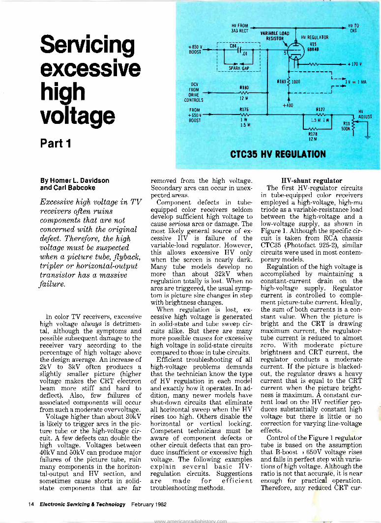
Servicing excessive high voltage Part 1
By Homer L. Davidson and Carl Babcoke
Excessive high voltage in TV receivers often ruins components that are not concerned with the original defect. Therefore, the high voltage must be suspected when a picture tube, flyback, tripler or horizontal -output transistor has a massive failure.
In color TV receivers, excessive high voltage always is detrimen- tal, although the symptoms and possible subsequent damage to the receiver vary according to the percentage of high voltage above the design average. An increase of 2kV to 3kV often produces a slightly smaller picture (higher voltage makes the CRT electron beam more stiff and hard to deflect). Also, few failures of associated components will occur from such a moderate overvoltage.
Voltage higher than about 30kV is likely to trigger arcs in the pic- ture tube or the high -voltage cir- cuit. A few defects can double the high voltage. Voltages between 40kV and 50kV can produce major failures of the picture tube, ruin many components in the horizon- tal -output and HV section, and sometimes cause shorts in solid- state components that are far
+850 V
BOOST
DCV
FROM
DRIVE
CONTROLS
FROM
+650 V
BOOST
HV FROM
3A3 RECT
C8a,
.0
SPARK GAP
R180
12 M
R176
1W 1.5 M
VARIABLE LOAD
RESISTOR
R181 1000
+400
HV REGULATOR
V15
6BK4B
HV TO
CRT
+170 V
1 L__
1V=1MA r- J
CTC35 HV REGULATION
removed from the high voltage. Secondary arcs can occur in unex- pected areas.
Component defects in tube - equipped color receivers seldom develop sufficient high voltage to cause serious arcs or damage. The most likely general source of ex- cessive HV is failure of the variable -load regulator. However, this allows excessive HV only when the screen is nearly dark. Many tube models develop no more than about 32kV when regulation totally is lost. When no arcs are triggered, the usual symp- tom is picture size changes in step with brightness changes.
When regulation is lost, ex- cessive high voltage is generated in solid-state and tube sweep cir- cuits alike. But there are many more possible causes for excessive high voltage in solid-state circuits compared to those in tube circuits.
Efficient troubleshooting of all high -voltage problems demands that the technician know the type of HV regulation in each model and exactly how it operates. In ad- dition, many newer models have shut -down circuits that eliminate all horizontal sweep when the HV rises too high. Others disable the horizontal or vertical locking. Competent technicians must be aware of component defects or other circuit defects that can pro- duce insufficient or excessive high voltage. The following examples explain several basic HV - regulation circuits. Suggestions are made for efficient troubleshooting methods.
HV
ADJUST
R11
500K
IEIV-shunt regulator The first HV -regulator circuits
in tube -equipped color receivers employed a high -voltage, high -mu triode as a variable -resistance load between the high -voltage and a low -voltage supply, as shown in Figure 1. Although the specific cir- cuit is taken from RCA chassis CTC35 (Photofact 925-2), similar circuits were used in most contem- porary models.
Regulation of the high voltage is accomplished by maintaining a constant -current drain on the high -voltage supply. Regulator current is controlled to comple- ment picture -tube current. Ideally, the sum of both currents is a con- stant value. When the picture is bright and the CRT is drawing maximum current, the regulator - tube current is reduced to almost zero. With moderate picture brightness and CRT current, the regulator conducts a moderate current. If the picture is blacked - out, the regulator draws a heavy current that is equal to the CRT current when the picture bright- ness is maximum. A constant cur- rent load on the HV rectifier pro- duces substantially constant high voltage but there is little or no correction for varying line -voltage effects.
Control of the Figure 1 regulator tube is based on the assumption that B -boost + 650V voltage rises and falls in perfect step with varia- tions of high voltage. Although the ratio is not that accurate, it is near enough for practical operation. Therefore, any reduced CRT cur -
14 Electronic Servicing & Technology February 1982
www.americanradiohistory.com
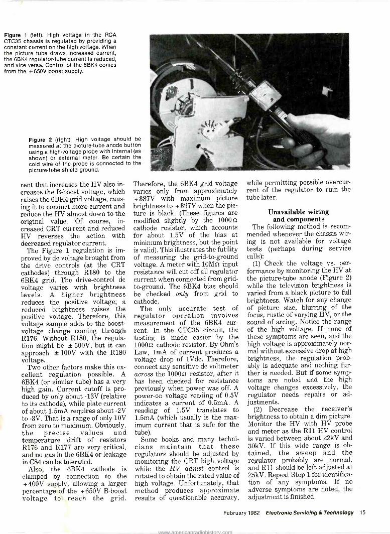
Figure 1 (left). High voltage in the RCA CTC35 chassis Is regulated by providing a constant current on the high voltage. When the picture tube draws increased current, the 6BK4 regulator -tube current is reduced, and vice versa. Control of the 6BK4 comes from the +650V boost supply.
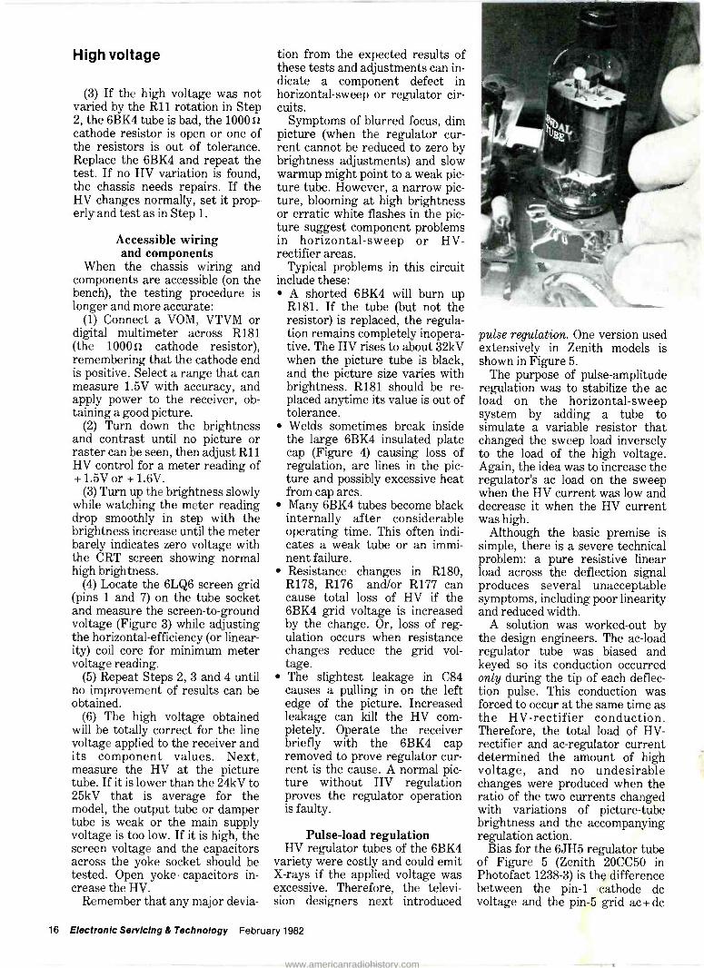
Figure 2 (right). High voltage should be measured at the picture -tube anode button using a high -voltage probe with internal (as
shown) or external meter. Be certain the cold wire of the probe is connected to the picture -tube shield ground.
rent that increases the HV also in- creases the B -boost voltage, which raises the 6BK4 grid voltage, caus- ing it to conduct more current and reduce the HV almost down to the original value. Of course, in- creased CRT current and reduced HV reverses the action with decreased regulator current.
The Figure 1 regulation is im- proved by do voltage brought from the (at the cathodes) through R180 to the 6BK4 grid. The drive -control do voltage varies with brightness levels. A higher brightness reduces the positive voltage; a reduced brightness raises the positive voltage. Therefore, this voltage sample adds to the boost - voltage change coming through R176. Without R180, the regula- tion might be ± 500V, but it can approach ± 100V with the R180 voltage.
Two other factors make this ex- cellent regulation possible. A 6BK4 (or similar tube) has a very high gain. Current cutoff is pro- duced by only about -13V (relative to its cathode), while plate current of about 1.5mA requires about -2V to -3V. That is a range of only 10V from zero to maximum. Obviously, the precise values and temperature drift of resistors R176 and R177 are very critical, and no gas in the 6BK4 or leakage in C84 can be tolerated.
Also, the 6BK4 cathode is clamped by connection to the + 400V supply, allowing a larger percentage of the + 650V B -boost voltage to reach the grid.
Therefore, the 6BK4 grid voltage varies only from approximately + 387V with maximum picture brightness to + 397V when the pic- ture is black. (These figures are modified slightly by the 10001-2
cathode resistor, which accounts for about 1.5V of the bias at minimum brightness, but the point is valid). This illustrates the futility of measuring the grid -to -ground voltage. A meter with 10Mo input resistance will cut off all regulator current when connected from grid - to -ground. The 6BK4 bias should be checked only from grid to cathode.
The only accurate test of regulator operation involves measurement of the 6BK4 cur- rent. In the CTC35 circuit, the testing is made easier by the 1000e cathode resistor. By Ohm's Law, 1mA of current produces a voltage drop of 1Vdc. Therefore, connect any sensitive do voltmeter across the 1000e resistor, after it has been checked for resistance previously when power was off. A power -on voltage reading of 0.5V indicates a current of 0.5mA. A reading of 1.5V translates to 1.5mA (which usually is the max- imum current that is safe for the tube).
Some books and many techni- cians maintain that these regulators should be adjusted by monitoring the CRT high voltage while the HV adjust control is rotated to obtain the rated value of high voltage. Unfortunately, that method produces approximate results of questionable accuracy,
while permitting possible overcur- rent of the regulator to ruin the tube later.
Unavailable wiring and components
The following method is recom- mended whenever the chassis wir- ing is not available for voltage tests (perhaps during service calls):
(1) Check the voltage vs. per- formance by monitoring the HV at the picture -tube anode (Figure 2) while the television brightness is varied from a black picture to full brightness. Watch for any change of picture size, blurring of the focus, rustle of varying HV, or the sound of arcing. Notice the range of the high voltage. If none of these symptoms are seen, and the high voltage is approximately nor- mal without excessive drop at high brightness, the regulation prob- ably is adequate and nothing fur- ther is needed. But if some symp- toms are noted and the high voltage changes excessively, the regulator needs repairs or ad- justments.
(2) Decrease the receiver's brightness to obtain a dim picture. Monitor the HV with HV probe and meter as the R11 HV control is varied between about 22kV and 30kV. If this wide range is ob- tained, the sweep and the regulator probably are normal, and R11 should be left adjusted at 25kV. Repeat Step 1 for identifica- tion of any symptoms. If no adverse symptoms are noted, the adjustment is finished.
February 1982 Electronic Servicing & Technology 15
www.americanradiohistory.com
High voltage
(3) If the high voltage was not varied by the R11 rotation in Step 2, the 6BK4 tube is bad, the 1000 as
cathode resistor is open or one of the resistors is out of tolerance. Replace the 6BK4 and repeat the test. If no HV variation is found, the chassis needs repairs. If the HV changes normally, set it prop- erly and test as in Step 1.
Accessible wiring and components
When the chassis wiring and components are accessible (on the bench), the testing procedure is longer and more accurate:
(1) Connect a VOM, VTVM or digital multimeter across R181 (the 100011 cathode resistor), remembering that the cathode end is positive. Select a range that can measure 1.5V with accuracy, and apply power to the receiver, ob- taining a good picture.
(2) Turn down the brightness and contrast until no picture or raster can be seen, then adjust R11 HV control for a meter reading of + 1.5V or + 1.6V.
(3) Turn up the brightness slowly while watching the meter reading drop smoothly in step with the brightness increase until the meter barely indicates zero voltage with the CRT screen showing normal high brightness.
(4) Locate the 6LQ6 screen grid (pins 1 and 7) on the tube socket and measure the screen -to -ground voltage (Figure 3) while adjusting the horizontal -efficiency (or linear- ity) coil core for minimum meter voltage reading.
(5) Repeat Steps 2, 3 and 4 until no improvement of results can be obtained.
(6) The high voltage obtained will be totally correct for the line voltage applied to the receiver and its component values. . Next, measure the 11V at the picture tube. If it is lower than the 24kV to 25kV that is average for the model, the output tube or damper tube is weak or the main supply voltage is too low. If it is high, the screen voltage and the capacitors across the yoke socket should be tested. Open yoke capacitors in- crease the 11V.
Remember that any major devia-
tion from the expected results of these tests and adjustments can in- dicate a component defect in horizontal -sweep or regulator cir- cuits.
Symptoms of blurred focus, dim picture (when the regulator cur- rent cannot be reduced to zero by brightness adjustments) and slow warmup might point to a weak pic- ture tube. However, a narrow pic- ture, blooming at high brightness or erratic white flashes in the pic- ture suggest component problems in horizontal -sweep or 11V - rectifier areas.
Typical problems in this circuit include these:
A shorted 6BK4 will burn up R181. If the tube (but not the resistor) is replaced, the regula- tion remains completely inopera- tive. The HV rises to about 32kV when the picture tube is black, and the picture size varies with brightness. R181 should be re- placed anytime its value is out of tolerance. Welds sometimes break inside the large 6BK4 insulated plate cap (Figure 4) causing loss of regulation, arc lines in the pic- ture possibly from cap arcs. Many 6BK4 tubes become black internally after considerable operating time. This often indi- cates a weak tube or an immi- nent failure. Resistance changes in R180, R178, R176 and/or R177 can cause total loss of HV if the 6BK4 grid voltage is increased by the change. Or, loss of reg- ulation occurs when resistance changes reduce the grid vol- tage. The slightest leakage in C84 causes a pulling in on the left edge of the picture. Increased leakage can kill the 11V com- pletely. Operate the receiver briefly with the 6BK4 cap removed to prove regulator cur- rent is the cause. A normal pic- ture without HV regulation proves the regulator operation is faulty.
Pulse -load regulation 11V regulator tubes of the 6BK4
variety were costly and could emit X-rays if the applied voltage was excessive. Therefore, the televi- sion designers next introduced
pulse regulation. One version used extensively in Zenith models is shown in Figure 5.
The purpose of pulse -amplitude regulation was to stabilize the ac load on the horizontal -sweep system by adding a tube to simulate a variable resistor that changed the sweep load inversely to the load of the high voltage. Again, the idea was to increase the regulator's ac load on the sweep when the 11V current was low and decrease it when the HV current was high.
Although the basic premise is simple, there is a severe technical problem: a pure resistive linear load across the deflection signal produces several unacceptable symptoms, including poor linearity and reduced width.
A solution was worked -out by the design engineers. The ac -load regulator tube was biased and keyed so its conduction occurred only during the tip of each deflec- tion pulse. This conduction was forced to occur at the same time as the HV -rectifier conduction. Therefore, the total load of HV - rectifier and ac -regulator current determined the amount of high voltage, and no undesirable changes were produced when the ratio of the two currents changed with variations of picture -tube brightness and the accompanying regulation action.
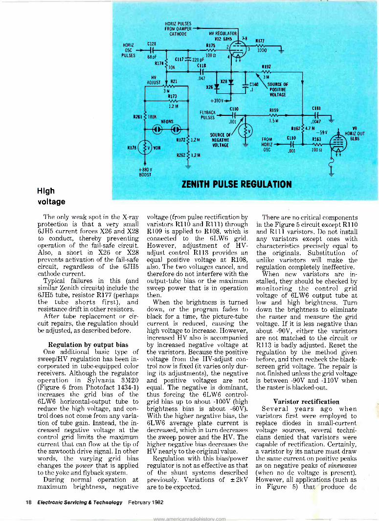
Bias for the 6JH5 regulator tube of Figure 5 (Zenith 20CC50 in Photofact 1238-3) is the difference between the pin -1 cathode do voltage and the pin -5 grid ac + dc
16 Electronic Servicing & Technology February 1982
www.americanradiohistory.com
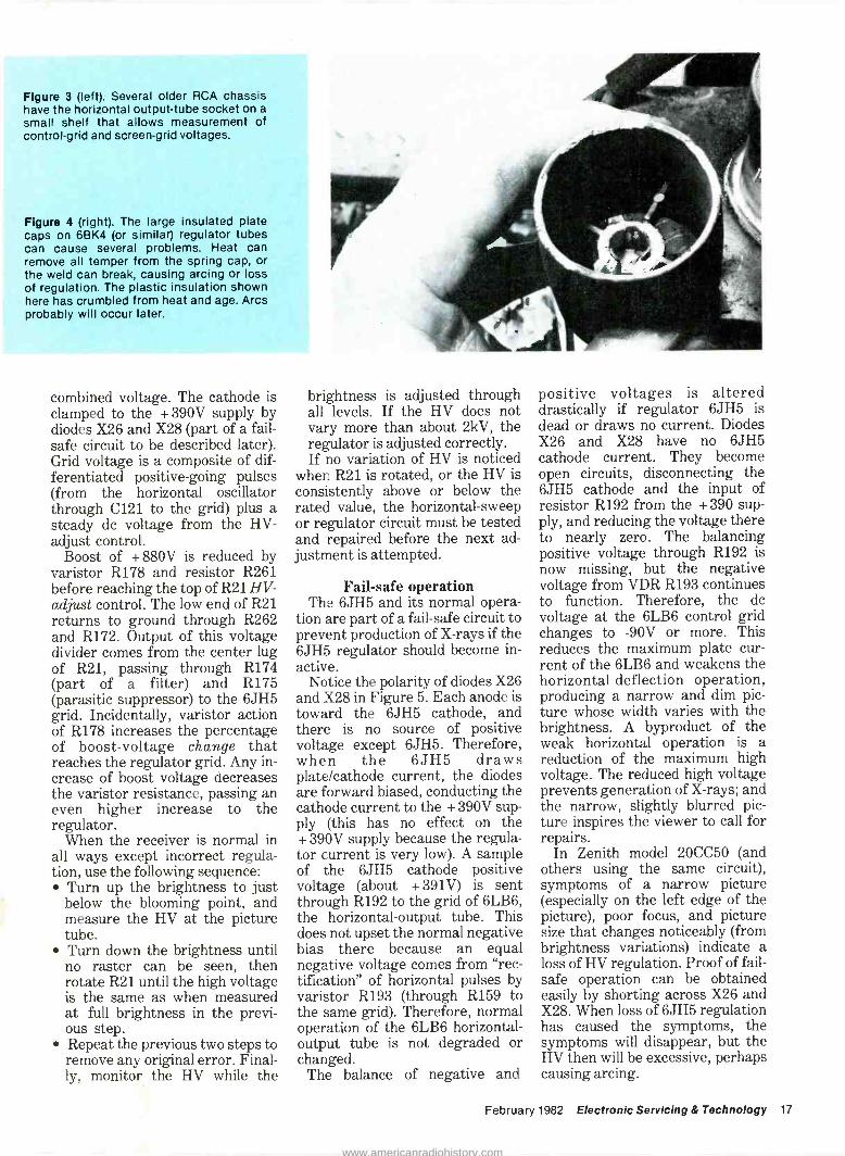
Figure 3 (left). Several older RCA chassis have the horizontal output -tube socket on a small shelf that allows measurement of control -grid and screen -grid voltages.
Figure 4 (right). The large insulated plate caps on 6BK4 (or similar) regulator tubes can cause several problems. Heat can remove all temper from the spring cap, or the weld can break, causing arcing or loss of regulation. The plastic insulation shown here has crumbled from heat and age. Arcs probably will occur later.
combined voltage. The cathode is clamped to the + 390V supply by diodes X26 and X28 (part of a fail- safe circuit to be described later). Grid voltage is a composite of dif- ferentiated positive -going pulses (from the horizontal oscillator through C121 to the grid) plus a steady do voltage from the HV - adjust control.
Boost of + 880V is reduced by varistor R178 and resistor R261 before reaching the top of R21 HV - adjust control. The low end of R21 returns to ground through R262 and R172. Output of this voltage divider comes from the center lug of R21, passing through R174 (part of a filter) and R175 (parasitic suppressor) to the 6JH5 grid. Incidentally, varistor action of R178 increases the percentage of boost -voltage change that reaches the regulator grid. Any in- crease of boost voltage decreases the varistor resistance, passing an even higher increase to the regulator.
When the receiver is normal in all ways except incorrect regula- tion, use the following sequence:
Turn up the brightness to just below the blooming point, and measure the HV at the picture tube. Turn down the brightness until no raster can be seen, then rotate R21 until the high voltage is the same as when measured at full brightness in the previ- ous step. Repeat the previous two steps to remove any original error. Final- ly, monitor the HV while the
brightness is adjusted through all levels. If the HV does not vary more than about 2kV, the regulator is adjusted correctly. If no variation of HV is noticed
when R21 is rotated, or the HV is consistently above or below the rated value, the horizontal -sweep or regulator circuit must be tested and repaired before the next ad- justment is attempted.
Fail-safe operation The 6JH5 and its normal opera-
tion are part of a fail-safe circuit to prevent production of X-rays if the 6JH5 regulator should become in- active.
Notice the polarity of diodes X26 and X28 in Figure 5. Each anode is toward the 6JH5 cathode, and there is no source of positive voltage except 6JH5. Therefore, when the 6JH5 draws plate/cathode current, the diodes are forward biased, conducting the cathode current to the + 390V sup- ply (this has no effect on the + 390V supply because the regula- tor current is very low). A sample of the 6JH5 cathode positive voltage (about + 391V) is sent through R192 to the grid of 6LB6, the horizontal -output tube. This does not upset the normal negative bias there because an equal negative voltage comes from "rec- tification" of horizontal pulses by varistor R193 (through R159 to the same grid). Therefore, normal operation of the 6LB6 horizontal - output tube is not degraded or changed.
The balance of negative and
positive voltages is altered drastically if regulator 6JH5 is dead or draws no current. Diodes X26 and X28 have no 6JH5 cathode current. They become open circuits, disconnecting the 6JH5 cathode and the input of resistor R192 from the +390 sup- ply, and reducing the voltage there to nearly zero. The balancing positive voltage through R192 is now missing, but the negative voltage from VDR R193 continues to function. Therefore, the do voltage at the 6LB6 control grid changes to -90V or more. This reduces the maximum plate cur- rent of the 6LB6 and weakens the horizontal -deflection operation, producing a narrow and dim pic- ture whose width varies with the brightness. A byproduct of the weak horizontal operation is a reduction of the maximum high voltage. The reduced high voltage prevents generation of X-rays; and the narrow, slightly blurred pic- ture inspires the viewer to call for repairs.
In Zenith model 20CC50 (and others using the same circuit), symptoms of a narrow picture (especially on the left edge of the picture), poor focus, and picture size that changes noticeably (from brightness variations) indicate a loss of HV regulation. Proof of fail- safe operation can be obtained easily by shorting across X26 and X28. When loss of 6JH5 regulation has caused the symptoms, the symptoms will disappear, but the HV then will be excessive, perhaps causing arcing.
February 1982 Electronic Servicing & Technology 17
www.americanradiohistory.com
High voltage
HORIZ C121
OSC
PULSES 68pF
R174
R261
R178
HV
ADJUST
HORIZ PULSES
FROM DAMPER
CATHODE
C111
10K
R21
1.2 M
180K
NEONS
+880 V
BOOST
VDR
HV REGULATOR
V12 6JH5 7-8
R175 2
100
T 220pF
C118
R172 SOURCE OF
1.2 M NEGATIVE
VOLTAGE
R262 1.2 M
I ( .047
X28 1 X26 V
+390Ví C110
FLYBACK i
PULSES .001
3
R177
1000
\
C140
T.1
R192
3M
SOURCE OF
POSITIVE
VOLTAGE
R159 C181
.0047
R162 4.7 M
-59V FROM C110 R163
HORIZ
OSC .001 100 n
1.5 M
ZENITH PULSE REGULATION
V9
HORIZ OUT
6LB6
The only weak spot in the X-ray protection is that a very small 6JH5 current forces X26 and X28 to conduct, thereby preventing operation of the fail-safe circuit. Also, a short in X26 or X28 prevents activation of the fail-safe circuit, regardless of the 6JH5 cathode current.
Typical failures in this (and similar Zenith circuits) include the 6JH5 tube, resistor R177 (perhaps the tube shorts first), and resistance drift in other resistors.
After tube replacement or cir- cuit repairs, the regulation should be adjusted, as described before.
Regulation by output bias One additional basic type of
sweep/HV regulation has been in- corporated in tube -equipped color receivers. Although the regulator operation in Sylvania 3M20 (Figure 6 from Photofact 1434-1) increases the grid bias of the 6LW6 horizontal -output tube to reduce the high voltage, and con- trol does not come from any varia- tion of tube gain. Instead, the in- creased negative voltage at the control grid limits the maximum current that can flow at the tip of the sawtooth drive signal. In other words, the varying grid bias changes the power that is applied to the yoke and flyback system.
During normal operation at maximum brightness, negative
voltage (from pulse rectification by varistors R110 and R111) through R109 is applied to R108, which is connected to the 6LW6 grid. However, adjustment of HV - adjust control R113 provides an equal positive voltage at R108, also. The two voltages cancel, and therefore do not interfere with the output -tube bias or the maximum sweep power that is in operation then.
When the brightness is turned down, or the program fades to black for a time, the picture -tube current is reduced, causing the high voltage to increase. However, increased HV also is accompanied by increased negative voltage at the varistors. Because the positive voltage from the HV -adjust con- trol now is fixed (it varies only dur- ing its adjustments), the negative and positive voltages are not equal. The negative is dominant, thus forcing the 6LW6 control - grid bias up to about -100V (high brightness bias is about -60V). With the higher negative bias, the 6LW6 average plate current is decreased, which in turn decreases the sweep power and the HV. The higher negative bias decreases the HV nearly to the original value.
Regulation with this bias/power regulator is not as effective as that of the shunt systems described previously. Variations of ± 2kV are to be expected.
There are no critical components in the Figure 5 circuit except R110 and R111 varistors. Do not install any varistors except ones with characteristics precisely equal to the originals. Substitution of unlike varistors will make the regulation completely ineffective.
When new varistors are in- stalled, they should be checked by monitoring the control grid voltage of 6LW6 output tube at low and high brightness. Turn down the brightness to eliminate the raster and measure the grid voltage. If it is less negative than about -90V, either the varistors are not matched to the circuit or R113 is badly adjusted. Reset the regulation by the method given before, and then recheck the black - screen grid voltage. The repair is not finished unless the grid voltage is between -90V and -110V when the raster is blacked -out.
Varistor rectification Several years ago when
varistors first were employed to replace diodes in small -current voltage sources, several techni- cians denied that varistors were capable of rectification. Certainly, a varistor by its nature must draw the same current on positive peaks as on negative peaks of sinewaves (when no do voltage is present). However, all applications (such as in Figure 5) that produce do
18 Electronic Servicing & Technology February 1982
www.americanradiohistory.com
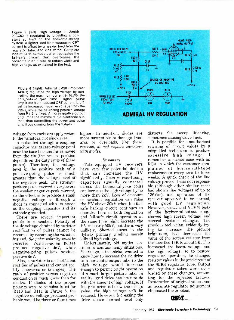
Figure 5 (left). High voltage in Zenith 20CC50 is regulated by providing a con- stant ac load on the horizontal -sweep system. A lighter load from decreased CRT current is offset by a heavier load from the regulator tube, and vice versa. Complete loss of 6JH5 cathode current activates the fail-safe circuit that overbiases the horizontal -output tube to reduce width and high voltage, as explained in the text.
Figure 6 (right). Admiral 3M20 (Photofact 1434-1) regulates the high voltage by con- trolling the maximum current in 6LW6, the horizontal -output tube. Higher pulse amplitude from reduced CRT current is off- set by increased negative voltage from the VDRs, while the balancing positive voltage from R113 is fixed. A more -negative output grid limits the maximum plate/cathode cur- rent, thus controlling the power and pulse amplitude coming from the flyback.
voltage from varistors apply pulses to the varistors, not sinewaves.
A pulse fed through a coupling capacitor has its zero -voltage point near the base line and far removed from the tip (the precise position depends on the duty cycle of these pulses). Therefore, the voltage level in the positive peak of a positive -going pulse is much greater than the voltage level of the negative peak. The stronger positive -peak current overpowers the weaker negative -peak current, so the effect is to produce a small negative voltage as through a diode is connected with its anode at the coupling capacitor and its cathode grounded.
There are several important points to remember. Polarity of the do voltage obtained by varistor rectification of pulses cannot be reversed by reversing the varistor; instead, the pulse polarity must be inverted. Positive -going pulses produce negative dcV, while negative -going pulses produce positive dcV.
Also, a varistor is an inefficient rectifier of pulses (and cannot rec- tify sinewaves or triangles). The ratio of positive versus negative conduction is much lower than for diodes. If diodes of the proper polarity were to be substituted for R110 and R111 in Figure 5, the negative do voltage produced pro- bably would be three or four times
HORIZ OSC DRIVE
FROM M800
PIN 1
RI13 5 M1t
HV
R112
R114 -105V
R108
180K
1.3M
12.2MI
R109 220K
+295V 2 VV
C106
HORIZ PULSES -0-if f FROM 1104 270 pF
FLYBACK N2200
100 u
C117
IF -1 .01
45
6LW6 V100
HORIZ OUTPUT
3
SOURCE OF NEGATIVE / DC VOLTAGE
R110
VDR
R111
O VDR
R1152330
R116
ADMIRAL HV REGULATION
2400 u 1W
+295V
higher. In addition, diodes are more susceptible to damage from arcs or overloads. For these reasons, do not replace varistors with diodes.
Summary Tube -equipped TV receivers
have very few potential defects that can increase the HV significantly. Open retrace -tuning capacitors (usually connected across the horizontal -yoke coils) can increase the high voltage by no more than 2kV. Loss of dc -shunt or ac -shunt regulation can raise the HV above 30kV when the fail- safe backup circuit continues to operate. Loss of both regulation and fail-safe circuit operation at the same time might increase the HV to nearly 50kV, but this is very unlikely. Shorted turns in the flyback primary winding merely kills all high voltage.
Unfortunately, old myths con- tinue to confuse many situations. Years ago, a technician wanted to know how to increase the rid drive to a horizontal -output tube so the high voltage would increase enough to permit bright operation of a much larger picture tube. In reality, grid drive has little to do with the amount of high voltage. If the grid drive is below the design value, the high voltage will be reduced. However, increasing the drive above normal level only
distorts the sweep linearity, sometimes causing drive lines.
It is possible for unauthorized rewiring of circuit values by a misguided technician to produce excessive high voltage. I remember a classic case with an RCA in which the customer com- plained of horizontal -tube replacements every two to three weeks. A quick check of the line voltage proved it was not responsi- ble (although other similar cases had shown line voltages of up to 136Vac), and operation of the receiver appeared to be normal, with good HV regulation. However, visual and VTVM tests of the horizontal -output stage showed high screen voltage and several resistor changes. The previous technician, evidently try- ing to increase the picture brightness, had decreased the value of the screen resistor from the specified 16K to about 3K. This increased the boost voltage and the high voltage, so to restore regulator operation, he changed resistor values in the grid circuit of the 6BK4 regulator tube. Output and regulator tubes were over- loaded by these changes, accoun- ting for the repeated failures. Restoration of original values and an accurate regulator adjustment eliminated the problem.
February 1982 Electronic Servicing & Technology 19
www.americanradiohistory.com
Programming games
for business or pleasure By Walter Dean, production manager,
Computer Concepts Corporation, Shawnee Mission, KS
Everybody knows that com- puters are expensive and should be treated with respect and decorum. But, behind the serious Dr. Jekyl facade of any business computer lurks a Mr. Hyde wanting to show everybody a good time.
You will likely find the data pro- cessing equipment in any facility used to pursue bandits across galaxies or to establish the resi- dent chess champion. Take, for ex- ample, a small laboratory in cen- tral Texas that conducts research on secret Navy projects. The elaborate apparatus normally used to process marine data also presents a fairly good game of Space War. The computer will ac- commodate several players, each with his own joystick control and CRT. Like most space war games, the object is to french fry your fellow players while simultaneous- ly staying in orbit around a star located in the center of the screen. The joysticks used in this game are surplus from actual fighter planes.
A company in the Midwest that manufactures radio navigation equipment for airplanes provides an even more subtle example. They make a color radar that uses several tiny computers - each one
only 3 inches long. It seems that the programming necessary to generate, analyze and display radar information on the color CRT does not entirely fill the allowable memory for these com- puters. Thus, the remaining room has been used to create a game similar to Space Invaders. The word is that this game is not available as an option once the unit is installed in the airplane.
Managers are reluctant to admit to what extent this "didactic pro- gramming" has displaced the in- tended purpose of their com- puters. In extreme cases, I've seen managers attempt to catch players by making subtle changes to the more popular game programs so a permanent record was made of the date, time and name of the person playing.
Widespread appeal Although playing a computer
game rarely accomplishes anything except to waste time and money, fun programs do have their place.
Computer Concepts Corporation is now realizing the appeal that a simple game of blackjack can add to a multi -thousand -dollar com-
puter package. I have actually seen a 9 kilobyte game sell a multi - terminal system and 5 man-years of software. This is something similar to a lighted vanity mirror selling a fleet of Cadillacs.
As a marketing strategy, Com- puter Concepts uses their favored games during idle hours at a con- vention. Salesmen who would otherwise be standing around in shoes they've worn three hours too long are suddenly interested in those cute things the program- mers have cooked up. It was dur- ing one of these intermissions that they discovered how a computer can even beckon prospects from the booths of competitors. Then the salesmen turn the controls over to the newcomer and move smoothly into a sales pitch.
Practical use of games (let's call it "applied gaming") has also spread to installers and service men. When a new computer is delivered to the proud customer, the installing technician will bring up a game with lots of display magic and sounds. The idea here is to help convince the staff that the computer is not the enemy out to get their job, but a friend instead. The video display terminal (VDT)
20 Electronic Servicing & Technology February 1982
www.americanradiohistory.com

has a lot of buttons, but a com- puter game can demonstrate that they are no more mysterious than those on a typewriter or an adding machine.
The service people at Computer Concepts use games as diagnostics. Sometimes, running a complex game that fills all available memory is a better sleuth than running a special diagnostic program for several hours.
It should come as no surprise that games have increased in sophistication over the years just as impressively as has the hard- ware itself (remember TV Pong?).
Static vs. dynamic In creating a game program, it is
sometimes useful to consider the possible categories now making the rounds. I have identified the following:
Games of Chance-blackjack and roulette Board Games - chess or Othello Adventure - Cave or Wumpus Space - Star Trek or Space Invaders Any of these games can be for-
matted to be either static or dynamic in nature. A static game is one that does nothing until the human enters data. After process- ing, the computer then generates a response and waits for more infor- mation. A dynamic game con- tinues to evolve even in the absence of human stimulus. The gremlins of Space Invaders, for example, will march relentlessly toward your missile launcher, bombing their way through any obstacle, regardless of the player's attention to the game. In most forms of chess or Star Trek, however, the player could take a two-week vacation between moves with no detriment to the game. Dynamic games were not very practical before the days of CRT terminals.
In a dynamic game, a display moves and changes according to the current conditions. In static games, the player is usually asked to pretend that pieces moved in a natural manner and accept their current status based on a series of coordinates.
Star Trek is the classic - the Monopoly of computer games. There is no telling how many peo-
ple became programmers because of their exposure to those early versions of this game.
Based loosely on the TV show, Star Trek usually involves "flying" the Starship Enterprise around the galaxy, phasing down Klingons and other undesireables. The computer -generated Enterprise is appointed with an array of gadgetry that must be kept ser- viceable in order to "go where no man has gone before." The game is further complicated by the natural hostility of Klingons and the recur- ring need to replenish the Enter- prise.
These early forms of Star Trek had a simple, nondynamic nature. The captain of the Enterprise would enter a number represent- ing a command and wait for the computer to tell him what had hap- pened. You saw nothing move because in the early days everybody had teletype machines. A lot of time was spent waiting for the updated map of the galaxy to be printed out at 110 BAUD. As with traditional board games, play progresses only as long as you enter commands (in more ad- vanced versions, though, a clock was kept running to terminate the game when the Enterprise had not been sufficiently zealous).
I have found that no matter how limited, any computer can be en- dowed with a challenging pro -
The idea is to convince the staff that the computer
is not their enemy.
gram. Programmers must be 4. respected for overcoming the fact that their computer was designed for business or science, and there- fore cannot easily be made to go 5.
"zap," "pow," or show explosions in Technicolor.
If you are interested in design- ing your own games, whether for business or pleasure, here are some random comments culled from my own experience.
Designing a game requires plan- ning in at least three areas:
1. Display-How is the game to be presented to the player(s)? The considerations for dis- playing a game on a printer device vs. a VDT usually dif- fer radically.
2. Algorithm - How does the game progress? In games where the computer repre- sents one of the opponents (in the case of Star Trek, the computer is playing for the Klingons), how are intelligent moves selected for the com- puter?
3. Modeling-How is the game to be represented internally to the computer? No matter how you might fantasize the interior of a castle or the shape of a pawn, the comput- er must be told the essen- tials of your vision only in numbers.
Display I have often been asked by
novice programmers how objects are made to move smoothly across the screen of a VDT. The truth is, a computer simulates motion in the exact way as does a movie pro- jector. That is, the object is displayed in constantly changing locations several times a second to give the object a smooth, natural movement. As you can see, this kind of effect would be impossible on a printing terminal, no matter how fast it might operate.
Here's a simple algorithm to il- lustrate this principle.
1. Select a starting place to print moving character
2. Print character 3. After a brief delay (long
enough for the eye to see the the character), erase the character. Select a new place to print the character. (If relocated too far away, the character will appear to jump). Return to Step 2.
February 1982 Electronic Servicing & Technology 21
www.americanradiohistory.com

Programming games
If you are programming in BASIC, the algorithm above might be implemented as follows:
10 REM INITIALIZE VARIABLES: R - 10: C = 40: T = 9
20 REM PRINT CHARACTER: PRINT AT (R,C); "X";
30 REM KILL A LITTLE TIME: FOR I = 1 TO 1000: NEXT I
40 REM ERASE CHARACTER: PRINT AT (R,C); " "
50 REM COMPUTE NEW LOCATION: R = R + SIN(T): C=C+2"COS(T):T=T+9
60 REM REPEAT: GOTO 20
When designing, show off the game
with some romance and use graphics
when possible.
When executed, the letter X will effortlessly glide around in a cir- cle. Naturally, the letter X could be replaced with any character or combination of characters. The delay loop on line 30 will need to be adjusted for the particular com- puter the code is executed on to compensate for varying clock speeds.
BASIC is adequate for most moving displays (especially on a WANG). However, the busier the game, the more strongly I recom- mend a compiled or an assembled language.
More tips on displays: 1. Show off the game with some
unnecessary romance. Don't just print an X or 0 in the appropriate location in tic tac toe, make them flash on and off a few times first, or grow in size until they fill up the entire square. Make the hanged man swing in the
breeze in hangman. 2. Use graphics when possible.
Playing chess is much easier with properly shaped pieces rather than with pieces rep- resented with letters K, Q, N and so on. When graphics are not available, use equals signs for laser beams, pound sym- bols for explosions, letters surrounded by "less than" and "greater than" symbols for targets and asterisks for stars.
3. Write your code so that the entire display can be re- printed with a single key- stroke. This will help you re- cover from accidents such as power failures to your VDT or failures in your program that you have to fix on the spot. With this feature, you can mend your code as neces- sary and merely press a but- ton to resume play.
4. Be efficient and use every position on a VDT to advan- tage. It helps to have all the necessary information on the screen at the same time in a game such as Star Trek.
Algorithms An algorithm can be thought of
as a set of instructions by which a desired goal may be met. Below is an algorithm for calling your mother on Mother's Day:
1. Obtain phone number. 2. Locate phone. 3. Dial number (this involves a
separate algorithm). 4. If it rings, go to Step 5.
Otherwise, some error might have occurred. If you want to keep trying the same num- ber, go to Step 3. Other- wise, return to Step 1.
5. If someone answers go to Step 6. If no answer, wait a while and return to Step 1.
6. Say "Hi," tell her you miss her and ask her to send down some of those oatmeal cook- ies she used to make when you were in college.
The task of identifying each step of any process is quite tricky. In my experience, a programmer almost never successfully thinks of them all before he starts writing code. The art of representing these
steps on paper is called "flow charting." Each programmer seems to have his favorite tech- niques.
Once you've learned how to pro- gram a computer, the algorithm is all important. An assumption is made that if the steps to achieve a process can be fully identified, a computer can be programmed ac- cordingly.
In writing games, the kinds of algorithms you will likely en- counter include:
1. Calculating the distance from one point in a plane to an- other.
2. Calculating the trajectory of a particle as it is accelerated in the presence of gravity.
3. In chess, knowing when the king is in check.
4. In Othello, knowing when a given player has no possible moves.
5. In tic tac toe, knowing when the game is won.
We have all played our share of tic tac toe, but have you ever tried to list all of the steps your mind processes to determine your next move? Here is an algorithm that very easily translates into code (written from the viewpoint of the person playing the "Xs"):
1. Play the first applicable step from those that follow:
Have you ever tried to list the
steps your mind processes in a
tic tac toe game?
2. Look for two Xs in a row. If found, make three Xs in a row. The game is won at this point.
3. Search for two Os in a row. If found, place an X to block
22 Electronic Servicing & Technology February 1982
www.americanradiohistory.com

your opponent. 4. Search for two rows that con-
tain only Xs and no Os that intersect with an empty square. If found, place an X at the intersection.
5. Search for two rows that con- tain only Os and no Xs that intersect with an empty square. If found, place an X at the intersection to block 0 from making the same move.
6. Search for a vacant corner square. If found, place an X there.
7. Search for a vacant square. If found, place an X on the vacancy.
Theoretically, a perfect game of chess could be played by a computer.
The case of tic tac toe is somewhat unique among other board games because there are on- ly nine squares and two types of "pieces" that can occupy each square. The complexity of the algorithm increases geometrically when the types of pieces increase (such as the six colors of a Rubik's Cube) or when the number of squares is larger (such as Go or Othello - games played with only two types of pieces, but with a minimum of 64 squares) or both (such as chess).
In board games, there are many ways to determine the next, best move. Theoretically, a perfect game of chess could be played by a computer if a tree search tech- nique were used (a useful tech- nique but beyond the scope of this article). Unfortunately, even the world's fastest computer would take years to compute a move us- ing such a tree.
My favorite way to implement a board game is to use prioritization. This builds the programmer's ex- perience into the program and tremendously reduces the amount of computation.
Take, for example, a version of the game Othello that I wrote in BASIC for the WANG 2200 series computer. For those of you not familiar with Othello, the game is played on a standard 8x8 matrix (like a chess board), using black and white button -like pieces. The object is to place more of your pieces on the board than your op- ponent. In a given turn, a player is allowed to place only one of his pieces on the board. In addition, the piece must be placed on an unoccupied square in such a way that it would outflank at least one of his opponent's pieces. An outflank is defined as one or more pieces of the opponent's color on a row that has a piece of the player's color on each end. When an outflank occurs, the enemy pieces all convert to the other color. Thus, by placing only one piece, a player may gain several.
In the manual version of this game, the pieces are white on one side and black on the other. Con- verting a piece is simply a matter of turning it over. However, when the board becomes crowded, this process becomes tedious, and the players must count their own pieces to determine the winner. Thus, this game is a prime can- didate for computerization.
I used two modules in my pro- gram to select the next move by the computer. The first module ex- amines the current status of the board and assigns priorities to the remaining squares accordingly. The second module then comes along and picks its move according to the following algorithm:
1. Examine each square on the board under the following rules until all 64 squares have been examined. If no le- gal moves are found, forfeit turn.
2. Search squares in order until one is found that is not oc- cupied.
3. Examine the priority of this square. If this square is more
important than the previous favorite, discard the previous favored move (if it exists yet) and make this one the new favorite. If this square is of equal importance to the pre- vious favorite, count the number of pieces that would be converted by making this move. If the number of pieces would be fewer, discard the previous favorite and make this the new favorite. If the number of pieces converted is equal by either move, ran- domly discard or keep the previous favorite. If the num- ber of pieces converted by this new move is more, re- tain the previous favorite and return to Step 2.
These rules will probably beat any
player who has played Othello
less than 10 times.
You may be wondering why this algorithm would discard a move that converts more pieces to its own side when, after all, the object of the game is to have more of your own pieces on the board. I will leave the explanation of this mystery to the reader with the assurance that this little twist can make a much better player out of you and your computer.
I use the following prioritization to begin my computer version of Othello. Because of the learning curve associated with this game, these priorities will probably beat any player you know who has played less than 10 games. In fact, these priorities are sufficient to play a fair game without constant reappaisal as in my version. Note
February 1982 Electronic Servicing & Technology 23
www.americanradiohistory.com
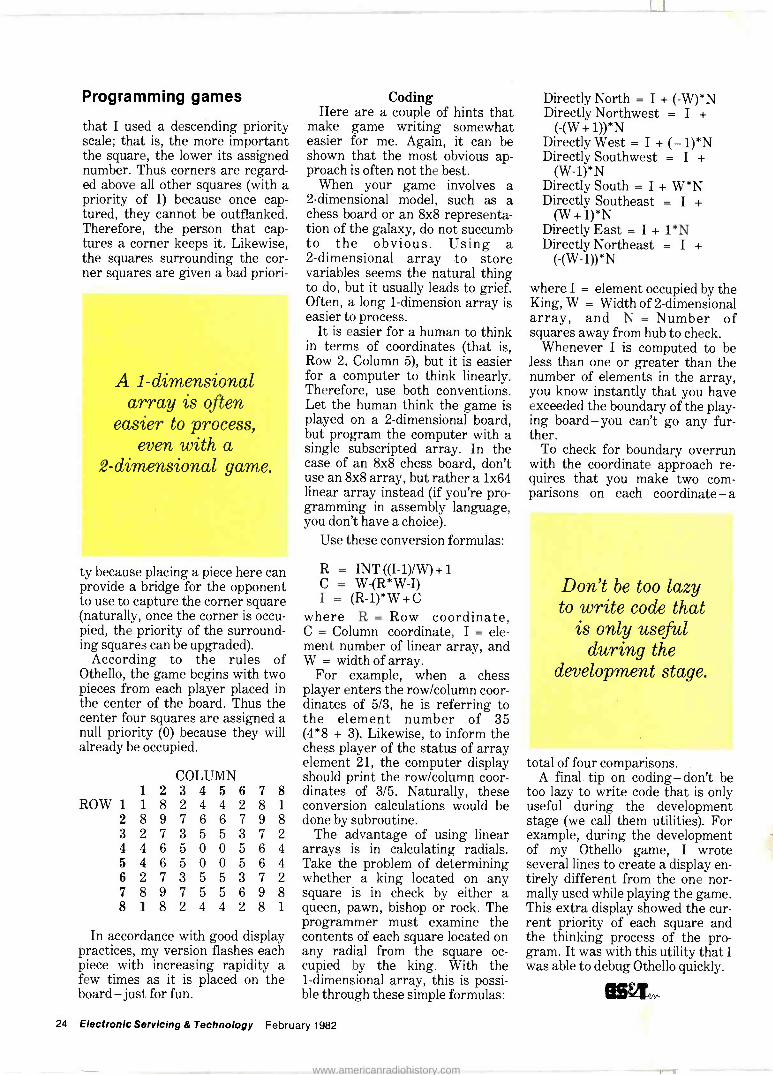
Programming games
that I used a descending priority scale; that is, the more important the square, the lower its assigned number. Thus corners are regard- ed above all other squares (with a priority of 1) because once cap- tured, they cannot be outflanked. Therefore, the person that cap- tures a corner keeps it. Likewise, the squares surrounding the cor- ner squares are given a bad priori -
A 1 -dimensional array is often
easier to process, even with a
2 -dimensional game.
ty because placing a piece here can provide a bridge for the opponent to use to capture the corner square (naturally, once the corner is occu- pied, the priority of the surround- ing squares can be upgraded).
According to the rules of Othello, the game begins with two pieces from each player placed in the center of the board. Thus the center four squares are assigned a null priority (0) because they will already be occupied.
COLUMN 1 2 3 4 5 6 7 8
ROW 1 1 8 2 4 4 2 8 1
2 8 9 7 6 6 7 9 8 3 2 7 3 5 5 3 7 2 4 4 6 5 0 0 5 6 4 5 4 6 5 0 0 5 6 4 6 2 7 3 5 5 3 7 2 7 8 9 7 5 5 6 9 8 8 1 8 2 4 4 2 8 1
In accordance with good display practices, my version flashes each piece with increasing rapidity a few times as it is placed on the board-just for fun.
Coding Here are a couple of hints that
make game writing somewhat easier for me. Again, it can be shown that the most obvious ap- proach is often not the best.
When your game involves a 2 -dimensional model, such as a chess board or an 8x8 representa- tion of the galaxy, do not succumb to the obvious. Using a 2 -dimensional array to store variables seems the natural thing to do, but it usually leads to grief. Often, a long 1 -dimension array is easier to process.
It is easier for a human to think in terms of coordinates (that is, Row 2, Column 5), but it is easier for a computer to think linearly. Therefore, use both conventions. Let the human think the game is played on a 2 -dimensional board, but program the computer with a single subscripted array. In the case of an 8x8 chess board, don't use an 8x8 array, but rather a 1x64 linear array instead (if you're pro- gramming in assembly language, you don't have a choice).
Use these conversion formulas:
R = INT ((I -1)/W)+ 1
C = W-(R*W-I) I = (R-1)*W+C
where R = Row coordinate, C = Column coordinate, I = ele- ment number of linear array, and W = width of array.
For example, when a chess player enters the row/column coor- dinates of 5/3, he is referring to the element number of 35 (4*8 + 3). Likewise, to inform the chess player of the status of array element 21, the computer display should print the row/column coor- dinates of 3/5. Naturally, these conversion calculations would be done by subroutine.
The advantage of using linear arrays is in calculating radials. Take the problem of determining whether a king located on any square is in check by either a queen, pawn, bishop or rock. The programmer must examine the contents of each square located on any radial from the square oc- cupied by the king. With the 1 -dimensional array, this is possi- ble through these simple formulas:
Directly North = I + (-W)*N Directly Northwest = I +
(-(W+ 1))*N Directly West = I + (-1)*N Directly Southwest = I +
(W-1)*N Directly South = I + W*N Directly Southeast = I +
(W+ 1)*N Directly East = I + 1*N Directly Northeast = I +
(-(W-1))*N
where I = element occupied by the King, W = Width of 2 -dimensional array, and N = Number of squares away from hub to check.
Whenever I is computed to be less than one or greater than the number of elements in the array, you know instantly that you have exceeded the boundary of the play- ing board-you can't go any fur- ther.
To check for boundary overrun with the coordinate approach re- quires that you make two com- parisons on each coordinate -a
Don't be too lazy to write code that
is only useful during the
development stage.
total of four comparisons. A final tip on coding - don't be
too lazy to write code that is only useful during the development stage (we call them utilities). For example, during the development of my Othello game, I wrote several lines to create a display en- tirely different from the one nor- mally used while playing the game. This extra display showed the cur- rent priority of each square and the thinking process of the pro- gram. It was with this utility that I was able to debug Othello quickly.
WM, 24 Electronic Servicing & Technology February 1982
1..T www.americanradiohistory.com
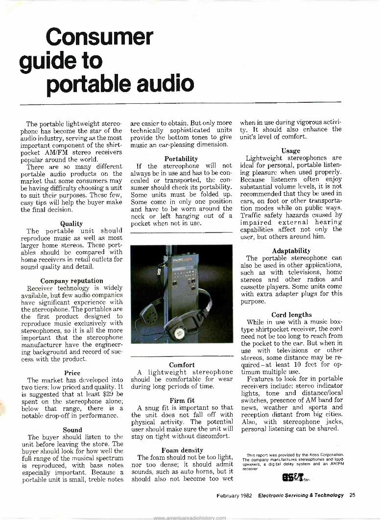
Consumer guide to
portable audio
The portable lightweight stereo- phone has become the star of the audio industry, serving as the most important component of the shirt - pocket AM/FM stereo receivers popular around the world.
There are so many different portable audio products on the market that some consumers may be having difficulty choosing a unit to suit their purposes. These few, easy tips will help the buyer make the final decision.
Quality The portable unit should
reproduce music as well as most larger home stereos. These port- ables should be compared with home receivers in retail outlets for sound quality and detail.
Company reputation Receiver technology is widely
available, but few audio companies have significant experience with the stereophone. The portables are the first product designed to reproduce music exclusively with stereophones, so it is all the more important that the stereophone manufacturer have the engineer- ing background and record of suc- cess with the product.
Price The market has developed into
two tiers: low priced and quality. It is suggested that at least $29 be spent on the stereophone alone; below that range, there is a notable drop-off in performance.
Sound The buyer should listen to the
unit before leaving the store. The buyer should look for how well the full range of the musical spectrum is reproduced, with bass notes especially important. Because a portable unit is small, treble notes
are easier to obtain. But only more technically sophisticated units provide the bottom tones to give music an ear -pleasing dimension.
Portability If the stereophone will not
always be in use and has to be con- cealed or transported, the con- sumer should check its portability. Some units must be folded up. Some come in only one position and have to be worn around the neck or left hanging out of a pocket when not in use.
Comfort A lightweight stereophone
should be comfortable for wear during long periods of time.
Firm fit A snug fit is important so that
the unit does not fall off with physical activity. The potential user should make sure the unit will stay on tight without discomfort.
Foam density The foam should not be too light,
nor too dense; it should admit sounds, such as auto horns, but it should also not become too wet
when in use during vigorous activi- ty. It should also enhance the unit's level of comfort.
Usage Lightweight stereophones are
ideal for personal, portable listen- ing pleasure when used properly. Because listeners often enjoy substantial volume levels, it is not recommended that they be used in cars, on foot or other transporta- tion modes while on public ways. Traffic safety hazards caused by impaired external hearing capabilities affect not only the user, but others around him.
Adaptability The portable stereophone can
also be used in other applications, such as with televisions, home stereos and other radios and cassette players. Some units come with extra adapter plugs for this purpose.
Cord lengths While in use with a music box -
type shirtpocket receiver, the cord need not be too long to reach from the pocket to the ear. But when in use with televisions or other stereos, some distance may be re- quired - at least 10 feet for op- timum multiple use.
Features to look for in portable receivers include: stereo indicator lights, tone and distance/local switches, presence of AM band for news, weather and sports and reception distant from big cities. Also, with stereophone jacks, personal listening can be shared.
This report was provided by the Koss Corporation. The company manufactures stereophones and loud- speakers, a digital delay system and an AM/FM receiver.
864vw
February 1982 Electronic Servicing & Technology 25
www.americanradiohistory.com

0000000 ii iti 0000004 ...... 0410 000 000 000 000 000 000 0000 000 000
SSS SSS 0000000
:000
04040000000
000000 000 000
000 900 Owe 000 000 060 000 000 000 060 000 000 woe. 0000000 9 000 000000 00000
*erne 111*moo*
000 000 00 f
000 000 000 18 -
0000i00 0
::: 222 ..i ... K.
iii
memo see see
stss
®
The programmable video game and home computer markets promise to be one of the fastest growing consumer markets of the 1980s. There are approximately 5 million game systems currently in use, and new system sales are increasing by about 50%. Cartridge sales are more than doubling annually. As more new systems are sold, more interesting new cartridge ideas are released, and game marketers devote more advertising and merchandising support to cartridges. The market for video game cartridges alone is expected to exceed $1 billion at retail by 1985. ES&T has collected some of these exciting cartridges from major games manufacturers. For more information from these manufacturers, simply circle the Reader Service numbers given at the end of this section.
1 0:24.3 8
1114 1 1
Ir
Skiing Challenge yourself to a wide varie- ty of high speed downhill or slalom runs. Trees and moguls rush by as you race through the course.
0000000000 jS2S'::::::::: i_ ..................
000 000 000 000 000 000 000 00000 000 006 000 00 000 000 000 Si::.:.2 000 000 000
: 0 000000 :ii0
26 Electronic Servicing & Technology February 1982
www.americanradiohistory.com

Fishing Derby A relaxing afternoon at the old fishing hole? Not quite. The bay is full of beautiful sunfish, and all you have to do is land them faster than your opponent. However, watch out for the shark. His voracious ap- petite makes fishing a constant challenge.
i Ice Hockey Face off. Fight for the puck. Skate down the ice past the defender for a slap -shot. Then, hurry back on defense as your opponent makes a remarkable save and a long pass to his forward.
Kaboom You have three buckets of water. The mad bomber at the top of the screen tosses bombs and you catch them in your buckets. But before you know it, the bombs are falling at a rate of 13 per second.
Laser Blast As commander of a fleet of in- tergalactic spacecraft, you come upon some unfriendly alien types. Get them before they get you and you are awarded points.
Activision
Tennis Never wait for a court again. Charging players can rush the net, lay back and play the baseline or roam the court.
Dragster Watch the countdown, shift gears, pop the clutch and burn rubber. You can rev your engine but be careful not to blow it. Sound ef- fects and grueling competition bring all the action of the dragstrip right into your livingroom.
Bridge This cartridge deals hundreds of millions of hands at random and provides a computer partner who bids by the rules. After you have established a contract, the com- puter plays as your opponents.
/wN011O R K 4 2 J 6 R
Checkers There are three different skill levels to choose from. Warm up with novice, and then tackle the tougher levels. Your computer op- ponent plots the results of each of his available moves and then picks the one that is toughest on you.
February 1982 Electronic Servicing & Technology 27
www.americanradiohistory.com

Games people play
ASTEROIDS Game Program'"
Asteroids Your spaceship is trapped in a deadly asteroid belt and you must score points by destroying the boulders before they, or the enemy spacecraft, destroy you. Hyper - space in all directions and fire your missiles to protect your spaceship.
Superman Flying faster than a speeding bullet, you use your X-ray vision to find the hideout of your enemy, Lex Luthor, and put the gang behind bars. But you must watch out for the deadly Kryptonite satellites, or you will lose your super powers.
o
3-D TIC-TAC-TOE Gama P ogram"'
3-D Tic -Tac -Toe Place four Xs or four Os in one horizontal, vertical or diagonal row, or through all the planes. Play against an opponent or against the computer in trying to complete your row first.
Atari
Backgammon Use all the strategies you know and play against the computer or another player. The program in- cludes the popular version of Acey- Deucey, in which throwing a one and a two is the name of the game.
Breakout Smash your way out of a thick wall of bricks with a tricky ball. The first few bricks are easy, but as you come closer to breaking out, it gets tougher. The program also in- cludes Breakthru, where you knock a hole in the wall in one shot.
Casino Games include blackjack (with up to four players trying to beat the house), stud poker and poker solitaire (where you can play up to 12 hands by yourself).
28 Electronic Servicing & Technology February 1982
www.americanradiohistory.com

A Game of Concentration Thirty numbers flash on the screen and a familiar object or wild card is hidden behind each. Match wits with your opponent or the com- puter in matching pairs of objects. Millions of different combinations in eight game variations keep players on their toes.
A Oars Of CONCENTRATION
Bowling Choose your alley and roll the ball. It may be a straight, curve or even a gutter ball. The score is kept automatically on the screen, frame by frame. The cartridge includes six variations of the game.
.»w, GAM( *MAY
Football You're the quarterback calling all the offensive plays, and on the defense, you're in total control. Kick, pass, run or punt for a touchdown.
.4U,M e.»
Human Cannonball Pos-tion the cannon, set the angle and pick your speed; the calcula- tions will appear on the screen. You fly through the air toward a water tower in this daredevil stunt.
Video Chess It's you against the computer in this version of the classical game. You plan your strategy to break down the computer's defenses and reach checkmate.
t t t t t t t i
W.Ift*Mad kW
VIDEO CHESS" O. P100a01~
Night Driver The road ahead is dark and wind- ing as you keep your eyes peeled for oncoming cars. The longer you stay on the road, the higher your score, but you never know what will jump out on the road at night.
NIGHT DRIVER" Gam Program "'
February 1982 Electronic Servicing & Technology 29
www.americanradiohistory.com

Games people play
Air -Sea Battle Be an artillery commander, sub- marine captain or aircraft bombar- dier in six variations of one pro- gram. Targets come from dif- ferent directions at different speeds in games such as Anti - Aircraft, Torpedo, Shooting Gallery, Polaris, Bomber and Polaris vs. Bomber.
Surround You control a moving wall as you try to trap your opponent before he traps you. It's a game of speed, wits and skill as you move and erase sections of wall. A variation in this program is Video Grafitti, in which you draw with video blocks.
Sky Diver The longer you wait to open your chute after your jump, the more points you score. After it opens, steer against varying wind velocities toward the bull's eye.
Black Jack You and up to two other card sharks are seated around the television, each armed with 200 chips. Bet up to 25 chips each hand as the computer deals the cards on the screen. (An additional set of paddle controllers is needed for the 3 -player version.)
Brain Games Race against time and distractions in the six variations of this pro- gram. Focus on a series of sym- bols, numbers or musical notes, then repeat them in order; add col- umns of numbers in the allotted time; or watch four objects appear on the screen and eliminate the one that doesn't belong.
Circus Atari As the clown bounces around in different directions, try to catch him on the teeter-totter. Send him up to pop red, white and blue balloons worth different points-the harder the pop, the more you score.
CIRCUS ATARI' Game Program"
30 Electronic Servicing & Technology February 1982
www.americanradiohistory.com

Adventure Once upon a time an evil magician stole an enchanted goblet and hid it in the kingdom. Now you must find it. Three deadly dragons and a black bat try to stop you but you use the magic sword for protec- tion.
ADVENTURE Game Program"'
,_.....
Indy 500 Race around one of many tracks in 14 1- and 2 -player variations, such as Race Cars, Crash `N Score, Tag and Ice Race. Steering controllers come with each Indy 500 game program.
Hangman Play alone or with an accomplice against the computer as you guess the missing letters to complete the mystery word. Variations include vocabularies for grades three, six, nine and high school. In the Lex- icontest variation, you and your opponent choose words for each other.
Outlaw Your gunfighter draws, kneels and aims at your opponent. Blow away walls, stagecoaches and cacti as you nail the enemy with a clever ricochet. In the Target Shooting variation, shoot at a moving target while racing against time and obstacles.
oun w-- ww 1.1031014W" ..
Combat Use your missiles, rapid-fire machine guns and single shots to arm yourself against the enemy. Blast your opponent as many times as possible for the highest score.
Golf One to four players move around the nine holes of Atari's course. You control the direction and power of your shot and get a close- up of the green for your putt. Your score is automatically recorded.
GOLF Game Program'"
February 1982 Electronic Servicing & Technology 31
www.americanradiohistory.com
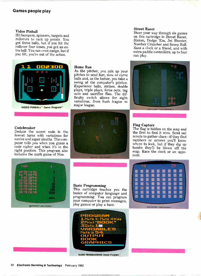
Games people play
Video Pinball Hit bumpers, spinners, targets and rollovers to rack up points. You get three balls, but if you hit the rollover four times, you get an ex- tra ball. You can even nudge, but if you tilt, you're out of the action.
VIDEO PONBALL' Game
Codebreaker Deduce the secret code in the fewest turns with variations for novice and super sleuths. The com- puter tells you when you guess a code cipher and when it's in the right position. This program also includes the math game of Nim.
11.1111.1M
Home Run As the pitcher, you mix up your pitches to send fast, slow or curve balls and, as the batter, you take a swing at the computer's pitches. Experience balls, strikes, double plays, triple plays, force outs, tag outs and sacrifice flies. The dif- ficulty switch allows for eight variations, from bush league to major league.
Basic Programming This cartridge teaches you the basics of computer language and programming. You can program your computer to print messages, play games or play a tune.
PROGRAM 1 Note Mote -i-Key
Print "BOOK " 3Goto JAI KAARIABLES Mote is 54 OUTPUT BOOK GRAPHICS
BASIC PROGRAMMING Garne Program
Street Racer Steer your way through six games on this cartridge in Street Racer, Slalom, Dodge 'Em, Jet Shooter, Number Cruncher and Scoop Ball. Race a clock or a friend, and with extra paddle controllers, up to four can play.
Flag Capture The flag is hidden on the map and the first to find it wins. Send out scouts to gather clues - if they find numbers or arrows you'll know where to look, but if they dig up bombs they'll be blown off the map. Race the clock or an oppo- nent.
32 Electronic Servicing & Technology February 1982
www.americanradiohistory.com
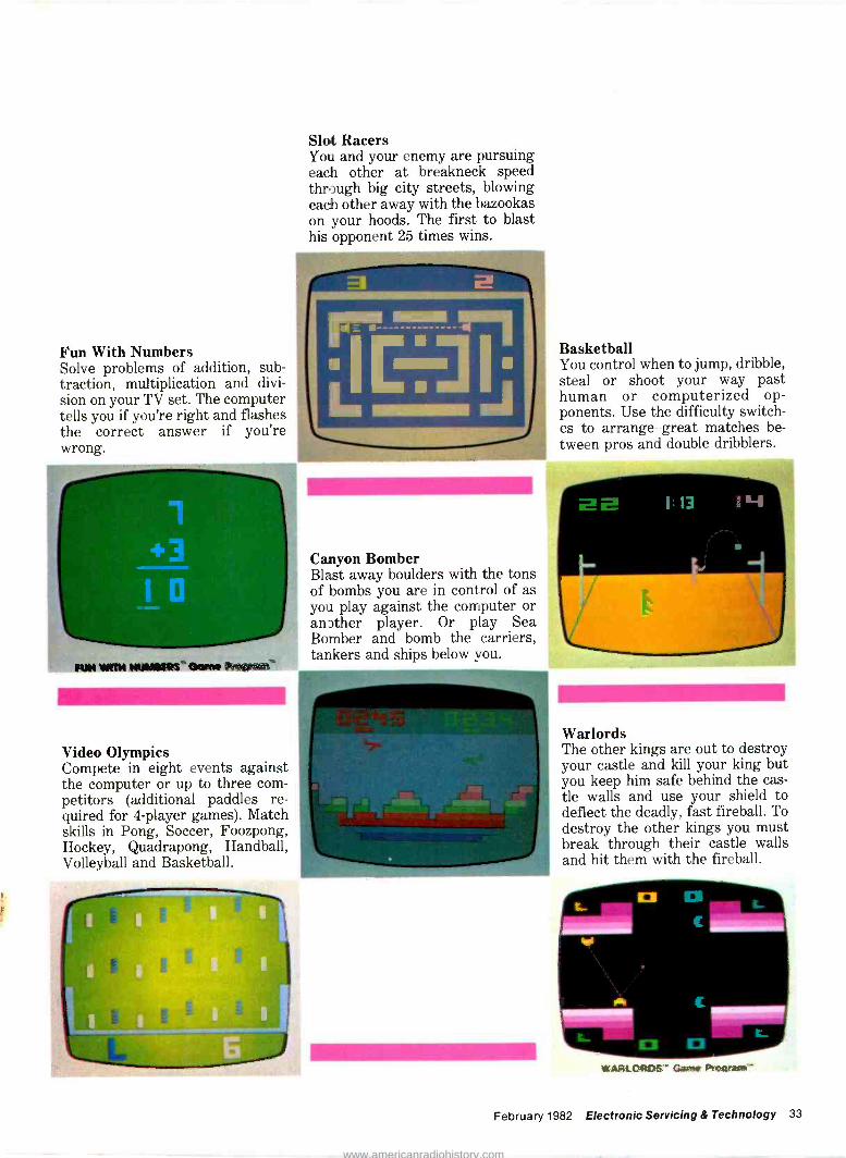
Fun With Numbers Solve problems of addition, sub- traction, multiplication and divi- sion on your TV set. The computer tells you if you're right and flashes the correct answer if you're wrong.
RIM WM iMMM1IRt ̀ Qom hopan'
Video Olympics Compete in eight events against the computer or up to three com- petitors (additional paddles re- quired for 4 -player games). Match skills in Pong, Soccer, Foozpong, Hockey, Quadrapong, Handball, Volleyball and Basketball.
Slot Racers You and your enemy are pursuing each other at breakneck speed through big city streets, blowing each other away with the bazookas on your hoods. The first to blast his opponent 25 times wins.
Canyon Bomber Blast away boulders with the tons of bombs you are in control of as you play against the computer or anDther player. Or play Sea Bomber and bomb the carriers, tankers and ships below you.
Basketball You control when to jump, dribble, steal or shoot your way past human or computerized op- ponents. Use the difficulty switch- es to arrange great matches be- tween pros and double dribblers.
Warlords The other kings are out to destroy your castle and kill your king but you keep him safe behind the cas- tle walls and use your shield to deflect the deadly, fast fireball. To destroy the other kings you must break through their castle walls and hit them with the fireball.
WARLORDS . Gserr IP*QaQam+ '
February 1982 Electronic Servicing & Technology 33
www.americanradiohistory.com

Games people play
Othello Each player takes turns trying to capture as many squares as possi- ble. You'll need a solid strategy and real cunning to be successful at this game, but don't try any il- legal moves or the computer will "razz" you. You can play against the computer at three different skill levels or against another player.
1111111111111M11111111111111
,111111111111 iii aoo : OTHELLO' Game Program'"
Space Invaders Your mission is to destroy the aliens with your laser cannon before they reach the Earth, while avoiding their bombs. When you've destroyed them all, new invaders will appear.
Pt Pc E4
Cl tie f9;lfAlf,lt4°l 5e 5e lle 52 5e 5e
R ?t ?t ?t le $ Ct
SPACE INVADERS' Oam Program'"
K.C. MUNCHKIN!
brine ynnr 1.1ncb4n, iI1 mnnrlr,J:.ul"" MyrlMrt pl OMnrnni m.ws'
K. C. Munchkin! How many Munchies can your Munchkin munch before your Munchkin's all munched out? The object is to skillfully negotiate a maze while trying to gobble the edible Munchies and avoid being munched by the Munchers. It's a game of video survival - munch or be munched.
N.A.P. Consumer Products
Intellivision The Electric Company Word Fun Monkeys swing through the jungle, capturing letters with their tails to make words. Three games are included in this program, developed in conjunction with The Children's Television Workshop for one or two players. Find A Word has learners weaving words in and out of each other, Word Hunt sends them into the jungle to find missing letters and Word Rocket has them blasting vowels into the sky to make words out of clouds of consonants.
34 Electronic Servicing & Technology February 1982
www.americanradiohistory.com

Armor Battle Two players move across the battlefield, scanning the horizon for tanks and hoping to fire a split second sooner than the enemy. When you have beaten your oppo- nent, move to one of hundreds of new battlefields.
Las Vegas Poker and Blackjack One or two players can play 5 -card stud, 5 -card draw or 7 -card stud poker against a dealer who raises, drops and even bluffs. Blackjack is also included in this cartridge.
Tennis Play an entire 3 -set match, and each game will be different and ex- citing. You control ball placement, velocity and strategy to make it a game of wits as well as dexterity. Even the crowd turns their heads to follow the ball and cheer at the right time.
Horse Racing Up to six players look over the tout sheet, pick their horses, handicap them and bet. Watch as the horses move around the track and hit 15 to 1 exactas.
ee 0'1
The Electric Company Math Fun This game, developed in conjunc- tion with the Children's Television Workshop, makes solving addi- tion, subtraction, multiplication and division problems fun. One or two players race their gorillas along the river bank, ducking past obstructing animals. The cartridge accommodates a wide range of learning levels.
Las Vegas Roulette One or two players place their bets and watch as the roulette wheel turns toward the lucky number. A payoff table and odds listing are in- cluded in the program.
U.S. Ski Team Skiing Don't cut corners too closely as you wind down these downhill or slalom courses, or you'll go tum- bling! Up to six players jump moguls, edge through turns and race downhill against the clock in this U.S. Ski Team licensed game.
Auto Racing Players race each other or the clock as they guide their Formula 1 through the course. Five dif- ferent race cars and five different courses provide variety, along with skidding cars and unexpected hairpin turns.
February 1982 Electronic Servicing & Technology 35
www.americanradiohistory.com

Games people play NHL Hockey The National Hockey League has licensed this game, in which two players move their teams across the ice. The program includes face offs, trapping, interception and a penalty box.
Sea Battle Lay invisible minefields where you think the enemy ships will travel, then man your battle stations and fire shells and torpedoes. Two players compete, using long-range and closeup views from their ships.
NBA Basketball Each 3 -man team can dribble, pass in any direction, rebound, jump, block, steal and take set shots. Two players race a 24 -second clock in four quarters in this game, licensed by the National Basket- ball Association.
Yahtzee This dice game combines strategy and chance as players accumulate points by rolling certain number combinations. Developed by Milton Bradley Company.
i,âwe:....
W ww, irrzee F. e; . en*. M. E Y'
1
3. Me w.Inumo t e ie m1F K ilea e
R uu e kemaultI{{:s. a
anni4l' Sine..4 O Mr n.
'l 3.¢mRi 3 * Y ein
w
Texas Instruments
A-Maze-Ing The 13 options on this program of- fer a total of 5200 different varia- tions, from simple mazes to a cat - and -mouse chase situation.
Activision 65 Atari 88 Intellivison 87 N.A.P. Consumer Products 88 Texas Instruments 69
36 Electronic Servicing & Technology February 1982
www.americanradiohistory.com

More light on optical -fiber systems
Courtesy of GTE
Like most communications, systems, fiber -optics systems re- quire a transmitter, a transmis- sion medium and a receiver. Fiber - optics systems use a light transmitter and receiver, and a glass or plastic fiber is the transmission medium.
Transmitter A light transmitter consists of
two parts, a light source and a modulator. The modulator imposes the information on the source. Most modulators accomplish this by turning the light source on and off or by varying the intensity of the light.
Two kinds of light sources are suitable for fiber-optic communica- tions: the LED (light -emitting diode) and the laser (light amplification by stimulated emis- sion of radiation).
There are several types of lasers but the one most commonly used for fiber-optic communications is the semiconductor laser, which is
also known as an injection or junc- tion diode laser. The LED is also a semiconductor junct ion diode device, so some knowledge of junc- tion diodes is helpful in under- standing the two light sources.
As shown in Figure 1, junction diodes are made from two kinds of semiconductor material: a positive (P) type that has a deficiency of electrons in its atoms and a negative (N) type that has an ex- cess of electrons in its atoms. If a positive voltage is connected to the P -type material and a negative voltage is connected to the N -type, forward bias is applied to the diode and current will flow through it. The amount of current is deter- mined by the amplitude of the ap- plied voltage.
Reversing the polarity of the voltage so that negative is applied to P and positive is applied to N cuts off the current flow. This is known as reverse bias. The diode can be switched on and off millions of times per second by reversing
DIODE
P N
SWITCH
BATTERY
Figure 1. Junction diodes are made from positive (P) and negative (N) semiconductor material.
HIGHLY POLISHED END uuNiNlriiii
1iiiNiiaiadiuiiiiiiitiiiiiiiiiiiiii 1
Figure 2. The semiconductor injection laser is a junction diode with both ends pol- ished to reflect light.
the polarity of the applied voltage. When forward bias is applied to
the LED, the electrons in the relatively unstable N -type atoms receive energy from the battery. This extra energy allows them to cross the junction and current flows.
After crossing the junction, the electrons lose energy and enter the atoms of the P material. Some of the energy the electrons lose is emitted as light from the LED. The intensity of the light emission varies with the amount of current flowing through the junction.
Light generated by atomic ac- tion of this kind is known as luminescent, as opposed to in- candescent light, which is generated by heating an element. Ordinary light bulbs are incandes- cent and are not suitable for high speed communications.
Referring to Figure 2, the semiconductor, injection laser is a junction diode with both ends polished to reflect light. One end is more highly polished than the other.
Forward bias causes the N -material electrons to raise to a high energy level and move into the junction. As a high-energy electron falls to a lower energy level, it emits a small burst of light. The light may strike another electron and raise it to a high energy level. When this electron falls to a lower energy level, it also emits a burst of light. These bursts of light are reflected when they hit the polished ends of the junction. A stream of light is created that moves back and forth between the ends of the junction. When these light waves reach a high enough intensity, some of the light will emerge from the least polished end of the junction in the form of a beam of light.
The frequency of the light generated by the laser is a function of the diode material and temperature. The intensity of the light increases with the current flow.
The light wave spectrum is generally expressed in wavelength rather than frequency. The shorter the wavelength, the higher the fre- quency. Typical wavelengths for both LED's and lasers are in the
February 1982 Electronic Servicing & Technology 37
www.americanradiohistory.com

Optical -fiber
800 to 850nm range. A nanometer is one billionth of a meter.
LED and laser comparison The emission from an LED is
lambertian, which means the light rays emanate over an entire hemisphere. Another term used to describe the way light emanates from an LED is isotropic, which means the light rays are emitted at all angles. This makes it difficult to efficiently couple an LED to a fiber.
The LED output is nearly direct- ly proportional to the current through the junction. The change in lightpower output is essentially linear over a large range of input current, so LEDs can be amplitude modulated.
Some LEDs tan be switched at rates up to 200 million a second, although 50 million a second is about the fastest rate used in ac- tual practice. Switching rates are usually stated in megabits per sec- ond (Mops). A megabit is one million bits or pulses.
The modulation method that switches the source on and off is called pulse code modulation (PCM). This is the modulation method commonly used in digital systems.
The laser is a threshold device. It "turns on" and provides a large amount of light power when the drive current reaches a threshold value. The light power output ver- sus current input is linear over a very limited range, so lasers are not suitable for amplitude modula- tion (AM).
The spectral width of laser light is much narrower than that of LEDs. Therefore, lasers can be switched at much faster rates than LEDs because material dispersion is not a problem. Material disper- sion is explained later, in the discussion of optical fibers. Lasers can be switched at gigabit (Gb/s) rates, so lasers are very suitable for PCM or other forms of pulse modulation. A gigabit is one billion bits.
Laser beams are directional, so coupling to the fiber is more effi- cient than for LEDs. Lasers also have a higher power output than LEDs.
Terms used to describe laser light are coherent and collimated.
Coherent means that the rays are in phase and reinforce each other. The light from a coherent light source has only one wavelength. Collimated means that all the rays travel on parallel paths. Coherence and collimation are ideal proper- ties for a light source to be used in optical fiber communications. Lasers approach this ideal.
Other requirements for a light source to be used in mass com- munications are low cost and high reliability. In the telephone net- work, for example, sources must be able to provide many years of continuous stable operations at or- dinary room temperatures. They should also be capable of being effi- ciently coupled to the fiber.
Another factor that must be con- sidered is the distance bandwidth product. This is a "figure of merit" for a system. The product is large- ly determined by the light source.
Lasers have a better coupling ef- ficiency and distance -bandwidth product than LEDs. On the other hand, LEDs are lower in cost and because of simpler construction, generally more reliable than lasers. Specially constructed LEDs with greatly improved coupling efficiencies are available but they cost more and have a shorter life than the standard type.
Generally speaking, LEDs are used for relatively short, limited - bandwidth systems. Lasers are re- quired for long -haul broadband systems.
Modulators The second part of a light
transmitter is the modulator. Modulators used in fiber-optic systems are similar to those used for microwave radio (see Figure 3).
If a frequency -division multiplexer (FDM) is used as the modulator, it will amplitude modulate the light source to pro- duce varying intensity light. if a time -division multiplexer (TDM) is used as the modulator, it will switch the source on and off at a digital rate.
FDM combines information channels represented by analog signal voltages, which are con- tinuously varying in amplitude. The signals are transmitted at the same time but separated in fre- quency.
A TDM combines information
channels represented by the presence and absence of signal voltage pulses of constant amplitude. The time position of a pulse, relative to other pulses, determines the voltage quantity it represents. The signals are transmitted at the same frequency but separated in time.
FDM signals and their com- ponents parts are referred to as analog; TDM signals and their component parts are referred to as digital. Digital signals are more commonly used for fiber optic com- munications systems because it is easier to detect on -off states than it is to detect variations in light in- tensity.
Transmission path The glass fibers used in fiber -
optical cable are very small, with typical diameters from 50 to 200µm. The fiber shown in Figure 4 has a cylindrical core with a uniform index of refraction. The core is encased in a concentric layer called the cladding. The clad- ding index of refraction is lower than that of the core.
A light ray entering the core at one end of this fiber will travel down its length and exit at the other end. This action conforms to the reflection principle of physical optics, which says: When a light ray passes from one optical transmission medium to a boun- dary of another medium with a lower index of refraction, the ray will be reflected back into the original medium.
This reflective action occurs over and over again as the light travels down the core. A minute amount of light intensity is lost each time reflection occurs. As the light traverses the fiber, additional losses occur, largely due to im- purities in the fiber. These two fac- tors, reflection loss and fiber loss, are the main components of at- tenuation per unit length of fiber.
Light transmission is affected by another cable characteristic, input light acceptance.
Figure 5 shows three light rays, a, b and c, entering an optical fiber. Ray a enters the fiber along the longitudinal axis and travels down the cable as shown. Ray b enters the cable at an angle to the longitudinal axis less than the angle O and is reflected down the cable as shown. Ray c enters the
38 Electronic Servicing & Technology February 1982
www.americanradiohistory.com
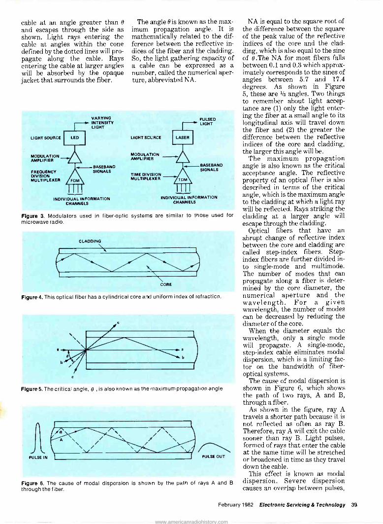
cable at an angle greater than B
and escapes through the side as shown. Light rays entering the cable at angles within the cone defined by the dotted lines will pro- pagate along the cable. Rays entering the cable at larger angles will be absorbed by the opaque jacket that surrounds the fiber.
The angle O is known as the max- imum propagation angle. It is mathematically related to the dif- ference between the reflective in- dices of the fiber and the cladding. So, the light gathering capacity of a cable can be expressed as a number, called the numerical aper- ture, abbreviated NA.
LIGHT SOURCE
MODULATION AMPLIFIER
VARYING INTENSITY LIGHT
- BASEBAND FREQUENCY SIGNALS DIVISION MULTIPLEXER
INDIVIDUAL INFORMATION CHANNELS
PULSED LIGHT
LIGHT SOURCE
MODULAT ON AMPLIFIER
BASE BAND SIGNALS
TIME DIVISION MULTIPLEXER
INDIVIDUALINFORMATION CHANNELS
Figure 3. Modulators used in fiber-optic systems are similar to those used for microwave radio.
CLADDING
CORE
Figure 4. This optical fiber has a cylindrical core and uniform index of refracticn.
Figure 5. The critical angle, B , is also known as the maximum propagation angle.
J PULSE IN
\ PULSE OUT
Figure 6. The cause of modal dispersion is shown by the path of rays A and B
through the fiber.
NA is equal to the square root of the difference between the square of the peak value of the reflective indices of the core and the clad- ding, which is also equal to the sine of 0.The NA for most fibers falls between 0.1 and 0.3 which approx- imately corresponds to the sines of angles between 5.7 and 17.4 degrees. As shown in Figure 5, these are 1/2 angles. Two things to remember about light accep- tance are (1) only the light enter- ing the fiber at a small angle to its longitudinal axis will travel down the fiber and (2) the greater the difference between the reflective indices of the core and cladding, the larger this angle will be.
The maximum propagation angle is also known as the critical acceptance angle. The reflective property of an optical fiber is also described in terms of the critical angle, which is the maximum angle to the cladding at which a light ray will be reflected. Rays striking the cladding at a larger angle will escape through the cladding.
Optical fibers that have an abrupt change of reflective index between the core and cladding are called step -index fibers. Step - index fibers are further divided in- to single -mode and multimode. The number of modes that can propagate along a fiber is deter- mined by the core diameter, the numerical aperture and the wavelength. For a given wavelength, the number of modes can be decreased by reducing the diameter of the core.
When the diameter equals the wavelength, only a single mode will propagate. A single -mode, step -index cable eliminates modal dispersion, which is a limiting fac- tor on the bandwidth of fiber - optical systems.
The cause of modal dispersion is shown in Figure 6, which shows the path of two rays, A and B, through a fiber.
As shown in the figure, ray A travels a shorter path because it is not reflected as often as ray B. Therefore, ray A will exit the cable sooner than ray B. Light pulses, formed of rays that enter the cable at the same time will be stretched or broadened in time as they travel down the cable.
This effect is known as modal dispersion. Severe dispersion causes an overlap between pulses,
February 1982 Electronic Servicing & Technology 39
www.americanradiohistory.com

I
Optical -fiber
which makes it difficult to distinguish between them. Also, overlap may make it appear that a pulse is present where one is not. It is apparent that allowing more space between pulses, i.e., sending fewer pulses per unit time, could alleviate overlap. However, the in- formation capacity (bandwidth) of the system would be reduced.
As previously stated, single - mode fiber eliminates modal dispersion. However, its core diameter is so small that it is dif- ficult to achieve and maintain effi- cient coupling between a light source and a single -mode cable under other than laboratory condi- tions. A step -index, multimode cable has a much larger core diameter so efficient coupling can be achieved, but it has the disad- vantage of dispersion effects.
A compromise between the step - index, single -mode and multimode fibers is the graded index fiber. This fiber provides a good coupling efficiency and reduces modal dispersion. This is accomplished by using a graded index of refraction across the fiber core instead of the uniform index of refraction used for step -index core.
The graded -index, multimode fiber has an index of refraction that is maximum at the center of the core and decreases with radial distance from the center. Because the speed of light is inversely pro- portional to the index of refraction of the material through which it propagates, rays traveling along the centerline will travel lower than those traveling off the centerline. The centerline rays travel a shorter distance at a slower speed. The offcenter rays travel a longer distance at a faster speed, so the rays exit the cable at more nearly the same time than is the case with the step -index, multimode fiber. The pulse spreading is substantially less for graded index multimode fiber than it is for step index multimode fiber. For systems of appreciable length, pulse spreading must be minimized because it is a limiting factor on the bit rate capacity (bandwidth). Graded index or single -mode is the fiber of choice for these systems. Figure 7 shows the modal dispersion of the three basic fiber types.
Material dispersion Another dispersion effect is
called material dispersion. It is a result of the fact that different wavelengths of light travel at dif- ferent velocities through a given medium.
Practical light sources emit light at different wavelengths. An LED may have a wavelength spread of 50nm. A laser is much better in this respect; its spread is on the order of 4 nm.
Material dispersion is also a limiting factor on bit rate capacity. This effect is present in all types of cable. One way it could be reduced
is by a truly monochromatic light source (one which radiates light at only one wavelength). Another way material dispersion can be reduced is by using long wavelength transmission. Material dispersion approaches zero at a wavelength around 1.3µm. Material dispersion is also referred to as wavelength dispersion.
Attenuation Attenuation is another impor-
tant characteristic of an optical fiber cable. Fiber attenuation is measured in decibels the same as
CROSS INDEX SECTION PROFILE
SINGLE- MODE STEPPED- INDEX
MULTI- MODE STEPPED- INDEX
MULTI- MODE GRADED INDEX
LIGHT PATH INPUT PULSE
l°.
i
OUTPUT PULSE
i
l
Figure 7. Modal dispersion varies with different types of fibers.
LIGHT SIGNALS
ELECTRICAL PHOTO DEMULTI DIODE DETECTOR
PLEXER DRIVER SIGNALS
Figure 8. An optical receiver consists of a photodiode detector, a driver amplifier and a demultiplexer.
HIGH ELECTRON ENERGY LEVEL
EON
LIGHT
LOW ELECTRON ENERGY LEVEL
Figure 9. Light striking an electron will raise it to a higher energy level, creating the avalanche effect.
40 Electronic Servicing & Technology February 1982
www.americanradiohistory.com

wire attenuation. A decibel is 10 times the logarithm of the ratio of two power levels. For example, if the ratio of the power input to the power output of a 1 -kilometer fiber is 10, the fiber has an attenuation of 10dB per kilometer; if the ratio is 100 the attenuation is 20dB per kilometer.
In a wire cable system, a prin- cipal cause of attenuation is elec- trical resistance. The optical equivalent of electrical resistance is called absorption, which, in this particular case, means the conver- sion of light into heat.
One cause of absorption is im- purities in the core material. Im- purities can be reduced by careful- ly controlling the core material.
Another cause of absorption loss is scattering effect. Scattering loss results from fluctuations in the glass density and imperfections at the core/cladding boundary. Again, careful construction and quality control can reduce these losses.
Scattering loss is also inversely proportional to the fourth power of the light wavelength, so scattering losses are lower at longer wavelengths. However, efficient, cost-effective, reliable light sources and detectors are current- ly limited to wavelengths from about 0.8 to 1.Opm. Intensive research and development efforts are under way to perfect sources and detectors that provide satisfactory operation at longer wavelengths.
Radiation losses are also present in fiber optical systems. Radiation losses result from minute bends in the fiber and from dirt or abra- sions on the fiber's outer surface. Microbends often occur during cable manufacture. These can be minimized by avoiding contact be- tween the fibers and other substances - as can dirt and abra- sions. Again, careful fabrication and quality control are important.
Total cable losses vary greatly between types of cable and for dif- ferent wavelengths, but usually range between 2 and 20dB per kilometer. If the attenuation specifications are being used to judge the relative transparency between two or more cables, it is important to be sure the com- parison is made for identical lengths of cable and at the same wavelength of light.
Another source of losses in a system are connectors and splices. These losses result from misalign- ment and reflective discontinuity at the junction. Splices have a lower loss than connectors because splices are carefully aligned and fusion welded or the joint is per- manently bonded with index - matching, splicing epoxies that reduce reflection discontinuities. Connectors are detachable, so their alignment is less precise. Splice losses range from about 0.1 to 0.6dB; Connector losses are in the order of 1.0 to 2.OdB.
Optical receiver As shown in Figure 8, an optical
receiver consists of a photodiode detector, a driver amplifier and a demultiplexer. The following paragraphs discuss each of these parts in turn.
At the receiving end of the op- tical communications system, the first step in recovering the in- telligence used to modulate the transmitting light source is to con- vert the incoming light back to electrical signals. The device used to accomplish this conversion is called a detector or demodulator. Two types of photodiodes are most useful for this purpose. One of these diodes consists of a PN junc- tion with an intrinsic layer be- tween the P and N regions. It is known as a PIN diode. The other diode is the avalanching photodiode (APD).
In each of these diodes, light striking at or near the junction will raise the energy level of electrons in the junction. In effect, the resistance of the junction is lowered, which allows current to flow (or the flow of current to in- crease) through the junction and therefore through the external cir- cuit across the diode.
The avalanche photodiode is more efficient than the PIN. As shown in Figure 9, light striking an electron will raise it to a higher energy level. This electron strikes two other electrons and increases their energy level although the original electron loses energy in the process. The two high energy electrons strike additional elec- trons, boosting them to the high energy level. This avalanche pro- cess continues with an increasing number of electrons achieving higher energy levels.
Because higher energy electrons in the junction represent current flow, the avalanche effect causes a gain in signal power through th diode. Because they have gain, APDs have better sensitivity than PIN diodes.
The sensitivity of an optical detector is defined in terms of the minimum light input required to provide a given performance level. The performance level is stated in terms of signal to noise ratio for analog systems and in terms of bit error rate for digital systems.
The APD is more suitable than the PIN for systems with large bandwidth requirements. However, APDs have the disad- vantages of high bias voltage re- quirements and temperature sen- sitivity. These factors make it necessary to provide a regulated bias supply with voltages in the order of 100 to 400V. Operating at higher bias voltages may also re- quire additional circuitry to com- pensate for temperature -gain variations.
The electrical output signals from the photodetector are con- nected to the input of a driver amplifier. The signals at this point may be either analog or digital. The amplifier design is essen- tially the same in either case. It is important that this amplifier be of a low noise, broadband design and that it does not load -down the photodiode.
The output of the amplifier is an exact replica of the baseband signals used to modulate the light transmitter of the distant end. These signals are passed through the demultiplexer to separate and recover the original information channels.
Optical fiber vs. wire cable Fiber optical cable has several
advantages in comparison to wire cable. One of these is fiber's im- munity to electromagnetic in- terference. Glass is an insulator so current cannot be induced in it from surrounding sources. Fiber cable may be run parallel and adja- cent to power lines without picking up any interference. Similarly, light signals on fiber cable do not cause electromagnetic radiation, so signals on the cable are in- herently secure against eavesdrop- ping. This is particularly impor- tant for military applications and
February 1982 Electronic Servicing & Technology 41
www.americanradiohistory.com

Optical -fiber
voids the necessity for the complex encryption devices used for wire and radio communications.
A multipair fiber cable is much smaller than a multipair copper cable capable of carrying the same amount of traffic. This is an impor- tant advantage when installing cable in crowded ducts under city streets. Also, fiber cable is more flexible and lighter weight, which makes it easier to "snake" through duct. Fiber cable is more resistant to heat and moisture than copper cable, which is an advantage where ducts are shared with steam and water pipes.
Signals are attenuated as they pass through any transmission medium. "Repeater" amplifiers are inserted at intervals along the path to overcome the signal loss due to attenuation. The distance between repeaters is determined by the path attenuation. The greater the attenuation per unit length, the more repeaters re- quired for a given path.
High quality optical fiber cable has substantially less attenuation than twisted -pair or coaxial cable, so a fiber system requires fewer repeaters than either of these wire systems. This is an economical ad- vantage, but the fiber -optical system repeater is more complex than the wire system repeater, as shown in the following discussion of Figure 10.
Referring to the figure, analog signals enter the terminal and are converted to PCM signals (encod- ed) by the PCM channel bank (MUX). The digital signals are amplified and used to modulate the LED.
The light output pulses of the LED are carried over an optical fiber cable to the repeater input. The photodiode at the repeater in- put converts the light pulses to electrical pulses.
The electrical pulses are detected, amplified, retimed and regenerated by the PCM repeater. The PCM repeater output pulses are converted back to light pulses by another LED. These pulses are transmitted over optical fiber to the distant terminal.
At the terminal the light signals are again converted to electrical pulses. These pulses are processed and decoded, just as any PCM
received signals, to return them to their original analog form. Signals to be transmitted in the opposite direction go through the same pro- cess.
A conventional wire cable system operates in a similar man- ner but does not require any of the optical components.
In a typical system several repeaters are required between terminals. Because an optical system requires fewer repeaters, the total cost of repeaters for an optical system of appreciable length will be less than the repeater costs for a wire system of the same length. The repeater cost comparison is even more favorable when optical systems are com- pared to coaxial cable systems but is not so favorable when the com- parison is made to microwave radio systems.
Currently, the greatest use of optical fiber transmission is in digital trunks between telephone offices. This application has won wide acceptance by telephone com- panies. A substantial portion of the future requirements for high - density trunks will be filled by fiber optics rather than paired cop- per cable, coaxial cable or microwave radio.
Optical fiber has a greater band- width than wire -cable. The advan- tages of a wide bandwidth are that a greater volume and variety of signals can be transmitted over a wideband system. The types of signals that are transmitted over telecommunications systems, in order of bandwidth requirements are:
Voice; Special services; Data - low, medium and high speed; Television, including high fidel- ity music. Special services include health-
care systems such as medalert, security systems, viewdata, energy management, facsimile, teletype and telex. Figure 11 charts the ability of various transmission systems to carry the types of signals listed above.
Coaxial cable systems have the greatest broadband capability. There are coaxial cable television systems in service that carry more than 50 TV channels. Eight video channels per fiber is the maximum achieved by fiber -optics to date,
although a 9 -channel experimental system is planned.
Component linearity problems are the limiting factors on the fiber system. When these problems are solved, the TV channel capacity of optical fiber systems may equal or surpass that of coaxial systems. As previously stated, the optical/elec- trical conversion step adds to the cost of fiber systems, but they have the advantage of greater repeater spacing. Repeaters are known as trunk amplifiers in cable television systems.
There are several techniques for transmitting video over optical fibers. The simplest method is il- lustrated in Figure 12. The video- baseband, electronic signals are used to intensity modulate an LED.
The maximum path length is established by the light source out- put power, the cable loss, the photodetector sensitivity and the required signal-to-noise ratio of the video output signal at the receiving end. Considering all these factors, the path loss of the optical fiber is limited to around 10 to 15dB, which equates to a fiber length between 3 and 6km. In its most straight -forward form, this system requires an individual fiber for each video signal.
Wavelength division multiplex- ing (WDM) is a technique for transmitting two or more optical signals over a single fiber. Light sources operating at different wavelengths are used in systems of this type. At the transmitting end, the sources' outputs are cou- pled to a single fiber and their out- puts are separated at the receiving end. If each source is modulated with a different signal, several signals can be sent over a single fiber, as shown in Figure 13.
Another method for transmit- ting video is shown in Figure 14. The light source is intensity modulated with a frequency - modulated radio frequency carrier. Video signals are used to modulate the rf carrier, which might be in the 30 to 300MHz range; cor- responding to the entire TV VHF band.
These frequency -modulated, intensity -modulated (FM -IM) systems can use a laser instead of an LED to achieve a higher signal- to-nois ratio than the previously described systems. The permissi-
42 Electronic Servicing & Technology February 1982
www.americanradiohistory.com
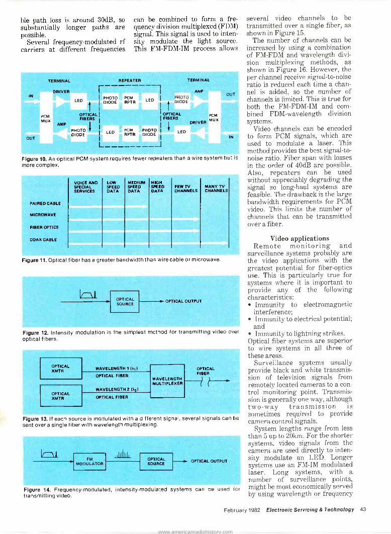
ble path loss is around 30dB, so substantially longer paths are possible.
Several frequency -modulated rf carriers at different frequencies
can be combined to form a fre- quency division multiplexed (FDM) signal. This signal is used to inten- sity modulate the light source. This FM-FDM-IM process allows
TERMINAL
IN
PCM MUX
OUT
DRIVER
AMP
LED
REPEATER ---------, PHOTO DIODE
OPTICAL FIBERS
PHOTO LED DIODE
PCM RPTR
PCM RPTR
TERMINAL
PHOTO DIODE -
I OPTICAL I FIBERS
PHOTO I
DIODE LED
AMP
DRIVER
PCM MUX
OUT
IN
Figure 10. An optical PCM system requires fewer repeaters than a wire system but is more complex.
VOICE AND SPECIAL SERVICES
PAIRED CABLE
MICROWAVE
FIBER OPTICS
COAX CABLE
LOW SPEED DATA
MEDIUM SPEED DATA
HIGH SPEED DATA
FEW TV CHANNELS
MANY TV CHANNELS
Figure 11. Optical fiber has a greater bandwidth than wire cable or microwave.
OPTICAL SOURCE
OPTICAL OUTPUT
Figure 12. Intensity modulation is the simplest method for transmitting video over optical fibers.
OPTICAL XMTR
WAVELENGTH 1 (XI)
OPTICAL XMTR
OPTICAL FIBER
WAVELENGTH 2 (X2)
OPTICAL FIBER
WAVELENGTH MULTIPLEXER
OPTICAL FIBER
Figure 13. If each source is modulated with a different signal, several signals can be sent over a single fiber with wavelength multiplexing.
FM MODULATOR
OPTICAL SOURCE
--s OPTICAL OUTPUT
Figure 14. Frequency -modulated, intensity -modulated systems can be used for transmitting video.
several video channels to be transmitted over a single fiber, as shown in Figure 15.
The number of channels can be increased by using a combination of FM-FDM and wavelength divi- sion multiplexing methods, as shown in Figure 16. However, the per channel receive signal-to-noise ratio is reduced each time a chan- nel is added, so the number of channels is limited. This is true for both the FM-FDM-IM and com- bined FDM-wavelength division systems.
Video channels can be encoded to form PCM signals, which are used to modulate a laser. This method provides the best signal-to- noise ratio. Fiber span with losses in the order of 40dB are possible. Also, repeaters can be used without appreciably degrading the signal so long -haul systems are feasible. The drawback is the large bandwidth requirements for PCM video. This limits the number of channels that can be transmitted over a fiber.
Video applications Remote monitoring and
surveillance systems probably are the video applications with the greatest potential for fiber -optics use. This is particularly true for systems where it is important to provide any of the following characteristics:
Immunity to electromagnetic interference; Immunity to electrical potential; and Immunity to lightning strikes.
Optical fiber systems are superior to wire systems in all three of these areas.
Surveillance systems usually provide black and white transmis- sion of television signals from remotely located cameras to a con- trol monitoring point. Transmis- sion is generally one way, although two-way transmission is sometimes required to provide camera control signals.
System lengths range from less than 5 up to 20km. For the shorter systems, video signals from the camera are used directly to inten- sity modulate an LED. Longer systems use an FM -IM modulated laser. Long systems, with a number of surveillance points, might be most economically served by using wavelength or frequency
February 1982 Electronic Servicing & Technology 43
www.americanradiohistory.com

Optical -fiber
division multiplexing to reduce the number of fibers required.
Broadcast TV Practically all of the optical fiber
video transmission methods have been used for TV broadcast ap- plications. The systems must transmit a color video signal with a 5MHz bandwidth plus an audio signal with a 15kHz bandwidth. The audio uses a subcarrier above the video baseband.
Fiber optics are used for short links; studio to transmitter; auditorium, stadium or theater to studio; or as end links in the broadcast network. Industry stan- dards specify a minimum signal-to- noise ratio of 58dB, end -to -end for a long -haul broadcast link. Since the noise contributions of the end links are only a part of the total system noise, their performance must be better than that of the total system. Consequently, the end link signal-to-noise ratio specification is 67dB minimum.
The first fiber end link to a TV broadcast network was installed between a telephone company cen- tral office in downtown Tampa, FL and Tampa Stadium. The link is 8km long and has a repeater located 6.6km from the central of- fice. The light source is a laser diode. The modulation method is FM -IM.
During the 1980 Winter Olym- pics, two optical fiber video links were used to transmit signals a distance of 3.3km, from the games to the Lake Placid central office. Diode lasers and FM -IM were also used for this path. The upcoming 1984 Olympics will use optical fiber systems to transmit video signals from several locations to a Los Angeles central office. Digital transmission will be used with a line rate of 90 megabits per sec- ond.
Voice frequency transmission Telephone companies define a
voice channel bandwidth as 300 to 3000Hz. Voice channels are used to carry electrical signals analogous to conversations or data signals that have been converted to analog form.
Several methods are used to multiplex vf channels for carrier
transmission over twisted pair, coax or microwave radio.
Low density analog systems use double sideband modulation with carriers in the 8 to 140kHz range to frequency division multiplex up to 6 vf channels. High density systems use single-sideband, suppressed -carrier modulation to multiplex up to 600 vf channels.
Digital systems use pulse code
modulation to time division multiplex 24 vf channels into the 1.544 megabits per second T1 car- rier or 48 channels into the 3.12 megabits per second TIC carrier. Digital systems require a greater bandwidth than an analog system with the same number of channels because a signal in the general form of a sine wave must be sam- pled at least twice per cycle to be
FM MODULATOR
FM MODULATOR
IIII1III, IIII11 OPTICAL SOURCE
OPTICAL OUTPUT
Figure 15. With FM -frequency division multiplexing -IM, several video channels can be transmitted over a single fiber.
CAMERAS
FM MODULATOR
FM
U MODULATOR
N t MODULATOR FM
U L ------------J
i OPTICAL TRANSMITTER
OPTICAL FIBER
r DIP
FM MODULATOR
D
Ç7HFM MODULATOR I Dy I F
MODULMATOR L------------
fz
x,
OPTICAL TRANSMITTER I
WAVELENGTH MULTIPLEXER
OPTICAL FIBER
Figure 16. When FDM-FM is combined with wavelength division multiplexing, the number of channels can be increased.
VF CHAN- NELS
FREQUENCY DIVISION MULTI- PLEXER
r
BASE BAND
FDM MODEM
70 MHz
i OPTI- CAL T/R
'OPTICAL FIBER 70
OPTI- MHz MICRO- CAL WAVE
1 T/R RADIO
J
Figure 17. Systems with a fiber -optics link to microwave radio are being developed.
44 Electronic Servicing & Technology February 1982
www.americanradiohistory.com

accurately represented digitally. For example, a signal with a 4000Hz bandwidth must be sam- pled at a rate of 8,000 times per second, minimum.
The outputs of any of the above multiplex systems can be con- verted to light signals for transmission over optical fibers. The low -density analog carrier can be used to intensity modulate an LED in a short range FDM-IM op- tical system.
There is a demand for this kind of low -density system to serve as an entrance link to power generat- ing stations. The insulating quali- ties of the fiber protect personnel and equipment from voltages that might accidentally be placed on the communications systems by line - to -ground faults. Fiber systems provide more positive isolation from these faults and are more economical than wire systems, which rely on transformer or capacitor isolation devices.
These optical systems are seldom more than one or two kilometers long. The quality of the voice channels is very good. They can be used for data transmissions as well as voice.
The analog output signal from the higher -density FDM system can be used to frequency modulate an RF carrier. The modulated car- rier is used in turn to intensity modulate an LED or laser. The result is a high channel capacity, FDM-FM-IM optical fiber system.
There is a demand for short to medium length (up to 12km) systems of this kind to serve as links between microwvae radio stations and communications centers in congested areas. The first reason for this demand is the limited microwave frequency spec- trum. Generally, it is difficult to obtain a frequency assignment in these areas because most of the frequencies have already been licensed. The second reason is the increasing number of objections, by environmentalists and municipal authorities, to microwave antenna installations. A possible arrangement for an op- tical system for this purpose is shown in Figure 17.
The digital output signals of a PCM system can be used to modulate an LED or laser. As previously stated, PCM optical trunks between telephone offices
are the largest application of fiber - optics to date. However, the use of digital microwave systems is in- creasing and PCM optical systems could serve as entrance links for these systems. Digital microwave systems are becoming more popular, despite the higher bandwidth -per -channel re- quirements, because they cost less than FM systems when the cost of the associated multiplex and switching equipment is taken into consideration.
Data and computer systems Several properties of fiber-optic
transmission systems make them particularly suitable for computers and data network applications. One such application may be con- sidered as internal to a computer. The transmission distances are very short. For example, between computer components inside a cabinet, or between cabinets or racks in the same room. Because the distances are so small, a direct- ly modulated LED can be used for the transmitter and a PIN diode can be used for the receiver.
High transmission speeds and small error rates are required. Speeds around 200 megabits per second with error rates as low as 1
part in a thousand billion (10-12) are typical. The smaller space re- quirement of fiber in comparison to coaxial cable and the elimina- tion of errors due to potential dif- ferences and ground loops are the principal advantages gained by us- ing fiber in this application.
Another application for fiber op- tics is in inter -system communica- tions. These systems interconnect between computers and peripheral devices within the same buildings or cities. Transmission distances range from less than 100m to up to 12km.
The interconnections may be point-to-point, a looped network, a common -bus parallel arrangement or a star network. A lack of suitable coupling devices (taps) makes it difficult to establish some network arrangements. However, this problem will be solved when new taps are developed.
Data rates up to 64kb/s are used for computer to peripheral connec- tions. Depending upon the ac- curacy requirements of the specific application, bit error rate specifi- cations vary from 10-6 to 10-9.
The stringent space and weight limitations of aircraft, ships and submarines and their increasing use of computers and electronic devices combine to make optical fiber systems an excellent choice for these applications. The systems can be used to intercon- nect between component parts of computerized systems used for navigation and control and to con- nect these systems to remote display devices. In many ways air- craft systems are small-scale ver- sions of the data systems previous- ly described, but aircraft systems may have greater accuracy re- quirements. Also they must operate in adverse environments of altitude, temperature and vibra- tion.
An emerging opportunity for fiber-optic systems lies in the area of business communications. There is a growing demand by business for an integrated com- munications system capable of handling all types of traffic: voice, data and video.
Such a system is technically and economically feasible. The nature of the traffic and the technology make a digital system most suitable for this application.
Since the greatest current demands for this type of system is by business, there is a requirement for a system to operate on the user side rather than the telephone company side of a private branch exchange (PBX).
The operating specifications for this system are the same as those previously described, insofar as voice and data traffic are con- cerned. The per -channel band- width requirements for video signals are generally somewhat less than those for broadcast or cable TV systems.
Optical fiber systems are quite suitable for small -to medium-sized systems of this kind. Several of these systems could be tied together by microwave radio or land lines. This kind of cluster ar- rangement appeals to businesses with branches in several different geographic locations.
This story is provided courtesy of GTE Lenkurt, Inc.; copyright, 1981 GET Lenkurt Demodulator.
February 1982 Electronic Servicing & Technology 45
www.americanradiohistory.com
How to repair electronic garage -door openers
By Carl Babcoke, CET
Few experienced TV/radio technicians repair home -type garage - door openers, although the circuitry is far less complicated. This case history describes the first attempt of an expert color TV technician to troubleshoot and repair erratic operation in a Genie door opener.
Modern garage -door openers perform these general functions:
Raising or lowering the garage door is initiated by pushing a button either on the radio - control unit or inside the garage. The garage door is locked in the position it is in when the mecha- nism stops. A safety circuit stops the motor at any time when easy move- ment of the door is hindered. Therefore, downward motion of the door onto a person or a car is not likely to cause injury or dam- age. Many models include a light that is turned on each time the motor runs and remains lighted for a minute or two afterward. Of course, the methods of obtain-
ing these functions vary with the brand and model.
The repair described here was performed by the writer on his own garage door. However, the lessons learned from it can be ap- plied to other garage doors.
Genie model 450 Genie model 450 (from Alliance
Manufacturing) meets all these
basic general specifications in an all -solid-state machine. Figure 1
shows one of the two identical door openers in the writer's home garage. An internal view of the radio remote control is shown in Figure 2. The remote control has a 9V battery mounted internally, so no connections are needed to other power.
Locations of several important components are described and pointed out in Figure 1. A rigid track connects the mechanism to the bracket fastened on the door's top edge. The chain dangling in Figure 1B is used to disconnect the door opener from the door when the electric power has failed or when manual operation of the door is desired. Inside the track is a threaded rod that rotates when the motor runs. The follower mechanism is moved by the grooves in the rod and it in turn moves the door.
Each limit switch is a leaf type with a lever to close it and they are wired in parallel electrically. Clos- ing either switch changes the elec- tronic control to the stop mode. A switch closure of only short dura- tion is sufficient. Because of the
gear -reduction drive, the door coasts very little after the motor power is removed. Rotation direc- tion of the motor is changed elec- trically (rather than mechanically) by relay switching of the motor windings (Figure 3).
Erratic operation The twin Genies performed well
for almost two years, except for two service calls during the 1 -year warranty period, before serious trouble developed. One afternoon, we came home and found one garage door open. However, the door obediently went down and stayed down the next time the remote control was used.
False operation of these door openers is rare because the radio control system requires a specific carrier frequency plus a specific audio modulation before activation can occur. A violent thunderstorm with lightning had moved through the area the previous night, but storms never had caused any false operation before.
Unfortunately, the door opening was the first of many unpredict- able openings. That was an in- tolerable situation, so the offend -
46 Electronic Servicing & Technology February 1982
www.americanradiohistory.com

A B
Figure 1 Two views of model 450 Genie garage -door opener show locations of major components. (A) At the motor -drive end, the top -left arrow points to the door -up limit switch, the arrow on the drive rail beside it shows direction of the door when it is being raised, the top -right arrow shows the radio remote -control receiver, the lower -right arrow points to the metal cover over se-
quencer board and motor mechanism, and the lower -left arrow shows the white plastic cover over two light bulbs that stay lit for about two minutes after the door is moved. (B) The upper -left arrow points to the door -down limit switch, the upper -center arrow indicates the follower assembly that moves down the threaded rod, the arrow to the right on the rail shows direction of the follower during door -up movement, lower -left arrow points to the arm connecting follower and door, and the lower -right arrow identifies the chain used to disconnect the door opener from the door when manual operation is desired (for example, when there is no ac power).
ing door was locked, and the ac plug for that opener was pulled.
Preliminary troubleshooting A call to the installation and ser-
vice man for the installing door - opener company revealed that they did no troubleshooting, but usually installed the entire se- quencer circuit board, which cost about $35 plus labor.
After considering all alter- natives, I decided to make some simple preliminary tests to deter- mine if a short in the manually operated switch or an intermittent in the radio control was responsi- ble.
The white plastic cover over the light bulbs was removed, allowing access to the three terminal screws. Two terminals had two sets of wires that went to the wall switch and the radio receiver. However, with all these wires disconnected, the motor continued to raise the door intermittently. There could be no doubt, something in the sequencer circuit was defective.
Having gone so far, I decided to continue the investigation, which unfortunately required removal of the metal housing of the motor/se- quencer mechanism. Even worse, the metal housing could not be
removed until that end of the opener was unbolted from the ceil- ing. This was beginning to present some serious physical problems. How does one man take down both ends simultaneously? Incidentally, the motor/sequencer unit is heavy and difficult to manage when it is mounted at ceiling height. I was beginning to regret the decision to test the unit.
Finally, noticing that the front end of the rail was fastened by on- ly one bolt that could be loosened enough to allow the motor/se- quencer end of the rail to be dropped down, I decided to unbolt the motor/sequencer and rest it on top of a stepladder, with the rail still fastened at the door (Figure 4). Although that location was more convenient than the original one at the ceiling, it was necessary for me to stand on a step while balancing multimeter, tools and clip leads for the tests.
No servicing information was available, so it was necessary to develop my own. Figure 5 shows left and right rear views of the motor/sequencer, with the se- quencer circuit board at the left side and motor capacitor and B + power transformer at the right of the motor. The reduction gears are enclosed and not visible from the
outside. Three screws held the circuit
board to the cast -metal frame. No disconnect plugs were furnished, but when the board -mounting screws were removed, the board could be moved around and turned over because the connecting wires had sufficient slack (Figure 6).
Wiring on the board was traced visually, as far as possible, then other connecting continuities were verified using the low -resistance range of a DMM. Resistors were color -coded types, and each resistance was measured. Finally the schematic of Figure 7 was developed and used to test the per- formances.
Electronic circuit tests One integrated circuit, three
transistors, five diodes and three enclosed relays comprised the ma- jor components. The diodes and various transistor junctions were tested by the voltage -drop method (some digital multimeters have an excellent diode test that applies a constant current and measures the resulting voltage drop). However, none was judged defective.
Voltages at most circuit junc- tions were measured during nor- mal operation and again when the circuit was attempting to move the
February 1982 Electronic Servicing & Technology 47
www.americanradiohistory.com

Garage -door openers
door upward. Of course, by this time the motor had been discon- nected and the garage door locked down manually because complete operation was not wanted.
The only voltages that varied significantly between normal and abnormal operation were those at base and collector of Q1, the up -
Figure 2 The radio remote -control transmitter (normally operated from a car) opens easily to permit installation of a replacement 9V battery. Several thousand combinations of carrier fre- quency and audio -modulation frequency minimize the chances of false operation.
relay driver. At unpredictable times, a saturation bias of about + 0.7V appeared at the base of Ql. Of course, during those times the collector voltage was almost zero and relay X1 was activated. To check the possibility that internal leakage in Q1 was producing its own excessive bias at incorrect times, the base was unsoldered and voltage test made again. However, pin 1 of the sequencer IC produced more than + 0.7V while the Q1 base measured about zero. This proved the voltage was coming from the IC and Q1 was not defective.
Next, while the various impor- tant voltages were monitored with meters, I attempted to step the se- quencer through the various stages of control. Normally, start- ing with the door down and the
motor not running, these should be the various modes: (1) In the off mode, no voltages from the IC reach the base of Q1 or Q2, the motor is not energized, and the door is motionless in the down position. (2) The door -up mode is initiated by grounding the manual/radio- control terminal. This applies a logic low to IC pin 7, producing + 0.7V of bias at the base of Q1, ac- tivating up -relay X1, which rotates the motor in the proper direction to raise the garage door. (3) When the door reaches the top, that limit switch applies a logic low to the IC pin 12, removing the saturation bias from Ql, deac- tivating Xl, and stopping door and motor in a second off mode. (4) The door -down mode is initiated by grounding the manual/radio- control terminal (producing a low at IC pin 7), which causes the IC to deliver + 0.7V from pin 2 to Q2 base, activating door -down relay X2 to rotate the motor (opposite the previous door -up direction) and move the door down. (5) The third off mode begins when the door reaches the floor and a limit switch is tripped, thus apply- ing a logic low to IC pin 12 again. The IC then removes the satura- tion bias from the Q2 base, deac- tivating relay X2 and stopping door and motor.
That completes one cycle of se- quencing from the off mode with door down to off mode with the door down. Notice that it is im- possible to go from one door move- ment to the other without first hav- ing the door (and motor) stopped between the two modes. This has several improtant advantages. On- ly one off function is necessary, and it operates from both limit switches (alternately) which are connected in parallel.
A more important reason for the off mode is safety. For example, assume that the door is coming down, and a dog is caught between the door's bottom edge and the floor. After moderate pressure has been applied to the dog, the overload mechanism (at rear of motor in Figure 5) operates. This too changes the IC to the off mode, stopping the door movement. It is necessary only to activate the mechanism again (by remote radio or garage manual switch) to energize the motor, which moves
the door upward and off the dog. Now, back to tests of the
sequencing actions. With the motor disconnected, it was necessary only to monitor the do voltages at IC pins 1 (for door up), 2 (for door down) and 3 (for light on), as the sequencing is activated by a clip lead grounding the manual/radio-control terminal.
In this case, the sequencing was incorrect because a do voltage of + 0.7V would appear erratically at pin 1, regardless of which step of sequencing was selected.
Because these last voltage measurements were performed while the Q1 base was discon- nected from the IC, there could be no doubt: the IC was defective.
UP
Figure 3 Reversing the opener motor is performed differently than with larger general-purpose motors. Both motor windings are identical. Direction of rota- tion is determined by which winding receives direct power and which winding receives phase -shifted power through the non -polarized capacitor. This same simplified switching has been used in older television remote controls that have motors.
Locating an IC An IC could not be located in the
city but complete circuit boards were in stock. One dealer provided a phone number of the factory parts department, and a long- distance call had only partial suc- cess. The woman in the parts department verified that complete boards were available for $32, but it was very unlikely that an IC could be found. Evidently the Alliance company believes that supplying complete boards is suffi- cient. Finally, I asked them to send the IC, if one could be located there, and to notify me by mail if an IC was not available.
About 10 days to two weeks later (without any further word from the factory), a COD package arrived. Total cost was slightly more than $10 for the IC and in- structions for changing the value of one resistor to accommodate this particular brand of IC.
The factory address and phone
48 Electronic Servicing & Technology February 1982
www.americanradiohistory.com

number (for anyone else needing Genie parts) is:
The Alliance Manufacturing Company 22790 Lake Park Alliance, Ohio 44601 Phone: 1-216-821-1221
Installation of IC Removal of the defective IC was
easy. Excess solder was removed
A
by manual operation of a vacuum device. Installation of the replace- ment IC was equally simple, but with some concern about the prop- er pin -1 end identification. Several precautions were taken by ground- ing soldering iron and the tech- nician's body during handling of the IC to prevent possible damage by static electricity (this IC was believed to be a FET or MOSFET
Figure 4 Unbolting only the motor/sequencer end of the door opener allowed that end to be placed on a stepladder, thus avoiding the time-consuming work of dismantling the entire opener. Measurements and adjustments can be made while the opener is on the ladder, but the motor should not be allowed to run.
B
Figure 5 Two views of the motor/sequencer unit show locations of important components. (A) The left view shows the sequencer circuit board mounted on the front wall of the metal frame. (B) On the right is the motor -starting phase - shifting capacitor, and at the far right is the isolation -type power transformer. On the rear of the motor shaft is the overload switch that stops the door move- ment if the door jams, is locked, or strikes an object.
type). R12 was changed from the original 4.7Kcz to the suggested 1.8Kg .
Finally, the circuit board was screwed to the cast framework, and the sequencer unit was ready for testing (the motor/sequencer unit remained on top of the ladder).
Tests of the sequencing modes were successful (without the motor). Of course, it was not prac- tical to test with power applied to the motor while the unit was on the ladder.
The rear cover was fastened in place and the motor/sequencer unit bolted loosely to the ceiling, wires from the wall switch and the radio control were connected, the door was unlocked and the line cable was plugged into ac power. The door opener was ready for the test with full power.
When the hand-held radio transmitter was activated, the door raised to the top and stopped. With mounting relief, I stepped the opener through several com- plete sequences. There were no malfunctions.
For a final wrap-up, the unit was bolted tightly to the ceiling, and the plastic cover placed over the light bulbs. Again, the door opener was stepped through all funcons and all was well.
Lessons learned Although the details are dif-
ferent for other brands and models of garage -door openers, the same general functions are performed. And that is the first requirement for any repair: You must under- stand what the unit was designed to do.
In this case, I thoroughly understood what the garage -door opener was supposed to do. Not only from operating it as a normal customer, but also because my cousin and I designed a door opener in 1944 for manufacture after the war. Unfortunately, the company went bankrupt (building juke boxes) before they could begin production of the Babcoke/Bab- coke door opener.
You might be interested in a general description of that crude unit. The mechanism had worm gears to rotate a grooved drum, which held and moved several turns of steel cable. The cable was held in place by pulleys as it moved
February 1982 Electronic Servicing & Technology 49
www.americanradiohistory.com
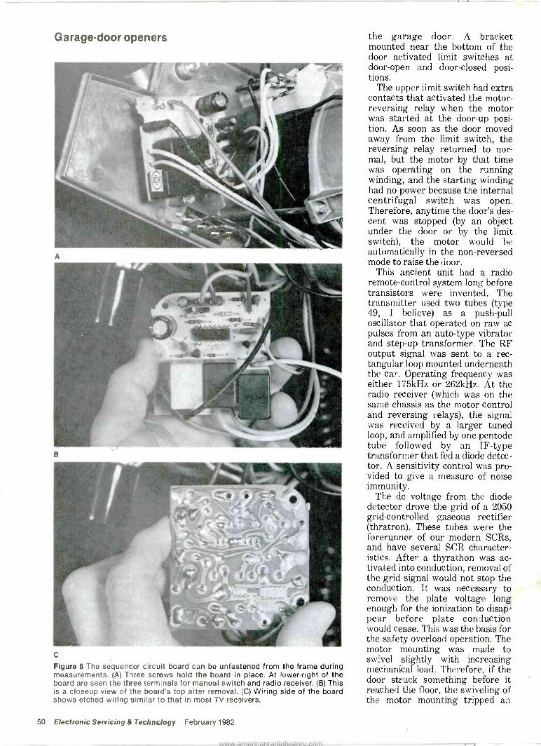
Garage -door openers
B
C
Figure 6 The sequencer circuit board can be unfastened from the frame during measurements. (A) Three screws hold the board in place. At lower -right of the board are seen the three terminals for manual switch and radio receiver. (B) This is a closeup view of the board's top alter removal. (C) Wiring side of the board shows etched wiring similar to that in most TV receivers.
the garage door. A bracket mounted near the bottom of the door activated limit switches at door -open and door -closed posi- tions.
The upper limit switch had extra contacts that activated the motor - reversing relay when the motor was started at the door -up posi- tion. As soon as the door moved away from the limit switch, the reversing relay returned to nor- mal, but the motor by that time was operating on the running winding, and the starting winding had no power because the internal centrifugal switch was open. Therefore, anytime the door's des- cent was stopped (by an object under the door or by the limit switch), the motor would be automatically in the non -reversed mode to raise the door.
This ancient unit had a radio remote -control system long before transistors were invented. The transmitter used two tubes (type 49, I believe) as a push-pull oscillator that operated on raw ac pulses from an auto -type vibrator and step-up transformer. The RF output signal was sent to a rec- tangular loop mounted underneath the car. Operating frequency was either 175kHz or 262kHz. At the radio receiver (which was on the same chassis as the motor control and reversing relays), the signal was received by a larger tuned loop, and amplified by one pentode tube followed by an IF -type transformer that fed a diode detec- tor. A sensitivity control was pro- vided to give a measure of noise immunity.
The do voltage from the diode detector drove the grid of a 2050 grid -controlled gaseous rectifier (thratron). These tubes were the forerunner of our modern SCRs, and have several SCR character- istics. After a thyrathon was ac- tivated into conduction, removal of the grid signal would not stop the conduction. It was necessary to remove the plate voltage long enough for the ionization to disap- pear before plate conduction would cease. This was the basis for the safety overload operation. The motor mounting was made to swivel slightly with increasing mechanical load. Therefore, if the door struck something before it reached the floor, the swiveling of the motor mounting tripped an
50 Electronic Servicing & Technology February 1982
www.americanradiohistory.com

FROM
LAMP
SWITCH 10K
16
+13
NOT CONWECTEDI
I I
15 14
+13 V FROM LIMIT
10K SWITCHES
+1 V FROM
OVERLOAD
10K - SWITCH
13 12 11
SEQUENCER IC
4 5 6
1
10 9
+0.7V X1 RELAY UP
+13 V
R12
4.7K
1.8K
Q1
+0.003 V
LIGHT Q3
X3 i
RELAY
+0.003 V
DOWN - X2 RELAY
Q2
120 VAC
+13 V FROM
MANUAL
10K SWITCH
+3.4V
1 0047 I § 220K
DI D2
>I >I +38 V
29 V RMS 100 µF 50 V
Figure 7 This schematic was developed by visual examination and meter measurements of the Genie model 450 sequencer unit. It is not a factory schematic. All voltages are assumed to be normal, except the + 0.7V
saturation bias at the 01 base, which appeared erratically because the IC was defective.
overload switch, which temporari- ly removed the positive do voltage from the plate. In the absence of a remote -control signal, the grid had cut-off bias, so the tube was de - ionized and it allowed the motor -on relay to open, stopping the motor.
Strangely enough, the old design performed identical functions and gave almost the same protection as provided by the much newer solid-state Genie.
The second requirement for suc- cessfully repairing any unfamiliar electronic' device is: You must know how to test the functions. The third requirement is related to the second: You must have proper
equipment and tools to make all needed tests accurately.
Comments Details of this troubleshooting -
and -repair case history are presented for two reasons. First, they give technicians some familiarity with the functions and circuits of electronically controlled garage -door openers, so they will not be reluctant to attempt similar repairs. Second, they show how a good general knowledge of elec- tronics can be used to troubleshoot almost any kind of machine.
One more comment: During almost seven months of constant
operation after the described repair, the Genie garage -door opener has performed perfectly.
If you have had a similar ex- perience troubleshooting electronic household ap- pliances, send a description to Electronic Servicing & Technology. Payment will be made upon publication.
February 1982 Electronic Servicing & Technology 51
www.americanradiohistory.com

Mt Each report about an item of electronic test equipment is based on examination and operation of the device in the Electronic Servicing and Technology laboratory. Personal observations about the perfor- mance and details of new and useful features are spotlighted, along with tips about using the equipment for best results.
By Carl Babcoke, CET
B&K-Precision 3020 sweep/function generator
Model 3020 is the center of B&K-Precision's line of six func- tion and pulse generators. Model 3020 (Figure 1) is a versatile in- strument that can perform most operations of a function generator, a sweep generator, a tone -burst generator and a pulse generator. Frequency (or repetition) rate of output signals spans 0.02Hz to 2MHz in seven ranges arranged in decades. The output frequency can be adjusted by the range -switch position vs. either adjustment of the front -panel calibrated vernier dial or a do control voltage applied to the proper phono input connec- tor on the back panel. This control voltage can be a non -varying do voltage, or it can be a do waveform. The voltage -controlled oscillator (VCO) allows many AM and FM functions.
A choice of three conventional output waveshapes (sine, square or triangle in Figure 2) is provided by push -buttons. These standard waveshapes can be modified by the symmetry variable control in nor- mal or inverted modes. For exam- ple, square waves become pulses, triangles become ramps (sawteeth) and sines are stretched and distorted.
The sweep mode enables rapid assessment of frequency response in amplifiers, tone controls, equalizers and tape recorders.
Tone -burst mode is useful for TIM tests, tone -burst decoder alignment and other audio measurements.
Figure 1 B&K-Precision model 3020 is a 2MHz sweep/function generator with many excellent features, including several functions usually accomplished by pulse generators, sweep generators, function generators and tone -burst generators.
FM and AM modulation can be obtained from internal or external signals.
A do offset voltage between + 5V, zero and - 5V is adjustable by a front -panel control.
Symmetry -control waveforms The three traces in Figure 3
show how the symmetry control changes square waves into pulses. At the symmetry control's CCW position, a detent holds the knob in calibrate position. As the sym- metry control is slowly rotated
L
"IrOVe A
c
Figure 3 When squarewaves are selected and the symmetry control is rotated CW from the calibration point, the cycles move farther apart (decreasing the repetition rate) to form pulses. The pulse width does not change from symmetry adjustments.
B
Figure 2 These are the three basic waveforms from model 3020. The top trace shows the waveform at 20Hz; the center trace at 1000Hz and the bottom trace at 2MHz. (A) Sine waves were good, except for a tiny pip at each peak of the low - frequency signals, and a slight rounding of the tips when the frequency was near 2MHz. (B) Some edge overshoot is evident in the low -frequency square waves, and slow rising and falling edges at 2MHz. (C) All triangular waveforms had excellent linearity, although the 2MHz triangles had some rounding of the peaks.
52 Electronic Servicing & Technology February 1982
www.americanradiohistory.com

clockwise, the square waves on the right begin to move to the right (as viewed on a scope) and become far- ther apart. Notice that the pulse width is not changed.
This action can be continued un- til the ratio of space to pulse width is about 40 -to -1. With this ratio, the pulses are so narrow that they are difficult to see on a scope screen. Ramps appear to have perfectly vertical rising edges. (Important: If the symmetry con- trol is rotated completely clockwise, no output signal is ob- tained. Therefore, always begin adjustments with the symmetry
control in its calibrate position.) All increases of space between
pulses of fixed width are decreases of the repetition rate. Therefore, any use of the symmetry control changes all calibrations of the fre- quency dial.
Remember that both pulse width and repetition rate are changed by adjustments of the range switch and the frequency dial, when the symmetry control is not at its calibrate position. However, rota- tion of the symmetry control varies the repetition rate but not the pulse width. Therefore, if a specific duty cycle or repetition
rate is needed, both the frequency and symmetry controls must be adjusted alternately until the desired conditions are shown on a scope.
Figures 4 (sine waveshape), 5 (pulse waveshape) and 6 (triangle waveshape) show a few of the many possible waveforms re- sulting from normal and inverted symmetry adjustments. These are compared with the TTL pulses coming from a phono jack on the rear panel.
Frequency -sweep mode Almost any section of the 2MHz
A B C
Figure 4 Top trace in each waveform photograph is the sinewave appearance under stated conditions, while each bottom trace shows the corresponding TTL waveform (that is available from a phono jack on the rear panel). (A) These are normal traces when the symmetry control is in the calibrate position. (B) CW rotation of the symmetry control produces a distorted ramp waveform. With this normal symmetry mode, the ramp rises to the right. (C) These are the same conditions as in B, but the symmetry has been inverted by the normal/invertion pushbutton. The ramp falls to the right. Notice that the TTL pulses did not invert with the signal waveform.
A B C
Figure 5 Top trace of each photograph is the modified squarewave appearance under stated conditions, while each bottom trace shows the corresponding TTL waveform. (A) The unmódified squarewave and the TTL pulses resemble each other. (B) CW rotation decreases the repetition rate. The TTL pulses (lower trace) change in step. (C) Changing the symmetry normal/invert switch to invert position inverted the pulses, making them positive -going (top trace), while the TTL pulses (bottom trace) were unchanged.
A B C
Figure 6 Top trace of each photograph is the appearance of triangular waveshapes under the stated conditions, and the bottom trace shows the corresponding TTL signal. (A) These are the normal triangular waveshapes with the symmetry con- trol in calibrate position. The TTL signal shows square waves. (B) CW rotation of the symmetry control changes the triangles to ramps. Continued CW rotation lengthened the up side and made the falling side more vertical. The TTL signal consists of pulses that are identical to those from pulses or sinewaves. (C) Changing the normal/invert switch to invert position inverted the ramps, but the TTL pulses were unchanged.
February 1982 Electronic Servicing & Technology 53
www.americanradiohistory.com

Test lab
range of output frequencies can be swept, provided the ratio of end frequencies does not exceed 1000 -to -1. A popular test is to measure frequency response of an audio amplifier between 20Hz and 20kHz (the maximum allowable 1000 -to -1 ratio).
Figure 7 shows an audio -sweep pattern with amplitude increases at 500Hz (at left) and 16kHz (at right). These level boosts were ob- tained by feeding the 3020 generator signal through a 10 - frequency audio equalizer. One of the difficulties is determining where the various frequencies are located on the waveform.
The same audio -sweep signal can be used for measuring equalization or adjusting bias levels in tape recorders.
Tone -burst tests Two examples of tone -burst ap-
plications are shown in Figure 8. Both are 1000Hz sinewave car- riers keyed into bursts. The first example shows a burst of about 4mS and a space between bursts of about 14.4mS. Notice that only whole cycles are generated. Cor- responding TTL pulses are shown by the bottom dual trace.
A much longer burst is pictured in Figure 8B. Approximately 84 sinewaves are produced. Therefore, the burst required 84mS. The top trace shows the output signal of a compressor when the compression was dis- abled, giving maximum gain. When compression was switched on, the gain was reduced in an ex- ponential curve (bottom trace). A gain reduction of about 6dB re- quired 16mS (16 cycles), which is typical of many audio com- pressors. A long burst was chosen to allow stabilization of the output level at the maximum gain reduc- tion (minimum output amplitude), and a longer space between bursts was needed to allow a return to maximum of the output amplitude (zero gain reduction).
AM and FM modulation Model 3020 can produce several
types of modulation, including amplitude modulation (Figure 9A), suppressed -carrier modulation (Figure 9B), and frequency modulation (Figure 9C).
ptio4iliii
1!q
Figure 7 This 20Hz to 20kHz audio -sweep pattern has increased amplitude at 500Hz and 16kHz, showing the action of a graphic equalizer with 8dB boost at 500Hz and 16kHz. A graphic equalizer can be used to calibrate audio sweeps. Log sweep was employed here to spread the low frequencies. These controls required adjustment to obtain audio sweep: sinewave pushbutton; frequency -range switch; frequency vernier dial; sweep -width control; sweep -rate control; burst -gate control; and Iinllog switch. The lower -trace ramp is the sweeping voltage scoped at the GCV output.
do offset voltage A do voltage can be mixed with
the output signal by adjustment of the do offset control. At minimum setting of the variable amplitude control, the offset control can pro- duce any voltage from about + 6V to - 6V when the output is loaded with a 50n load. Higher voltages can be obtained when the output has no external load resistor. With the amplitude control at max- imum, the range is between about + 4.5V and - 4.5V. These readings were obtained when the output at- tenuator switches were adjusted
for 0dB attenuation. When the at- tenuator switches are pushed, the reduction of output dc voltage is the same as the signal attenuation. In other words, a 10dB attenua- tion reduces the dc to about one third.
This feature is valuable for bias- ing a transistor while the generator also supplies the signal. The signal level and waveshape should be checked by a scope. The dc component can be tested by the scope, but a digital multimeter will give much higher accuracy.
Figure 10 shows how the dc and
Itl
tttt
III!I!I1I
A B
Figure 8 Two types of gated tone bursts are shown here. (A) A 1000Hz sinewave carrier is gated according to adjustments of the burst -gate and sweep -rate controls (top trace). The TTL output has a pulse for each sinewave cycle (bottom trace). (B) Gating the 1000Hz carrier at a much slower rate (tone is present for only about 84mS) produces a signal that is ideal for showing the action of an audio compressor. Top trace is the signal without compression. Normal compression is shown by the bottom trace.
54 Electronic Servicing & Technology February 1982
www.americanradiohistory.com

A B C
Figure 9 AM, suppressed -carrier AM, and FM modulation are possible with model 3020. (A) Internal high -frequency sinewaves are amplitude -modulated (AM) by a low -frequency sinewave from another generator. Percentage of modulation is adjustable. (B) By balancing out the carrier before the modulation is applied, the carrier is suppressed and only the positive -peak and negative -peak envelopes of carrier are present in the output signal. (C) Frequency modulation is shown by this waveform. The scope locks to one cycle, and the following cycles are moving sideways (varying frequency).
AvAvA
41111
A vir
A B
Figure 10 A steady dc voltage of either polarity can be added to the output signal by rotation of the
dc -offset control. When this feature is not needed, the control must be adjusted to center of rotation where a voltmeter measures zero voltage at the signal output. There is one possible complication if the variable amplitude control is rotated for maximum output level. (A) Top trace shows sinewave output with its zero -voltage line in the exact center. Notice that neither peak is clipped or rounded.
When the dc -offset control is rotated to produce about +3V at the output, the top of the waveform is clipped (bottom trace). This is a safety feature preventing damage to the generator, but it might give a false waveform and test results if the operator did not notice the clipped waveform. The dc -
offset control can be adjusted without a meter by scoping the output sine or triangle waveshape and rotating the dc -offset to where neither peak is clipped when the amplitude control is at maximum (full CW). (B) Clipping does not occur so easily when the level is reduced with the amplitude control. Top trace again shows zero dc voltage in the output signal, while the lower trace shows an unclipped sinewave above the zero line when the dc -offset control is adding about +3V to the reduced signal.
ac components are combined. There is one precaution: When full amplitude is required from the generator (amplitude control fully CW and attenuator switches without attenuation), adjustment of the dc -offset control must be checked. If it is producing anything other than OVdc, one peak of the signal will be clipped. This is particularly noticeable with sines and triangles.
Comments B&K-Precision model 3020 per-
formed all functions without any problems. Slight corner overshoot was noticed with squarewaves of some repetition rates. The rise and
fall times of squarewaves near the maximum 2MHz limit was some- what slow. However, it must be noted that the scope is rated at 35MHz, and 35MHz is only about the 17th harmonic of 2MHz - not enough to create good square - waves.
An excellent feature is the sym- metry control that changes squarewaves to pulses and triangles to ramps. Another ex- cellent feature is the audio -sweep mode that gives either log (for bet- ter view of low frequencies) or linear sweep. The setup for ob- taining audio sweep could be more convenient. The range and fre-
quency adjustments must be made to predetermined points, but then three variable controls must be painstakingly adjusted and read- justed to obtain the desired display.
TTL pulses for some functions and the AM or FM modulation modes are valuable features for specific types of testing.
Model 3020 sweep/function generator from B&K-Precision is an extremely versatile piece of test equipment that would be an asset for any audio or general elec- tronics shop.
ese February 1982 Electronic Servicing & Technology 55
www.americanradiohistory.com

Elmo Manufacturing entering a race of giants
By Joel A. Samberg
In the United States, there is no particular center of consumer elec- tronics marketing and manufacturing. Although a middle-sized, partially suburban community in New York's Nassau County seems an unlikely place for a strong surge of consumer elec- tronics there is one company that may put New Hyde Park firmly on that map. Elmo Manufacturing Corporation, a 57 -year -old photographic equipment company, has come out with its own version of the long -anticipated videodisc player developed by RCA and has recently released it to the market.
Elmo, with an employee roster at the Long Island facility of less than 100 (small compared to most other electronics manufacturers) is entering a videodisc race already heated with the presence of giants such as Zenith, Hitachi, Toshiba, Sanyo and, of course, RCA.
The company has a scheme, however, that may put its player ahead of the competition in one particular retail market. Elmo will sell its player almost exclusively through the camera stores and photographic equipment dealers that are already familiar and suc- cessful with the Elmo brand name, thereby instantly winning the sup- port of thousands of salespeople, managers and store owners across the country. Also, as one RCA ex-
ecutive points out, photographic salespeople are among the most professional and technically oriented retailers around and can do an extraordinary job of marketing the Elmo player.
Most electronics professionals not in the photographic retail business say, "Elmo who?" Elmo, which is an acronym taken from electricity, light, motion and organization, the basic ingredients of engineering, was founded by Hienobu Sakaki, a Japanese engineer. The company began manufacturing and marketing a slide projector that used a propeller -cooling mechanism designed by Sakaki. A line of still cameras came next, followed by motion picture projectors. After World War II, Sakaki established Elmo as a worldwide distributor of consumer and professional photographic equipment.
Among Elmo's current product lines are $35,000 theater projec- tors, 16mm portable projectors and top -of -the -line overhead pro- jectors. "We sell in excess of 15,000 to 20,000 overhead projec- tors to schools and institutions in the United States alone each year," said Vice President Vincent G. Marotti. An Elmo facility in Woodland Hills, CA, helps keep the supply in pace with the de- mand.
In 1980, Elmo had its team of
engineers examine a videodisc player to see how they could im- prove upon it.
"It was mostly done in conjunc- tion with Toshiba," Marotti ex- plained. "A great many of the com- ponents were manufactured by Toshiba, and our unit is very similar to theirs in appearance and performance."
RCA developed the Capacitance Electronic Disc format (CED), which Toshiba and Elmo are now using. Elmo executives selected the CED format because they feel it is the one most likely to dominate the videodisc market. One factor is support of that theory is that the CED format has more movie titles available than the laser format videodisc players manufactured by Magnavox and Pioneer.
RCA, which underwent a huge market introduction last spring, has such disc titles as Urban Cowboy, Ordinary People, Airplane, The Muppet Movie and several James Bond films. Some reports indicate, however, that it had not been entirely successful, apparently because RCA rushed into its introduction before the company an effec- tive test marketing campaign (though more recent reports in- dicate a steady gain in popularity).
What makes the Elmo player dif- ferent from the RCA is the addi- tion of a built-in stereo adapter jack and optional remote control. RCA expects to add stereo capability to its player within the next few years.
"I had several meetings with RCA when we first conceived the idea," says Marotti. "We basically discussed program distribution but they are fully aware that we're in the market with a compatible and competitive system. Their com- ments were very favorable. I think it just expanded their own disc horizons."
Arnold Valencia, president of RCA Sales Corporation, agreed. "It's an endorsement of the CED system," he said.
Though Valencia is not familiar with Elmo, he welcomes their par- ticipation. Both he and Marotti acknowledge that the photograph- ic and camera stores that have ventured into video have been sur- prisingly successful.
Personnel at two camera stores
56 Electronic Servicing & Technology February 1982
I www.americanradiohistory.com
on Long Island have somewhat dif- ferent perceptions of the disc machine's potential in camera stores. I & B Camera in Massape- qua is not an Elmo dealer, but Bob Larson, owner, said he thinks its disc player has a good chance.
"If they worked it out financially so that it would be profitable to my store, I'd carry it. After all, video is part of the photographic business."
Marlene Diller of Globe Audio Visual in Franklin Square, an Elmo dealer, contends that her customers don't seem to have a call for the videodisc. "Actually, we haven't gotten that involved in video to find out just what the market is"
But customers would not go to a photography store for a videodisc player if they didn't know it was sold there. The answer lies in advertising.
Elmo originally proposed a multi -million dollar advertising budget for the disc player but retreated when they saw RCA's trends. The budget is still enough for a major campaign, and Elmo's anticipation remains high.
"You don't enter into this sort of thing unless you have tremendous plans for it," said Murray Weinberg, Eastern sales manager.
Formerly in Woodside, Queens, Elmo Manufacturing Corporation moved to New Hyde Park in 1979 and continues to serve the sur- rounding communities by hiring local engineering and marketing personnel. Both Weinberg and Marotti speak highly of Long Island.
"If we expand," Marotti em- phasized, "We will expand in New Hyde Park. Manhattan and New Jersey (where many consumer electronics companies are located) would have to give us free rent to move there. We couldn't ask for a better facility. We have access to the highways, the railroad, the air- ports and the best choice of employees in the whole country."
If Elmo's videodisc player brings a whole new and lucrative career to the 57 -year -old company, its marketing and shipping depart- ments expect to need those transportation routes. The author is a freelance writer specializing in the arts and home entertainment.
as NEW! thelww td magazine of electronks...
Formerly
Electronic Servicing, ES&T is a new, exciting, bigger and better -than -ever magazine for the electronics of today and the future!
You will find Electronic Servicing & Technology must reading if you are to keep abreast of the rapidly changing technology in electronics, whether you are a professional technician or an avid hobbyist.
Every month you will receive your personal copy jam-packed with the information you need and want...information that will save you time and money...the most complete and up-to-date service data on audio and video equipment...information that will take you into the future of electronics...information you just can't afford to be without.
At a very low cost you'll explore the exciting new developments in Satellite TVRO; Microcomputers; Television; VideoTape and Cassette Recorders/Players; VideoDisc; Audio Products; Test Equipment; Ham, CB & Mobile RAdio; Robotics; Electronic Games, etc.
Nowhere else will you find such accurate and complete material. Charts, graphs, schematics and pictures generously supplement the easy -to -read and understandable text.
You would probably expect to pay much more for a magazine of this caliber, but right now you can take advantage of a special, limited - time subscription offer. Don't hesitate...subscribe now!
Detach and mail this convenient order form today
Please start my subscription to the new Elec- tronic Servicing & Technology right away. I
have enclosed my check, money order or VISA/MASTER CHARGE number for the amount indicated at right.
3 years $34.00 2 years $26.00 1 year $15.00
Please allow 6-8 weeks for delivery Name
Company
Address
City State
Signature
VISA`
ACCOUNT NUMBER
INTERBANK NUMBER
Zip
CHARGE TO MY: (Please check one)
2 MASTER CHARGE VISA
MASTER CHAR3c ONLY id ig;s of vv pur i,,mei
The n w o «wenn ecf.onres
ELECTiiCiiiC Sernvgókdrdogy
CARD EXPIRES
MO YR.
P.O. Box 12901 Overland Park, KS 66212
February 1982 Electronic Servicing & Technology 57
www.americanradiohistory.com
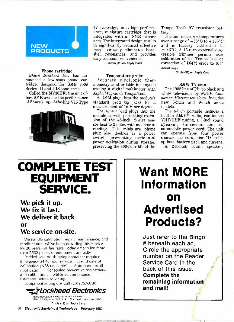
NEW PRODUCTS
Phono cartridge Shure Brothers Inc. has an-
nounced a low -mass phono car- tridge, designed for SME 3009 Series III and IIIS tone arms.
Called the MV3OHE, the unit of- fers SME owners the performance of Shure's top -of -the -line V15 Type
IV cartridge, in a high-perform- ance, miniature cartridge that is integrated with an SME carrier arm. The integrated design results in significantly reduced effective mass, virtually eliminates head - shell resonances, and provides easy -to -mount convenience.
Circle (31) on Reply Card
Temperature probe Accurate electronic ther-
mometry is affordable for anyone owning a digital multimeter with Alpha Magnum's Tempa Tool.
A DMM plugs into the module's standard prod tip jacks for a measurement of lmV per degree.
The sensor lead plugs into the module as well, permitting exten- sion of the 48 -inch, 2 -wire sen- sor lead to 2 miles with no error in reading. This miniature phone plug also doubles as a power switch, preventing accidental power activation during storage, preserving the 300 -hour life of the
COMPLETE TEST EQUIPMENT
SERVICE. We pick it up. We fix it fast. We deliver it back or We service on -site.
We handle calibration, repair, maintenance, and modification. We've been providing this service for 20 years-at fair rates. Today we service more than 7,500 pieces of equipment annually.
Padded van, no shipping container required.. Emergency 24-48 hour service... Certificate of calibration (NBS traceable)... Automatic recall notification... Scheduled preventive maintenance and calibration... Mil -Spec compliance.. .
Estimates before servicing. Equipment acting up? Call (201) 757-3730.
Lockheed Electronics Instrumentation Measurements Laboratory 1501 U.S. Highway 22 C.S. #1, Plainfield, New Jersey 07061
Circle (11) on Reply Card
58 Electronic Servicing & Technology February 1982
Tempa Tool's 9V transistor bat- tery.
The unit measures temperatures over a range of - 55°C to + 150°C and is factory calibrated to ± 0.3°C. A 15 -turn externally ac- cessible trimmer permits user calibration of the Tempa Tool or correction of DMM error to 0.1° accuracy.
Circle (32) on Reply Card
B&W TV sets The 1982 line of Philco black and
white televisions by N.A.P. Con- sumer Electronics Corp. includes new 5 -inch and 9 -inch ac -dc models.
The 5 -inch portable includes a built-in AM/FM radio, continuous VHF/UHF tuning, a 5 -inch round speaker, sunscreen and an automobile power cord. The unit can operate from four power sources: car cord, nine "D" cells, optional battery pack and current.
A 23/4 -inch round speaker,
Want MORE Information
on Advertised Products?
Just refer to the Bingo # beneath each ad. Circle the appropriate number on the Reader Service Card in the back of this issue. Complete the remaining information and mail!
www.americanradiohistory.com

ESR METER sunscreen and 70 -position click - stop UHF tuning are featured in the new walnut -grain plastic 9 -inch portable, which can operate via the included automobile power cord or an optional battery pack.
Circle (30) on Reply Card
TV projection system and cabinet
Edmund Scientific is offering a complete TV projection lens system and a cabinet to house it. The cabinet is constructed from flakeboard material with laminated walnut wood -grained finish. The unit is 14" x 21".
Designed for use with all 12 -inch to 15 -inch TV sets, it's the kind of do-it-yourself project that can be completed during a weekend.
In addition to the partially assembled cabinet, the TV projec- tion system includes a f/2.4 glass lens, a 45 -inch TV projection screen, lens focusing mount, wall brackets and an instruction manual.
Circle (15) on Reply Card
Satellite positioner Basic Systems has developed a
new control system for positioning TV satellite receiver dishes. The system consists of a telescoping actuator, a totally enclosed gear motor, a limit switch assembly and a coitrol panel that contains all of the indicators and controls for positioning receiver dishes up to 12 feet in diameter.
Designed for use on polar -type antenna 1pounts, the actuator, gear moto and limit switch are located at the antenna site, and the control panel ks wired into where the TV set is located. The control
box has a 3 -digit LED display that continuously shows relative anten- na position plus a red and a green indicator light to show when the actuator is at its upper and lower limits.
A memory reset push-button and yellow indicator light are also sup- plied to reset the display in the event of a power failure. Antenna position is controlled by a center - off -type rocker switch on the front panel.
Circle (16) on Reply Card
Microwave sweep generator Wavetek Indiana has announced
a new line of digital display gen- erators and has incorporated a number of innovations into a com- pact unit.
The model 1084 has three operating modes: CW, AF and full sweep. Frequency in the CW mode is set by a 10 -turn potentiometer and displayed with a resolution of 1MHz on a 31/2 -digit display. In the OF mode, center frequency is selected by the 10 -turn poten- tiometer; the range 500kHz to 1000MHz is controlled by a 100MHz/step selector and a 100MHz vernier. The model 1084 features 1% display linearity.
In the full sweep mode, the start frequency is 3.5GHz and the stop frequency is 4.5GHz. The 10 -turn potentiometer and 31/2 -digit frequency display operate as a variable marker. The marker produces a bright spot on the display by momentarily delaying the sweep ramp for approximately 2ps. Accuracy is ± 10MHz. Exter- nal marker input is standard.
Circle (17) on Reply Card
Keyless door lock Mountain West Alarm has an-
nounced a weatherproof push -
checks electrolytics IN -CIRCUIT and is TV shop
FIELD-TESTED: The most fantastic instrument I've ever bought-Billings, Mt. Used it 3 months; it only missed once- Marinette, Wis. (Typical). Squeal & no sync: 3 bad caps in B+ & AGC; Many Thanks-Taos, N.M. Please ship another; very satis- fied-Glen Rock, Pa. It's fantastic -St. Joseph, Mo. Please rush; heard good reports-Hicksville, N.Y. One tremendous meter- Alexandria, Minn. Send your Super meter; heard about it-N. Olmstead, Ohio. Love that ESR Meter-Acton, Mass. Used it in- tensively for 30 days; it's been 100% effective-Pittsburgh, Pa.
Ideal for preventive maintenance :
measures electrolyte dryness & shows up intermittent opens.
60 -day Satisfaction Guarantee. Send check or M.O. or call
(313) 435-8916 for COD Or write for free brochure to:
Creative electronics ESR Brochure $ 99.00
1417 N. Selfridge postpaid Clawson, Mich. 48017
USA & CAN.
Circle (5) on Reply Card
It's no puzzle to order Oelrich Service Forms For TV -radio and two-way radio service-
legal forms for Calif., Florida and Utah.
Now at parts jobbers or write for cat. B64.
OELRICH PUBLICATIONS 4040 N. Nashville Ave., Chicago, IL 60634
Now call toll -tree! 800-621.0105
Circle (6) on Reply Card
Your ad gets quick
results. Advertise
in classifieds.
February 1982 Electronic Servicing & Technology 61
www.americanradiohistory.com

button door lock. The lock eliminates the need for keys and locksmiths. Easy -to -install kit is practically pickproof and the com- bination is easily changed.
A weatherproof solid-state key- board resists vandals and has no moving parts to wear out or jam. System can also be programmed on the keyboard with a secondary combination to allow temporary access to neighbors and friends, similar to loaning key, without revealing master code. A tamper
alarm feature activates an elec- tronic tone and locks out the key- board for 25 seconds after 16 ran- dom numbers are pressed.
Circle (18) on Reply Card
Video still camera Sony Corporation has an-
nounced the development of a revolutionary video still camera, which uses the full advantages of advanced electronic technology in magnetic recording, CCD and IC semiconductors.
Called the MAVICA system, the new magnetic video still camera uses no photographic film and therefore does not require developing and printing processes, which are essential to conventional chemical photography.
Sony's MAVICA system replaces chemical processes with an electromagnetic system. The MAVICA is no larger than a con- ventional 35mm single-lens reflex camera. An image produced through the lens is converted into electronic signals by a solid-state imager called CCD (Charge Cou- pled Device), which was previously
developed by Sony. The signals are recorded on a very small magnetic disk that Sony has developed for the new camera system.
Circle (19) on Reply Card
Static -conductive soldering iron The Ungar Division of Eldon In-
dustries Inc., has introduced a
modular soldering iron that is elec- trically grounded from tip to plug connection to prevent static elec- tricity damage to microcircuits.
Three wattages and tempera- ture ranges are available: Ungar 1270, 27W, 650-750°F; Ungar 1350, 35W, 750-850°F; and Ungar 1450, 45W, 900-1000°F.
All models have thermoplastic "soft -touch grips" and handles are balanced to reduce worker fatigue and resistant to fluxes and acids.
Circle (20) on Reply Card
VCR accessory rack Channel Master's counter -top,
revolving VCR accessory rack displays up to 150 items, and is free with model 0700 VCR Ac- cessory Display Package. The 32 -inch -tall rack features a com- pact turning radius of 24 inches and is now available from Channel Master distributors.
VCR equipment and accessory
items included in the package are: 7511 and 300e matching transformers, band separators, VCR band separators, 2- and 4 -set U/V/FM couplers, 2 -way and 4 -way line splitters, single channel joiners, baluns and 7511 cable and connector kits and switches.
Circle (21) on Reply Card
Display and minicomputer New electronics from the John
Fluke Manufacturing Company Inc. allow people to interact with machinery, information systems, filing systems, instruments, inven- tory, process control, orders, cash machines and numerical control systems just by touching a display screen. The 1780A Infotouch Display is a special display screen with a touch sensitive overlay. Messages, numbers, graphics, menus, switches and special characters can be displayed through computer programming to guide an operator's response
step by step. Almost any desktop computer, home computer, minicomputer or large computer system can use the 1780A as a man -machine interface.
The 1720A is a minicomputer with many diverse applications from controlling automated manufacturing to monitoring medical instruments.
Circle (22) on Reply Card
Erasable circuit building A P Products Inc. Super -Strips
allow you to build a circuit almost as fast as you can dream one up. They combine a power/signal distribution system with a matrix of 128 terminals, each with five tie points. The distribution system has eight different buäés, with each individual bus coniprised of a line of 25 tie points. All tie points are the solderless plu -in type that have been pioneered by A P Prod- ucts.
62 Electronic Servicing & Technology February 1982
www.americanradiohistory.com

Super -Strips will accommodate up to nine 14 -pin DIPs and are compatible with all DIPs and discretes with lead diameters to 0.032 inches. The distribution system features a universal 0.1" x 0.1" matrix and requires no special patch cords. Any solid wire up to no. 20 A.W.G. can be used for in- terconnections.
Circle (23) on Reply Card
Electronics soldering course The PACE Inc. Basic Soldering
Course in Electronics is now available in 11 languages.
The course is a widely used training program to instruct beginners and upgrade the skills of experienced personnel in perform- ing high reliability soldering.
The films are available in French, German, Italian, Spanish, Mandarin Chinese, New People's Republic Chinese, Norwegian, Swedish, Dutch, Hebrew and Por- tuguese.
The course is a comprehensive, in-depth training program intend-
ed primarily for classroom use by an instructor. The films in multilanguage forms can be easily integrated into training programs nearly anywhere in the world.
Circle (24) on Reply Card
Video switching consoles Marshall Electronics Inc. has an-
nounced a netw series of video
switching control consoles de- signed for home video systems. All of the units feature high isolation and low loss.
The series includes three RF (VHF/UHF) switching consoles and one direct audio/video switcher.
The MCC -500 is a 5 -way high isolation RF switch that can pass signals in any direction. The MCC -500 can provide control of five program sources to a televi- sion or video recorder or can send one signal to five selectable loca-
tions. Unique vertical mounting of the switches prevents cable and cabinet movement during program selection.
Circle (25) on Reply Card
Video selector Winegard Company, manufac-
turer of TV system equipment, has introduced a second generation video selector, model VS -4002.
The Winegard VS -4002 features simple slide switches that allow the viewer to watch, record, edit and monitor programming without connecting or disconnecting cables.
Four 75 st inputs will accept any combination of the following: cable television, outdoor antenna, over - the -air pay television (STV, MDS), VCR, video disc, video games,
Now, more than ever ...Men who KNOW say...
IS THE ANSWER
HELP NATESA HELP YOU
BY DOING YOUR PART
Are YOU the operator of an
ethical, professional caliber tv -
radio -home electr3nics service
business?
Write for details on how you can
gain great benefits and participate in the destinies of this great
industry.
NATESA 5930 S. Pulaski Road
Chicago, Illinois 60629
FREE CATALOG Burglar/Fire Alarms
Controls Wireless Components Ultrasonic \licit cs;nc In-
frared* Sirens Bells CC'l'\' I airks Safes Dire Ss stems
` Mountain West Dept. ES -2
4215 N. 16th St. Phoenix, Ariz. 85016 8011-528-6169
Circle (7) on Reply Card
Want MORE Information
on Advertised Products?
Just refer to the Bingo # beneath each ad. Circle the appropriate number on the Reader Service Card in the back of this issue. Complete the remaining information and mail!
February 1982 Electronic Servicing & Technology 63
www.americanradiohistory.com

earth station, computer terminals. Dow Jones wire service and more.
Circle (26) on Reply Card
Outlet strips Five new industrial models of
Sockets Plus multiple outlet strips for assembly line and test stations and similar applications have been
introduced by Perma Power Elec- tronics Inc.
The new industrial strips are 2-, 4-, and 6 -feet long, and provide up to 24 outlets for plugging in tools, test instruments and appliances. Each is protected by a circuit breaker and is available with either a 6- or 12 -foot, double - insulated, 14 -gauge power cord.
You could be making extra cash...' ...and have the personal satisfaction and prestige of having your work published in a national magazine.
Electronic Servicing & Technology, the new magazine for the electronics of today and the future is in need of technical servicing articles on audio and video consumer electronic products.
As a professional electronics technician, you could be mak- ing extra cash by submitting articles for publication to ES&T. You may think, "I know my stuff, but I'm no writer."
No problem. Our expert staff will polish your original material and
graphics into a finished product with your byline. This is your opportunity to earn extra money, and also
benefit your fellow technicians with your own expertise. For more details, write or call:
DO IT NOW!
Bill Rhodes Editorial Director Electronic Servicing & Technology P.O. Box 12901 Overland Park, KS 66212 (913) 888-4664
All units are UL listed, and all have a master switch and indicator light.
Circle (27) on Reply Card
Waveform analyzer Sencore has introduced the
model SC61 waveform analyzer. The SC61 fully integrates a digital readout with the waveform analyz- ing capability of a high perfor- mance oscilloscope.
Unlike "piggyback" scope/DVM combination units, the SC61 makes all measurements through one probe, including digital readout of do volts, peak -to -peak volts (patent applied for), frequen- cy (patent applied for) and time. The single probe not only
eliminates the loading experienced when you hook up more than one probe to a test point, but speeds every measurement as it eliminates the need to connect and disconnect other instruments.
Circle (28) on Reply Card
Service kit Vaco Products Company's no.
4900-63 solderless terminal service kit contains 20 of the most popular insulated terminal styles with more than 400 terminals in all, plus the no. 1963 wiring and crimping tool, which crimps ter -
64 Electronic Servicing & Technology February 1982
www.americanradiohistory.com

minais, cut and strips wire, and slices bolts.
The various terminal styles are packed separately in individual bags, then placed in their own compartments keeping the assort- ment neatly organized. And an identification chart on the side cover illustrates and describes each terminal style, making it easy for the user to identify and select the proper terminal needed for the job.
Circle (29) on Reply Card
Insulation resistance tester Universal Enterprise's IRT1000
is a versatile, three -range (2Msz ranges: 0-100M st and 0-1000Mo; 1st range: 0-100x2 ,
4 ft mid scale) insulation resistance
tester for shop and field use. The IRT1000 can be used for testing electrical machinery, hermetic compressors, transformers, switch blocks, electronic components and cables.
Features of the IRT1000 include battery operation for complete portability, solid-state circuitry, automatic zero adjust, internal electronic voltage regulator (no - drift reading), color -coded meter face, battery check feature, automatic circuit discharge, and fuse protection on all ranges. The IRT1000 comes with tilt -stand car- rying case, batteries, data cards, test leads, instructions and a one- year warranty.
Circle (39) on Reply Card
Desoldering pump A desoldering pump that can be
operated with one hand and without external power has been introduced by the Ungar Division of Eldon Industries.
A spring -loaded piston creates a vacuum that instantly removes molten solder. Double 0 -ring piston seals achieve maximum vacuum in a piston stroke of less than 2 inches. The piston is set with the thumb and released by push-button for maximum spring force. The worker's other hand is left free to hold the soldering iron that melts the solder.
The Ungar 7874 vacuum desoldering pump is made of anodized aluminum and includes a self-cleaning, no -clog Teflon tip that is replaceable (part no. 7875).
Circle (40) on Reply Card
Protective cover PPS of Santa Fe Springs, CA,
has announced the introduction of their G -line of protective vinyl covers for home electronic games.
The G -line protective covers are light, easy to store and protect the unit from scratching and fading while enhancing the beauty of the unit.
All G -line models feature a unique cable cut-out that makes them compatible with the Atari, Mattel, Magnavox and Sears elec- tronic games.
Circle (42) on Reply Card
ESA'
SAVE TIME For fast, accurate service, please remove the Peel -Off Label (which is used to address your magazine) and affix it to the Reader Service Card, the Address Change Card, or to any correspondence you send us regarding your subscription.
NATIONAL ELECTRONIC
NESDA SERVICE DEALERS ASSOCIATION. INC
itEY to SUCCESS
NESDA OFFERS
I A National Certification Program ! National Recognition
Government Representation $ Business Contacts
Purchase Discounts l Low Bankcard Rates
1 Educational Materials $ Industry and Business Information
Pf -us I A Subscription to "ServiceShop"
Magazine and Yearbook
Please send more information about:
NESDA, 2708 West Berry St. Ft. Worth, TX 76129
name
address
city state zip
business
February 1982 Electronic Servicing & Technology 65
www.americanradiohistory.com
ATTENTION
TECHNICIANS
* JOB OPENINGS
* MONTHLY TECHNICAL
TRAINING PROGRAM
* BUSINESS MANAGEMENT
TRAINING
* LOW COST INSURANCE
* CERTIFICATION
* TECHNICAL SEMINARS
All of this in a nonprofit international association for technicians
FIND OUT MORE:
XII I OM : ETA \l ,/%
R.R. 3 Box 564 Greencastle, IN 46135
L J
ES&T
classified
ads
are well-read.
Use them at a
low-cost
insertion.
NEW LITERATURE
A 12 -page, 4 -color brochure ex- plaining the services offered to dealers, distributors, manufac- turers and the consumer by the Satellite Services Bureau is of- fered free by the organization. The text explains the purchasing con- sortium concept where dealers may purchase products at attrac- tive discounts as well as a list of six other services including lead generation, promotional assist- ance, information updates, management training programs, business counsel and a code of pro- fessional practice. Also included is the bureau staff and a membership application form.
Circle (45) on Reply Card
Leader Instruments Corpora- tion has announced the availability of their 1982 catalog. The 48 -page, comprehensive catalog includes detailed descriptions, specifica- tions, photographs and pertinent charts and illustrations of more than 70 products, including oscilloscopes, frequency counters, digital multimeters, function generators and video and audio test instruments.
Announced in the new catalog
LEADER Instruments Corporation
are 10 new products with unique capabilities. A vectorscope with CRT -generated vector targets, an X -Y display module that can be precisely customized to OEM user needs and requirements, and a CRT display designed for use in microwave swept frequency measurements are included.
Circle (46) on Reply Card
Publication of a detailed, 16 -page catalog on Sylvania brand ECG flameproof resistors has been
announced by the Special Markets Philips ECG Inc.
Entitled The Complete Line, this catalog lists the characteristics of more than 1000 individual ECG types, ranging in power handling capability from 1/4W to 25W, with resistance values from 0.1 st to 100Ma
Sylvania brand ECG flameproof resistors can be used to replace carbon composition, carbon film, metal film, cermet film, wire - wound and fuse resistors.
Circle (47) on Reply Card
Distributor & Division of
TRW Power Semiconductors has published a comprehensive cross-reference list of industry and TRW part numbers.
The new 8 -page, 2 -color publica- tion contains more than 1,900 en- tries, showing EIA numbers in conventional order and the cor- responding TRW numbert
Circle (56) on Reply Card
CES &f N
66 Electronic Servicing & Technology February 1982
www.americanradiohistory.com
BROADMOOR 3619, 8019 2040-1
BOHSEI Chassis M9C3-5B1, B3 2042-1
JCPenney 685-1020F, -00 (855-2879) 2040-2 685-1037E, -00, 6875-1037F, -10 2041-1 685-1034F, -10 2042-2 685-2008F, -00, 685-2053F, -00 2043-1
MGA BB -1242/270 2044-1
PANASONIC TR-1214T/15T 2041-2 TR -5040P/41 P 2042-3 Chassis NMX-K7A 2043-2 CT -9000/010/020/030 2046-1
QUASAR Chassis ALDTS/LDTS/YALDTS-989 2045-1
RCA Chassis KCS205CA 2046-2
SHARP FF19661, 19F86 2046-3 FF13601, 13F22 2045-2
SONY Chassis SCC-352A-A 2040-3 Chassis SCC-350A-A 2041-3 Chassis SCC-341A-A 2044-2
WARDS GEN -11950A 2044-3 GEN 11120A 2045-3
GET COMPLETE DETAILS about the products
advertised or described In this Issue.
Use Free Inquiry Card.
CUSTOMER ENGINEERS Discover The Career
Challenge And Prestige Which Only Cray Can Offer!
Working with one of the world's fastest supercomputers offers challenge and prestige unmatched anywhere. Ifs what you can experience as a customer engineer with Cray Research, developer of the Cray -1, an advanced super- computer, capable of producing up to 240 million floating point operations per second.
Customer engineering positions now exist with Cray in the Great Lakes, Southeastern and Southwestern sec- tions of the U.S. offering individuals unique opportunities for hands-on work with state-of-the-art, high-technology computers.
Servicing the Cray computer at on - site customer locations requires individ- uals with 1-3 years on -site experience in dealing with large-scale or digital computers. An associate technical de- gree is helpful, and a thorough, in- house training program will be provided to qualified candidates.
If you feel it's time your experience earned you more than a job, consider a career backed with the challenge and prestige which only Cray can offer. To find out more, including informa- tion on our excellent company benefits and competitive salaries, please send your resume in confidence to:
RESEARCH, INC.
John F. Borchers Department 201 CRAY RESEARCH INC. 1440 Northland Drive St. Paul, MN 55120
Equal Opportunity Employer M/F/H/V
Circle (10) on Reply Card
February 1982 Electronic Servicing & Technology 67
www.americanradiohistory.com

THE MARKETPLACE
Advertising rates in the Classified Section are 50 cents per word, each insertion, and must be accom- panied by cash to insure publication.
Each initial or abbreviation counts a full word.
Minimum classified charge $10.00.
For ads on which replies are sent to us for forwarding (blind ads), there is an additional charge of $3.00 per insertion to cover department number, processing of replies, and mailing costs.
Classified columns are not open to advertising of any products regularly produced by manufacturers unless used and no longer owned by the manufacturer or distributor.
For Sale
THE GREAT ELECTRONIC I THINGS & IDEAS
HUNDREDS OF UNUSUAL PARTS, GADGETS & IDEA ITEMS, UNAVAILABLE IN STORES OR CATALOGS ANYWHERE, Barga,n pnces on everyth,ng' New .terns In every issue, Rush postcard for your copy'
©©M ELECTRONICS Dept. 311 Plattsburgh, N.Y. 12901.'
Circle (8) on Reply Card
AUTOMOBILE RADIO and tape replacement parts: Delco, Chrysler, Philco-Ford, Motorola, Panasonic and many others. Large inventory. Laran Electronics, Inc., 3768 Boston Road, Bronx, NY 10469. (212) 881-9600, out of New York State (808) 223-8314. 5-79-tf
TV & RADIO TUBES, 36 cents EA!! Free color catalog. Cornell, 4221 University, San Diego, California 92104.
8-76-tf
ELECTRONIC SURPLUS: CLOSEOUTS, LIQUIDA- TIONS! Parts, equipment stereo, industrial, educa- tional. Amazing values! Fascinating items unavailable in stores or catalogs anywhere. Unusual FREE catalog ETCO-011, Box 762, Plattsburgh, N.Y. 12901. 6 -78 -If
SCRAMBLED TELEVISION, encoding/decoding. New book. Theory/circuits. $9.95 plus $1 shipping. Workshop, Box 393ES, Dept. E, Bethpage, N.Y. 11714.
7-80-t f
PRINTED CIRCUIT boards from your sketch or art- work. Affordable prices. Also fun kit projects. Free details. DANOCINTHS INC. Dept. ES, Box 261, Westland, Ml 48185. 5-81-tfn
TUBES FOR TV AND RADIO -35¢ ea. Washington TV Service, 1330 E. Florence Ave., Los Angeles, CA 90001.
10-81-5t
PICTURE TUBE REBUILDING EQUIPMENT capable of producing four high quality tubes per day (WILL TRAIN TO OPERATE). Call or Write Atoll Television, 6425 Irving Park, Chicago, Illinois 60634, ph. 312-545.6667. 10-81-6t
RADIO-TV TUBES INCLUDING ANTIQUES! Many tubes thought to be obsolete are still being manufac- tured. Write for free discount price sheet of over 1,800 types. Electronic Parts Co., 1015 S. Escondido Blvd., Escondido, CAL 92025, (714) 741-2300. 1-82-6t
FOR SALE (Cont.)
FOR SALE: SAMS PHOTOFACTS FOLDERS 100 to 910 plus, $1.00 each, plus shipping. Bordan's, 1781 Aurora Rd., Melbourne, Florida (305) 259-2146. 2-82-1t
FOR SALE-MINISCOPE NLS M5215 with Probes. Ex- cellent Condition $250.00. Al Rose, 650 Daphne St., Broomfield, CO 80020. 2-82-1t
FOR SALE: SENCORE VA48, nearly new, best offer over $600. Frank Knight, RFD 1, Box 675, New Gloucester, Maine 04260, (207) 926-3323. 2-82-1 t
Business Opportunity
TV TECHNICIAN! Increase your income up to $60,000 yearly. Rent -lease -sell TVs new -used, even from com- fort of your home. Basic Preliminaries $4.00. Perrys TV Systems, 1467 Hwy. 90 West, Milton, FL 32570, 904-994-0068
12-81-tf
COMPUTERIZE YOUR ENTIRE TV OPERATION. GL- AP-AR-INV. Tubes-Parts-Customer-Vendor & TV rental files -programs. Start small & add to later. For Apple TRS80-NEC-Heath-Zenith- Free details. Perrys Computer Systems, 1467 Hwy 90 West, Milton, FL 32570.904-994-0068. 11-81-tf
FLORIDA'S WEST COAST: Small T.V. Service Business attached to home; plus separate rental house. Have CERTIFIED APPRAISAL. Ph. 1-813-541-2039 or write: Owner, 7744 - 46 Ave. North, St. Petersburg, Fla. 33709. 1-82-tfn
SOUTH FLORIDA TV SERVICE business for sale. Established same location over 20 years. Buy inven- tory and phone number and move right in. P.O. Box 159, Boynton Beach, Fl. 33435. (305) 734-6121. 2-82-2t
Help Wanted
TV and 2 -way Technicians wanted. $15K to $22K per year. Benefits include employee stock purchase plan, In the largest Retail Service Center in Northwest Kan- sas. Friendly community, good schools, short drive to the Rockies. Equal Opportunity Employer. Miller's Electronics Inc., Goodland, KS 67735.913-899.2386.
10-81-tf n
HIGHEST EARNINGS AVAILABLE to top-notch TV technicians. Must be totally honest, non-smoker, non- drinker. Low crime area. Excellent for families. Superior camping, hunting, boating, fishing and skiing area. Send resume and recent snapshot to American Television Service, 1032 South State St., Orem, UT 84057 (801-226-1776). 2-82-1t
Support the
March of Dimes BIRTH DEFECTS FOUNDATION
THIS SPACE CONTRIBUTED BY THE PUBLISHER
ADVERTISERS' INDEX
Reader Service Number
Page
Number
9 B&K Precision 13
10 Cray Research 67
5 Creative Electronics 61
ETA 66
8 ETCO 68
2 Keithley Instruments Div. 1
7 Mountain West Alarm Supply 63
1 NAP/Philips ECG IFC
NATESA 63
NESDA 65
6 Oelrich Publications 61
4 PTS Corp. 11
Sencore, Inc. BC
3 A. W. Sperry Instruments Inc. 7
Tektronix, Inc. 5
ELGOTROAIO Servicing &Technology
Advertising Sales offices NATIONAL SALES MANAGER Greg Garrison P.O- Box 12901 Overland Park, KS 66212 Phone: (913) 888-4664
LONDON, ENGLAND John Ashcraft & Co., John Ashcraft 12 Bear Street, Leicester Square London WC2H 7AS, England Phone: 930-0525 Telex: 895-2387
AMSTERDAM, Holland John Ashcraft & Co. John J. Lucassen Akerdijk 150A 1171 PV-Badhoevedorp, Holland Phone: O.2968-6226 Telex: 18406 HARKE NL
TOKYO, JAPAN International Media Representatives, Ltd. Sumio Oka 2-29, Toranomon 1-chome Minato-ku, Tokyo 105, Japan Phone:502-0656
NORWOOD, AUSTRALIA Williamson & Associates Pty- Ltd. P.O. Box 419 Norwood S.A. 5067, Australia Phone: 42-7074
TAIPEI, TAIWAN. R.O.C. Antony Liu Long Life Advertisement Agency Co. P.O. Box 17-134 Taipei, Taiwan- R.O.C. Telephone: (02) 561-6629 Cable: Photop Taipei
68 Electronic Servicing & Technology February 1982
www.americanradiohistory.com

For the man that would rather fix it himself
Technical Publications has service manuals designed for you! SES -13 Small (Air Cooled) Engines Service Manual. $9.95 (336 pages). You can service your own engines on lawnmowers, tractor sprayers and other power equip- ment. Special section on fundamentals, troubleshooting, preventive maintenance. Step-by-step instructions. WLMS-1 Walking Lawnmower Service Manual $7.95 (128 pages). The complete guide to the care and repair of your walk -behind, push -type lawnmower. Exploded views and diagrams.
CSS-6 Chain Saw Service Manual. $8.95 (over 300 pages). Here's everything you need to know to tear down, repair, reassemble and adjust most popular chain saws. A truly complete chain saw manual.
GSM -1 Small AC Generator Service Manual $7.95. A brand new manual that contains maintenance, service and troubleshooting procedures, as well as wiring schematics for most generator models. Covers electrical powerplants under 8kW that generate alternating current and are driven by air cooled engines.
OS1-8 Outboard Motor Service Manual Volume 1 $8.95 (236 pages). Covers motors below 30 hp.
0S2-8 Outboard Motor Service Manual Volume 2 $8.95 (232 pages). Covers motors with 30 hp and above. Both Volumes 1 and 2 provide detailed fundamentals on periodic servicing.
Put these books to work on your own equipment...(Or service outside equipment for profit!)
Small (Air Cooled) Engines Service Manual Walking Lawnmower Service Manual Chain Saw Service Manual Small AC Generator Service Manual Outboard Motor Service Manual (Vol. 1)
Outboard Motor Service Manual (Vol. 2)
Remittance must accompany orders of less than $25.00. Postage paid when payment accompanies order. Allow four weeks for delivery.
How to send money: The best way to send money is your own personal check, post office money order, express money order or by bank draft or check. DO NOT SEND CUR- RENCY OR STAMPS.
Check Money Order Enclosed Ship C.O.D. (No C.O.D.s outside of U.S.)
Missouri and Kansas Residents add 4% sales tax. Tennessee Residents add 6% sales tax.
Write for a free catalog covering our entire line of service manuals and wheel -type tractor service manuals.
VISA MASTERCHARGE Credit Card Number Expiration Date
Please Print:
Name
Street
City
State Zip
Signature
Technical Publications Division Intertec Publishing Corp. P.O. Box 12901, Dept. ES Overland Park, KS 66212 (913) 888.4664
L ---------------------------- I
www.americanradiohistory.com
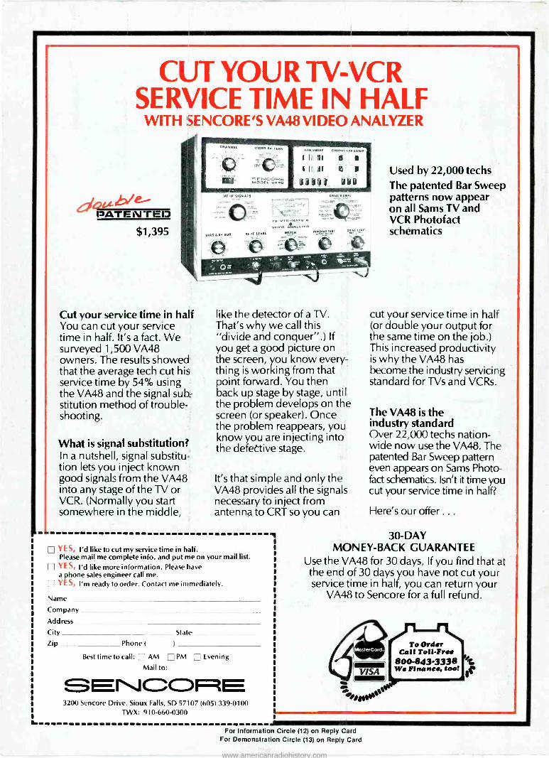
CUT YOUR TV -VCR SERVICE TIME IN HALF
WITH SENCORE'S VA48 VIDEO ANALYZER
d4£ PATENTED $1,395
Cut your service time in half You can cut your service time in half. It's a fact. We surveyed 1,500 VA48 owners. The results showed that the average tech cut his service time by 54% using the VA48 and the signal sub- stitution method of trouble- shooting.
What is signal substitution? In a nutshell, signal substitu- tion lets you inject known good signals from the VA48 into any stage of the TV or VCR. (Normally you start somewhere in the middle,
like the detector of a W. That's why we call this "divide and conquer".) If you get a good picture on the screen, you know every- thing is working from that point forward. You then back up stage by stage, until the problem develops on the screen (or speaker). Once the problem reappears, you know you are injecting into the defective stage.
It's that simple and only the VA48 provides all the signals necessary to inject from antenna to CRT so you can
YES, I'd like to cut my service time in half. Please mail me complete info, and put me on your mail list. YES, I'd like more information. Please have a phone sales engineer call me. YES, I'm ready to order. Contact me immediately.
Name
Company
Address
City
Zip Phone (
State
Rest time to call: AM J PM [J Evening
Mail to:
NCO -- E 3200 Sencore Drive. Sioux Falls, SD 57107 (605) 339-0100
TWX: 910-660-0300
Z
Used by 22,000 techs The patented Bar Sweep patterns now appear on all Sams TV and VCR Photofad schematics
cut your service time in half (or double your output for the same time on the job.) This increased productivity is why the VA48 has become the industry servicing standard for TVs and VCRs.
The VA48 is the industry standard Over 22,000 techs nation- wide now use the VA48. The patented Bar Sweep pattern even appears on Sams Photo.. fact schematics. Isn't it time you cut your service time in half?
Here's our offer...
30 -DAY MONEY -BACK GUARANTEE
Use the VA48 for 30 days. If you find that at the end of 30 days you have not cut your service time in half, you can return your
VA48 to Sencore for a full refund.
MasterCard.
VISA
To Order Call Toll -Free
800-843-3338 We Finance, tool se
a. For Information Circle (12) on Reply Card
For Demonstration Circle (13) on Reply Card
www.americanradiohistory.com


