Servos. The material presented is taken from a variety of sources including: http://www.seattlerobotics.org/guide/servos.html , http://www.baldor.com/pdf/manuals/1205-394.pdf , and Parallax educational materials. Overview. - PowerPoint PPT Presentation
Servos The material presented is taken from a variety of sources including: http://www.seattlerobotics.org/guide/servos.ht ml , http://www.baldor.com/pdf/manuals/1205-394.pdf , and Parallax educational materials
Transcript
Servos
The material presented is taken from a variety of sources including:
http://www.seattlerobotics.org/guide/servos.html, http://www.baldor.com/pdf/manuals/1205-394.pdf, and
Parallax educational materials
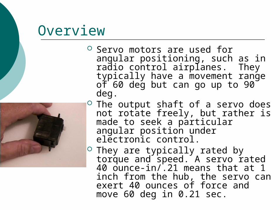
Overview Servo motors are used for angular
positioning, such as in radio control airplanes. They typically have a movement range of 60 deg but can go up to 90 deg.
The output shaft of a servo does not rotate freely, but rather is made to seek a particular angular position under electronic control.
They are typically rated by torque and speed. A servo rated 40 ounce-in/.21 means that at 1 inch from the hub, the servo can exert 40 ounces of force and move 60 deg in 0.21 sec.
What makes a Servo
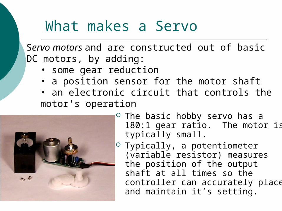
The basic hobby servo has a 180:1 gear ratio. The motor is typically small.
Typically, a potentiometer (variable resistor) measures the position of the output shaft at all times so the controller can accurately place and maintain it’s setting.
Servo motors and are constructed out of basic DC motors, by adding:
• some gear reduction• a position sensor for the motor shaft• an electronic circuit that controls the motor's operation
Feed-back loop
open-loop
closed-loop
Control An external controller (such as the
Basic Stamp) tells the servo where to go with a signal know as pulse proportional modulation (PPM) or pulse code modulation (which is often confused with pulse width modulation, PWM).
PPM uses 1 to 2ms out of a 20ms time period to encode its information.
PPM
A control wire communicates the desired angular movement. The angle is determined by the duration of the pulse applied to the control wire.
The servo expects to see a pulse every 20 milliseconds (.02 seconds). The length of the pulse will determine how far the motor turns. A 1.5 millisecond pulse will make the motor turn to the 90 degree position (often called the neutral position).
If the pulse is shorter than 1.5 ms, then the motor will turn the shaft to closer to 0 degrees. If the pulse is longer than 1.5ms, the shaft turns closer to 180 degrees.
PPM
PPM
The amount of power applied to the motor is proportional to the distance it needs to travel. So, if the shaft needs to turn a large distance, the motor will run at full speed. If it needs to turn only a small amount, the motor will run at a slower speed.
Modified Servos
Servo motors can also be retrofitted to provide continuous rotation: Remove mechanical limit (revert back to DC
motor shaft). Remove pot position sensor (no need to tell
position) and replace it with 2 equal-valued resistors with a combined resistance equivalent to that of the pot. This makes the servo “think” it is in the 90 deg position.
Not always necessary
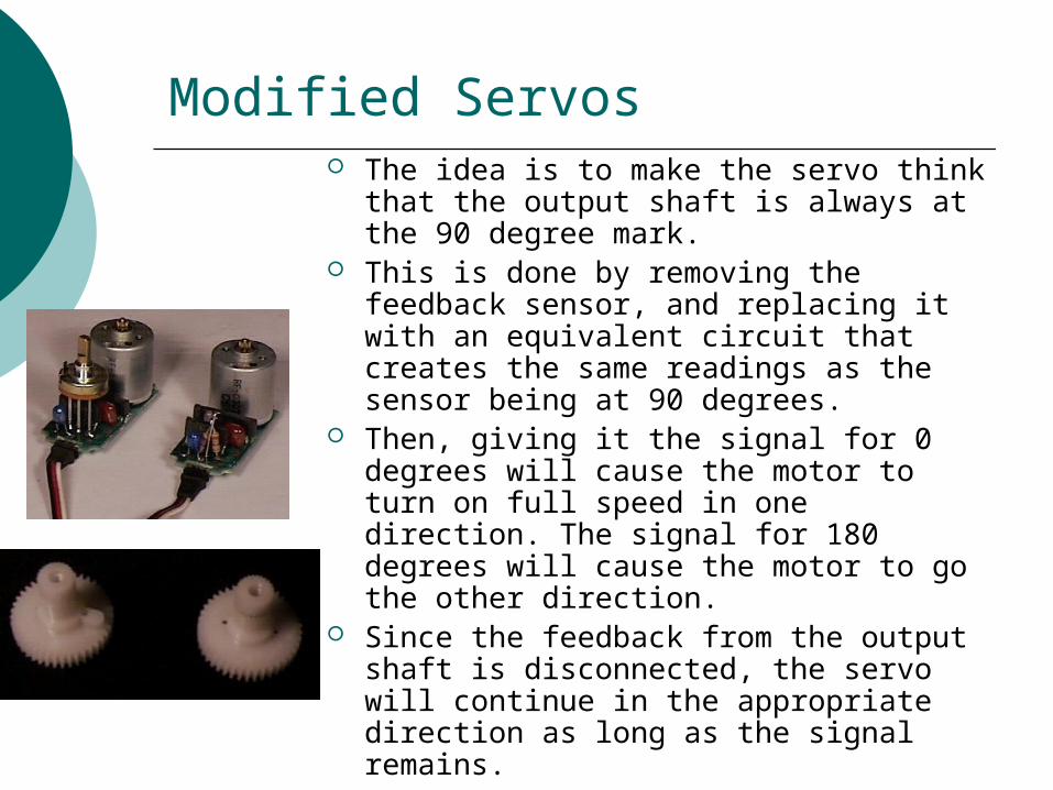
Modified Servos The idea is to make the servo think that
the output shaft is always at the 90 degree mark.
This is done by removing the feedback sensor, and replacing it with an equivalent circuit that creates the same readings as the sensor being at 90 degrees.
Then, giving it the signal for 0 degrees will cause the motor to turn on full speed in one direction. The signal for 180 degrees will cause the motor to go the other direction.
Since the feedback from the output shaft is disconnected, the servo will continue in the appropriate direction as long as the signal remains.
Parallax Servos
The parallax servos are modified servos with the potentiometer intact.
The potentiometer (a.k.a., pot) should be adjusted to make the servo think that it is at the 90 degree mark.
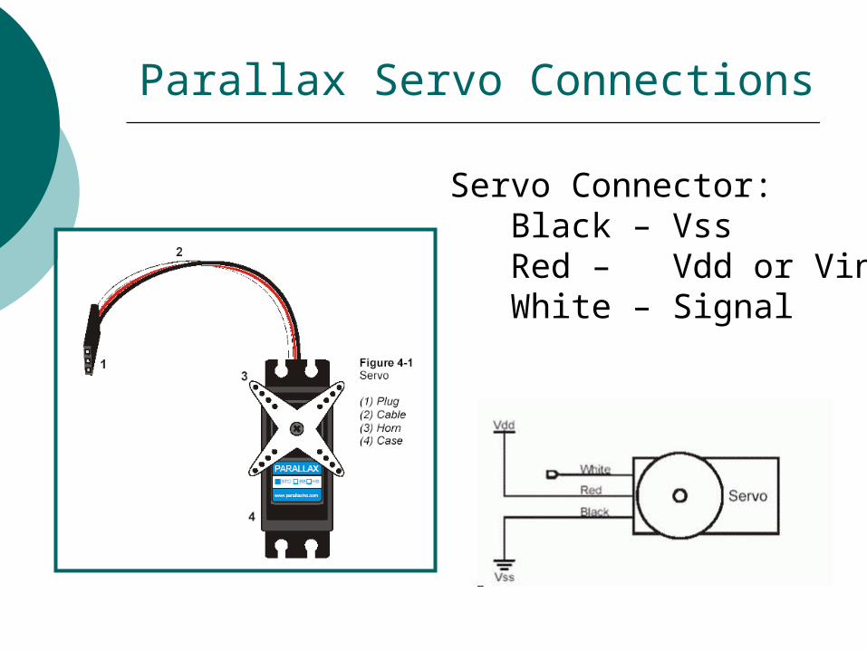
Parallax Servo Connections
Servo Connector: Black – Vss Red – Vdd or Vin White – Signal
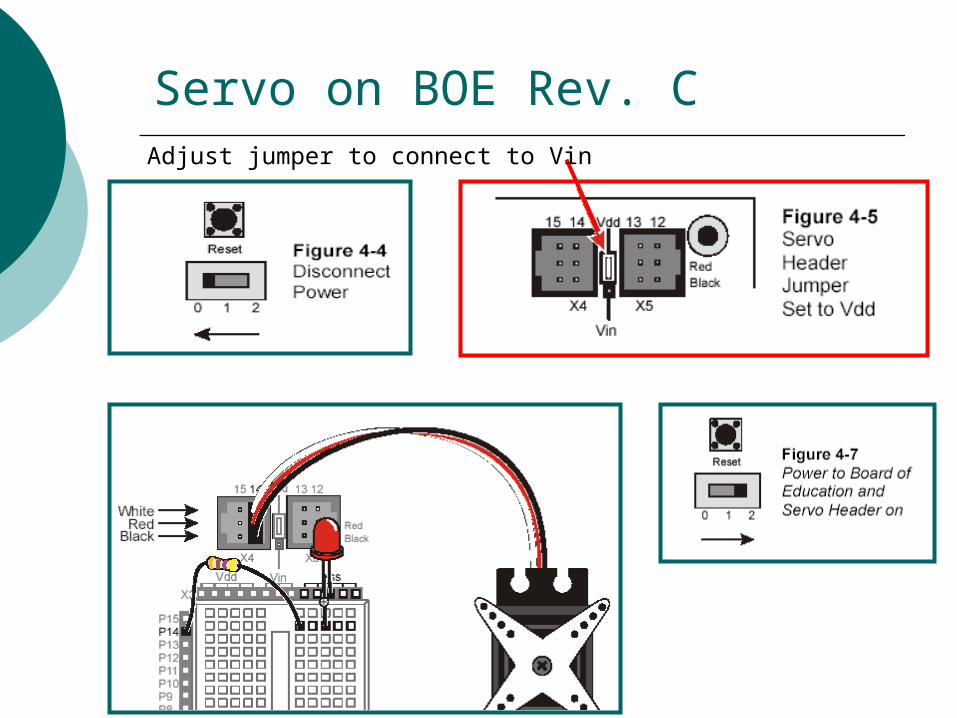
Servo on BOE Rev. CAdjust jumper to connect to Vin
Programming Servo Control
The servos is controlled by bursts of signals spaced 20mS apart. A high signal can last between 1mS to 2mS.
The PULSOUT instruction is used to send the signals:PULSOUT pin, durationpin: Defines which I/O pin to use.duration: defines how long the pulse should last, but it in NOT in mS.
PBASIC PULOUT command
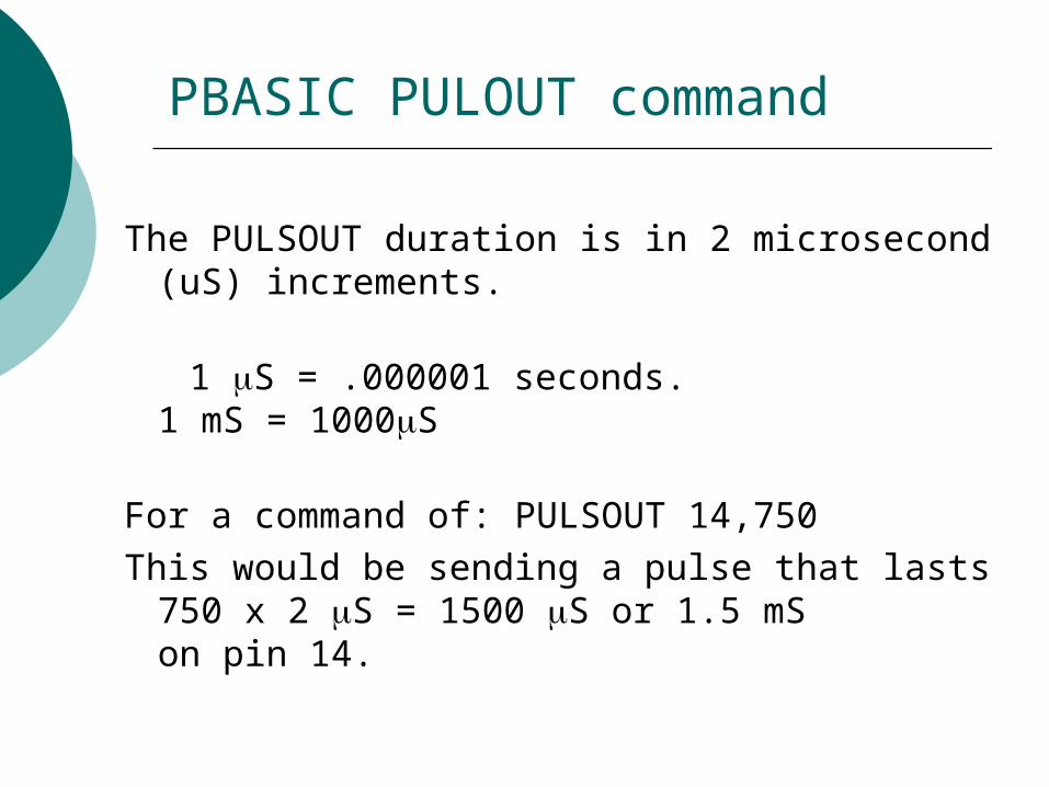
The PULSOUT duration is in 2 microsecond (uS) increments.
1 S = .000001 seconds.1 mS = 1000S
For a command of: PULSOUT 14,750This would be sending a pulse that lasts