Integrated Solver Optimized for the next generation 64-bit platform Finite Element Solutions for Geotechnical Engineering Session 2. Deep Excavations and Dewatering in Urban Environment MIDAS Geotechnical Know-how Sharing Series JaeSeok Yang Principal Geotechnical Engineer, MIDAS IT
Transcript
Integrated Solver Optimized for the next generation 64-bit platform
Finite Element Solutions for Geotechnical Engineering
Session 2.
Deep Excavations and Dewatering in Urban Environment
MIDAS Geotechnical Know-how Sharing Series
JaeSeok Yang Principal Geotechnical Engineer, MIDAS IT
Integrated Solver Optimized for the next generation 64-bit platform
Finite Element Solutions for Geotechnical Engineering
01 Modelling of Excavations
02 Prediction of Ground Movements
03 3D Excavation Modelling
04 Case Study
GTS NX
3
Surcharge Loading
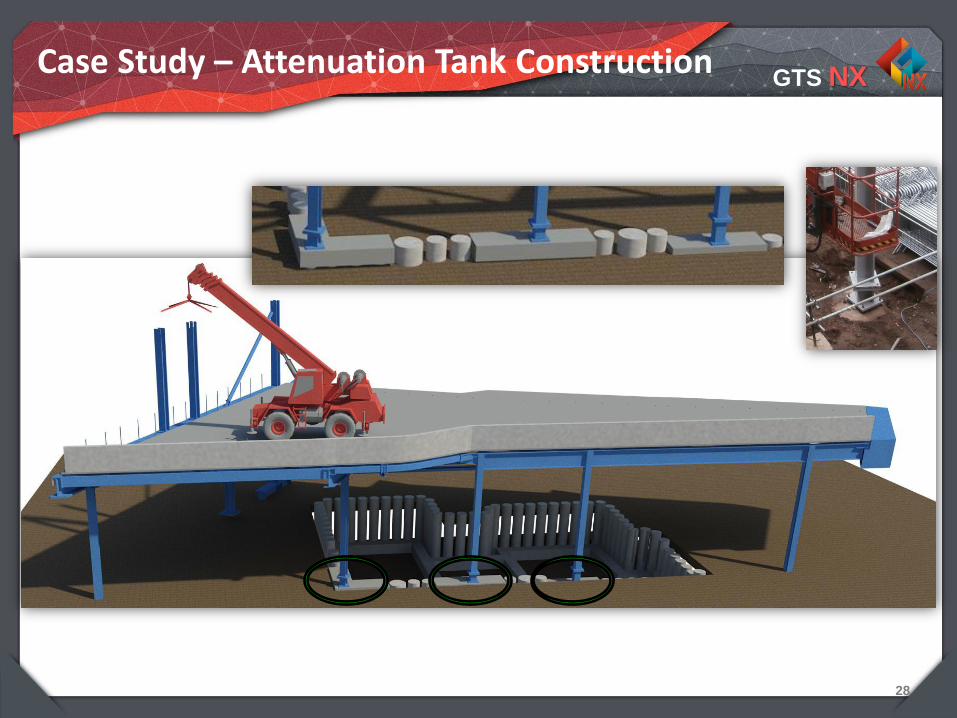
Modelling of deep excavation
ODEON excavation
villas
high school
Ténao street
Point du jour
GTS NX
4
Interface Behaviour
• Soil‐structure interaction
Wall friction
Slip and gapping between soil and structure
• Soil material properties
Taken from soil using reduction factor R
Individual material set for interface possible
GTS NX
5
Interface Behaviour
• Suggestions for R
• With reference to BS 8002
GTS NX
6
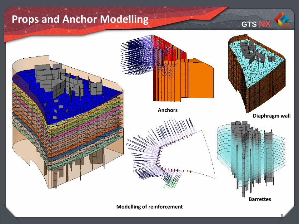
Props and Anchor Modelling
Diaphragm wall
Barrettes
Anchors
Modelling of reinforcement
Integrated Solver Optimized for the next generation 64-bit platform
Finite Element Solutions for Geotechnical Engineering
01 Modelling of Excavations
02 Prediction of Ground Movements
03 3D Excavation Modelling
04 Case Study
GTS NX
8
Material Behaviour in Excavation
• Unloading due to excavation
Vertical unloading at excavation bottom
Horizontal unloading behind wall (may accompanied by shear plasticity)
• Primary loading due to pre‐stressing
• HS-small model is preferred
Non‐linear elastic unloading/reloading behaviour
Shear plasticity due to horizontal unloading
High far‐field stiffness for better settlement trough prediction
GTS NX
9
Soil Non-linearity
Characteristic stiffness-strain behavior of soil with the ranges for typical geotechnical structures and different tests
GTS NX
10
Actual Resulting Strains
Strain contours around an excavation (after Simpson et al., 1979)
GTS NX
11
Determination of Ground Stiffness
Idealized stress paths associated with stress relief due to excavation (after Ng, 1999) (a) Effective stress paths; (b) total stress paths
GTS NX
12
Constitutive Models
• Mohr-Coulomb: unrealistic deformations
Use of single E fails to cater for the complex material at various zones
Overestimation over bottom heave
Sometimes heave of soil behind the wall
Soils below excavation behaves with Eur, even soils behind wall behaves between Eur