1 CSCI 4620/8626 Computer Graphics Introduction Last update: 2015-01-14 2 What is Computer Graphics? Computer graphics: graphics implemented through the use of computers, as well as the branch of science and technology concerned with methods and techniques for converting data to or from visual representation using computers. It is the second part of this definition with which we are concerned in this class.
Transcript
1
CSCI 4620/8626
Computer Graphics
Introduction
Last update: 2015-01-14
2
What is Computer Graphics?
Computer graphics: graphics implementedthrough the use of computers, as well as thebranch of science and technology concernedwith methods and techniques for convertingdata to or from visual representation usingcomputers.
It is the second part of this definition withwhich we are concerned in this class.
The definition of computer graphics suggests a[computer] graphics system may have three majorcomponents:
an input component
an output component
a processing component
Not all [computer] graphics systems possess eachcomponent. In particular, some systems may havelimited or no facility for graphic input.
3
5
Output Components
There are numerous types of output components forgraphics systems. Some of these include the following:
video display devices
printers
physical displays (i.e. surface models)
Technically, any device that provides visual output from acomputer system could be classified as a graphical outputcomponent (i.e. a light-emitting diode, or LED), but we’reprimarily concerned with devices capable of displaying atleast two-dimensional images.
6
Video Displays
Most video monitors previously used a cathode-raytube (CRT) to generate an image.
Now most modern devices use solid-statetechnology, and these are popular in hand-helddevices like cell phones, personal digital assistants(PDAs), laptop computers, and tablets.
Touch-sensitive displays are now becoming verycommon, but we can treat them as two separatedevices – a display device and an input device.
4
7
Cathode-Ray Tubes (CRTs)
The previously predominant technology for graphicdisplays was the CRT.
The basic components of a CRT are:
an electron gun that emits a narrow beam of electrons,
a focusing system that can redirect the beam ofelectrons, and
a phosphor-coated screen.
8
Vacuum Tubes
Prior to the invention of the transistor, virtually allelectronic devices (including radios, televisions, andcomputers) used vacuum tubes to process electronicsignals.
These vacuum tubes usually contained four components:the heater or filament (frequently operating from a 6.3 volt DCsupply),
the cathode (a cylinder, coated with an oxide, and wrapped aroundthe heater),
one (or more) grids, much like window screen, arranged inconcentric cylinders around the cathode, and
the plate or anode, a solid metal cylinder placed concentricallyaround the outermost grid.
5
9
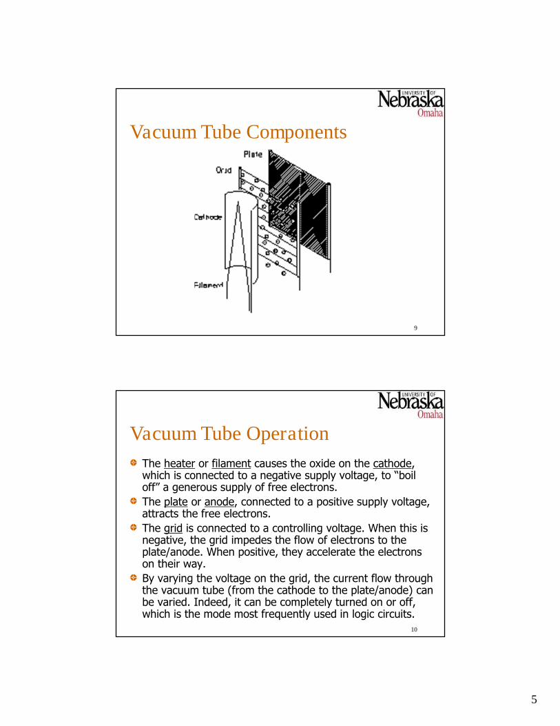
Vacuum Tube Components
10
Vacuum Tube Operation
The heater or filament causes the oxide on the cathode,which is connected to a negative supply voltage, to “boiloff” a generous supply of free electrons.
The plate or anode, connected to a positive supply voltage,attracts the free electrons.
The grid is connected to a controlling voltage. When this isnegative, the grid impedes the flow of electrons to theplate/anode. When positive, they accelerate the electronson their way.
By varying the voltage on the grid, the current flow throughthe vacuum tube (from the cathode to the plate/anode) canbe varied. Indeed, it can be completely turned on or off,which is the mode most frequently used in logic circuits.
6
11
CRT Operation
The electron gun in a CRT is a heater and cathodearranged so the electron beam (or beams, in color tubes) isdirected predominantly in a single direction.
A grid is used to control the flow, or intensity of theelectron beam.
Several intermediate anodes are used to accelerate andfurther focus the electron beam.
The focusing system (either electrostatic orelectromagnetic) is used to bend the electron beam so it isdirected toward a specific location on the screen.
The screen, coated on the inside with a phosphorescentmaterial, is essentially the anode, which is usually suppliedfrom a large positive voltage.
Basic Magnetic Deflection CRT(Cross-Section)
12
7
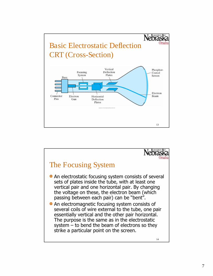
Basic Electrostatic DeflectionCRT (Cross-Section)
13
14
The Focusing System
An electrostatic focusing system consists of severalsets of plates inside the tube, with at least onevertical pair and one horizontal pair. By changingthe voltage on these, the electron beam (whichpassing between each pair) can be “bent”.
An electromagnetic focusing system consists ofseveral coils of wire external to the tube, one pairessentially vertical and the other pair horizontal.The purpose is the same as in the electrostaticsystem – to bend the beam of electrons so theystrike a particular point on the screen.
8
15
Electron Beam/Phosphor Interaction
When the electron beam strikes the phosphor-coated screen, it stops (mostly), with its kineticenergy converted to heat and and increasedquantum-energy for the electrons in the phosphor.
After a short time, the phosphor electrons dropback to their original energy levels, releasing theirextra energy as photons (light).
What we see (on the other side of the screen!) isthis light emitted by the phosphor electrons.
16
The Phosphor
Different kinds of phosphors can be used in CRTs.
The major classifications of phosphors include:
Color: what frequency of light is emitted when theexcited phosphor electrons revert to their non-excited,or ground states?
Persistence: how long does it take all the excitedphosphor electrons to return to the ground state?
Resolution (which depends on other factors as well):how small a phosphorescent region on the screen can beexcited without affecting neighboring regions?
9
17
Displaying Images
To display an image on a CRT, a computer system mustarrange to excite regions on the screen that correspond tothe image.
Since the phosphor has a limited persistence (typically from10 to 60 microseconds), an image must be continually“refreshed” or redrawn on the screen.
There also exist (or existed) earlier displays using “storagetube” technology which included features that automaticallymaintained an image; a new image could only be drawnafter entirely erasing the existing image, which wasbasically an atomic operation (that is, parts of the imagecould not be erased individually).
18
Refreshing Images
There are two basic techniques used to refresh the imageon the screen of a CRT:
raster-scan displays, and
random-scan, (line-drawing or vector) displays
Raster-scan displays continuously move the electron beamin horizontal scan lines across the screen, working from thetop down. As the beam moves across the screen, the beamintensity is adjusted to create a pattern of illuminatedspots.
Random-scan displays simply move the beam across thescreen to construct a sequence of connected ordisconnected lines, which need not be horizontal.
10
A Random Scan Display
19
20
Raster-Scan Displays
The data a raster-scan display uses to determine how tocontrol the electron beam is stored in a data structurecalled the refresh buffer, or more commonly the framebuffer. This is because a single image as displayed on thescreen is frequently called a frame.
The smallest spot on a screen that can logically becontrolled is called a pixel, or pel (for picture element).
When a color CRT (capable of displaying multiple colorssimultaneously) is in use, the refresh buffer is sometimescalled a color buffer.
11
Operation of Raster Scan Display
21
22
Interlaced Video
In typical television systems (and some computerdisplay systems), two passes over the screen arerequired to display a complete image.
In the first pass, all the odd-numbered scan linesare refreshed.
Then the second pass refreshes all the even-numbered scan lines.
This technique is used to “fool” the eye intobelieving that frames are actually being displayedmore rapidly.
12
Scan Line Interlacing
23
24
Other Attributes
CRT (and other) display devices are alsocharacterized by an aspect ratio, which isessentially the width of the display divided by itsheight. These measures could be in inches orcentimeters, or in pixels and scan lines.
Another attribute is intensity. This is a measure ofthe strength of the electron beam. The simplestsystems may only allow the beam to be totally“on” or “off”, while other systems may give moreprecise control of the beam intensity.
13
25
Color Attributes
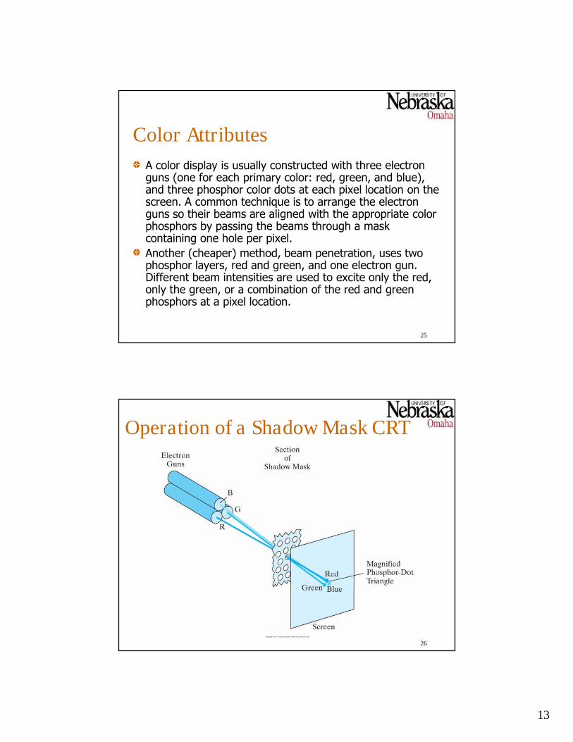
A color display is usually constructed with three electronguns (one for each primary color: red, green, and blue),and three phosphor color dots at each pixel location on thescreen. A common technique is to arrange the electronguns so their beams are aligned with the appropriate colorphosphors by passing the beams through a maskcontaining one hole per pixel.
Another (cheaper) method, beam penetration, uses twophosphor layers, red and green, and one electron gun.Different beam intensities are used to excite only the red,only the green, or a combination of the red and greenphosphors at a pixel location.
Operation of a Shadow Mask CRT
26
14
27
Color and Intensity Implications
When a monochrome display with only “on/off”pixel control is used, the frame buffer needs onlyone bit for each pixel. For example, a bitcontaining 1 might mean to turn “on” a particularpixel.
When a display is to provide color and/or morethan two intensities, then each pixel in the framebuffer must have a suitable number of bits. Forexample, with only “on/off” control of three colors,each pixel in the frame buffer will need three bits.
Graph of Intensity Near a Pixel
28
15
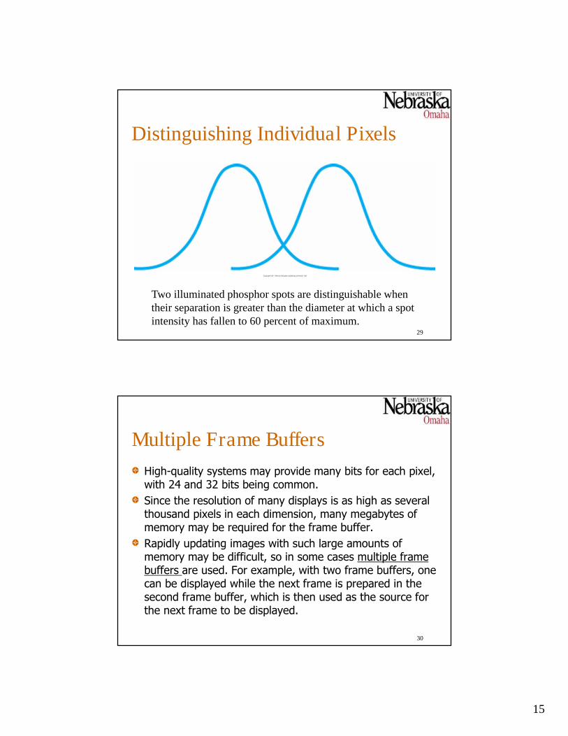
Distinguishing Individual Pixels
29
Two illuminated phosphor spots are distinguishable whentheir separation is greater than the diameter at which a spotintensity has fallen to 60 percent of maximum.
30
Multiple Frame Buffers
High-quality systems may provide many bits for each pixel,with 24 and 32 bits being common.
Since the resolution of many displays is as high as severalthousand pixels in each dimension, many megabytes ofmemory may be required for the frame buffer.
Rapidly updating images with such large amounts ofmemory may be difficult, so in some cases multiple framebuffers are used. For example, with two frame buffers, onecan be displayed while the next frame is prepared in thesecond frame buffer, which is then used as the source forthe next frame to be displayed.
16
31
Refresh Rates
How rapidly should the electron beam be movedover the scan lines?
The human eye “blurs” discrete events if theyoccur with sufficient frequency. Early motionpictures used 24 frames per second, but thiswasn’t sufficient to avoid yielding what appearedto be jerky motion by the actors.
Modern display systems typically use a refresh rateof 60 to 80 frames per second, with high endsystems providing as high as 120 frames persecond.
32
Horizontal and Vertical Retrace
When the electron beam reaches the end of ahorizontal scan line, it is turned off and moved tothe beginning of the next scan line (if there isone); this is called horizontal retrace.
After the end of the last (lowest) scan line isreached, the beam is again turned off and movedto the beginning of the first scan line; this is thevertical retrace.
17
33
Dual-Ported Memory
The frame buffer in a system is accessed from the systembus to update the image being displayed, and from thevideo circuits that generate the raster scan.
In early systems, if the frame buffer was being accessedfrom the bus, then the video circuits were denied access.Making changes to the image at arbitrary times led toimages with spots, or “snow,” since the video circuitscouldn’t maintain the proper timing.
Later, systems were designed to report (by an interrupt)when the vertical retrace period started, so frame bufferupdates could be performed without image problems.
Modern frame buffers are built using dual-ported memory,which allows simultaneous access from several “ports.”
34
Flat Panel Display Technology
Several technologies permit displays to beconstructed without using CRTs which, by theirnature, make it difficult to build large low-power,lightweight displays.
The two basic categories of flat panel technologiesare:
emissive – covert electrical energy to light
non-emissive – convert existing light to images
18
35
Plasma (Gas Discharge) DisplaysThese devices use two parallel glass plates, with the regionbetween them filled with a mixture of gases (usuallyincluding neon).
One plate has a series of horizontal conducting ribbons,and the other has a series of vertical ribbons.
By applying a suitable voltage to one horizontal and onevertical ribbon, the gas in the region near the intersectionof the conductors will break down into a glowing plasma ofelectrons and ions.
Each pixel position is typically refreshed 60 times eachsecond.
AC (as opposed to DC) is used to provide faster applicationof voltages and brighter displays.
Early systems were only monochrome, but color systemsare now available.
Basics of a Plasma Panel Display
36
19
37
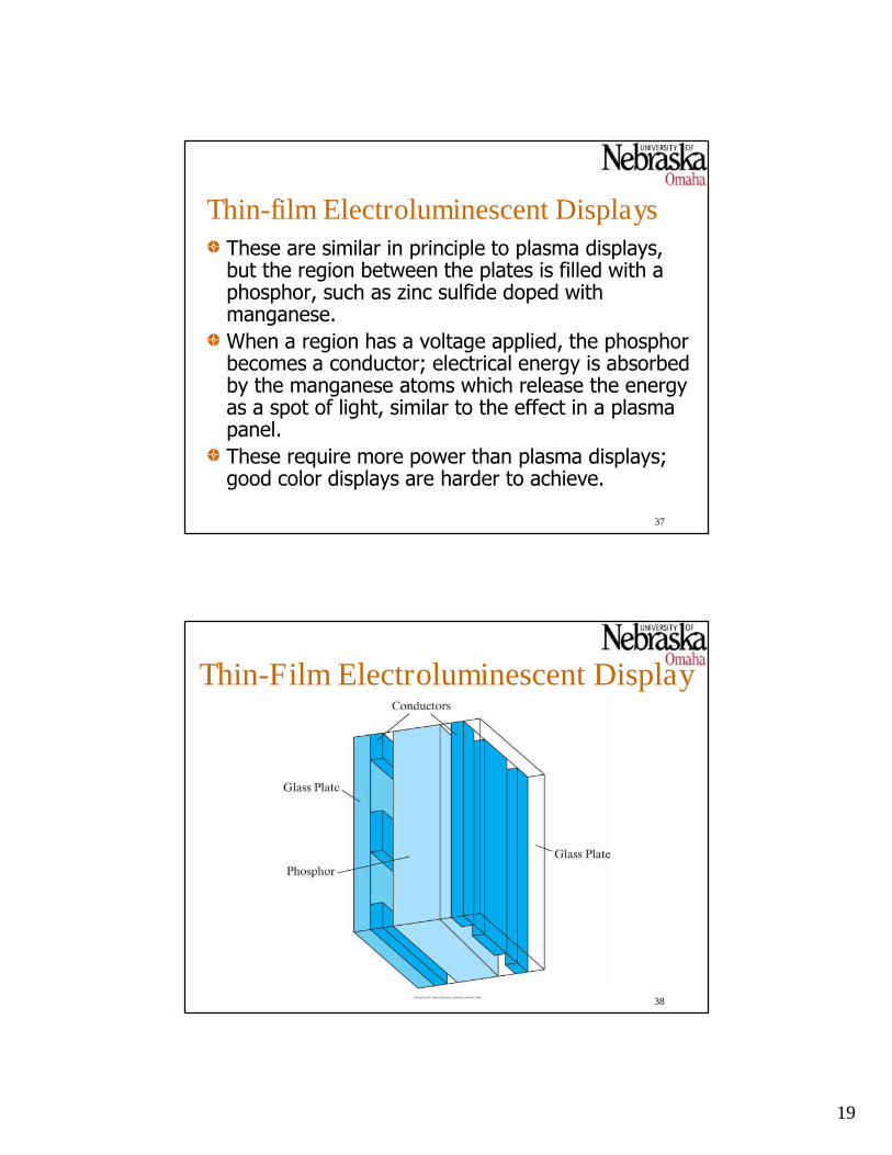
Thin-film Electroluminescent DisplaysThese are similar in principle to plasma displays,but the region between the plates is filled with aphosphor, such as zinc sulfide doped withmanganese.
When a region has a voltage applied, the phosphorbecomes a conductor; electrical energy is absorbedby the manganese atoms which release the energyas a spot of light, similar to the effect in a plasmapanel.
These require more power than plasma displays;good color displays are harder to achieve.
Thin-Film Electroluminescent Display
38
20
39
Liquid Crystal Displays (LCDs)These very common non-emissive systems function bypassing, or not passing, polarized light through liquid-crystal material that can be aligned appropriately.
Liquid-crystal compounds have a crystalline arrangement ofmolecules, but flow like liquids. A nematic (or threadlike)liquid-crystal compound is used in these displays.
Display construction is similar to plasma devices, in thattwo plates with conductors are used. The plates also havepolarizing materials applied at 90-degree angles to eachother.
In the “on” state, the crystals twist at 90-degree angles,thus correctly aligning incident light so it will pass throughthe two plates. In the “off” state, light isn’t bent and doesnot pass through the display.
Design of Most LCD Devices
40
21
41
LCD Variations
The basic device described in the previous slide is called apassive-matrix device, since no image is actually stored init. A frame buffer must be used to provide for continual (60times per second) refresh of the display.
Colors can also be displayed by using different materialsand dyes, and placing three pixels at each screen location.
Backlighting is sometimes used to provide an independentlight source for the display, making them easier to read inlow-light environments.
Active-matrix devices employ a transistor at pixel locations,allowing the pixel state and the charge on the liquid-crystalto be maintained more easily.
42
Three-Dimensional Displays
By “three-dimensional” displays, we mean displays thatgive the appearance of depth, in addition to height andwidth.
One scheme for producing such an image is to dynamicallychange the focal length to an image by reflecting it througha vibrating mirror which is synchronized with the image ona CRT.
Another technique provides separate stereoscopic imagesto each eye. Special goggles, or glasses, with two smalldisplays are typically used to present these images to aviewer.
22
A 3D Display System
43
44
Virtual Reality
In virtual reality systems, a user is allowed to “stepinto” an environment and interact with it.
This is done using a stereoscopic three-dimensional display and one or more feedbackmechanisms. Examples include:
sensors that can detect the movement of the viewer’shead so that appropriate images can be displayed
a data glove can detect the movement of the viewer’shand, so virtual objects can be manipulated
23
45
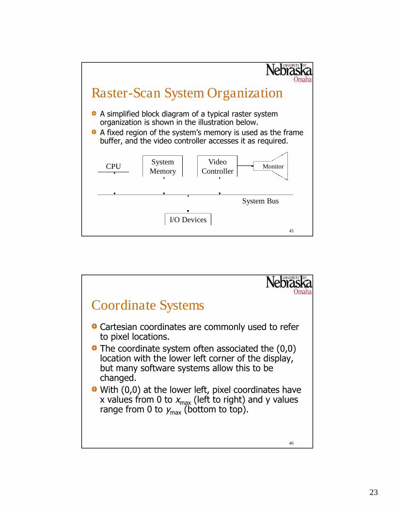
Raster-Scan System Organization
A simplified block diagram of a typical raster systemorganization is shown in the illustration below.
A fixed region of the system’s memory is used as the framebuffer, and the video controller accesses it as required.
CPUSystemMemory
VideoController
Monitor
System Bus
I/O Devices
46
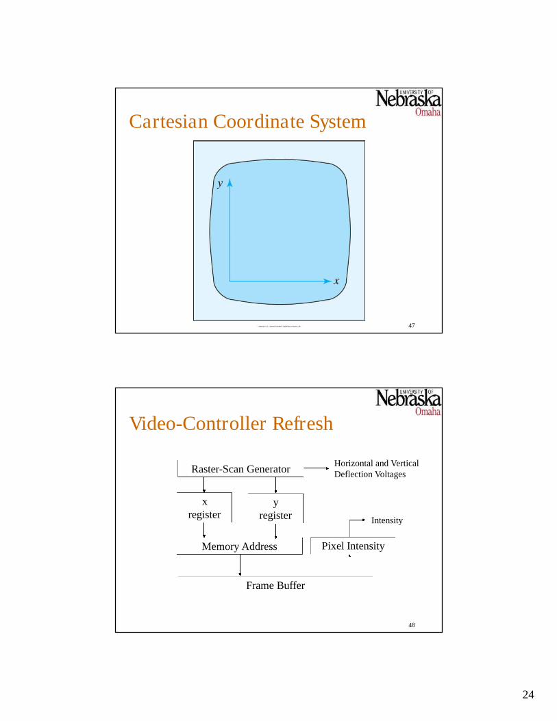
Coordinate Systems
Cartesian coordinates are commonly used to referto pixel locations.
The coordinate system often associated the (0,0)location with the lower left corner of the display,but many software systems allow this to bechanged.
With (0,0) at the lower left, pixel coordinates havex values from 0 to xmax (left to right) and y valuesrange from 0 to ymax (bottom to top).
24
Cartesian Coordinate System
47
48
Video-Controller Refresh
Raster-Scan Generator
xregister
yregister
Memory Address
Frame Buffer
Pixel Intensity
Horizontal and VerticalDeflection Voltages
Intensity
25
49
Display Processors
Although it is still common to call the videohardware in a computer the “video controller,”most systems actually employ a separate displayprocessor (sometimes called a graphics controlleror display coprocessor).
This device includes its own dedicated frame bufferand video controller, as well as one or moreseparate processors, called GPUs – graphicprocessing units – to automate many of the time-consuming graphics tasks previously performed bythe system’s CPU.
System with a Display Processor
50
26
51
Display Processor Functions
As an example, drawing a straight line segment on adisplay requires computing the Cartesian coordinates ofeach pixel that is to be part of the line’s image, and thensetting the corresponding locations in the frame buffer tothe appropriate values (the so-called “scan conversion”process). Most display processors can accept a singlecommand to draw a straight line and perform all of therequired tasks by themselves, freeing the system CPU forother tasks.
Display processors can also be designed to interact withadditional interactive input devices, like a mouse.
52
Text-only Displays
Each character of text is (usually) a rectangular region ofpixels, some of which are on.
Early text-only displays had frame buffers with 24-rows and80-columns of bytes, each containing a character code.
The raster-scan process scans a single row of charactercodes N times (where N is the pixel height of a character),using each character code as the index to an arraycontaining the corresponding pixel row, which is thenoutput to the display. The process repeats for each of thecharacter rows, and the begins again.
27
Character Shape in Pixels
53
54
Modern Text Display Systems
Modern systems that display both text andgraphics still handle text by expecting a string ofcharacter codes to be provided.
These codes are still used as index values intoarrays defining the pixel boxes for characters (ineach of numerous different fonts), but the displayprocessor will handle the superimposition of thepixel boxes on the frame buffer (which mayalready contain other graphics). The displayprocessor may also do the needed font sizescaling.
28
Character Outline
55
56
Graphic Encoding Techniques
Early systems attempted to minimize the memoryrequirements by encoding graphic images.
One such scheme, called Run-Length Encoding (RLE),recorded two values, color and number of pixels, for eachcontiguous region of a scan line having the same color. Iflarge regions of a scan line are the same color (as iscommon), then significant memory savings may occur.
Memory is now sufficiently inexpensive so that suchtechniques are not commonly used in controllers.
However there are numerous encoding techniques used toencode graphics for longer-term storage and transmission.Common standards-based techniques include JPEG, PNG,and GIF.
29
57
Input Devices
A variety of devices for data input have been developed foruse in graphics systems, including:
Keyboards, button boxes, and dials
Mice
Trackballs
Joysticks
Data gloves
Digitizers
Image scanners
Touch panels
Light pens
Voice recognition systems
58
Mice, Trackballs, and Joysticks
The basic “mouse” contains a mechanism that provides areport of how many “mickeys” (the mouse equivalent of apixel) it is moved in the x and y directions, and one or morebuttons that can be clicked.
A trackball is similar to a mouse, but instead of measuringmovement on a flat surface, the trackball is a sphere that isrotated by the user; the amount of movement is report thesystem.
Mice and trackballs may typically internally rotate a diskmarked with light and dark regions, with photosensorsdetecting how many regions have been passed, or theymay rotate potentiometers (e.g. variable resistors).
A joystick reports the absolute position of a small verticallever using two potentiometers, one for each direction.
30
59
Data Gloves
These devices are gloves (frequently only a singleglove) with sensors located at critical points (e.g.finger joints) and perhaps sensors that identify theposition of the hand in space (using, for example,infrared or RF techniques).
Input based on the movement of the user’s handcan be used to effect changes in a virtualenvironment, with a representation of theenvironment then supplied as an image to theuser, perhaps in three dimensions.
60
Digitizers
Digitizers essentially translate the position of a pen, afinger, or some other “pointing device” into a coordinate, orsequence of coordinates that are used by the computersystem.
Several techniques can be used to detect the stylusposition. A common technique uses a pressure-sensitivetablet to which the stylus or finger is applied. This is mostuseful for free-hand drawing.
Another technique is essentially a “crosshair” that can bepositioned over a drawing, and buttons that can be pressedto transmit a position. This is useful for digitizing existingdrawings.
31
61
Image Scanners
Document or image scanners are common devices.
Most scanners pass a linear array of opticalsensors over an illuminated image from top tobottom (or pass the image over a fixed array ofsensors), transmitting the sensor readings to thecomputer system which constructs a digitalrepresentation.
Both monochrome and color scanners arecommon.
62
Touch Panels
A touch panel is essentially a display with an array ofsensors that can detect when a finger or other stylus ispressed to the display.
Optical panels might use infrared sensor grids in front ofthe display, so that a finger will occlude the infrared signalat a point whose Cartesian coordinates can be obtained andrelated to the image being displayed.
Other techniques include electrical (which senses pressureon the display screen) and acoustic (which scatters a high-frequency signal differently depending on where the fingeris placed).
32
63
Light Pens
Similar in effect to touch panels, light pens containa sensor that is sensitive to the light generated bythe phosphor in a CRT.
When the pen is pressed to a location on the CRTand light strikes it, a signal is sent from the lightpen to the controller. The position of the electronbeam at that instant can then be used todetermine where the pen was pressed.
Light pens are not as popular today as they oncewere; they were primarily used with terminalsconnected to mainframe computer systems.
64
Voice Recognition Systems
Voice recognition systems recognize words or certain otherutterances by matching frequency patterns in audio inputwith those in a “dictionary.”
For very limited vocabularies (for example, the decimaldigits and “yes/no”), some systems may succeed withouttraining. In general, however, each user must speak everyword they expect to be recognized, perhaps repeatedly, toestablish the expected frequency patterns.
Voice recognition systems free the user’s hands foroperation of other devices, and are commonly used to entera limited set of commands that would normally come fromthe keyboard or mouse clicks.
33
65
Hard-Copy Devices
Static images can be produced on a variety ofmedia, including
overhead transparencies
slides and film
paper
Quality is influenced, as expected, by pixel density.
Media like slides and film are produced byexposing a frame of film to the image displayed ona display.
66
Printers
Impact printing presses a metal die against the paperthrough a ribbon; the die can be an individual dot/pixel, orcan represent a character (for example, in text-onlydevices).
Ink-jet printers use an electric field to direct smallelectrically charged ink streams onto the paper.
Electrostatic (laser) printing places a negative charge on acharged drum in positions that are to receive toner. Thedrum selectively collects charged toner and transfers theimage to the paper. The toner is then fused to the paper.
Thermal printing (now less popular) applies heat from theprinting device to heat-sensitive paper to form images.
34
67
PlottersIn most printers, the printing mechanism moves in only onedirection (usually horizontally) across the page, with thepaper moving vertically. Much of the mechanical activity ina plotter is associated with paper movement.
Small plotters (largely made obsolete by ink jet and laserprinters) usually apply an image to a fixed page by movingthe printing mechanism (usually a set of pens that can beraised or lowered) in both the horizontal and verticaldirections.
Large-format plotters (about the only ones commonly usedtoday) use a movable drum across which the paper isdraped and a printing mechanism that moves only in onedirection (usually horizontally) across the drum and paper.