SET3041 Energy from Biomass 2009/2010 Major Assignment Group 10 Methanol from woody biomass Direct gasification of woody biomass via entrained flow reactor Group 10 Rajeev Baran 1222996 [email protected]elft.nl Shekil Mahesh 1270028 [email protected].nl Isabelle Declerck 1278908 [email protected].nl Andreas Höllbacher 1229311 [email protected]elft.nl Supervisors Dr.ir. W. de Jong X. Meng
For the Energy from Biomass course of the Sustainable Energy Technology Master at TU
Delft the production of methanol from woody biomass had to be examined. For this exercise
an entrained flow, downdraft gasifier is considered to gasify torrefied pine wood. The
gasification process is modelled using simple molar and thermodynamic equilibrium methods
which are implemented in Matlab. From the resulting product gas composition the amount of syngas required to meet the demand of 250 kton of methanol production per annum. The
amount of torrefied pinewood required amounts to 1460 kton per year.
Equation 5 is a combination of the first two reactions (eq. 3, the Boudouard reaction and eq. 4,
the water-gas shift reaction) and is called the CO shift reaction. Equation 6 represents the
formation of methane or the methanation reaction. Together with the fifth equation they are
the major reactions occurring in the gasification process.
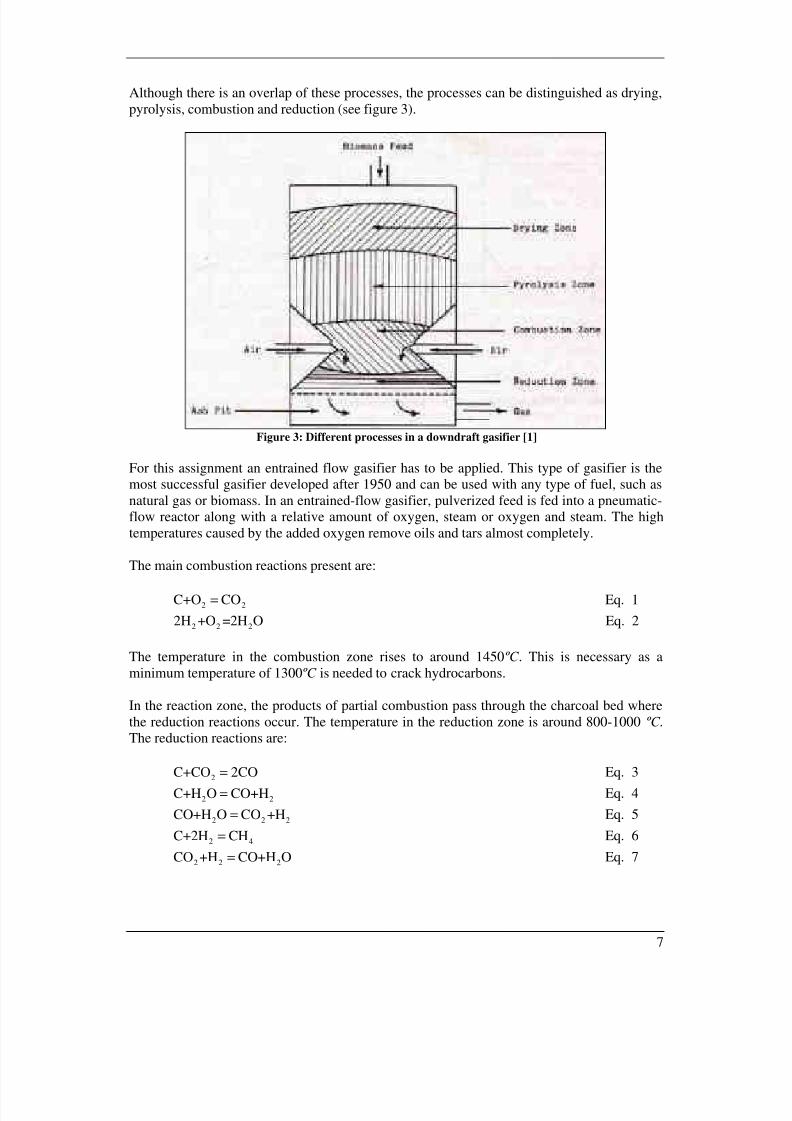
In the pyrolysis zone H2O, CO2 and other volatile products like tar are given off at
temperatures between 200 and 500 ºC. The downdraft gasifier leaves less tar behind, becausethe material has to move through the combustion zone and is partially broken down.
In the drying zone, as the name already implies, the wood is dried. The wood entering the
gasifiers has a moisture content that is not favourable. During the woods transit through the
drying zone, the moisture content is lowered.
Pre-treatment
As most biomass types are not suitable for direct use in entrained flow gasifiers, pre-treatment
is necessary. The applied woody biomass is the most used type of renewable energy source
today, especially in developing countries. The advantage of using woody biomass as a
feedstock is that it does not conflict with conventional agriculture, such as the use of food
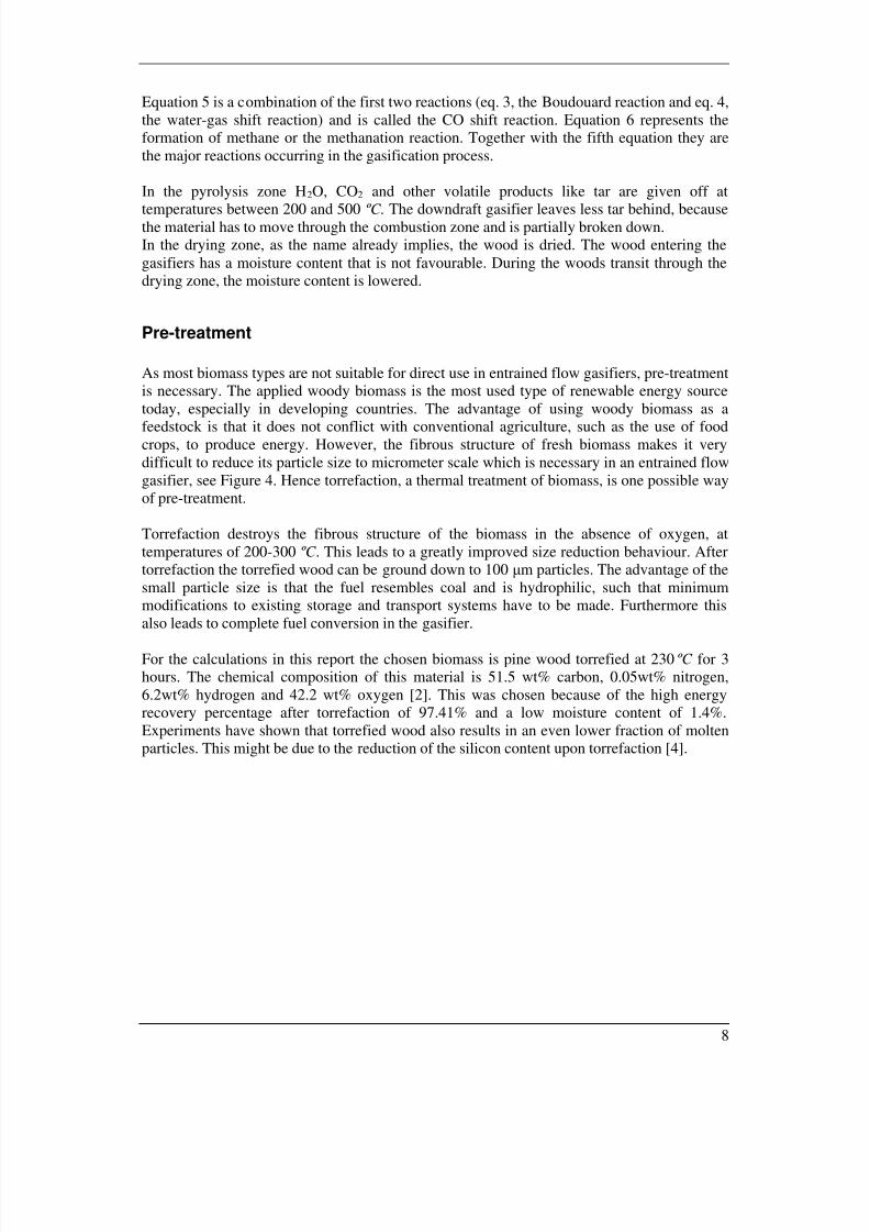
crops, to produce energy. However, the fibrous structure of fresh biomass makes it very
difficult to reduce its particle size to micrometer scale which is necessary in an entrained flow
gasifier, see Figure 4. Hence torrefaction, a thermal treatment of biomass, is one possible way
of pre-treatment.
Torrefaction destroys the fibrous structure of the biomass in the absence of oxygen, at
temperatures of 200-300 ºC . This leads to a greatly improved size reduction behaviour. After
torrefaction the torrefied wood can be ground down to 100 µm particles. The advantage of the
small particle size is that the fuel resembles coal and is hydrophilic, such that minimum
modifications to existing storage and transport systems have to be made. Furthermore this
also leads to complete fuel conversion in the gasifier.
For the calculations in this report the chosen biomass is pine wood torrefied at 230 ºC for 3
hours. The chemical composition of this material is 51.5 wt% carbon, 0.05wt% nitrogen,
6.2wt% hydrogen and 42.2 wt% oxygen [2]. This was chosen because of the high energy
recovery percentage after torrefaction of 97.41% and a low moisture content of 1.4%.
Experiments have shown that torrefied wood also results in an even lower fraction of molten
particles. This might be due to the reduction of the silicon content upon torrefaction [4].
Figure 4: Power consumption pulverisation wood vs. torrefied wood [4]
Proposed Reactor
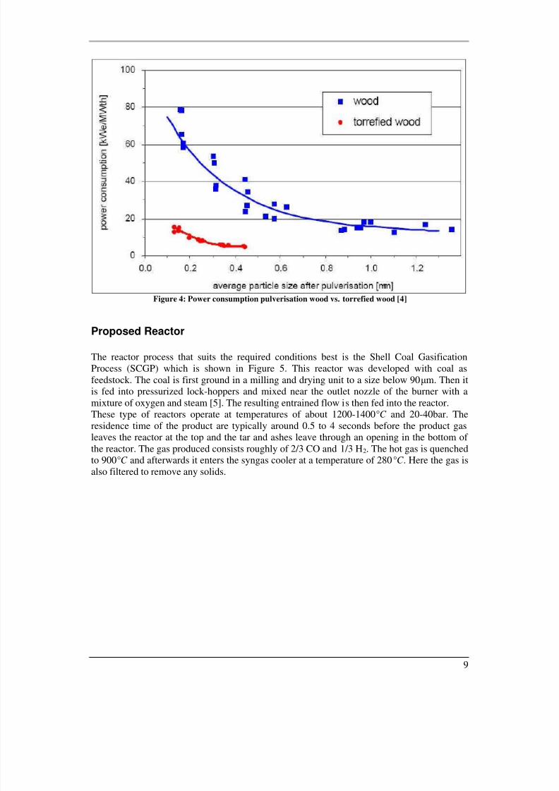
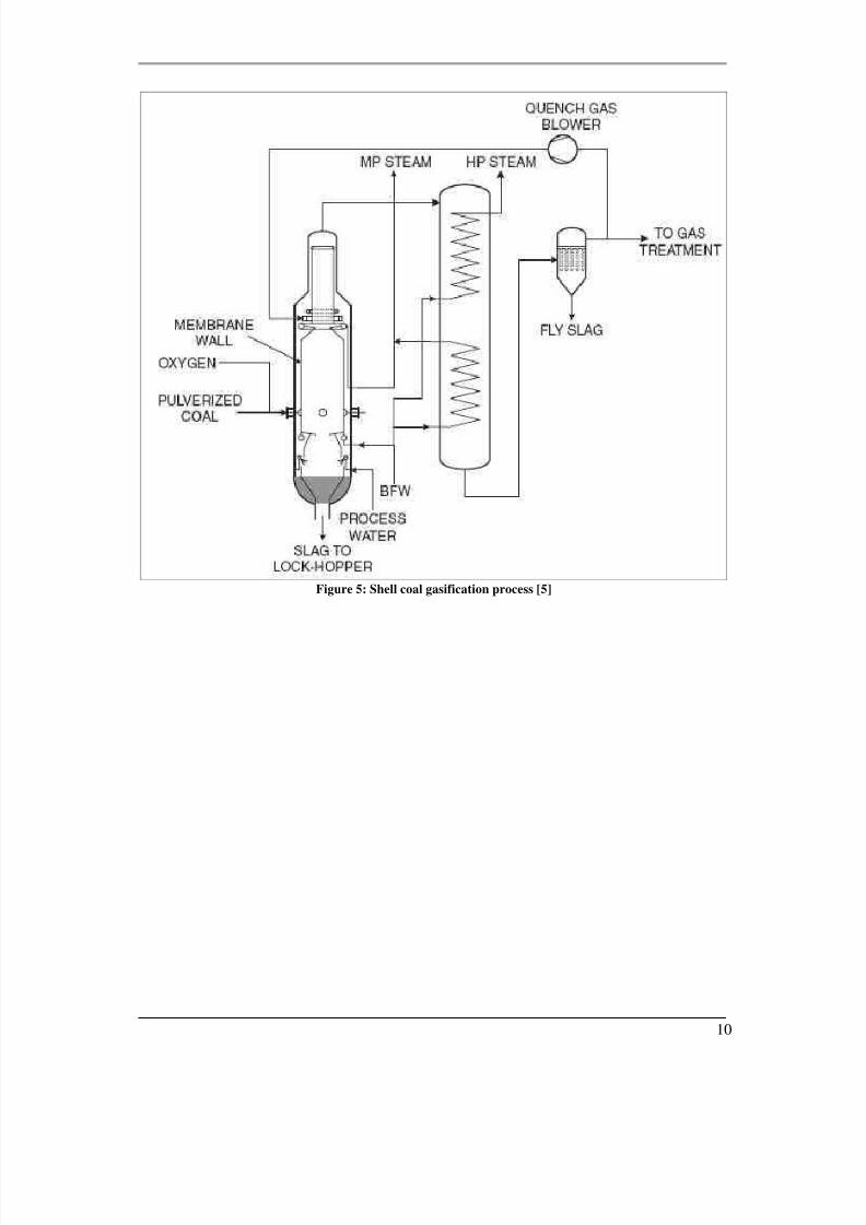
The reactor process that suits the required conditions best is the Shell Coal Gasification
Process (SCGP) which is shown in Figure 5. This reactor was developed with coal as
feedstock. The coal is first ground in a milling and drying unit to a size below 90µm. Then it
is fed into pressurized lock-hoppers and mixed near the outlet nozzle of the burner with a
mixture of oxygen and steam [5]. The resulting entrained flow is then fed into the reactor.These type of reactors operate at temperatures of about 1200-1400°C and 20-40bar. The
residence time of the product are typically around 0.5 to 4 seconds before the product gas
leaves the reactor at the top and the tar and ashes leave through an opening in the bottom of
the reactor. The gas produced consists roughly of 2/3 CO and 1/3 H2. The hot gas is quenched
to 900°C and afterwards it enters the syngas cooler at a temperature of 280°C . Here the gas is
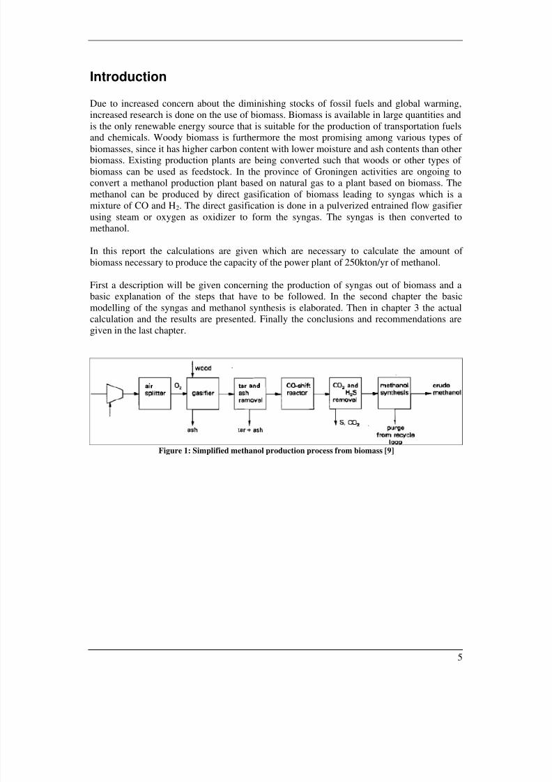
After gasification the syngas can be used as a feedstock for the production of methanol.
Methanol can be made out of almost all organic materials and can be used as a transportation
fuel in combustion engines. This leads to a CO2 neutral fuel. The process for the production of
methanol from syngas is the same as for the production from natural gas.
To produce methanol the syngas should be first cleaned of tar and dust and should be cooled.
The hot gas leaving the entrained flow gasifier might contain molten particles and fouling of
the heat exchanger surfaces may occur. Therefore, first quenching to 900°C is performed to
avoid ash related fouling. In a CO-shift reactor the ratio CO/H2 can be adjusted by steam
addition via the catalytically enhanced slightly exothermic reaction given below.
2 2 2CO+H O CO +H→ Eq. 8
Furthermore, the syngas should be cleaned of CO2 and H2S. H2S is a catalyst poison and has
to be removed completely. Wood only contains small amounts of sulphur and therefore thiscan be neglected at this moment.
The gas streaming out of the gasifier has a temperature of about 300-500 ºC this has to be
cooled to raise its energy density.
Methanol is produced with the use of a Cu/Zn/Al catalyst for hydrogenation of carbon oxides.
The reactions are exothermic and decrease the molar volume, for this reason the temperature
should be low with high pressure. During methanol production heat is produced that should
be removed to maintain optimum catalyst life and reaction rate [7]. The last step is distillation.
In this step the water that is produced during methanol synthesis is separated from the
methanol.
Conventional methanol reactors are fixed bed reactors using catalyst pellets operating in gasphase. The two most commonly used reactors are the ICI and the Lurgi. They both operate
between temperatures of 200-300°, pressures between 50-100bar and use a copper based
catalyst.
The main reaction for methanol synthesis is:
2 3CO+2H CH OH = Eq. 9
If there is an excess of hydrogen one can add CO2 to the reactor to increase yield using the
following reaction:
2 2 3 2CO +3H CH OH H O= + Eq. 10
The overall reaction becomes:
2 2 3 2CO+CO +5H 2CH OH H O= + Eq. 11
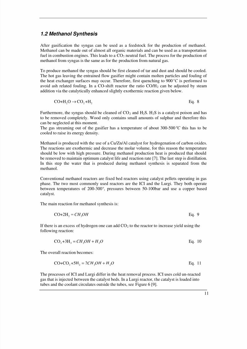
The processes of ICI and Lurgi differ in the heat removal process. ICI uses cold un-reacted
gas that is injected between the catalyst beds. In a Lurgi reactor, the catalyst is loaded into
tubes and the coolant circulates outside the tubes, see Figure 6 [9].
When considering a process such as the production of methanol from biomass it is essential to
be able to make estimates of the system performance. The simple equilibrium methods
described in the following sections have been reported to lead to reasonably accurate results
[6, 8].
2.1 Biomass Gasification
In order to estimate the output of the gasifier a thermodynamic equilibrium model will be
applied. In the previous section some operating conditions are already mentioned. These and
additional assumptions need to be taken into account before setting up the model:
• The used gasifier is a downdraft entrained-flow gasifier, as the equation holds better
for reactors with low tar content.
•
The operating temperature and pressure of biomass to syngas gasifier is 1200°C and20 bar respectively.
• The residence time of the feedstock in the rector is long enough such that it operates
close or at the thermodynamic equilibrium.
• All carbon content is converted into gaseous form.
• Only the main reaction products are taken into account. These are carbon monoxide(CO), carbon dioxide (CO2), hydrogen (H2), methane (CH4), nitrogen (N2), and water
(H2O).
• Ash in the feedstock is assumed to be inert.
• All gaseous products behave as ideal gases.
• The pressure drop inside the gasifier is assumed negligible.
• The process is adiabatic and no external heat source is applied.
• Only the main and overall reactions of the control volume (the gasifier) are used.
Individual processes going on in the different zone of the reactor are inside of the
control volume and do not need to be considered.
The last assumption characterises the reaction and is therefore used for the calculation (see
equation 11). During gasification an amount of reactants enter the reactor and a particular
amount of products exit the reactor. The reactants consist of the biomass, the moisture content
of the biomass and the air used for the gasification. The products are hydrogen, carbon
monoxide, carbon dioxide, water, methane and nitrogen.
The resulting overall gasification reaction is shown in equation 12 and is similar to the
equation set up by Gautam [6] and Babu [8].
2 2 2
1 2 2 3 2 4 2 5 4 2
( 3.76 )
3.76
x y w g
g
CH O m H O x O N
x CO x H x CO x H O x CH x N
+ + +
→ + + + + +Eq. 12
With x yCH O representing the equivalent composition for woody biomass (neglecting the
nitrogen content as it is very low for torrefied wood). The unknowns to be solved for are the
fractions xg, x1, x2, x3, x4 and x5. The moisture content m [wt%] of the wood is taken into
This chapter discusses the calculations and the results. In the first section the general chemical
equilibrium reactions are solved for the gasifier. In the subsequent section the calculations on
the methanol synthesis reaction are performed in order to determine the amount of syngas
needed. The third section deals with determining the amount of biomass feedstock needed,while the fourth section analysis reactor sizing. This chapter ends with an overview of the
results.
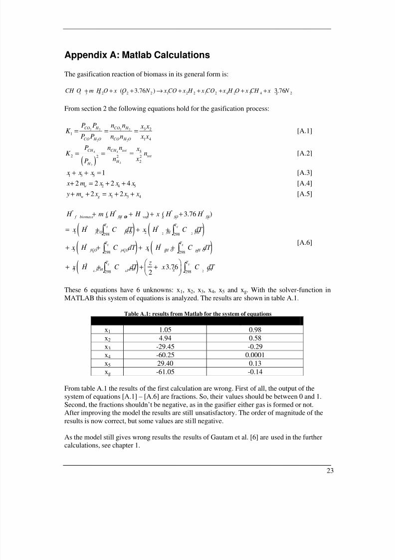
3.1 Determining the performance of the gasification
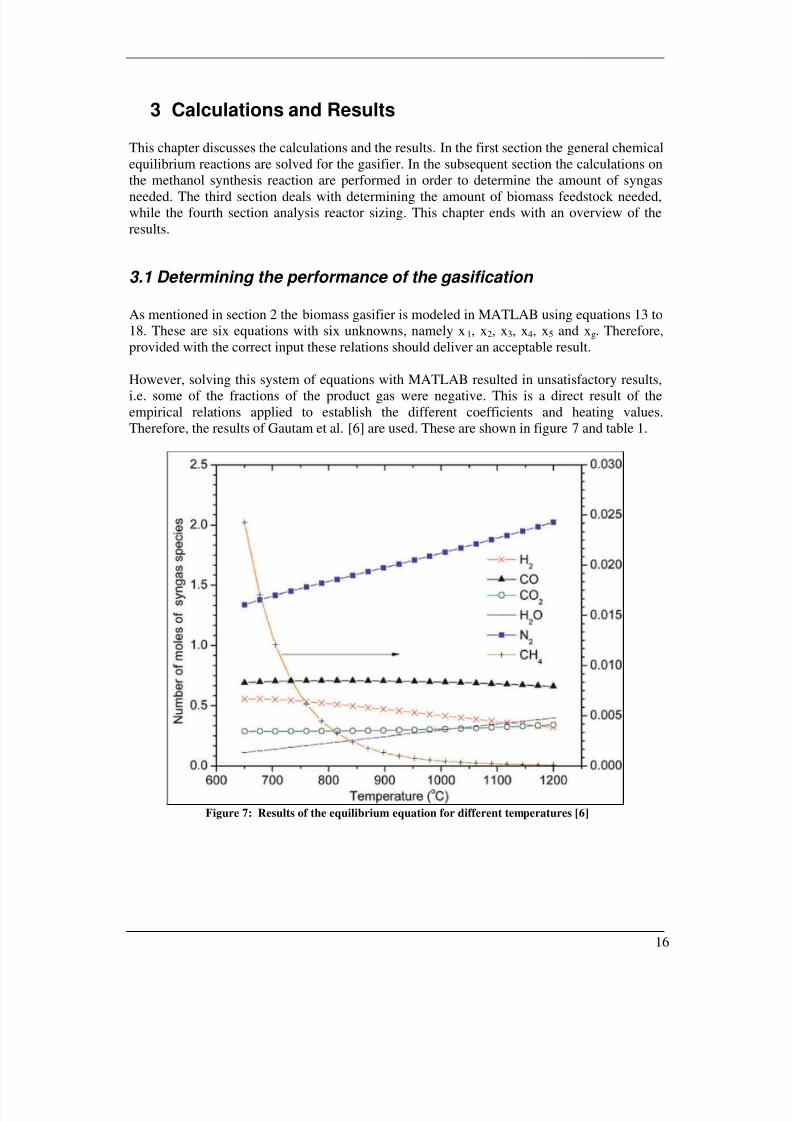
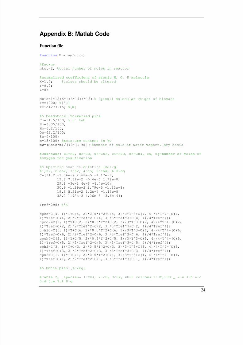
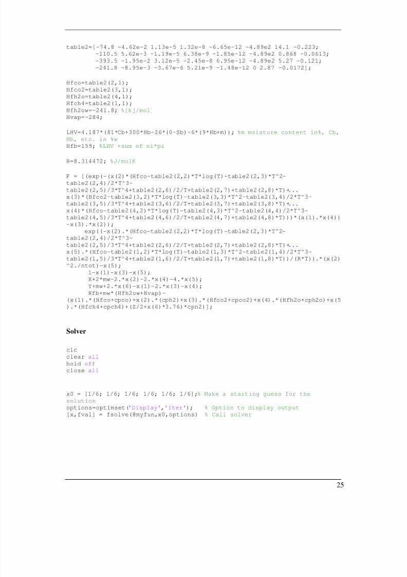
As mentioned in section 2 the biomass gasifier is modeled in MATLAB using equations 13 to
18. These are six equations with six unknowns, namely x1, x2, x3, x4, x5 and xg. Therefore,
provided with the correct input these relations should deliver an acceptable result.
However, solving this system of equations with MATLAB resulted in unsatisfactory results,i.e. some of the fractions of the product gas were negative. This is a direct result of the
empirical relations applied to establish the different coefficients and heating values.
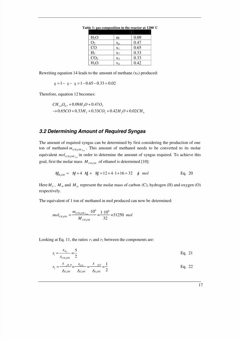
Therefore, the results of Gautam et al. [6] are used. These are shown in figure 7 and table 1.
Figure 7: Results of the equilibrium equation for different temperatures [6]
Apart from biomass feedstock, also oxygen and water (steam) are fed into the reactor. For
oxygen the molar value can be calculated as:
1.4 0.7
2
9( )
( )
59.18 10 0.47882 /
365 24 3600 365 24 3600
tot
tot
CH O g
O
mol xmol mol s
⋅ ⋅ ⋅= = =
⋅ ⋅ ⋅ ⋅Eq. 32
The reason for expressing the molar value of the fed O2 in seconds will become clear in the
next section. The mass of the fed O2 can then be determined as follows:
2 2
2
( ) 882 2 1628.2 /
1000 1000
tot O O
O
mol M m kg s
⋅ ⋅ ⋅= = = Eq. 33
The same can be done for the water (steam) being fed into the reactor:
1.4 0.7
2
9( )
( )
59.18 10 0.09168.9 /
365 24 3600 365 24 3600
tot
tot
CH O
H O
mol mmol mol s
⋅ ⋅ ⋅= = =
⋅ ⋅ ⋅ ⋅Eq. 34
( )2 2
2
( ) 168.9 2 1 163.04 /
1000 1000
tot H O H O
H O
mol M m kg s
⋅ ⋅ ⋅ += = =
Now that the molar and mass values of the components being fed into the reactor are known,
the dimensioning of the reactor can be performed.
3.4 Determining the Size of the gasification reactor
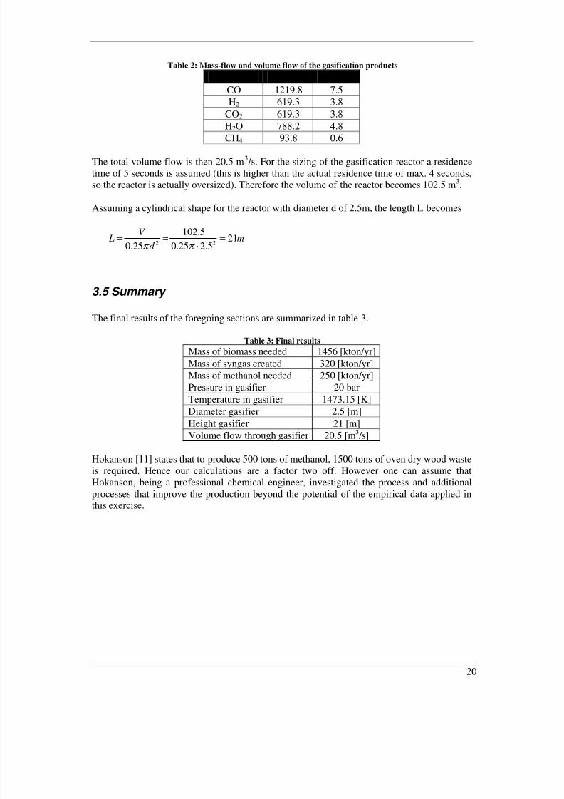
The residence time of the reaction products is 0.5 to 4 s, as mentioned in chapter 1. Thevolume of the products per second can be obtained by summing the volume of the initial
products.
The mass flow of the initial products is calculated as follows:
1.4 0.7( )
365 24 3600
tot CH O i
i
mol xm
⋅=
⋅ ⋅ɺ Eq. 35
This can now be converted to a volume flow using
,i U im R T V P
=ɺ Eq. 36
The temperature and pressure used in this equation are the temperature and pressure of the
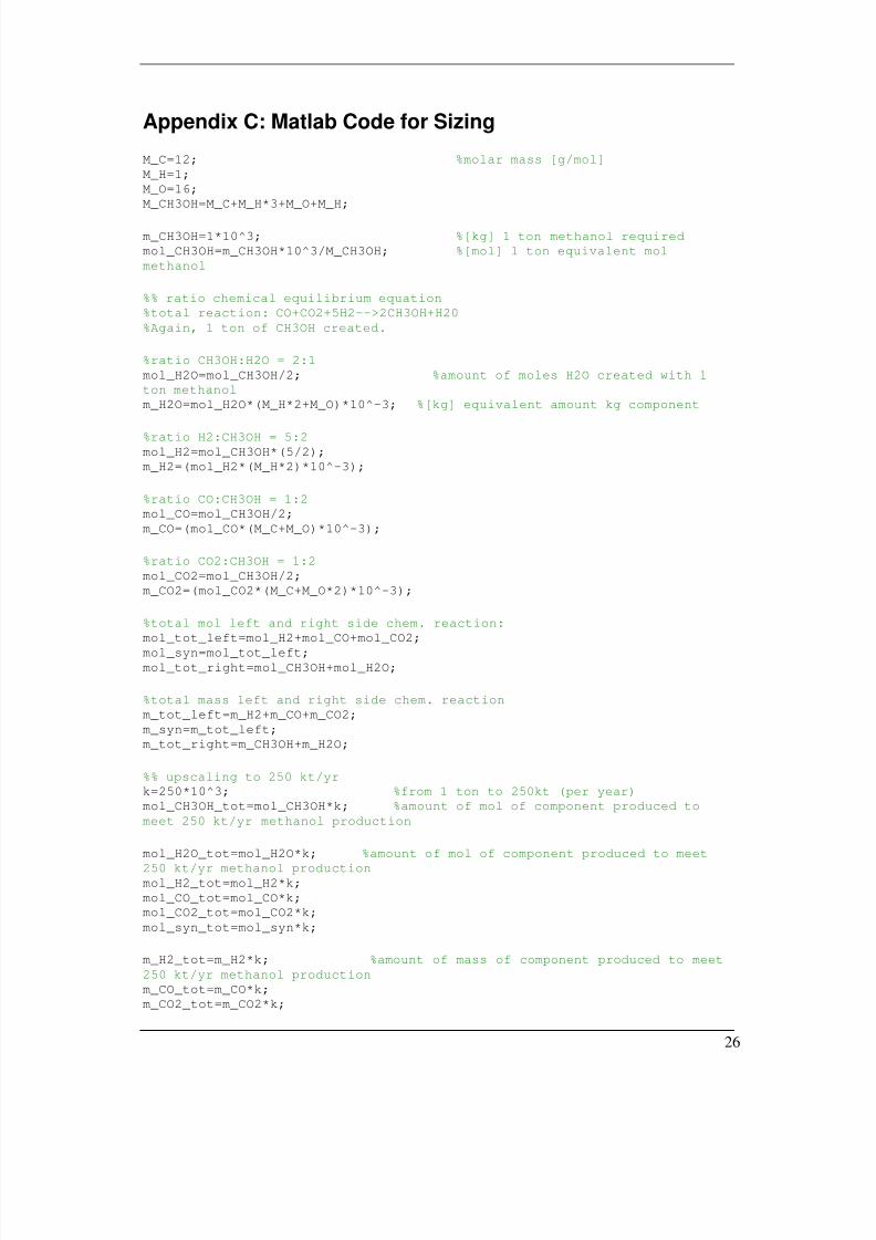
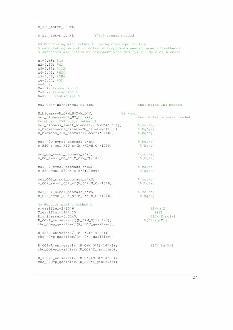
%% Continuing with method b (using chem equilibrium) % calculating amount of moles of components needed based on methanol % synthesis and ratios of component when gasifying 1 mole of biomass
x1=0.65; %CO x2=0.33; %H2 x3=0.33; %CO2 x4=0.42; %H2O x5=0.02; %CH4 xg=0.47; %O2 m=0.09; X=1.4; %subscript H Y=0.7; %subscript O Z=0; %subscript N