36
Setting Up Chromeleon PA (Includes Chromeleon PA OPC Interface Setup) Document No. 065262 Revision 03 October 2013

Setting Up Chromeleon PA(Includes Chromeleon PA OPC Interface Setup)
Document No. 065262Revision 03
October 2013

© 2013 by Thermo Fisher Scientific Inc. All rights reserved.
Chromeleon PA is a registered trademark of Thermo Fisher Scientific Inc. in the United States.
OPC is a trademark of OPC Foundation.
All other trademarks are the property of Thermo Fisher Scientific and its subsidiaries.
Thermo Fisher Scientific Inc. provides this document to its customers with a product purchase to use in the product operation. This document is copyright protected and any reproduction of the whole or any part of this document is strictly prohibited, except with the written authorization of Thermo Fisher Scientific Inc.
The contents of this document are subject to change without notice. All technical information in this document is for reference purposes only. System configurations and specifications in this document supersede all previous information received by the purchaser.
Thermo Fisher Scientific Inc. makes no representations that this document is complete, accurate or error-free and assumes no responsibility and will not be liable for any errors, omissions, damage or loss that might result from any use of this document, even if the information in the document is followed properly.
This document is not part of any sales contract between Thermo Fisher Scientific Inc. and a purchaser. This document shall in no way govern or modify any Terms and Conditions of Sale, which Terms and Conditions of Sale shall govern all conflicting information between the two documents.
Revision history: Revision 01 released November 2008Revision 02 released September 2010Revision 03 released October 2013
For Research Use Only. Not for use in diagnostic procedures.

Doc. 065262-03 10/13 iii
Chromeleon PA Setup Instructions . . . . . . . . . . . . . . . . . . . 1
1. About Chromeleon PA . . . . . . . . . . . . . . . . . . . . . . . . . . . . . . . . . . . . . . 1
2. The Chromeleon PA Folder Structure . . . . . . . . . . . . . . . . . . . . . . . . . . . 3
3. System Requirements . . . . . . . . . . . . . . . . . . . . . . . . . . . . . . . . . . . . . . . 3
4. Setup Procedure Overview . . . . . . . . . . . . . . . . . . . . . . . . . . . . . . . . . . . 4
5. Running the Setup Programs and Entering License Information . . . . . . 5
6. Creating Systems and Configuring Devices . . . . . . . . . . . . . . . . . . . . . . 5
7. Opening a Control Panel . . . . . . . . . . . . . . . . . . . . . . . . . . . . . . . . . . . . . 8
8. Creating Program (PGM) Files . . . . . . . . . . . . . . . . . . . . . . . . . . . . . . . . 9
8.1 Creating Programs for Different System Functions . . . . . . . . . . 9
8.2 Viewing Example Programs . . . . . . . . . . . . . . . . . . . . . . . . . . . 10
9. Creating Method (QNT) Files . . . . . . . . . . . . . . . . . . . . . . . . . . . . . . . . 10
10. Creating Report Definition Files (RDF) . . . . . . . . . . . . . . . . . . . . . . . . 12
10.1 Report Types . . . . . . . . . . . . . . . . . . . . . . . . . . . . . . . . . . . . . . 12
10.2 Example Reports . . . . . . . . . . . . . . . . . . . . . . . . . . . . . . . . . . . 12
11. Starting the Analyzer Program . . . . . . . . . . . . . . . . . . . . . . . . . . . . . . . 13
12. Connecting to the Datasource . . . . . . . . . . . . . . . . . . . . . . . . . . . . . . . . 13
13. Connecting to the Instrument Server . . . . . . . . . . . . . . . . . . . . . . . . . . . 13
14. Configuring Analyzers, Systems, and Streams . . . . . . . . . . . . . . . . . . . 14
Contents

Setting Up Chromeleon PA
iv Doc. 065262-03 10/13
A • The Chromeleon PA OPC Interface . . . . . . . . . . . . . .19
A.1 Data Access (DA) User Interface . . . . . . . . . . . . . . . . . . . . . . . . . . . . . .19
A.2 States and Commands . . . . . . . . . . . . . . . . . . . . . . . . . . . . . . . . . . . . . . .26
A.2.1 Analyzer.Command and Sequence. . . . . . . . . . . . . . . . . . . . . . .27
A.2.2 Analyzer.State . . . . . . . . . . . . . . . . . . . . . . . . . . . . . . . . . . . . . .28
A.2.3 System.State . . . . . . . . . . . . . . . . . . . . . . . . . . . . . . . . . . . . . . . .29
A.2.4 System.Command. . . . . . . . . . . . . . . . . . . . . . . . . . . . . . . . . . . .29
A.3 End of Sample and Data Ready Notification . . . . . . . . . . . . . . . . . . . . .30
A.4 Remote Access . . . . . . . . . . . . . . . . . . . . . . . . . . . . . . . . . . . . . . . . . . . .31

Doc. 065262-03 10/13 1
Chromeleon PA Setup Instructions
1. About Chromeleon PA
Thermo Scientific Dionex™ Chromeleon™ PA is a client/server-based chromatography management system that provides software control of Integral analyzers or bench-top migration systems used for process analytical applications. An analyzer is a group of chromatography systems that operate synchronously to analyze a series of process sample streams. Chromeleon PA can control a total of four chromatography systems configured in up to four analyzers.
Chromeleon PA is an extended version of the Thermo Scientific Dionex Chromeleon Chromatography Management System (Chromeleon). Chromeleon PA adds process monitoring functions (including stream selection, sample preparation, alarm configuration, and component data trending) to Chromeleon.
These are the Chromeleon PA main components:
• Chromeleon Server Configuration program—maintains configuration information about the chromatography instrument systems. This is a standard component of Chromeleon.
• Chromeleon Instrument Server—controls the data exchange between Thermo Scientific Dionex™ Integral Process Analytical Systems and the Chromeleon PA computer.
• Chromeleon Server Monitor program—required for starting and monitoring the chromatography server. This is a standard component of Chromeleon.
• Chromeleon client—the user interface for accessing chromatography data and for controlling individual chromatography instruments. This is a standard component of Chromeleon.
• Analyzer program—the user interface for accessing process analytical functions. This includes all analyzer-level configuration, analyzer control, results display, and results reporting. This is a unique component of Chromeleon PA.

Setting Up Chromeleon PA
2 Doc. 065262-03 10/13
• Analyzer device driver—transfers analyzer status and events from Chromeleon PA to Chromeleon. This is a unique component of Chromeleon PA.
• Datasource—the database in which Chromeleon PA data is stored. The structure of this database is a unique component of Chromeleon PA (see Section 2).
• Chromeleon PA OPC™ Interface (Optional)—the Chromeleon PA OPC (OLE for Process Control) Server allows access to, and limited control of, one or more Dionex Integral analyzers by an external OPC-compatible program (the client). The OPC client uses Dionex Integral analyzer data for custom applications. The Chromeleon PA OPC interface specifications are based on the Axeda FactorySoft OPC Toolkit.
The above programs, as well as the datasource and instrument server can be installed on a single computer or on separate computers, as in the following example:
Chromeleon Client
Analyzer Program
Datasource
Integral Process Analytical System
Networked Chromeleon PA Components
Instrument Server

The Chromeleon PA Folder Structure
Doc. 065262-03 10/13 3
2. The Chromeleon PA Folder Structure
Unlike Chromeleon, which can be connected to multiple datasources, Chromeleon PA can be attached to only one datasource at a time. All data (including sample data, the Chromeleon Audit Trail, report templates, alarm configurations, and so on) is stored and retrieved from this datasource. Chromeleon PA creates the folder structure of the datasource.
When you configure timebases (systems) in the Server Configuration program, Chromeleon creates a top-level folder in the datasource for each configured system. All programs (PGM files), methods (QNT files), and report templates (RDF files) for a system must be stored in this top-level folder. These are the templates used in daily operation as described below.
During daily operation, when the analyzer begins the first sequence of the day, Chromeleon PA creates a new folder under the system top-level folder and names it with
the current year, month, and day. All sequences started on that day are then placed in this subfolder. Each sequence is named with a 6-digit number to ensure uniqueness. Output PGM and QNT files, which are copied from the template versions located in the top-level folder, are also stored in the sequence folder.
3. System Requirements
System requirements for Chromeleon PA are the same as for Chromeleon versions without process monitoring functions. Refer to Installing the Chromeleon IC System (Document No. 031883) for details.
Chromeleon PA Datasource Folder Structure
Sequences for the day
PGM, QNT, and RDF files for the system* andChromeleon daily Audit Trails
Raw data. Plus PGM and QNT files** for this sequence
System_2
System_1
000000
000002
000001
YYYY-MM-DD
*These files are used as templates.**Copies of the system template files are created for each sequence.

Setting Up Chromeleon PA
4 Doc. 065262-03 10/13
4. Setup Procedure Overview
This section provides an overview of the tasks that must be completed before you can begin using Chromeleon PA to control a Dionex Integral analyzer.
1. Run the Chromeleon and Chromeleon PA setup programs, enter the license information, and connect the chromatography system devices (see Section 5).
2. In the Server Configuration program, create timebases (systems) and configure the system devices (see Section 6).
3. In the Chromeleon client, open control panels for each system. Verify that Chromeleon is communicating with all systems and the systems are functioning correctly (see Section 7).
4. In the Chromeleon client, create programs (see Section 8), quantification methods (see Section 9), and report definitions (see Section 10). Save all files in the top-level system folder in the datasource.
5. Start the Analyzer program and connect to the datasource in which the program, method, and report files for the analyzer systems are stored (see Section 12).
6. In the Analyzer program, connect to the Chromeleon instrument server that controls the analyzer systems (see Section 13).
7. In the Analyzer program, configure analyzers, systems, and streams (see Section 14).
8. (Optional) Run the Chromeleon PA OPC interface setup program and then follow the instructions in Appendix A to set up the interface.

Running the Setup Programs and Entering License Information
Doc. 065262-03 10/13 5
5. Running the Setup Programs and Entering License Information
Follow the instructions in Installing the Chromeleon Chromatography Management System (Document No. 031883) to complete the following steps:
1. Insert the Chromeleon disk in the computer and run the Chromeleon Setup program.
2. Install any appropriate Chromeleon Service Packs. Refer to the release notes for the latest information.
3. When Chromeleon setup is complete, insert the Chromeleon PA disk in the computer and run the Chromeleon PA setup.
4. Start the Chromeleon server.
5. Enter the license information.
6. Connect the chromatography system devices to the Chromeleon network.
6. Creating Systems and Configuring Devices
Before you can operate a Dionex Integral analyzer, Chromeleon PA needs to know the system configuration (which hardware devices are to be controlled and how they are connected). The number of systems needed and the devices included in each depend on your hardware devices and the applications to be run. In addition to the hardware devices, each system configuration must include (or share) an Analyzer device.
1. Make sure all chromatography system devices are connected to the Chromeleon network and their power is turned on.
2. Open the Chromeleon Server Configuration program and create the systems required for your hardware configuration.
3. Add the hardware devices to each system.
4. Add an Analyzer device to each system or share the Analyzer device between up to four systems. Systems that share an Analyzer device will be configured into one analyzer in the Analyzer program. Systems that do not share an Analyzer device will be configured into separate analyzers.
In the example configuration shown below, two chromatography systems are sharing an Analyzer device. When you configure analyzers in the Analyzer

Setting Up Chromeleon PA
6 Doc. 065262-03 10/13
program (see Section 14), these two systems will be configured into one analyzer.
5. When you add a device to a timebase, enter the configuration properties as required for the device. Click the Help button on each tab page for details about the properties on the page.

Creating Systems and Configuring Devices
Doc. 065262-03 10/13 7
6. If you are configuring an SP1 or SP2, rename the generic solenoid valve names on the Solenoids page to match the names and functions assigned to the valves in the SP1 and SP2. Type the names exactly as shown in the following example. This ensures that solenoid valve controls on the Chromeleon Control panel will be enabled.
Setting Up Chromeleon PA
8 Doc. 065262-03 10/13
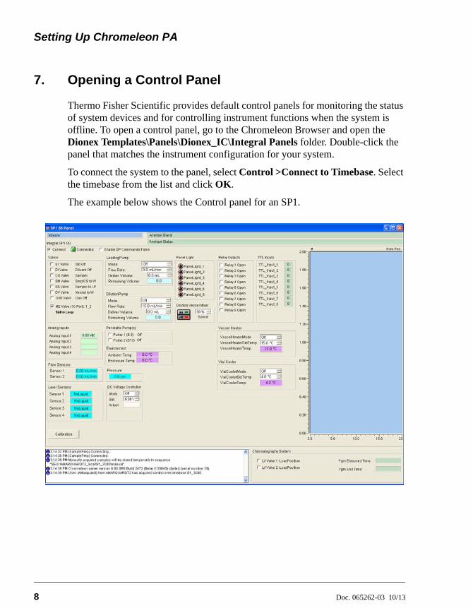
7. Opening a Control Panel
Thermo Fisher Scientific provides default control panels for monitoring the status of system devices and for controlling instrument functions when the system is offline. To open a control panel, go to the Chromeleon Browser and open the Dionex Templates\Panels\Dionex_IC\Integral Panels folder. Double-click the panel that matches the instrument configuration for your system.
To connect the system to the panel, select Control >Connect to Timebase. Select the timebase from the list and click OK.
The example below shows the Control panel for an SP1.

Creating Program (PGM) Files
Doc. 065262-03 10/13 9
8. Creating Program (PGM) Files
In the Chromeleon client, use the Program Wizard to create new program files for the analyzer systems or to edit existing programs. See the Chromeleon Help for detailed instructions.
When you save the programs, save them in the top-level folder of the system for which the program was created. The Analyzer program only accesses programs from this top-level folder. If the files are in a different folder, they will not be available in the Analyzer program. See Section 2 for details about the Chromeleon PA folder structure.
In the example below, two programs were created for the S1_3000 system and saved in the system’s top-level folder.
8.1 Creating Programs for Different System Functions
In addition to creating programs for sample analyses, you can also create programs to control other system functions (for example, shutting down a system). The Analyzer program lets you assign the following four types of programs to a system:
Program Type Used For
Default Running sample analyses
Standby Placing a system in standby
Shutdown Shutting down a system
Overlap Flush Flushing when a sequence is interrupted (for example, if an alarm occurs)
Top-LevelSystemFolder
ProgramFiles

Setting Up Chromeleon PA
10 Doc. 065262-03 10/13
The Chromeleon Program Wizard is designed primarily for creating programs for data acquisition. Data acquisition commands cannot be used with the Standby, Shutdown, and Overlap Flush programs.
When you use the Program Wizard to create a Standby, Shutdown, or Overlap Flush program, delete any detector signal-related commands from the program after completing the Wizard. Examples of lines to delete are:
• Autozero
• ECD_1.AcqOn
• ECD_1.AcqOff
• UV.AcqOn
• UV.AcqOff
8.2 Viewing Example Programs
Chromeleon PA provides example program files, which you can refer to when creating programs for your analyzer. Because every program is created for a specific system and application, the examples will not work “as is” with your analyzer, but the principles behind the types of commands included and the order in which they are listed can be applied to many systems.
To access the example programs, go to the Chromeleon Browser and open the Dionex Templates\IC Applications\IC Integral Applications folder.
9. Creating Method (QNT) Files
In Chromeleon, create new method files or edit existing files. This section provides a brief description of the steps and settings recommended for creating QNT files for Chromeleon PA. Refer to the Chromeleon Help for detailed instructions.
After creating the QNT files, save them in the top-level system folder. These files will be used as templates by the Analyzer program. See Section 2 for details about the Chromeleon PA folder structure.

Creating Method (QNT) Files
Doc. 065262-03 10/13 11
Updating the Calibration
During daily operation, when the Analyzer program runs a sequence, it copies the template method (QNT) file from the system’s top-level program and saves it with the sequence. If a sequence includes calibration standards, both the sequence copy of the method and the template method are updated. This ensures that the updated calibration information is used for all subsequent sequence runs on that system.
When setting up method files for system calibration, you will need to create sequences in the Chromeleon client. However, for routine analyzer runs, the Analyzer program is used to create and control sequences.
Creating Method Files for Chromeleon PA
Complete the following steps in the Chromeleon client.
1. Create a new method file (select File>New>Method File) or copy one of the example files included in the Dionex Templates>IC Applications folders and modify it as required for your system.
2. In the QNT Editor, select the General tab page, and select the Fixed Mode under Global calibration settings.
3. Create a sequence that runs the desired number of levels and replicates of the calibration standards.
4. Run the standards.
5. In the QNT editor, select the Calibration tab and add the standards to the table (right-click and select Insert Standard).
6. On the Amount Table tab page, enter the amounts of the components in the standard.
7. On the General tab page, click the Calibrate button to generate the calibration curve and parameters.
8. Save the calibrated method file in the top-level folder for the system.

Setting Up Chromeleon PA
12 Doc. 065262-03 10/13
10. Creating Report Definition Files (RDF)
In Chromeleon, create report definition files to define the contents of reports printed from the Analyzer program. See the Chromeleon Help topic, “Report Templates” for detailed instructions.
As with program and method files, save all report files in the top-level folder of the system for which the report will be used.
10.1 Report Types
The following two basic types of reports are used with Chromeleon PA:
• Sample (end-of-run) reports print the results of sample analysis at the end of each injection run. These reports typically include a chromatogram, a table containing information (height, area, amount, etc.) about each peak in the chromatogram, calibration curves and tables, and peak analysis information (height, width, type, resolution, etc.).
• Scheduled (trend) reports print at scheduled intervals. These reports typically include trend data plots (for example, a plot of the peak height obtained for a particular component over the last 24 hours).
10.2 Example Reports
Chromeleon PA provides example reports, which you can copy to your system folders and modify for your needs. The report files are available in the Chromeleon Browser in the Dionex Templates>Reports folder.

Starting the Analyzer Program
Doc. 065262-03 10/13 13
11. Starting the Analyzer Program
Verify that the Chromeleon Server is running and then select Start>All Programs>Chromeleon>CM-PA.
12. Connecting to the Datasource
When the Analyzer program starts the first time, the Datasource dialog box appears. Under Available Datasources, select the datasource in which the analyzer system folders are located. Click Make Current.
13. Connecting to the Instrument Server
To connect to the Chromeleon instrument server, on the Administration menu, select Instrument Server. The Connect to Chromeleon Server dialog box appears. Select the server from the list and click OK.

Setting Up Chromeleon PA
14 Doc. 065262-03 10/13
14. Configuring Analyzers, Systems, and Streams
To configure analyzers, systems, and streams, follow the basic steps outlined below. For detailed instructions, refer to the Analyzer program Help.
1. Create one or more analyzers and assign the chromatography instrument systems to them. When creating new analyzers and assigning systems, make sure the configuration you create in the Analyzer program matches the configuration established in the Chromeleon Server Configuration program (see Section 6).
The example configuration shown below consists of one analyzer (Analyzer 1) that has two systems (S1_3000 and S2_3000) assigned to it. This configuration matches the example server configuration described in Section 6. In the server configuration, S1_3000 and S2_3000 share an Analyzer device, therefore they must be configured into the same analyzer in the Analyzer program.
Configuring Analyzers, Systems, and Streams
Doc. 065262-03 10/13 15
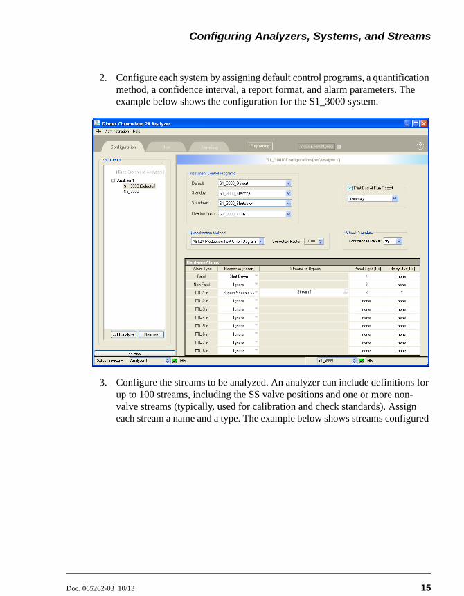
2. Configure each system by assigning default control programs, a quantification method, a confidence interval, a report format, and alarm parameters. The example below shows the configuration for the S1_3000 system.
3. Configure the streams to be analyzed. An analyzer can include definitions for up to 100 streams, including the SS valve positions and one or more non-valve streams (typically, used for calibration and check standards). Assign each stream a name and a type. The example below shows streams configured

Setting Up Chromeleon PA
16 Doc. 065262-03 10/13
for Analyzer_1. Streams 1 through 7 are the streams from each SS valve position.
4. Create sequences for various analyzer functions. The example below shows a sequence for running sample streams.

Configuring Analyzers, Systems, and Streams
Doc. 065262-03 10/13 17
5. Assign default sequences to four analyzer functions: (1) running samples (2) starting up (3) calibrating and (4) running check standards.
6. Define result-based events (events that are triggered if a result meets a pre-defined condition). In the example shown below, the check standard sequence is run if the retention time of the chloride peak exceeds 3.225.
NOTE In the above example, the left pane of the window (theconfiguration tree) is hidden.

Setting Up Chromeleon PA
18 Doc. 065262-03 10/13

Doc. 065262-03 10/13 19
A • The Chromeleon PA OPC Interface
OPC is a series of standards specifications that enables open connectivity in industrial automation1. The optional Chromeleon PA OPC Server includes the OPC Data Access (DA) interface specification2. This interface moves real-time data.
Installation of the Chromeleon PA OPC Server allows access to, and limited control of, one or more Dionex Integral Process Analytical Systems by an external OPC-compatible program (the client). The OPC client will use Integral data for custom applications.
This appendix contains the following sections:
Before beginning these tasks, run the Chromeleon PA OPC interface setup program.
A.1 Data Access (DA) User Interface
This section explains how to establish communication between the Integral analyzer and the OPC client and how to select DA tags and assign numeric values to them. A tag is any aspect of the analyzer or system that the OPC Server can monitor or control; this includes sequences, sample streams, device states, report variables, and status messages.
1. For more information about OPC, go to http://www.opcfoundation.org/.2. The Chromeleon PA OPC specification is based on the Axeda FactorySoft OPC Toolkit.
Section A.1 Instructions for setting up the OPC Data Access interface
Section A.2 Details about states and commands
Section A.3 Instructions for gathering results at the end of a sample
Section A.4 Instructions for setting up remote access of the OPC server

Setting Up Chromeleon PA
20 Doc. 065262-03 10/13
1. Start the Chromeleon Server and then start the Analyzer program (select Start>All Programs>Chromeleon>CM-PA).
2. Start the Chromeleon PA OPC Server (select Start>All Programs>Chromeleon>OPC Server). Each time the OPC Server is started, the list of tags is rebuilt. The time required to complete this process varies, depending on the number of tags. When the list is complete, the OPC icon appears on the taskbar.
3. When the OPC icon appears on the taskbar, start the OPC Data Access (DA) client (select Start>All Programs>Chromeleon>DA Client).
The main window of the DA client appears.
Notes:
• The Dionex DA client is simply an OPC test client; it provides access to the Chromeleon PA OPC Server and enables you to view certain features, but is not linked to any other programs.
• Typical OPC installations require the use of a “double-headed” client application that can be used to connect the Chromeleon PA OPC Server application to another server application.
4. On the OPC menu, select Connect.

The Chromeleon PA OPC Interface
Doc. 065262-03 10/13 21
The Connect to OPC Data Access Server dialog box appears.
5. Under Available servers, select CM.DA.1 (Dionex Chromeleon Data Access Server) and click OK.
6. On the OPC menu, select Add Item.

Setting Up Chromeleon PA
22 Doc. 065262-03 10/13
The Add Item dialog box appears. The following example shows the top level of the tag tree under Browse items. The default state is that no tags are selected.
The general structure for the tag tree is as follows:Root (tag: Poll)- CM Datasource- - General- - Analyzer (tags: Command, sequence, other)- - System (tags: data ready, end of sample, alarm LED states, TTL states, Relay states)- - - Sample stream- - - - Detector- - - - - Analyte- - - - - - peak results (tags: area, amount, height, etc.)
To expand the tree, click the + sign preceding an item.

The Chromeleon PA OPC Interface
Doc. 065262-03 10/13 23
7. To add a tag, select an item in the Browse items tree. A list of related tags is displayed to the right. See the following example.
8. Select a tag and click Add Item. To view additional information about a selected tag, click the Item Properties button.
NOTE For an explanation of which tags to select to gatherresults at the end of a sample, see Section A.3.
9. When you finish adding tags, click Done.

Setting Up Chromeleon PA
24 Doc. 065262-03 10/13
10. The main window of the DA client now displays the tags you selected. The window will resemble the following example.
NOTE If the quality of a selected tag is “Uncertain,” refer to the“Category Tables” section on the following page formore information.
11. To retain this list of tags for use in the future (and avoid repeating the selection process), select Save on the File menu. Select a path and name for the configuration file and click OK.
12. Select any tag with write permission (as indicated in the Access column). On the OPC menu, select Write Value to Item.
The Write Value to dialog box appears.
13. After referring to the tables in Section A.2, type an appropriate value for the tag and click OK.
NOTE Do not select the Asynchronous check box.

The Chromeleon PA OPC Interface
Doc. 065262-03 10/13 25
14. Continue assigning values to tags in the DA client window.
General Notes
Poll: A Poll tag is provided as a “heartbeat” from CM-OPC server. It is an integer value incremented on each poll of about 1 second. It begins at 0 at CM OPC Server startup.
“n.a.” Results: Under certain circumstances, numerical results will return the text “n.a.” (For example, if a peak is not found, the Amount is returned as n.a.) If this occurs, the numerical results are converted to the minimum negative value of the type (floating point = -2.2250738585072014e-308, integer = -2147483648) and the quality of the tag is set to OPC_QUALITY_UNCERTAIN.
NOTE The variable value is not converted to the minimumnegative value of the type.
To determine the actual value returned by Chromeleon, look at the table tag:
1. Select the tag name in the DA client window.
2. On the Edit menu, select Copy (or press Ctrl-C).
3. Paste the contents of the table into Notepad (or other text editor). Scroll through the file to the tag of interest.
CM-PA Close and Restart
Closing CM-PA will cause the Chromeleon-PA status text to indicate “CM-PA not available.” The stream tag quality will be set to bad. OPC results acquisition and symbol table states will continue to function but analyzer and system states and commands will indicate out of range error codes.
If CM-PA is restarted with no errors or configuration changes, the Chromeleon-PA status text will indicate “OK.” The stream tag quality will be set to good.
NOTE CM-PA closing is detected using a remoting exception,an inter-process communication error betweenCMOPC.EXE and CM-PA.EXE.
CM Server Stop
If connection to the CM Server fails, the System status tag text is as follows: “Symbol Table: XML element invalid.” The CM Server and then the OPC server must be restarted to restore the connection.

Setting Up Chromeleon PA
26 Doc. 065262-03 10/13
A.2 States and Commands
Essentially all control for the chromatography system is at the “Analyzer Command” level. Likewise, general status is found at the “Analyzer Status” level. Keep in mind that an “analyzer” is one or more chromatography systems running in parallel, performing a determination (or determinations) on a sample. When all chromatography systems that are configured into one Analyzer are finished, the Analyzer moves on to the next sample. Many installations only consist of one system. In these cases it might seem confusing to run at the analyzer level, but in order to accommodate sample stream selection, automatic sequence generation, conditional logic, and other CM-PA features, operation is maintained at the analyzer level.
To start the analyzer:
1. Set the Sequence name (string) (see Section A.2.1). Note that a sequence equals the list of, or order of samples. This analyzer sequence must be pre-defined in CM-PA and the string that is entered in OPC must match the name defined in CM-PA.
2. Set the Analyzer Command tag to 0 (start)
NOTE If the analyzer sequence consists of one line (one samplestream), the Start command will only run one sample. Torun another sample, the start command will need to besent again.

The Chromeleon PA OPC Interface
Doc. 065262-03 10/13 27
A.2.1 Analyzer.Command and Sequence
Command Code Definition
Start 0 Use in conjunction with analyzer-level sequence tag. The sequence tag is assigned a sequence, and then the analyzer command is set to 0.
Sequence End 1 End current sequence at end of sequence (stop looping).
Sample End 2 End current sequence at end of currently running sample.
Abort 3 Abort current sequence immediately.
Resume 4 Restart systems in standby.
Standby End of Sequence
5 Put analyzer into standby at end of sequence.
Standby End of Sample
6 Put analyzer into standby at end of sample.
Standby 7 Put analyzer into standby immediately.
Sequence string Sequence name as an alpha-numeric string. Can be a word, integer, or combination. Enter the sequence that is to be started. If no sequence is entered, the default sequence is run.

Setting Up Chromeleon PA
28 Doc. 065262-03 10/13
A.2.2 Analyzer.State
These codes are the values provided to the OPC Server from CM-PA.
Analyzer State Code Definition
Ready 1 Analyzer ready to run.
Running 2 Analyzer running sequences.
Standby 3 All channels are in standby state. If standby methods were assigned, they are run or are being run.
Standard 4 Running calibration sequences.
Validate 5 Running check standard sequences.
Alarm Schedule 6 Running alarm schedule.
Re-run 8 Re-running sample.
Running RBE Sequence
9 Running result-based event sequence.

The Chromeleon PA OPC Interface
Doc. 065262-03 10/13 29
A.2.3 System.State
A.2.4 System.Command
System State Code Description
Ready 1 Sequence is not running.
Running 2 Sequence is running.
Standby 3 System is in standby state.
Shutdown 7 System shutdown, or not available.
Standard 4 Running calibration.
Validate 5 Running check standard.
Re-run 8 Re-running sample.
Running RBE Sequence
9 Running result-based event sequence.
Command Code Definition
Sequence End 1 End system sampling at end of sequence (stop looping).
Sample End 2 End system sampling at end of currently running sample.
Abort 3 Abort system sampling immediately.
Resume 4 Restart system if in standby.
Standby End of Sequence
5 Put system into standby at end of sequence.
Standby End of Sample
6 Put system into standby at end of sample.
Standby 7 Put system into standby immediately.

Setting Up Chromeleon PA
30 Doc. 065262-03 10/13
A.3 End of Sample and Data Ready Notification
End of Sample and Data Ready provide notification that Chromeleon has finished processing raw chromatographic data and has updated reported results. This includes reporting SST results, validation, standard pass/fail, and component alarms.
NOTE These tags are provided at the chromatography systemlevel.
End of Sample Tag (read only)
The End of Sample tag provides text in the following CSV format:
First row: Fixed header column
Second row: Actual data for each column
Example:
“Analyzer Name”, “System Name”, “Sample Name”, “Inj. Time”, “Event”, <CR>“analyzer 1”, “system 1”, “sample 1”, “11-30-08 11:21:34”, <Code>
Where <CR> is a new line; <Code> is the end of sample code; 1 is a sample ended normally. Any other value for <Code> indicates a premature termination of the sample and sequence. Results for the terminated sample will not be updated. The end of a standby method is indicated by empty entries for the sample name and injection time.
Data Ready Tag (read/write)
A “data ready” tag is provided at the system level as a read/write string. The value is equal to the <code> from the end of the End of Sample tag. However, this is a simplified tag with read/write attributes. A value “1” means sample ended normally; other values mean a premature termination. It is meant to provide a resettable tag that can be monitored by a remote control client. The tag type is a string. The typical value to reset is “0.”
Test Results Tags
The Test Results tags in the System Suitability Row (num) categories within the System Suitability group provide result text in the following CSV format:
First row: Fixed header column
Second row: Actual data for each column

The Chromeleon PA OPC Interface
Doc. 065262-03 10/13 31
Example:
"Sample Name","Component Name","Category Name", "Result Name", Result", <CR>
"Standard 1",""," system suitability test Row 4"," Test Results"," Failed"
Where <CR> is a new line
A.4 Remote Access
The OPC client can access the server remotely from another computer, provided that the computer name is specified at connection time. Follow the steps below to correctly configure DCOM.
1. Launch DCOMCNFG.EXE (in WINDOWS\SYSTEM32).
2. Select the following settings on the respective property pages.
Default Properties
X Enable Distributed COM on this computer
Default Authentication Level: None
Default Impersonation Level: Impersonate
Default Security
Default Access Permissions
• Add the client computer
• Type of Access: Allow Access
Default Launch Permissions
• Add the client computer
• Type of Access: Allow Launch
Default Configuration Permissions
• Add the client computer
• Type of Access: Full Control

Setting Up Chromeleon PA
32 Doc. 065262-03 10/13
Properties
OPCENUM & DA and AE
• General: Authentication Level; Default
• Location: Run application from this location. CLEAR OTHER OPTIONS!
• Security: Accept defaults (OPCENUM and DA only)
• Identity: The launching user (OPCENUM and DA only)


