Setting up the Raspberry Pi Software (Windows) Installing the Raspbian OS 1. On your PC, navigate to http://downloads.raspberrypi.org/raspbian_latest. This will prompt you to download a file with a name like “2015-05-05-raspbian-wheezy.zip.” This file is ~1 GB, so it may take a while to download. 2. Once downloaded, unzip the file by double-clicking on it. This should create a file with the same name, but with a .img extension instead of a .zip. 3. Insert the microSD card into your PC using the MicroSD Adaptor. If you do not have an SD card reader on your computer, you will have to use an SD adaptor in a USB port. Note which drive letter was assigned (for example G:) when the card is inserted. You can check this in left column of Windows Explorer. 4. Download the Win32DiskImager utility from http://sourceforge.net/projects/win32diskimager/ 5. Run the installation executable (.exe) file. 6. Run the Win32DiskImager utility (program) as an administrator (right click then select “Run as administrator”). 7. Navigate to and select the .img file extracted in step 2. The file you selected will be displayed in the Image File textbox. 8. Under the “Device” dropdown menu, select the drive letter for the MicroSD card noted in step 3. WARNING: be careful to select the correct drive as selecting the wrong one can destroy data on your computer’s hard disk. 9. Click “Write” and wait for the write to complete 10. Exit Win32DiskImager and eject the SD card. 11. Good job! You have now installed an operating system on the SD card. You may now insert the SD card into the Raspberry Pi. Connect to the Raspberry Pi through Your Computer 1. Plug in the Edimax W-iFi USB adaptor into a USB port of your Raspberry Pi
Transcript
Setting up the Raspberry Pi Software (Windows)
Installing the Raspbian OS 1. On your PC, navigate to http://downloads.raspberrypi.org/raspbian_latest. This will prompt you
to download a file with a name like “2015-05-05-raspbian-wheezy.zip.” This file is ~1 GB, so it
may take a while to download.
2. Once downloaded, unzip the file by double-clicking on it. This should create a file with the same
name, but with a .img extension instead of a .zip.
3. Insert the microSD card into your PC using the MicroSD Adaptor. If you do not have an SD card
reader on your computer, you will have to use an SD adaptor in a USB port. Note which drive
letter was assigned (for example G:) when the card is inserted. You can check this in left column
of Windows Explorer.
4. Download the Win32DiskImager utility from http://sourceforge.net/projects/win32diskimager/
5. Run the installation executable (.exe) file.
6. Run the Win32DiskImager utility (program) as an administrator (right click then select “Run as
administrator”).
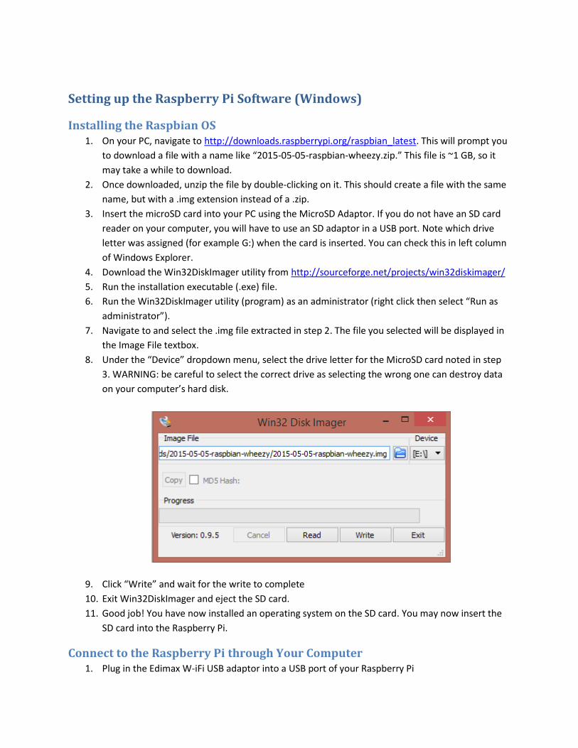
7. Navigate to and select the .img file extracted in step 2. The file you selected will be displayed in
the Image File textbox.
8. Under the “Device” dropdown menu, select the drive letter for the MicroSD card noted in step
3. WARNING: be careful to select the correct drive as selecting the wrong one can destroy data
on your computer’s hard disk.
9. Click “Write” and wait for the write to complete
10. Exit Win32DiskImager and eject the SD card.
11. Good job! You have now installed an operating system on the SD card. You may now insert the
SD card into the Raspberry Pi.
Connect to the Raspberry Pi through Your Computer 1. Plug in the Edimax W-iFi USB adaptor into a USB port of your Raspberry Pi
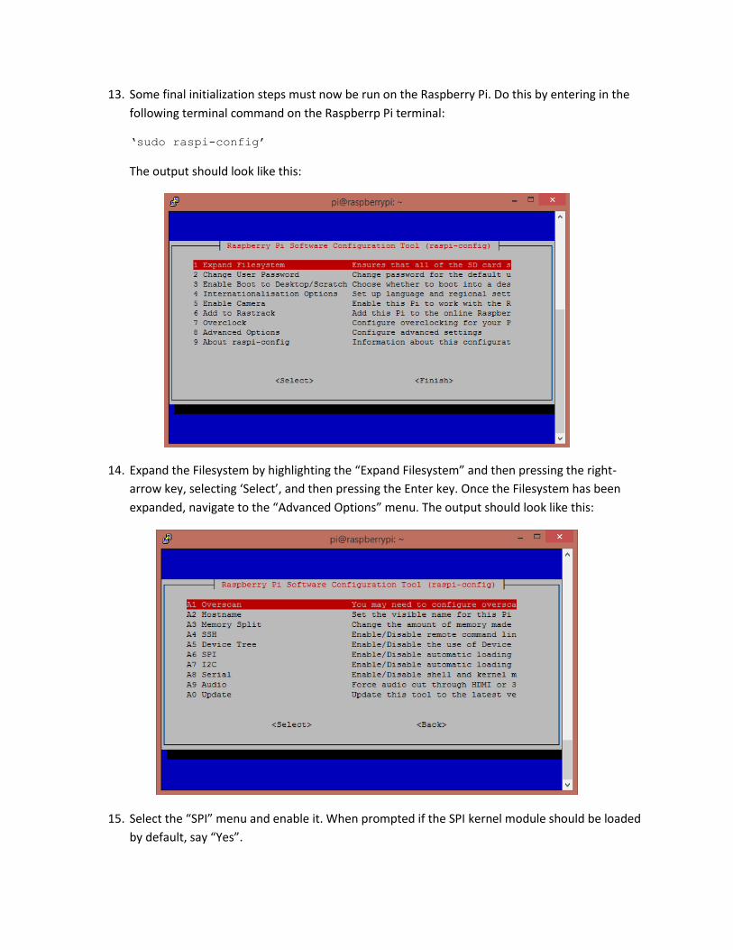
13. Some final initialization steps must now be run on the Raspberry Pi. Do this by entering in the
following terminal command on the Raspberrp Pi terminal:
‘sudo raspi-config’
The output should look like this:
14. Expand the Filesystem by highlighting the “Expand Filesystem” and then pressing the right-
arrow key, selecting ‘Select’, and then pressing the Enter key. Once the Filesystem has been
expanded, navigate to the “Advanced Options” menu. The output should look like this:
15. Select the “SPI” menu and enable it. When prompted if the SPI kernel module should be loaded
by default, say “Yes”.
16. Exit the setup menu by selecting “Finish”. When prompted to reboot, select “Yes”. This will
cause the Raspberry Pi to reboot, which will automatically end your PuTTY session.
Obtaining Software Packages to Run the EMG Acquire Software The EMG Acquire software requires some optional software to be installed. This can be done by running
one of the scripts contained in the ‘scripts.zip’ file provided with this tutorial. To run this script on the
Raspberry Pi, it must first be transferred to the Raspberry Pi from your PC. You will do this using the
Cyberduck program from here: https://cyberduck.io/
1. Make sure that your Raspberry Pi is connected to your router and is powered on.
2. Make sure that your PC is connected to the same router.
3. Make sure that your router has internet access.
4. Obtain the IP address of your Raspberry Pi using the techniques described in the previous
section. (If you haven’t changed your setup, it’s probably OK to assume that the IP address
hasn’t changed).
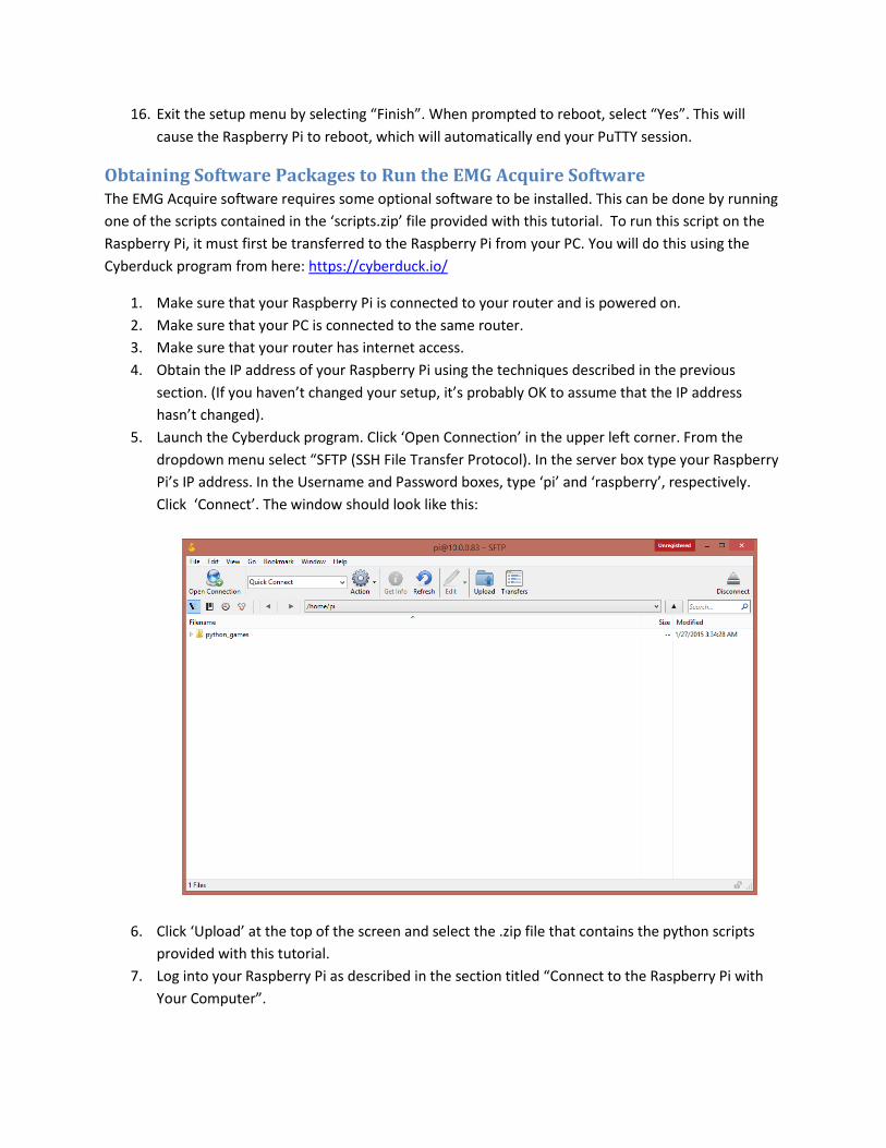
5. Launch the Cyberduck program. Click ‘Open Connection’ in the upper left corner. From the
dropdown menu select “SFTP (SSH File Transfer Protocol). In the server box type your Raspberry
Pi’s IP address. In the Username and Password boxes, type ‘pi’ and ‘raspberry’, respectively.
Click ‘Connect’. The window should look like this:
6. Click ‘Upload’ at the top of the screen and select the .zip file that contains the python scripts
provided with this tutorial.
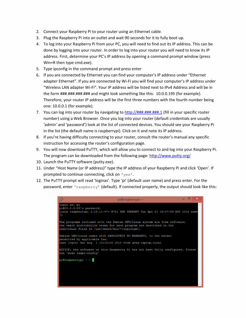
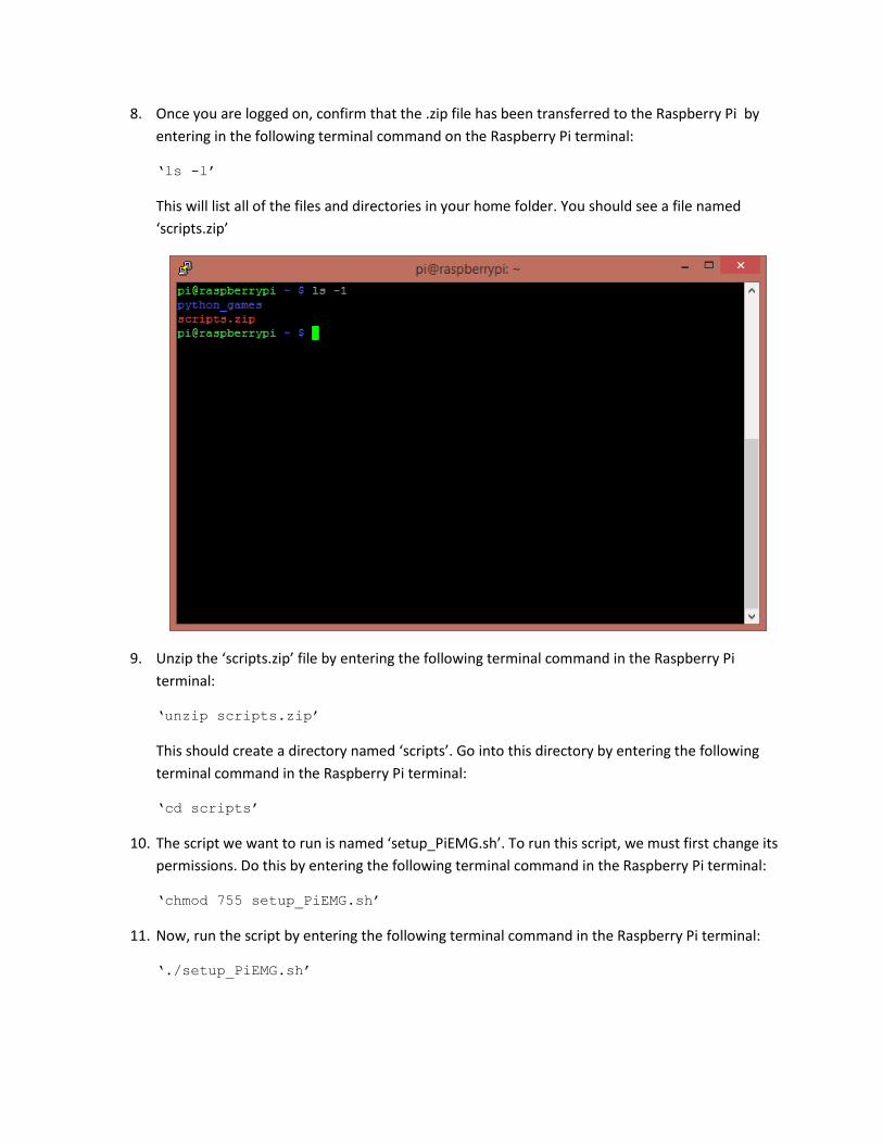
7. Log into your Raspberry Pi as described in the section titled “Connect to the Raspberry Pi with