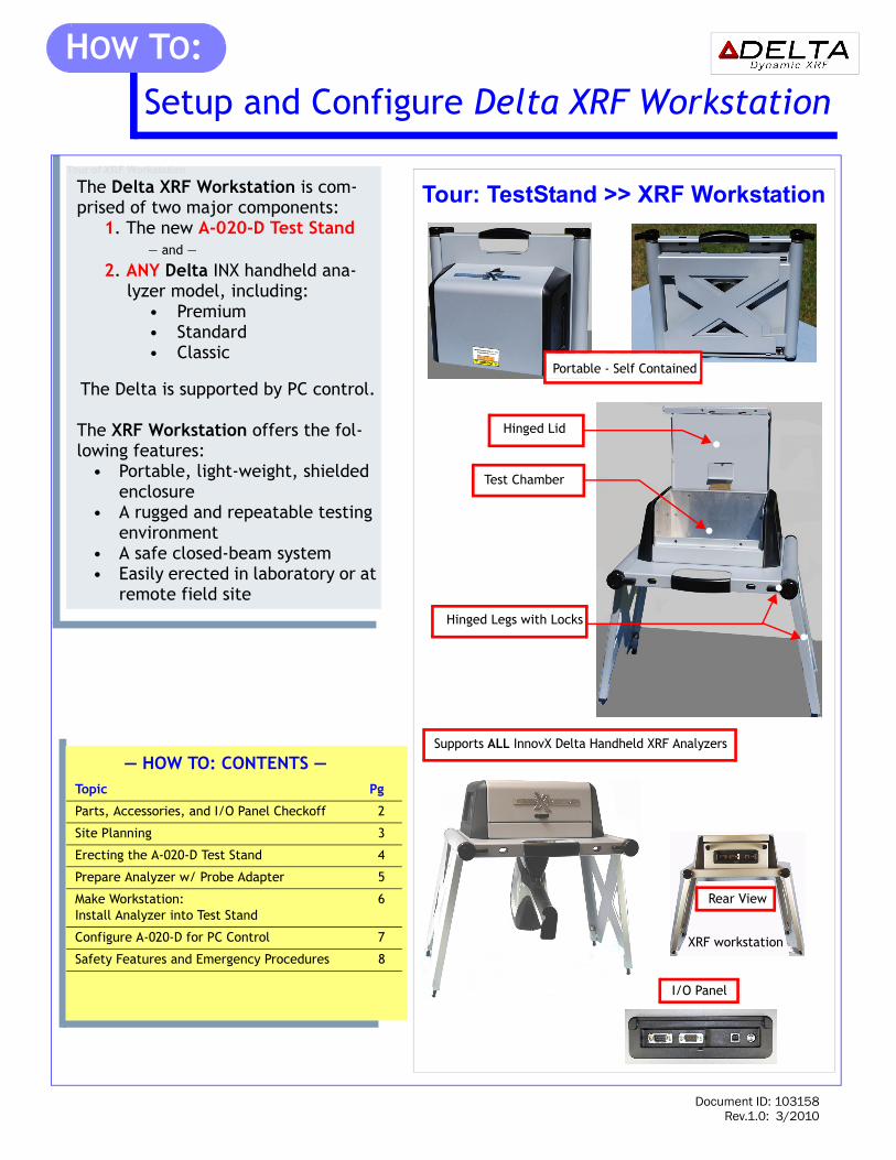
Document ID: 103158 Rev.1.0: 3/2010 Tour of XRF Workstation The Delta XRF Workstation is com- prised of two major components: 1. The new A-020-D Test Stand — and — 2. ANY Delta INX handheld ana- lyzer model, including: • Premium • Standard • Classic The Delta is supported by PC control. The XRF Workstation offers the fol- lowing features: • Portable, light-weight, shielded enclosure • A rugged and repeatable testing environment • A safe closed-beam system • Easily erected in laboratory or at remote field site Tour: TestStand >> XRF Workstation Topic Pg Parts, Accessories, and I/O Panel Checkoff 2 Site Planning 3 Erecting the A-020-D Test Stand 4 Prepare Analyzer w/ Probe Adapter 5 Make Workstation: Install Analyzer into Test Stand 6 Configure A-020-D for PC Control 7 Safety Features and Emergency Procedures 8 — HOW TO: CONTENTS — Hinged Lid Test Chamber XRF workstation Portable - Self Contained Supports ALL InnovX Delta Handheld XRF Analyzers Hinged Legs with Locks I/O Panel Rear View • • • • Setup and Configure Delta XRF Workstation HOW T O:
Transcript
Tour: TestStand >> XRF Workstation
Hinged Lid
Test Chamber
Portable - Self Contained
•
•
•
Setup and Configure Delta XRF Workstation
HOW TO:
Tour of XRF Workstation
The Delta XRF Workstation is com-prised of two major components:
1. The new A-020-D Test Stand— and —
2. ANY Delta INX handheld ana-lyzer model, including:
• Premium• Standard• Classic
The Delta is supported by PC control.
The XRF Workstation offers the fol-lowing features:
• Portable, light-weight, shielded enclosure
• A rugged and repeatable testing environment
• A safe closed-beam system• Easily erected in laboratory or at
remote field site
XRF workstation
Supports ALL InnovX Delta Handheld XRF Analyzers
Hinged Legs with Locks
I/O Panel
Rear View
•
Topic Pg
Parts, Accessories, and I/O Panel Checkoff 2
Site Planning 3
Erecting the A-020-D Test Stand 4
Prepare Analyzer w/ Probe Adapter 5
Make Workstation: Install Analyzer into Test Stand
6
Configure A-020-D for PC Control 7
Safety Features and Emergency Procedures 8
— HOW TO: CONTENTS —
Document ID: 103158Rev.1.0: 3/2010
2
Parts, Accessories, and Panel Checkoff
Parts, Accessories, and Panel Checkoff
ID Description Part NumberA Delta Probe Adapter w/ Integrated Cable Assy. No. 900486
B USB-A to MINI USB-B cable P/N 101310
C CalCheck (Standardization) Coupon P/N 100039
(Rear View)
C
XRF Workstation
I/O Panel (Cover Removed)Serial
15 Pin DSub USB 9 Pin DSub
Delta Probe AdapterA
CalCheck Coupon
w/ Integrated Cable Assembly
B USB-A to MINI USB-B cable
Do Not Use
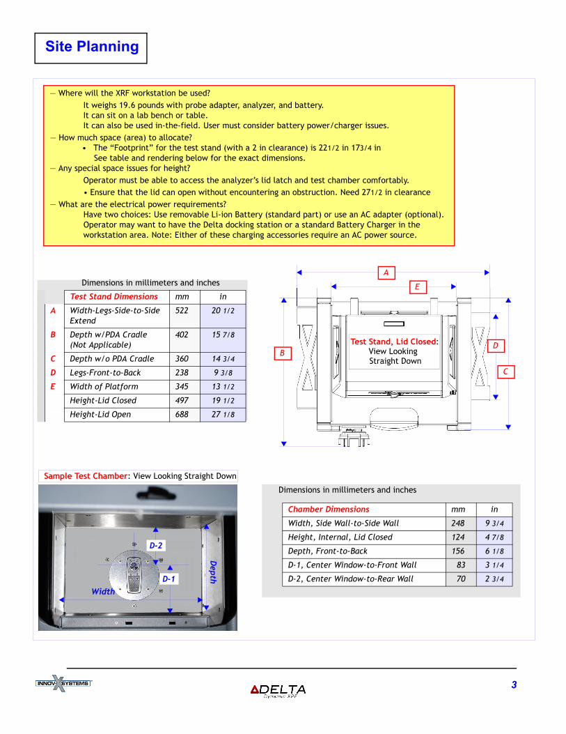
Site Planning
Site Planinning
— Where will the XRF workstation be used?It weighs 19.6 pounds with probe adapter, analyzer, and battery. It can sit on a lab bench or table.It can also be used in-the-field. User must consider battery power/charger issues.
— How much space (area) to allocate?• The “Footprint” for the test stand (with a 2 in clearance) is 221/2 in 173/4 in
See table and rendering below for the exact dimensions.— Any special space issues for height?
Operator must be able to access the analyzer’s lid latch and test chamber comfortably.• Ensure that the lid can open without encountering an obstruction. Need 271/2 in clearance
— What are the electrical power requirements? Have two choices: Use removable Li-ion Battery (standard part) or use an AC adapter (optional).Operator may want to have the Delta docking station or a standard Battery Charger in the workstation area. Note: Either of these charging accessories require an AC power source.
Depth
Width
Dimensions in millimeters and inches
Test Stand Dimensions mm in
A Width-Legs-Side-to-Side Extend
522 20 1/2
B Depth w/PDA Cradle (Not Applicable)
402 15 7/8
C Depth w/o PDA Cradle 360 14 3/4
D Legs-Front-to-Back 238 9 3/8
E Width of Platform 345 13 1/2
Height-Lid Closed 497 19 1/2
Height-Lid Open 688 27 1/8
Dimensions in millimeters and inches
Chamber Dimensions mm in
Width, Side Wall-to-Side Wall 248 9 3/4
Height, Internal, Lid Closed 124 4 7/8
Depth, Front-to-Back 156 6 1/8
D-1, Center Window-to-Front Wall 83 3 1/4
D-2, Center Window-to-Rear Wall 70 2 3/4
A
E
C
DB
D-1
D-2
Sample Test Chamber: View Looking Straight Down
Test Stand, Lid Closed:View Looking Straight Down
3
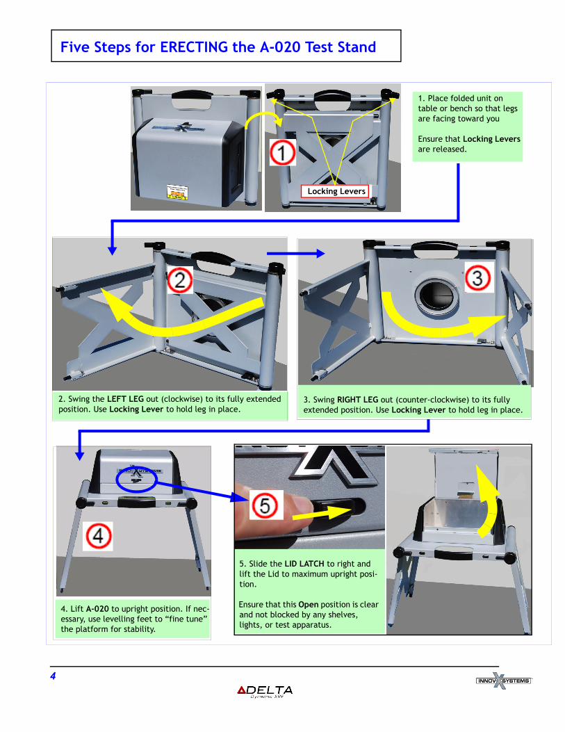
Five Steps for ERECTING the A-020 Test Stand
Five Steps for Erecting the A-20 Test Stand
5. Slide the LID LATCH to right and lift the Lid to maximum upright posi-tion.
Ensure that this Open position is clear and not blocked by any shelves, lights, or test apparatus.
3. Swing RIGHT LEG out (counter-clockwise) to its fully extended position. Use Locking Lever to hold leg in place.
1. Place folded unit on table or bench so that legs are facing toward you
Ensure that Locking Levers are released.
2. Swing the LEFT LEG out (clockwise) to its fully extended position. Use Locking Lever to hold leg in place.
4. Lift A-020 to upright position. If nec-essary, use levelling feet to “fine tune” the platform for stability.
Locking Levers
4
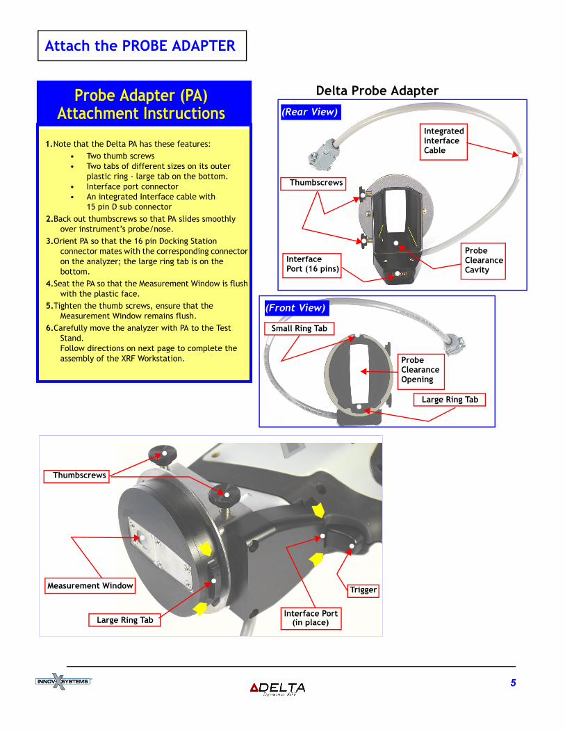
Attach the PROBE ADAPTER
Attach the Probe Adapter
1.Note that the Delta PA has these features:• Two thumb screws • Two tabs of different sizes on its outer
plastic ring - large tab on the bottom.• Interface port connector• An integrated Interface cable with
15 pin D sub connector2.Back out thumbscrews so that PA slides smoothly
over instrument’s probe/nose.3.Orient PA so that the 16 pin Docking Station
connector mates with the corresponding connector on the analyzer; the large ring tab is on the bottom.
4.Seat the PA so that the Measurement Window is flush with the plastic face.
5.Tighten the thumb screws, ensure that the Measurement Window remains flush.
6.Carefully move the analyzer with PA to the Test Stand. Follow directions on next page to complete the assembly of the XRF Workstation.
Probe Adapter (PA)Attachment Instructions
Probe
Delta Probe Adapter
CavityClearance
Thumbscrews
Probe
OpeningClearance
Interface Port
Trigger
Large Ring Tab
Thumbscrews
(in place)
Measurement Window
•
•
•
•
••
InterfacePort (16 pins)
Large Ring Tab
Small Ring Tab
IntegratedInterfaceCable
(Rear View)
(Front View)
•
•
•
•
•
•
•
5
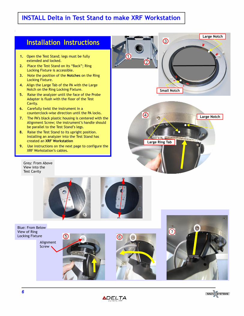
INSTALL Delta in Test Stand to make XRF Workstation
Install Handheld Instrument in Test Stand >> XRF Workstation
1. Open the Test Stand; legs must be fully extended and locked.
2. Place the Test Stand on its “Back”; Ring Locking Fixture is accessible.
3. Note the position of the Notches on the Ring Locking Fixture.
4. Align the Large Tab of the PA with the Large Notch on the Ring Locking Fixture.
5. Raise the analyzer until the face of the Probe Adapter is flush with the floor of the Test Cavity.
6. Carefully twist the instrument in a counterclock-wise direction until the PA locks.
7. The PA’s black plastic housing is centered with the Alignment Screw; the instrument’s handle should be parallel to the Test Stand’s legs.
8. Raise the Test Stand to its upright position.Installing an analyzer into the Test Stand has created an XRF Workstation
9. Use instructions on the next page to configure the XRF Workstation’s cables.
Installation Instructions
Large Ring Tab
Large Notch
Small Notch
Large Notch
Blue: From BelowView of RingLocking Fixture
Grey: From AboveView into the Test Cavity
AlignmentScrew
••
•
•
6
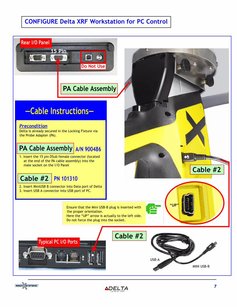
Re
CONFIGURE Delta XRF Workstation for PC Control
Configure Delta XRF Workstation for PC Control
Cable #2
conditiona is already secured in the Locking Fixture via Probe Adapter (PA).
sert the 15 pin DSub female connector (located t the end of the PA cable assembly) into the ale socket on the I/O Panel
nsert MiniUSB B connector into Data port of Deltansert USB A connector into USB port of PC.
—Cable Instructions—
15 Pin
PN 101310
A/N 900486
“UP”
MINI USB-B
USB-A•
Do Not Use
PA Cable Assembly
Cable Assembly
ble #2
Ensure that the Mini USB-B plug is inserted with the proper orientation.Here the “UP” arrow is actually to the left side.Do not force the plug into the socket.
Cable #2Typical PC I/O Ports
ar I/O Panel
PreDeltthe
1. Inam
2. I3. I
PA
Ca
7
8
Safety Features and Emergency Procedures
Hardware Safety Features
X-Ray IndicatorFour amber, high-intensity LEDs light when the X-Ray tube is enabled.The LED flashes when X-Rays are being emitted during a test.
ShieldingEntire test chamber is shielded.
Interlock SensorsLid interlocks ensure that lid is closed prior to X-Rays turning ON.If lid is lifted during an active test,the X-Ray beam turns OFF.
Proximity SensorAnalyzer shuts OFF when there is NO sample in front of measurementwindow.
Emergency Shutoff Procedures
Open LidThis shuts OFF X-Rays immediately.Test data is preserved.This is the recommended method.
On PC Press the STOP button on UI.
I/O PanelRemove PA control cable from 15-pin port.
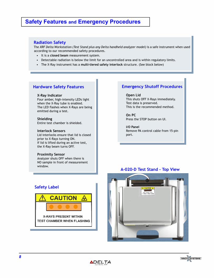
Safety Label
Radiation SafetyThe XRF Delta Workstation (Test Stand plus any Delta handheld analyzer model) is a safe instrument when used according to our recommended safety procedures.
• It is a closed beam measurement system.• Detectable radiation is below the limit for an uncontrolled area and is within regulatory limits. • The X-Ray instrument has a multi-tiered safety interlock structure. (See block below)