Severe Accident Modelling and Analysis of VVER 1000 (V-412) for Kudankulam NPP, India Abhishek K, Sil S, Gaurav K, Gokhale O.S, Mithilesh K, Saxena S.M., Mukhopadhyay D, Rammohan H.P , Biswas G Presented by Abhishek Kumar, Engg-LWR, NPCIL, India Technical Meeting on the Status and Evaluation of Severe Accident Simulation Codes for WCR, Vienna, 09-12 Oct , 2017
Transcript
Severe Accident Modelling and
Analysis of VVER 1000 (V-412)
for Kudankulam NPP, India
Abhishek K, Sil S, Gaurav K, Gokhale
O.S, Mithilesh K, Saxena S.M.,
Mukhopadhyay D, Rammohan H.P ,
Biswas G
Presented by
Abhishek Kumar, Engg-LWR, NPCIL,
India
Technical Meeting on the Status and Evaluation of Severe Accident
Simulation Codes for WCR, Vienna, 09-12 Oct , 2017
Outline
� Salient Features of KKNPP
� Safety Systems of KKNPP
� In-vessel Analysis
� Ex-vessel Core Catcher Analysis
� Identification of Modelling Issues
� Experimental Program on Degraded Core RE-flood
� Conclusion
� References
� Questions
IAEA Technical Meeting on Status of Severe Accident Simulation Codes , Vienna, 09-12 Oct, 2017 1
Salient Features of KKNPP
IAEA Technical Meeting on Status of Severe Accident Simulation Codes , Vienna, 09-12 Oct, 2017 2
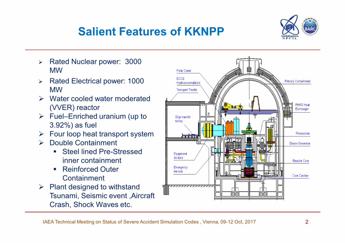
� Rated Nuclear power: 3000
MW
� Rated Electrical power: 1000
MW
� Water cooled water moderated
(VVER) reactor
� Fuel–Enriched uranium (up to
3.92%) as fuel
� Four loop heat transport system
� Double Containment
� Steel lined Pre-Stressed
inner containment
� Reinforced Outer
Containment
� Plant designed to withstand
Tsunami, Seismic event ,Aircraft
Crash, Shock Waves etc.
Salient Features of KKNPP (Continued)Reactor Coolant System
IAEA Technical Meeting on Status of Severe Accident Simulation Codes , Vienna, 09-12 Oct, 2017 3
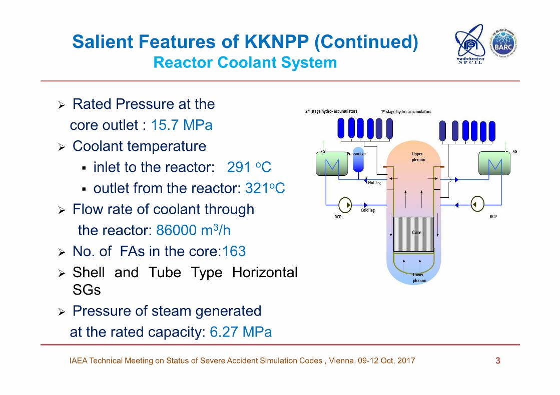
� Rated Pressure at the
core outlet : 15.7 MPa
� Coolant temperature
� inlet to the reactor: 291 оС
� outlet from the reactor: 321оС
� Flow rate of coolant through
the reactor: 86000 m3/h
� No. of FAs in the core:163
� Shell and Tube Type Horizontal
SGs
� Pressure of steam generated
at the rated capacity: 6.27 MPa
Safety Features of KKNPP
� Inherent Safety
� Negative power coefficient: Wherein any increase in reactor
power is self terminating
� Negative Void Coefficient: reactor will shut down, if there is
loss of water
� Multiple Safety Barriers
� Fuel Matrix, Fuel Cladding, RCS Circuit, Inner and outer
Containment
� Engineered features and administrative measures provided to
protect these barriers
� Active Safety Systems
� Passive Safety System
� Safety Culture
IAEA Technical Meeting on Status of Severe Accident Simulation Codes , Vienna, 09-12 Oct, 2017 4
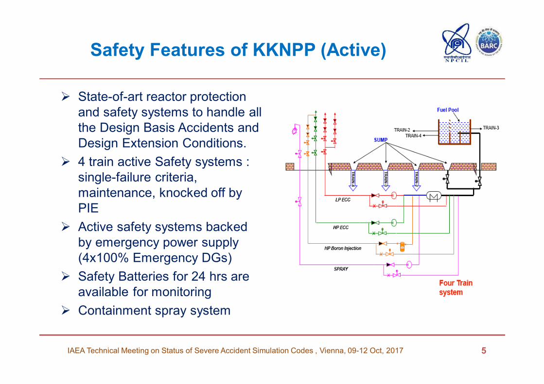
Safety Features of KKNPP (Active)
� State-of-art reactor protection
and safety systems to handle all
the Design Basis Accidents and
Design Extension Conditions.
� 4 train active Safety systems :
single-failure criteria,
maintenance, knocked off by
PIE
� Active safety systems backed
by emergency power supply
(4x100% Emergency DGs)
� Safety Batteries for 24 hrs are
available for monitoring
� Containment spray system
5IAEA Technical Meeting on Status of Severe Accident Simulation Codes , Vienna, 09-12 Oct, 2017
6IAEA Technical Meeting on Status of Severe Accident Simulation Codes , Vienna, 09-12 Oct, 2017
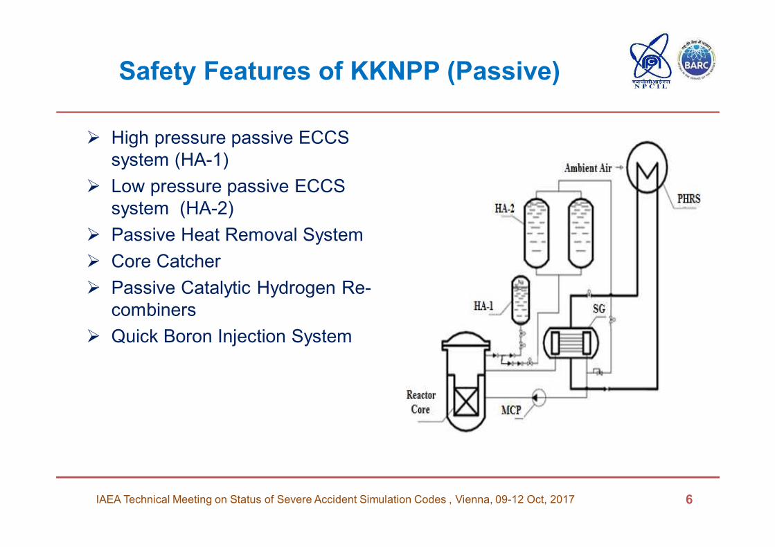
Safety Features of KKNPP (Passive)
� High pressure passive ECCS
system (HA-1)
� Low pressure passive ECCS
system (HA-2)
� Passive Heat Removal System
� Core Catcher
� Passive Catalytic Hydrogen Re-
combiners
� Quick Boron Injection System
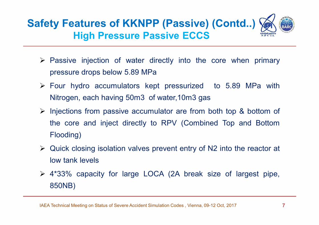
Safety Features of KKNPP (Passive) (Contd..)High Pressure Passive ECCS
� Passive injection of water directly into the core when primary
pressure drops below 5.89 MPa
� Four hydro accumulators kept pressurized to 5.89 MPa with
Nitrogen, each having 50m3 of water,10m3 gas
� Injections from passive accumulator are from both top & bottom of
the core and inject directly to RPV (Combined Top and Bottom
Flooding)
� Quick closing isolation valves prevent entry of N2 into the reactor at
low tank levels
� 4*33% capacity for large LOCA (2A break size of largest pipe,
850NB)
IAEA Technical Meeting on Status of Severe Accident Simulation Codes , Vienna, 09-12 Oct, 2017 7
Safety Features of KKNPP (Passive) (Contd..)Low Pressure Passive ECCS
IAEA Technical Meeting on Status of Severe Accident Simulation Codes , Vienna, 09-12 Oct, 2017 8
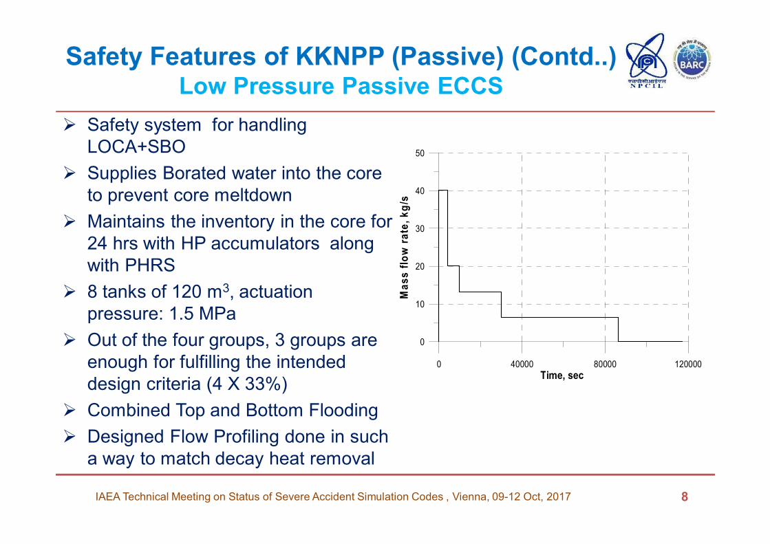
� Safety system for handling
LOCA+SBO
� Supplies Borated water into the core
to prevent core meltdown
� Maintains the inventory in the core for
24 hrs with HP accumulators along
with PHRS
� 8 tanks of 120 m3, actuation
pressure: 1.5 MPa
� Out of the four groups, 3 groups are
enough for fulfilling the intended
design criteria (4 X 33%)
� Combined Top and Bottom Flooding
� Designed Flow Profiling done in such
a way to match decay heat removal
0 40000 80000 120000
Time, sec
0
10
20
30
40
50
Ma
ss
flo
w r
ate
, k
g/s
Atmospferic air
LOSS OF POWER
Drag shaft
Atmospferic air
Drag shaft
Atmospheric
airAtmospheric
air
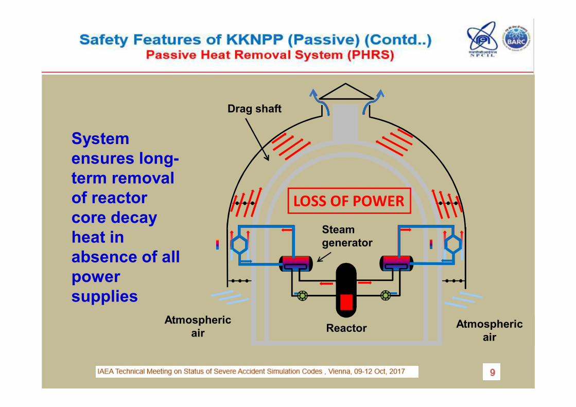
System
ensures long-
term removal
of reactor
core decay
heat in
absence of all
power
supplies
Steam
generator
Reactor
PASSIVE HEAT REMOVAL SYSTEM
Safety Features of KKNPP (Passive) (Contd..)Passive Heat Removal System (PHRS, Contd..)
� System maintains the hot shutdown condition of the reactor,
during a blackout(System operates in passive manner)
� Four trains with 3 air cooled HXs in each train
� Three trains are adequate to remove 2% decay heat
� Steam from SG is continuously passing through PHRS Hx
� Only air dampers at inlet and outlet are opened on SBO
signal, Regulatory dampers at outlet does the pressure
control
� Together with 2nd stage hydro accumulators remove decay
heat under LOCA+ SBO
IAEA Technical Meeting on Status of Severe Accident Simulation Codes , Vienna, 09-12 Oct, 2017 10
Safety Features of KKNPP (Passive)(Contd..)Core Catcher
IAEA Technical Meeting on Status of Severe Accident Simulation Codes , Vienna, 09-12 Oct, 2017 11
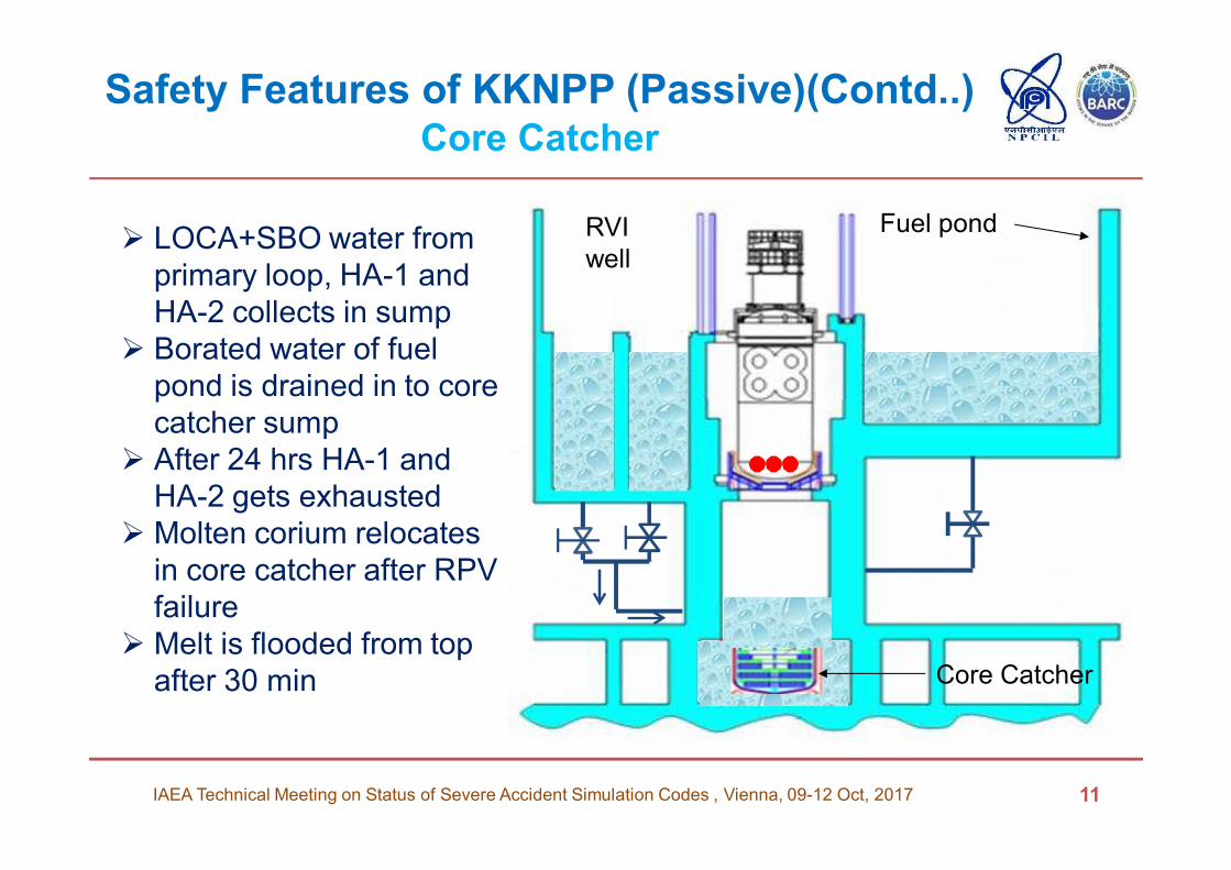
Fuel pondRVI
well
Core Catcher
� LOCA+SBO water from
primary loop, HA-1 and
HA-2 collects in sump
� Borated water of fuel
pond is drained in to core
catcher sump
� After 24 hrs HA-1 and
HA-2 gets exhausted
� Molten corium relocates
in core catcher after RPV
failure
� Melt is flooded from top
after 30 min
Analysis with ICARE Module of ASTEC
LOCA, 850mm, 2A + SBO Scenario
IAEA Technical Meeting on Status of Severe Accident Simulation Codes , Vienna, 09-12 Oct, 2017 12
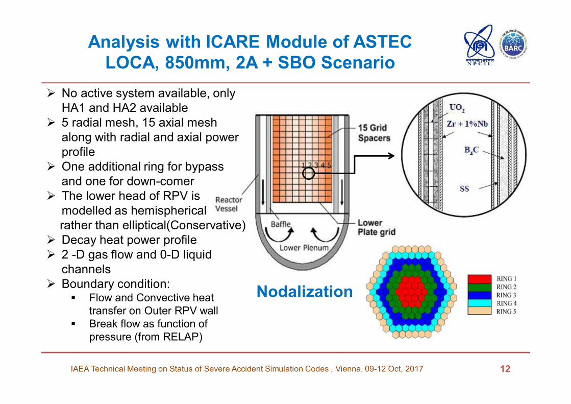
� No active system available, only
HA1 and HA2 available
� 5 radial mesh, 15 axial mesh
along with radial and axial power
profile
� One additional ring for bypass
and one for down-comer
� The lower head of RPV is
modelled as hemispherical
rather than elliptical(Conservative)
� Decay heat power profile
� 2 -D gas flow and 0-D liquid
channels
� Boundary condition: � Flow and Convective heat
transfer on Outer RPV wall
� Break flow as function of
pressure (from RELAP)
Nodalization
Analysis with ICARE Module of ASTEC
LOCA, 850mm, 2A + SBO Scenario
IAEA Technical Meeting on Status of Severe Accident Simulation Codes , Vienna, 09-12 Oct, 2017 13
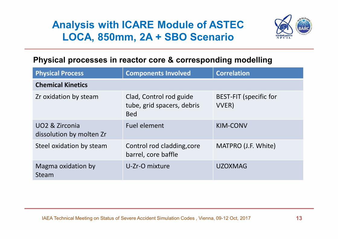
Physical Process Components Involved Correlation
Chemical Kinetics
Zr oxidation by steam Clad, Control rod guide
tube, grid spacers, debris
Bed
BEST-FIT (specific for
VVER)
UO2 & Zirconia
dissolution by molten Zr
Fuel element KIM-CONV
Steel oxidation by steam Control rod cladding,core
barrel, core baffle
MATPRO (J.F. White)
Magma oxidation by
Steam
U-Zr-O mixture UZOXMAG
Physical processes in reactor core & corresponding modelling
Analysis with ICARE Module of ASTEC
LOCA, 850mm, 2A + SBO Scenario
IAEA Technical Meeting on Status of Severe Accident Simulation Codes , Vienna, 09-12 Oct, 2017 14
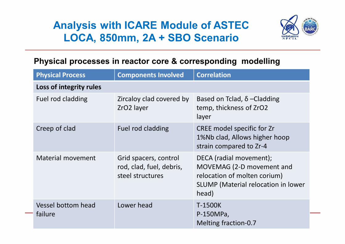
Physical Process Components Involved Correlation
Loss of integrity rules
Fuel rod cladding Zircaloy clad covered by
ZrO2 layer
Based on Tclad, δ –Cladding
temp, thickness of ZrO2
layer
Creep of clad Fuel rod cladding CREE model specific for Zr
1%Nb clad, Allows higher hoop
strain compared to Zr-4
Material movement Grid spacers, control
rod, clad, fuel, debris,
steel structures
DECA (radial movement);
MOVEMAG (2-D movement and
relocation of molten corium)
SLUMP (Material relocation in lower
head)
Vessel bottom head
failure
Lower head T-1500K
P-150MPa,
Melting fraction-0.7
Physical processes in reactor core & corresponding modelling
Analysis with ICARE Module of ASTEC
LOCA, 850mm, 2A + SBO Scenario (Results)
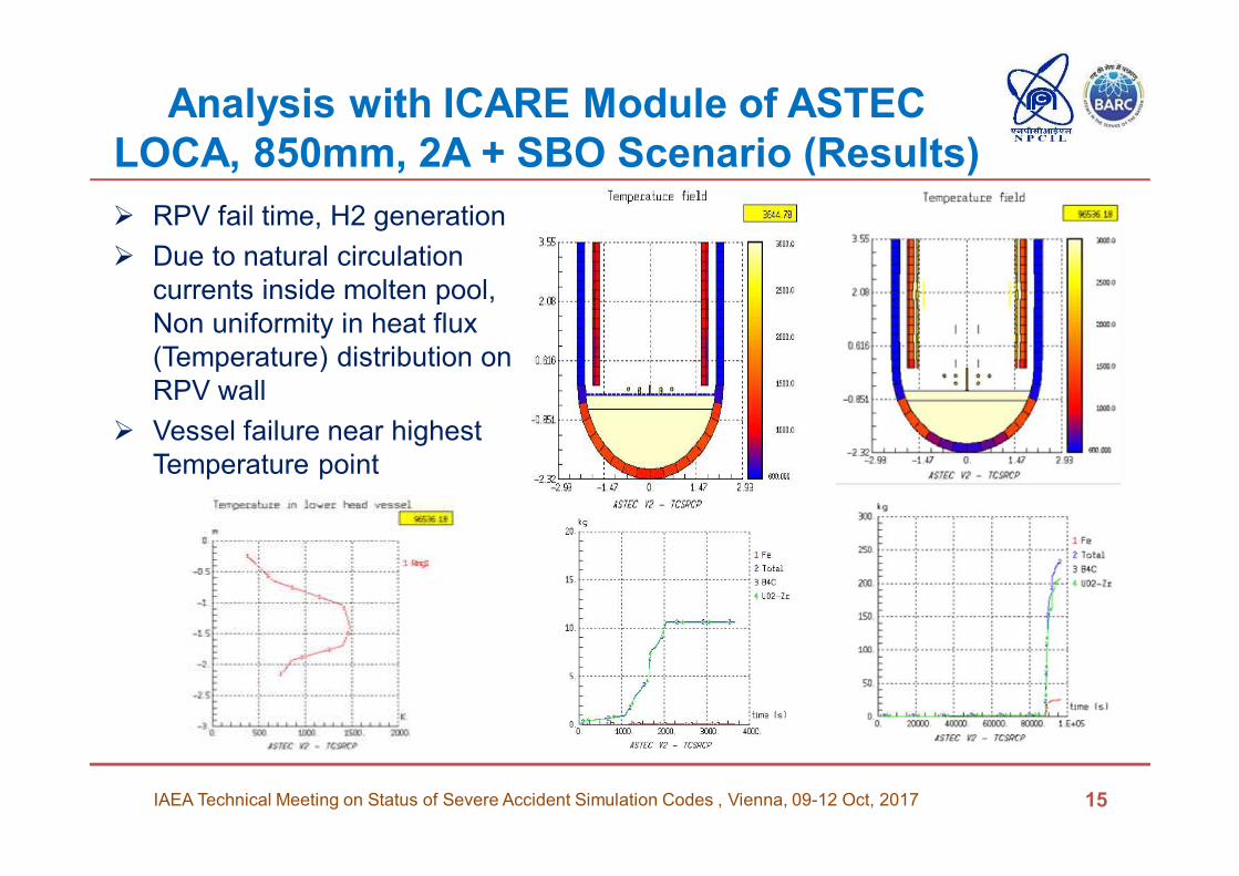
� RPV fail time, H2 generation
� Due to natural circulation
currents inside molten pool,
Non uniformity in heat flux
(Temperature) distribution on
RPV wall
� Vessel failure near highest
Temperature point
15IAEA Technical Meeting on Status of Severe Accident Simulation Codes , Vienna, 09-12 Oct, 2017
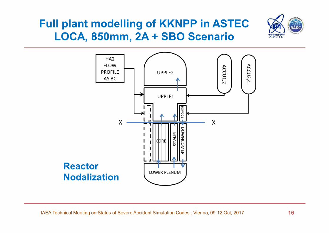
Full plant modelling of KKNPP in ASTECLOCA, 850mm, 2A + SBO Scenario
IAEA Technical Meeting on Status of Severe Accident Simulation Codes , Vienna, 09-12 Oct, 2017 16
AC
CU
1,2
AC
CU
3,4
UPPLE2
UPPLE1
CORE
LOWER PLENUM
BY
PA
SS
DO
WN
CO
ME
RD
OW
CO
1
HA2
FLOW
PROFILE
AS BC
Reactor Nodalization
X X
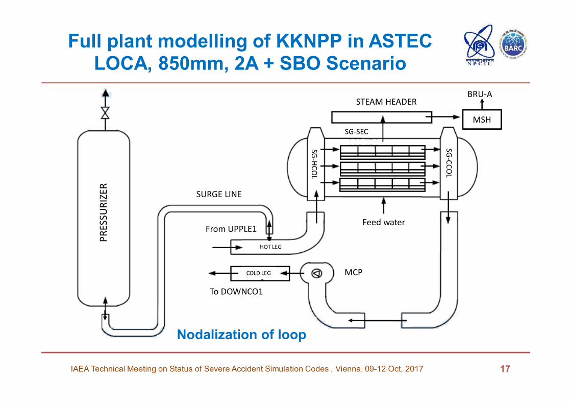
Full plant modelling of KKNPP in ASTECLOCA, 850mm, 2A + SBO Scenario
IAEA Technical Meeting on Status of Severe Accident Simulation Codes , Vienna, 09-12 Oct, 2017 17
MCP
PR
ES
SU
RIZ
ER
SURGE LINE
From UPPLE1
HOT LEG
COLD LEG
To DOWNCO1
Feed water
STEAM HEADER
MSH
BRU-A
SG
-CC
OL
SG
-HC
OL
SG-SEC
Nodalization of loop
Full plant modelling of KKNPP in ASTECLOCA, 850mm, 2A + SBO Scenario(Contd..)
� One broken loop modelled and balance three loops clubbed as one
� HA-2 flow profile as Boundary condition (Absence of dedicated model)
� Import of ICARE Reactor Core Model
� Early fuel heat-up observed in combined top and bottom
flooding of HA-2 water
� Stage -2 Accumulators water falling down in the core due to gravity head not getting simulated as there is no boundary condition available in ASTEC which allows the flow and pressure both implemented together with time
� Water was not able to penetrate till bottom of core for adequate cooling due to steam pressure
� Liquid water mass flow rate is not constant and even changes the direction at the interface between core channels and upper plenum bottom portion (Counter Current Flow Limitation)
18IAEA Technical Meeting on Status of Severe Accident Simulation Codes , Vienna, 09-12 Oct, 2017
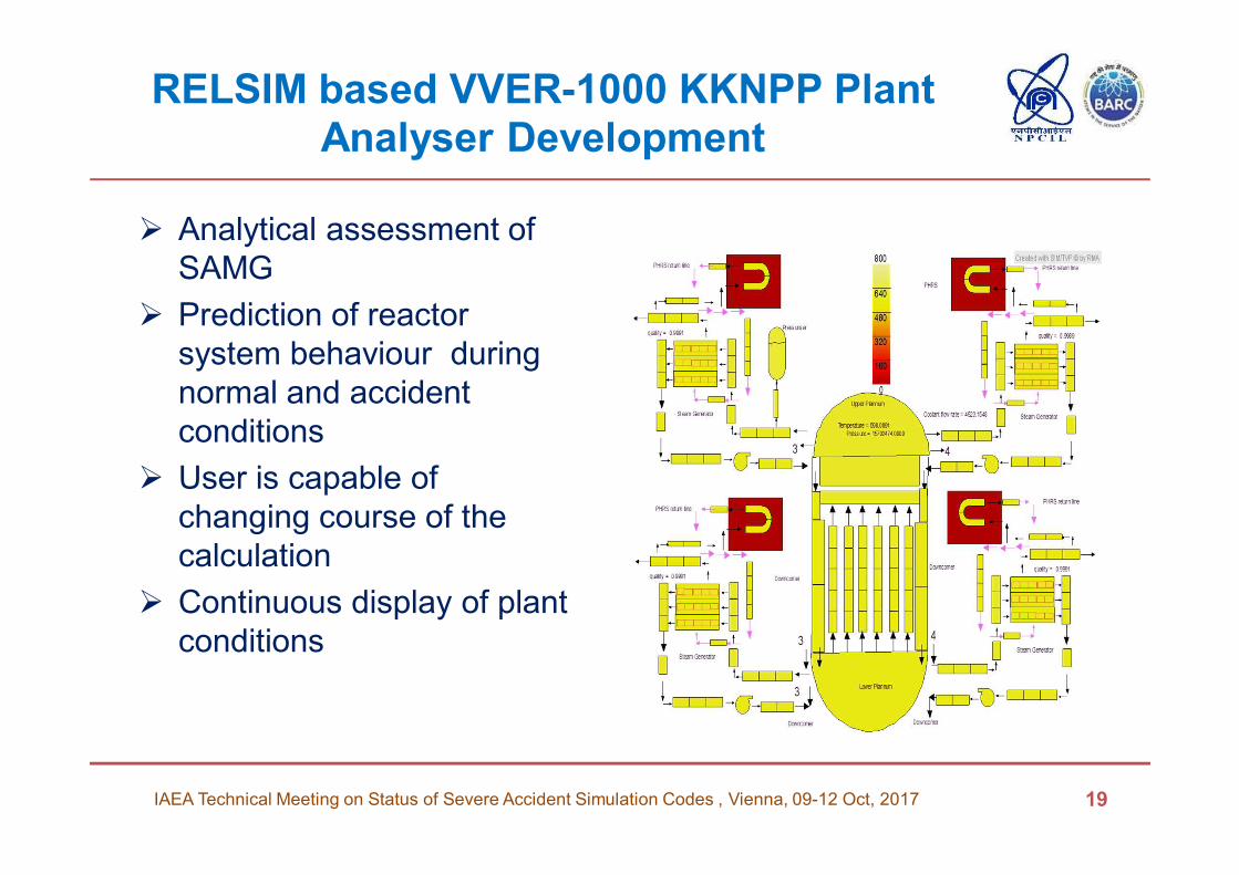
RELSIM based VVER-1000 KKNPP Plant Analyser Development
� Analytical assessment of
SAMG
� Prediction of reactor
system behaviour during
normal and accident
conditions
� User is capable of
changing course of the
calculation
� Continuous display of plant
conditions
19IAEA Technical Meeting on Status of Severe Accident Simulation Codes , Vienna, 09-12 Oct, 2017
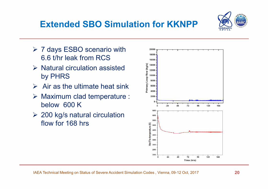
Extended SBO Simulation for KKNPP
� 7 days ESBO scenario with
6.6 t/hr leak from RCS
� Natural circulation assisted
by PHRS
� Air as the ultimate heat sink
� Maximum clad temperature :
below 600 K
� 200 kg/s natural circulation
flow for 168 hrs
20IAEA Technical Meeting on Status of Severe Accident Simulation Codes , Vienna, 09-12 Oct, 2017
Ex-vessel Core Catcher Analysis
IAEA Technical Meeting on Status of Severe Accident Simulation Codes , Vienna, 09-12 Oct, 2017 21
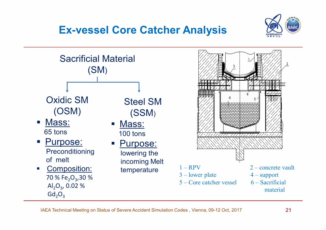
1 – RPV 2 – concrete vault
3 – lower plate 4 – support
5 – Core catcher vessel 6 – Sacrificial
material
Sacrificial Material
(SM)
Oxidic SM
(OSM)
� Mass:65 tons
� Purpose:Preconditioning
of melt
� Composition:70 % Fe2O3,30 %
Al2O3, 0.02 %
Gd2O3
Steel SM
(SSM)
� Mass:100 tons
� Purpose:lowering the
incoming Melt
temperature
Ex-vessel Core Catcher Analysis(Contd..)
IAEA Technical Meeting on Status of Severe Accident Simulation Codes , Vienna, 09-12 Oct, 2017 22
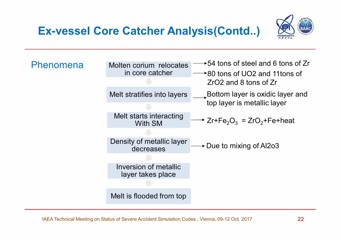
Molten corium relocates in core catcher
Melt stratifies into layers
Melt starts interacting With SM
Density of metallic layer decreases
Inversion of metallic layer takes place
Melt is flooded from top
54 tons of steel and 6 tons of Zr
80 tons of UO2 and 11tons of
ZrO2 and 8 tons of Zr
Bottom layer is oxidic layer and
top layer is metallic layer
Due to mixing of Al2o3
Zr+Fe2O3 = ZrO2+Fe+heat
Phenomena
Ex-vessel Core Catcher Analysis(Contd..)
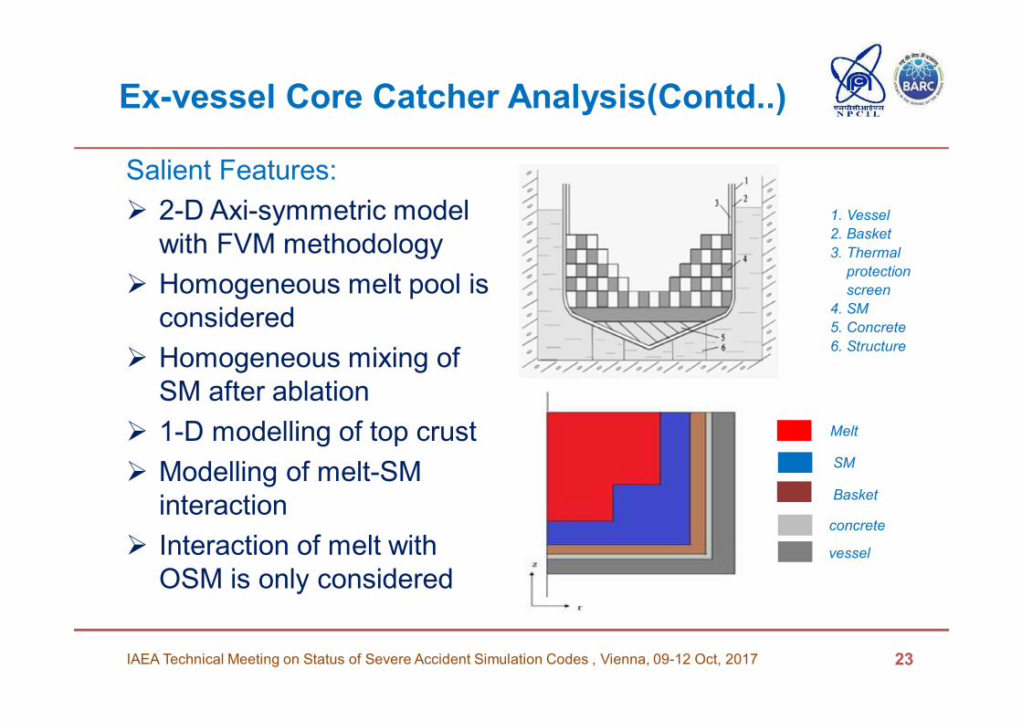
Salient Features:
� 2-D Axi-symmetric model
with FVM methodology
� Homogeneous melt pool is
considered
� Homogeneous mixing of
SM after ablation
� 1-D modelling of top crust
� Modelling of melt-SM
interaction
� Interaction of melt with
OSM is only considered
1. Vessel
2. Basket
3. Thermal
protection
screen
4. SM
5. Concrete
6. Structure
23IAEA Technical Meeting on Status of Severe Accident Simulation Codes , Vienna, 09-12 Oct, 2017
Melt
SM
Basket
concrete
vessel
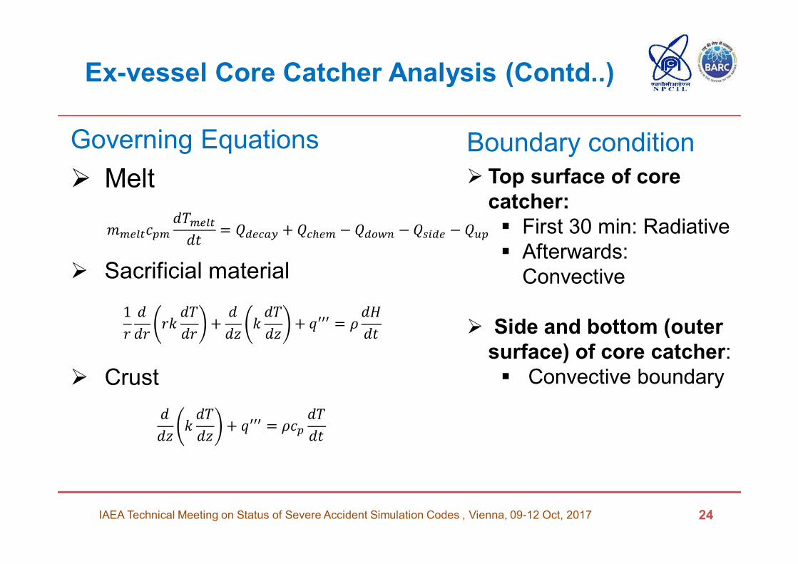
Ex-vessel Core Catcher Analysis (Contd..)
Governing Equations
� Melt
� Sacrificial material
� Crust
IAEA Technical Meeting on Status of Severe Accident Simulation Codes , Vienna, 09-12 Oct, 2017 24
�������������
�= � ���� + ����� − � ��� −��� � − ���
1
�
�
����
�
��+
�
����
��+ ���� =
�!
�
�
����
��+ ���� = ��
�
�
Boundary condition
� Top surface of core
catcher:
� First 30 min: Radiative
� Afterwards:
Convective
� Side and bottom (outer
surface) of core catcher:
� Convective boundary
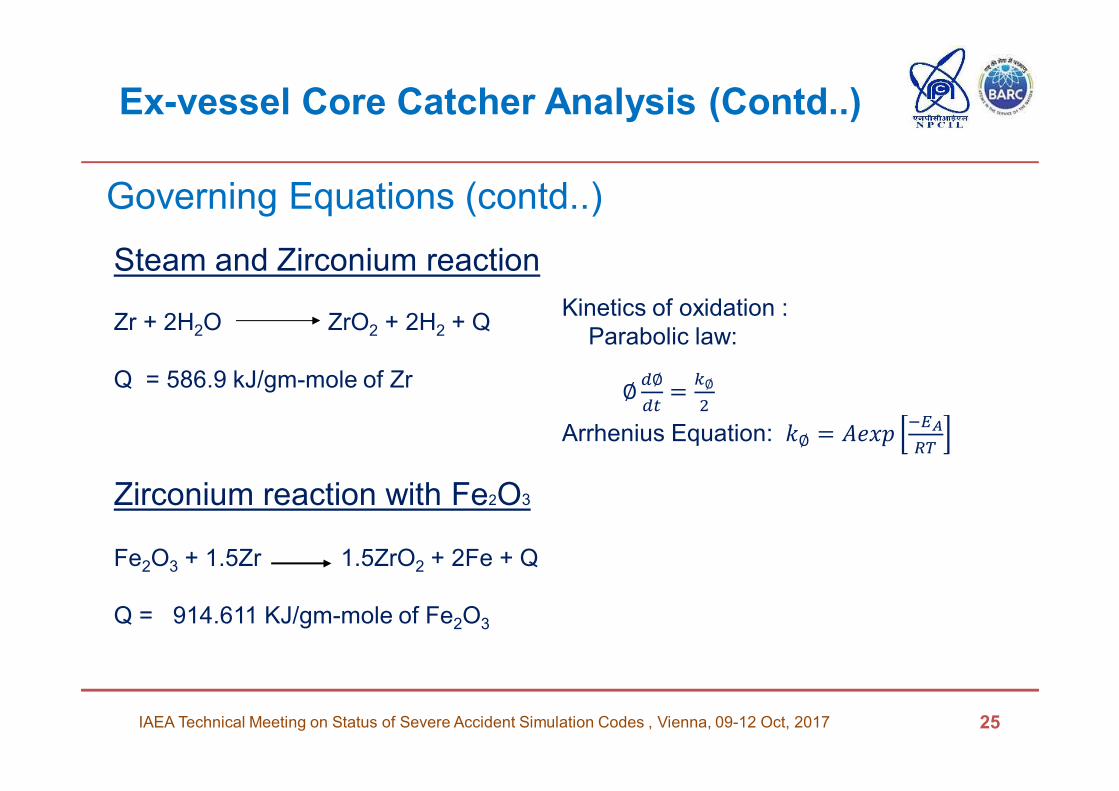
Ex-vessel Core Catcher Analysis (Contd..)
IAEA Technical Meeting on Status of Severe Accident Simulation Codes , Vienna, 09-12 Oct, 2017 25
Steam and Zirconium reaction
Zr + 2H2O ZrO2 + 2H2 + Q
Q = 586.9 kJ/gm-mole of Zr
Zirconium reaction with Fe2O3
Fe2O3 + 1.5Zr 1.5ZrO2 + 2Fe + Q
Q = 914.611 KJ/gm-mole of Fe2O3
Governing Equations (contd..)
Kinetics of oxidation :
Parabolic law:
∅ ∅
�=
$∅
%
Arrhenius Equation: �∅ = &'()*+,
-.
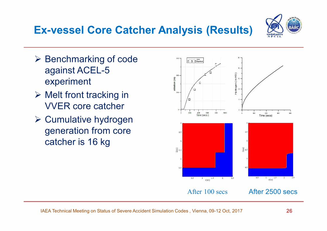
Ex-vessel Core Catcher Analysis (Results)
� Benchmarking of code
against ACEL-5
experiment
� Melt front tracking in
VVER core catcher
� Cumulative hydrogen
generation from core
catcher is 16 kg
26IAEA Technical Meeting on Status of Severe Accident Simulation Codes , Vienna, 09-12 Oct, 2017
After 100 secs After 2500 secs
Modelling Issues Related to
In-vessel Phenomena
� Difficulty in modelling of CCFL phenomena in combined top
and bottom flooding
� More bypass through break and top flooding falling water in
the core driven away by steam
� To generate data validation of ASTEC model in case of top
flooding, experimental programme with both top and bottom
flooding into VVER type fuel bundle has been taken up.
� Entire HA-2 Circuit needs to be modelled in such a way to
capture the flow profile such that gravity head driven flow
takes places till core bottom
27IAEA Technical Meeting on Status of Severe Accident Simulation Codes , Vienna, 09-12 Oct, 2017
Modelling Issues Related to Ex-vessel Phenomena
� Detailed modelling of heat transfer behavior of stratified molten corium pool or suitable modelling improvements to address this
� Due to natural convection currents inside molten pool, Non uniformity in heat flux, local hot spots can be generated, therefore modelling improvements of NC
� Body Fitted Co-ordinate System to capture the exact core catcher geometry need to be adopted (CHF Variation along the curvature)
� Scarcity of experimental measurements of oxidation kinetics for a liquid U-Zr-O mixture , therefore Suitable numerical model of molten pool oxidation considering steam ingress instead of clad oxidation model considering unlimited steam
� Relocation of Molten Corium from RPV to core catcher assumed instantaneous whereas it is over a period,
� Numerical model for mixing of SM into molten pool considering mass diffusivity
� Physical properties of Corium (Solidus and Liquidus Temperatures, effective viscosity etc. especially at High temp
28IAEA Technical Meeting on Status of Severe Accident Simulation Codes , Vienna, 09-12 Oct, 2017
Experimental program on Re-flood of
degraded Core
IAEA Technical Meeting on Status of Severe Accident Simulation Codes , Vienna, 09-12 Oct, 2017 29
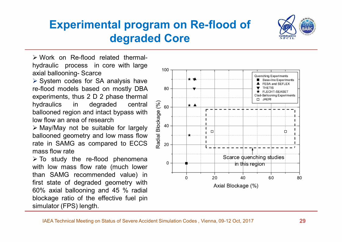
� Work on Re-flood related thermal-
hydraulic process in core with large
axial ballooning- Scarce
� System codes for SA analysis have
re-flood models based on mostly DBA
experiments, thus 2 D 2 phase thermal
hydraulics in degraded central
ballooned region and intact bypass with
low flow an area of research
� May/May not be suitable for largely
ballooned geometry and low mass flow
rate in SAMG as compared to ECCS
mass flow rate
� To study the re-flood phenomena
with low mass flow rate (much lower
than SAMG recommended value) in
first state of degraded geometry with
60% axial ballooning and 45 % radial
blockage ratio of the effective fuel pin
simulator (FPS) length.
Experimental program on Re-floodDegraded Core Re-flood Experiment Test (DCRET) Facility at
Bhabha Atomic Research Centre, India
IAEA Technical Meeting on Status of Severe Accident Simulation Codes , Vienna, 09-12 Oct, 2017 30
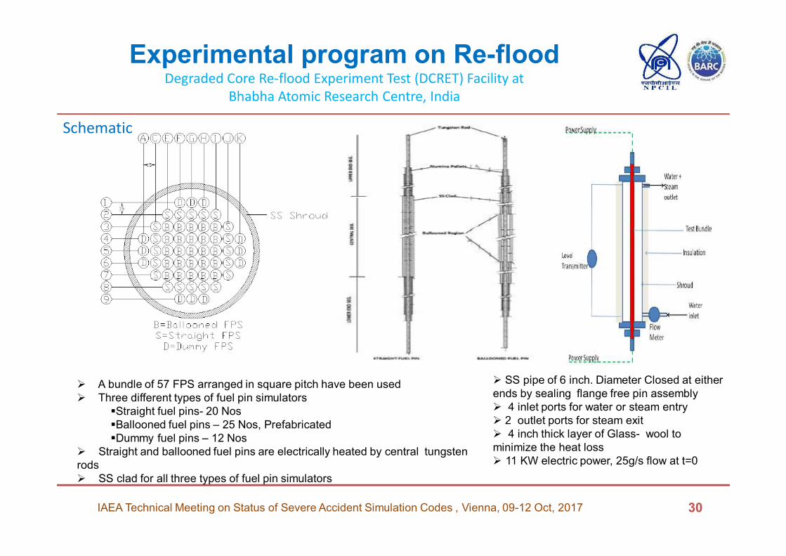
� A bundle of 57 FPS arranged in square pitch have been used
� Three different types of fuel pin simulators
�Straight fuel pins- 20 Nos
�Ballooned fuel pins – 25 Nos, Prefabricated
�Dummy fuel pins – 12 Nos
� Straight and ballooned fuel pins are electrically heated by central tungsten
rods
� SS clad for all three types of fuel pin simulators
Schematic
� SS pipe of 6 inch. Diameter Closed at either
ends by sealing flange free pin assembly
� 4 inlet ports for water or steam entry
� 2 outlet ports for steam exit
� 4 inch thick layer of Glass- wool to
minimize the heat loss
� 11 KW electric power, 25g/s flow at t=0
Modelling details and results
IAEA Technical Meeting on Status of Severe Accident Simulation Codes , Vienna, 09-12 Oct, 2017 31
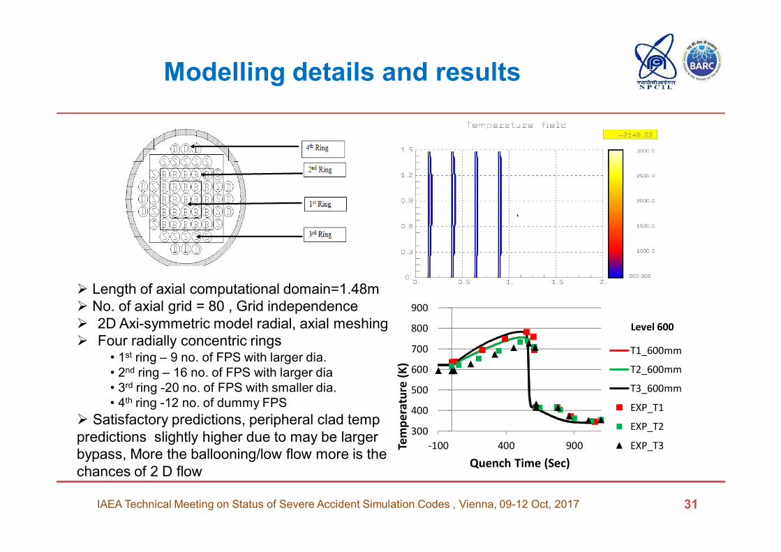
� Length of axial computational domain=1.48m
� No. of axial grid = 80 , Grid independence
� 2D Axi-symmetric model radial, axial meshing
� Four radially concentric rings• 1st ring – 9 no. of FPS with larger dia.
• 2nd ring – 16 no. of FPS with larger dia
• 3rd ring -20 no. of FPS with smaller dia.
• 4th ring -12 no. of dummy FPS
� Satisfactory predictions, peripheral clad temp
predictions slightly higher due to may be larger
bypass, More the ballooning/low flow more is the
chances of 2 D flow
300
400
500
600
700
800
900
-100 400 900Tem
pe
ratu
re (
K)
Quench Time (Sec)
Level 600
T1_600mm
T2_600mm
T3_600mm
EXP_T1
EXP_T2
EXP_T3
Experimental program for VVER Triangular
pitch fuel Simulator
� Efforts are on to have VVER scaled down triangular pitch
bundle configuration fuel pin simulator for
� Normal Bundle Configuration
� Pre-fabricated ballooned condition for low temperature
(upto 1000 deg C) and high temperature (upto 2200 deg.
C) with bottom and top re-flood conditions with different
flow rates
� To understand complex thermal-hydraulics and quenching
pattern with combined top and bottom flooding
� The minimum flow rates may be identified which would be
able to quench the bundle through both and individual
mode of flooding.
IAEA Technical Meeting on Status of Severe Accident Simulation Codes , Vienna, 09-12 Oct, 2017 32
Conclusion
� Core is adequately cooled even for 7 days in case of Extended SBO
� In case of LOCA+ESBO Core Heat up till 24 hrs is avoided as core is
adequately cooled
� By introducing Core catcher the Hydrogen generation is adequately
suppressed thereby lowering load on Containment
� Core can be confined in Core Catcher
� Sufficient understanding developed by analytical and experimental
works for severe accident and modelling with state of art
computational tools as available internationally
� Modelling issues identified and dedicated efforts are ongoing to
address the issues
� Experimental programs are on-going to understand the complex re-
flood phenomena for bottom and top re-flooding modes
33IAEA Technical Meeting on Status of Severe Accident Simulation Codes , Vienna, 09-12 Oct, 2017
References
1. A. D. Vasiliev, “Modeling of Thermal Hydraulics Aspects of Combined Top and Bottom Water
Reflood Experiment PARAMETER-SF2 Using SOCRAT 2.1 Code”, Proceedings of International
Mechanical Engineering Congress and Exposition, Boston, Massachusetts, USA, October 31–
November 6, pp. 1915-1922 (200
2. Yu Zvonarev, A. Volchek, V. Kobzar, P. Chatelard, J.P. Van Dorsselaere, “ASTEC and
ICARE/CATHARE modelling improvement for VVERs”, Nuclear Engineering and Design, Volume