92
Sewage Engineering Planning Guide 2005
SewageEngineering
Planning Guide
2005

H E A D E R S
2 Subject to modifications 03/2005 WILO AG
EN 12056DIN 1986-100Local regulationsNational regulations
DIN EN 12050EN 12056
DIN EN 12050EN 12056DIN 1986-100
DIN EN 12050
EN 12056DIN 1986-100
Local regulationsNational regulations
EN 752DIN 1986-100
EN 1610, ATV-DVWK
DIN EN 12050EN 12056
EN 752
DIN 1986-100
Determining the discharge criteria
Determining the installation criterion
Interior installation
Sump regulation
Accessories Accessories
Doublesystem
Individualsystem
Doublesystem
Individualsystem
Doublesystem
Individualsystem
Doublesystem
Individualsystem
Doublesystem
Individualsystem
Containing faecal matter
Opensystem
Closedsystem
Faecal-free
Exterior installation
Containing faecal matter Faecal-free
Rough calculation procedure for sewage systems underconsideration to normative guidelines

C O N T E N T S
Wilo Sewage Engineering Planning Guide 2005 3
Basics
Validity of standards in building drainage 5
General basic concepts 6
Basic hydraulic concepts and pipelines 17
Basic electrical concepts and their influences 24
Installation and calculation examples
General instructions for calculation 31
Planning instructions for interior installation 32
Planning instructions for exterior installation – sump pump stations 40
Additional planning instructions
Peripherals 63
Selecting switching devices for submersible pumps 64
Sump design 66
Fault diagnostics 67
Annex
Checklists for installation, operation and maintenance 69
Tables and diagrams for calculation examples 76
Conversion tables of dimensions 85
Abbreviations 86
Standards used 86
Index 88
Imprint 91

4

Wilo Sewage Engineering Planning Guide 2005 5
Because of the changed structures in Europe, thestandards have now been revised (for all EUmember states) on a cross-national basis. Coun-try-specific standards have been revised intointernationally valid EN standards, each of whichcontains slight adaptations to the typical situa-tion of each country in its national foreword.
Country-specific, supplementary standards mayalso be in force, as long as these do not contra-dict or constrain the valid EN standards (forexample, DIN 1986-100 for Germany). For Germany, this does not result in any substantialchanges in the way of thinking, as one of thehighest standards has since been used as thebasis in that country.
In addition, the ATV-DVWK (German WastewaterAssociation) applies in Germany beginning at theproperty line outside private property. Beginningin 2005, this will be known as the DWA.
The standards are an official guideline withregard to scope of validity, applications, installa-tions, safety precautions and maintenance, andhave the status of recognised rules of technol-ogy. They are not laws with which compliance ismandatory. However, these standards are appliedwhen difficulties are encountered in judgingliability cases. For example, non-compliance canrender insurance protection null and void, andthe person who has carried out the work can beheld liable.
BasicsValidity of standards in building drainage
EN 12056
DIN EN 12050
DIN 1986-100
DIN EN 12050
DIN 1986-100
ATV-DVWK
beginning in 2005, DWA "GermanAssociation for Water, Sewageand Waste"
EN 752
Building boundary Property boundary

B A S I C S
6 Subject to modifications 03/2005 WILO AG
Runoff coefficient C
Specifies the value or the factor for precipitationrelative to the composition of the surface, suchas the pavement, on which the precipitation fallsand from which it is drained.
Drainage coefficient K
Specifies the value for the frequency with whichdrainage sources are used. Accordingly, a nondi-mensional factor is assigned to every drainagesource. (Also refer to Table 1 of the Annex, "Valuesfor characteristic drainage K")
Abrasion
Material loss due to frictional contact of solidparticles in the sewage fluid and the correspon-ding surfaces of the installation (such as pumpcomponents and pipelines). The most frequentcause of abrasion is sand.
Sewage generation
The quantity of sewage generated depends onthe building type, times of use and the habits ofthe occupants. Precipitation water is added to thesewage generation. (Also refer to "Combinedsystem" on page 12, "Separate system" on page 14)
Sewage types
Sewage is defined as any type of contaminatedwater generated in the residential or commercialarea. This includes rainwater, water that becomesdirty through use, commercially used water etc.
Domestic sewageDomestic (household) sewage is a mixture ofdrinking water and organic and inorganic materi-als in both solid and dissolved form. Experiencehas shown that the materials primarily encoun-tered in household sewage are human faecalmatter, hair, food waste, cleaning agents anddetergents, as well as various types of chemicals,papers, rags and sand (for example in combinedsystems through rainwater erosion). However,experience has also shown that all kinds of wasteare introduced as a result of ignorance or non-compliance, and must then be discharged throughthe drainage source.
However, the following materials should notreach the domestic sewage stream, as otherwisedamage to the system and the adjacent installa-tions is probable:
• Large waste items, such as domestic waste• Solid particles such as sand, ashes, shards etc.• Domestic, organic solid wastes such as veg-
etable waste, peels, bones etc.• Cloth scraps, feminine hygiene products etc.• Hazardous materials such as chemically aggres-
sive solvents
RainwaterUnused precipitation water contaminated only byair pollutants, impurities from dirt on the runoffsurface or other ecological circumstances. Thedegree of contamination depends primarily ongeography, proximity to cities (air and surfacepollution) and frequency of rainfall. Impuritiesfrequently contain oil, salt, sand, or grease.
Precipitation values can differ based on condi-tions that vary greatly according to climate. The precipitation values are distinguishedaccording to frequency and intensity of rainfall.A table of these reference values is provided inDIN 1986-100 (also refer to Table 4 of the Annex,"Rainfall intensities in Germany").
Because climactic conditions change, consult the German Weather Service or local institutionsfor more accurate information. A value of 300 l/(s x ha) can be used for rough calculationswhen flooding must be avoided under all circum-stances.
General basic concepts
DIN1986-100
ATV-DVWKA118
B A S I C S
Wilo Sewage Engineering Planning Guide 2005 7
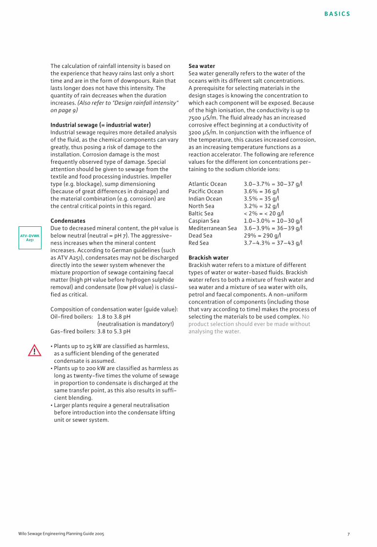
The calculation of rainfall intensity is based onthe experience that heavy rains last only a shorttime and are in the form of downpours. Rain thatlasts longer does not have this intensity. Thequantity of rain decreases when the durationincreases. (Also refer to "Design rainfall intensity"on page 9)
Industrial sewage (= industrial water)Industrial sewage requires more detailed analysisof the fluid, as the chemical components can varygreatly, thus posing a risk of damage to theinstallation. Corrosion damage is the mostfrequently observed type of damage. Specialattention should be given to sewage from thetextile and food processing industries. Impellertype (e.g. blockage)‚ sump dimensioning(because of great differences in drainage) andthe material combination (e.g. corrosion) arethe central critical points in this regard.
CondensatesDue to decreased mineral content, the pH value isbelow neutral (neutral = pH 7). The aggressive-ness increases when the mineral contentincreases. According to German guidelines (suchas ATV A251), condensates may not be dischargeddirectly into the sewer system whenever themixture proportion of sewage containing faecalmatter (high pH value before hydrogen sulphideremoval) and condensate (low pH value) is classi-fied as critical.
Composition of condensation water (guide value):Oil-fired boilers: 1.8 to 3.8 pH
(neutralisation is mandatory!)Gas-fired boilers: 3.8 to 5.3 pH
• Plants up to 25 kW are classified as harmless, as a sufficient blending of the generatedcondensate is assumed.
• Plants up to 200 kW are classified as harmless aslong as twenty-five times the volume of sewagein proportion to condensate is discharged at thesame transfer point, as this also results in suffi-cient blending.
• Larger plants require a general neutralisationbefore introduction into the condensate liftingunit or sewer system.
Sea waterSea water generally refers to the water of theoceans with its different salt concentrations.A prerequisite for selecting materials in thedesign stages is knowing the concentration towhich each component will be exposed. Becauseof the high ionisation, the conductivity is up to7500 µS/m. The fluid already has an increasedcorrosive effect beginning at a conductivity of3200 µS/m. In conjunction with the influence ofthe temperature, this causes increased corrosion,as an increasing temperature functions as areaction accelerator. The following are referencevalues for the different ion concentrations per-taining to the sodium chloride ions:
Atlantic Ocean 3.0–3.7% = 30–37 g/lPacific Ocean 3.6% = 36 g/lIndian Ocean 3.5% = 35 g/lNorth Sea 3.2% = 32 g/lBaltic Sea < 2% = < 20 g/lCaspian Sea 1.0–3.0% = 10–30 g/lMediterranean Sea 3.6–3.9% = 36–39 g/lDead Sea 29% = 290 g/lRed Sea 3.7–4.3% = 37–43 g/l
Brackish waterBrackish water refers to a mixture of differenttypes of water or water-based fluids. Brackishwater refers to both a mixture of fresh water andsea water and a mixture of sea water with oils,petrol and faecal components. A non-uniformconcentration of components (including thosethat vary according to time) makes the process ofselecting the materials to be used complex. Noproduct selection should ever be made withoutanalysing the water.
ATV-DVWKA251

B A S I C S
8 Subject to modifications 03/2005 WILO AG
Limited-use plants
These mini lifting plants (such as the Wilo-Drain-Lift KH 32) are installed immediately behind atoilet located below the backflow level (also referto page 12). However, the use of these systems issubject to certain restrictions. For example, theremust be an alternative toilet above the backflowlevel for use in case the mini lifting plant fails. Inaddition, the inlets are restricted to a maximum ofone hand wash basin, one shower and one bidet(urinal), all of which must be located in the sameroom. Bathtubs, washing machines or dishwash-ers are not permitted. Installation above thebackflow level is permitted only in special cases,such as renovations.
Drain connection value DU
Indicates the average drainage quantity of adrainage source. The values are listed in l/s. (Alsorefer to Table 2 of the Annex, "Drain connectionvalues (DU) for sanitary fixtures")
Installation types
Stationary wet sump installation
In recent years, prefabricated pump sumps madeof concrete and plastic have come into wide-spread use, as they can be installed quickly andeasily, lowering installation costs. The advan-tages of pumps in wet sump installations lie incost and space considerations, as a separatepump chamber is not required for pump installa-tion as is the case in dry sump installation. On theother hand, when maintenance is required, theeffort for checking and repairing the pump isincreased due to the need to lift the pump.
For these complete solutions, which are offeredby most pump manufacturers (such as the Wilo-Drain WS), the sumps are already adapted to anoptimum geometry that will guarantee durabilityand a long service life. In addition, all componentsare matched to each other, and all accessories areincluded in the scope of delivery.
Stationary vertical dry sump installation
Stationary horizontal dry sump installation
In the past, many pumping stations were equipped with glanded pumps. However, thishas changed for the reasons listed below, withthe result that more pump stations are beinginstalled with dry submersible pumps, regardlessof whether they are installed horizontally orvertically.
EN 12056-1and
DIN EN12050-3

B A S I C S
Wilo Sewage Engineering Planning Guide 2005 9
The reasons > advantages:• Flood-proof > Operational reliability• No stuffing box seals, instead low-mainte-
nance SiC/SiC mechanical seals > Cost reduction
• No couplings or V-belts, meaning fewer wearparts and less maintenance effort > Cost reduction
• No sealing water connections or separategrease lubrication > Cost reduction
• Integrated forced-flow casing cooling > Noise reduction
• Easy access for maintenance and repair > Cost reduction
Portable wet sump installation
In portable wet sump installation, the units areequipped with a pump base. The delivery con-nection is either flexible (high-pressure hose) orrigid (via pipeline). For draining pits or tanks, thepumps are temporarily lowered into the fluid.
It should be ensured that the pumps are posi-tioned on the foundation in a way that is solidand torsion-proof and thus cannot begin to driftor twist. In addition, the units may not be oper-ated suspended from a chain or the cable.Portable set-ups are temporary installations! Ifthey are used as a long-term solution, reducedservice life caused by increased vibrations andcorresponding negative effects on the pumpshould be taken into account.
Buoyancy protection
Buoyancy protection is a means of anchoring aunit/pump to the floor (or to the undergroundsump) to prevent it from buoying upwards in caseof flooding of the area (or increased groundwaterlevel), as this could cause damage to connec-tions/pipelines which could, in turn, cause fluidleaks. The buoyancy protection is located directlyon tanks, is retrofitted, or is integrally cast.
Ventilation
Air vents are permitted in compliance with prEN 12380 for gravity drainage systems. Thedimensioning must be carried out in conjunctionwith the connection pipe or wastewater down-pipe. Ventilation of lifting plants must be inaccordance with EN 12056-1.
Design rainfall intensity
The value is defined by local authorities. Refer-ence values are provided in DIN 1986-100 andATV-DVWK A 118, Tab. 3. A minimum value of r5(0.5) is to be assumed. If no value is specified forr, 200 l/ (s x ha) can generally be assumed forsurfaces with limited infiltration. If flooding mustbe generally prevented, experience has shownthat a value of 300 l/(s x ha) can be used forcalculation. However, the specifications of theauthorities must always be followed. (Also referto "Sewage types – Rainwater" on page 6)
prEN 12380EN 12056-1
DIN 1985-100and
ATV-DVWKA118
B A S I C S
10 Subject to modifications 03/2005 WILO AG
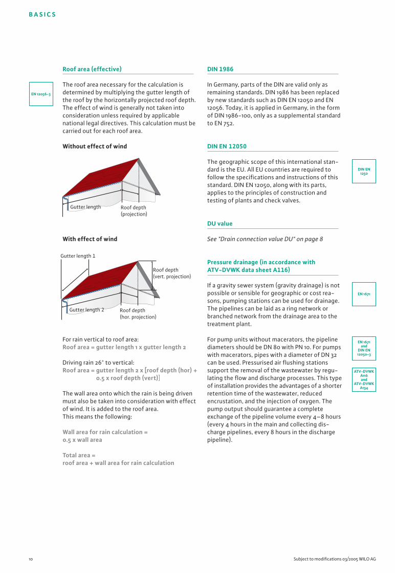
Roof area (effective)
The roof area necessary for the calculation isdetermined by multiplying the gutter length ofthe roof by the horizontally projected roof depth.The effect of wind is generally not taken intoconsideration unless required by applicablenational legal directives. This calculation must becarried out for each roof area.
Without effect of wind
With effect of wind
For rain vertical to roof area:Roof area = gutter length 1 x gutter length 2
Driving rain 26° to vertical:Roof area = gutter length 2 x [roof depth (hor) +
0.5 x roof depth (vert)]
The wall area onto which the rain is being drivenmust also be taken into consideration with effectof wind. It is added to the roof area. This means the following:
Wall area for rain calculation = 0.5 x wall area
Total area = roof area + wall area for rain calculation
DIN 1986
In Germany, parts of the DIN are valid only asremaining standards. DIN 1986 has been replacedby new standards such as DIN EN 12050 and EN12056. Today, it is applied in Germany, in the formof DIN 1986-100, only as a supplemental standardto EN 752.
DIN EN 12050
The geographic scope of this international stan-dard is the EU. All EU countries are required tofollow the specifications and instructions of thisstandard. DIN EN 12050, along with its parts,applies to the principles of construction andtesting of plants and check valves.
DU value
See "Drain connection value DU" on page 8
Pressure drainage (in accordance with ATV-DVWK data sheet A116)
If a gravity sewer system (gravity drainage) is notpossible or sensible for geographic or cost rea-sons, pumping stations can be used for drainage.The pipelines can be laid as a ring network orbranched network from the drainage area to thetreatment plant.
For pump units without macerators, the pipelinediameters should be DN 80 with PN 10. For pumpswith macerators, pipes with a diameter of DN 32can be used. Pressurised air flushing stationssupport the removal of the wastewater by regu-lating the flow and discharge processes. This typeof installation provides the advantages of a shorterretention time of the wastewater, reducedencrustation, and the injection of oxygen. Thepump output should guarantee a completeexchange of the pipeline volume every 4–8 hours(every 4 hours in the main and collecting dis-charge pipelines, every 8 hours in the dischargepipeline).
EN 12056-3
Roof depth (hor. projection)
Roof depth (vert. projection)
Gutter length 2
Gutter length 1
Roof depth (projection)
Gutter length
EN 1671
DIN EN1250
EN 1671and
DIN EN12050-3
ATV-DVWKA116and
ATV-DVWKA134

B A S I C S
Wilo Sewage Engineering Planning Guide 2005 11
Other good reasons to use pressure drainagesystems include:• Insufficient terrain gradient• High groundwater level• Low population density• Difficult subsoil• Intermittent sewage generation
(campgrounds, excursion restaurants etc.)• Environmental concerns
Fluid
Correct design and selection of a pump requireexact knowledge of the pumped fluid. When apump is used, this need not refer exclusively tosewage. The properties of sewage pumps meanthat they can pump a variety of other fluids. For amore precise definition of sewage, see "Sewagetypes" (page 6), "Materials properties" (page 16),"Free ball passage" (page 19), "Impeller types"(page 21).
Noise development (also refer to "Sound insulation")
When planning a building, the noise behaviour ofan installation must be taken into consideration,as this creates a stress factor over the long term.The individual acceptable stress loads are definedin accordance with EN 12056-1 in the correspon-ding national and regional directives. In Germany,DIN 4109 is applied here. Thus, the maximum per-mitted noise level in the adjacent room is 30 dB[A].
Corrosion
The term "corrosion" refers to the reaction of amaterial with its gaseous or liquid environment.This reaction causes a structural change of thesurface of the material and thus an impairment ofits original function. The strength of the corro-sion depends on the combination of the materialwith the aggressiveness of the fluid. Experiencehas shown that plastics and ceramic materials arethe most resistant.
When metallic materials are used, weak points aredamage to the surface or welds and connectingseams.
ChloridesChloride ions are aggressive towards metallicmaterials, which results in pitting of the metallicmaterial beginning at a concentration of
~150 mg/l.
Evaluation of installation types and drainage techniques
Indoor Outdoor Pressure
installation* installation* drainage
Unwanted odour – o o
Unwanted noise o + +
Pipeline costs o – +
(costs for laying pipeline)
Installation costs + – –
Ease of maintenance ++ o +
Follow-up costs in case – – o oof malfunction such asfailure of the powersupply
Combined water not + not(with rainwater) possible possible
* without comminution++ Very good+ Goodo Moderate– Poor– – Very poor
Electrical conductivity
Electrical conductivity is of importance both forsome level measuring systems and the lifetime ofunits. It identifies the salt concentration in fluids.The conductivity is generally specified in µS/cm(=10-4 S/m) or µS/m.
EN 12056
The geographic scope of this international stan-dard is the EU. All EU countries are required tofollow the specifications and instructions of thisstandard. This standard is preceded by a nationalforeword for each member country. Its partsrelate to the use of gravity drainage systemsinside buildings. Thus, for example, the requiredinstallation space for lifting plants is defined inaccordance with EN 12056-4, 5.1, as is tension-free installation, meaning that the weight offittings and pipelines is supported. The mainte-nance intervals required for proper operation arealso specified.
EN 12056
DIN 4109
EN 12056

B A S I C S
12 Subject to modifications 03/2005 WILO AG
NitratesNitrates are aggressive towards metallic materialseven at low concentrations. Concentrations of upto 30 mg/l are enough to cause corrosion ofmetals with low overall hardness.
NitritesNitrites are components of sewage containingfaecal matter and are corrosive even at lowconcentrations.
SulphatesSulphate ions are aggressive towards all materialsof metallic structure and towards concrete. They cause pitting beginning at concentrationsof 250 mg/l, and decompose concrete at evenlower concentrations. In this case, PE sumps arerecommended.
Combined system
Sewage system that drains rainwater, contami-nated sewage and water containing faecal matterthrough one pipeline. Information on whether useof a combined system is possible is provided inlocal statutes or can be obtained from municipalauthorities.
Usable volume (= required impoundment volume)
The usable volume–also referred to as therequired impoundment volume–generally refersto the volume between the cut-in and cut-outpoints of the pump. In special cases in which theinlet to the pumping station lies below the cut-inpoint of the pump and thus becomes backed up,the inlet volume can be used to cover therequired impoundment volume. It should beexchanged during each pumping process.
Flow rate of the largest pump
Frequency switching
pH value
The pH value indicates the aggressiveness of thewater or of the hydrogen ion concentration. The water can contain salts, nitrates, sulphur orcarbon dioxide components. Sulphates, sul-phides, fats, petrols and solvents can also have aneffect on the aggressiveness. On the other hand,if minerals are lacking, such as in partially or fullydesalinated water, this also means increasedaggressivity (here, for example, it means that thepH value sinks below the neutral level).
• pH 0 to 3.9 = Highly acidic(such as sewage from beer brewing* ~4, condensates from gas-fired boilers ~3.5, condensates from oil-fired boilers ~2.0)
• pH 4 to 6.9 = Weakly acidic(such as river water or fresh water from lakes*
~5.5, sewage after hydrogen sulphideremoval < 6.5)
• pH 7 = Neutral• pH 7.1 to 10 = Weakly alkaline
(such as sewage from slaughterhouses* ~8.2, sea water ~8)
• pH 10.1 to 14 = Strongly alkaline(such as sewage containing faecal matterbefore hydrogen sulphide removal ~10.5)*Specifications for approx. 20°C
Domestic sewage is generally in the range frompH 6.5 to pH 7.5. In combined water systems, themore mineral-poor water (lower pH value) ismixed with salt-rich and mineral-rich water,which causes a relativisation (depending on themix proportion) to a more neutral level.
Backflow level
Highest point in an installation to which thecontaminated water can rise. The backflow levelis in the area of the largest increase of diameter.Installations should be designed such that thewater of the sewer system cannot flow back intothe pumping station. This could happen in case ofstorms, floods and heavy rainfall if the municipalsewer system is not designed for such quantities.Damage caused in this way is not covered byinsurance, and lawsuits are seldom successful. Itis the responsibility of the owner/operator toprovide protection. Information specifying theheight of the backflow level is included in localstatutes. Experience has shown that for roughcalculations, the street level can be assumed asthe backflow level.
V [m3] =Q [l/s] x 0,9
z
EN 12056-1

Backflow loop
A backflow loop is a pipeline that is artificiallyelevated (above the backflow level; also refer to"Backflow level" on page 12, graphics 3 and 4), sothat backflowing water can first spread throughall of the lower-lying empty spaces. Since it is tobe assumed that sufficient volume is available inthe entire pipeline system, the backflow loop isthe most reliable alternative for backflow pre-vention.
If backflow protection is insufficient or lackingentirely, the liability falls on the person whocarried out the work, and the homeowner losesinsurance protection.
Sump cover
Sumps are divided into certain load-carryingcapacity classes. These classes are primarilydefined by the dome and cover construction,while the strength of the shaft itself is defined bythe earth pressure.
Sound insulation (also refer to "Noise development")
For installations, suitable measures must betaken from the beginning to keep unwantednoise to a minimum. This is because retrofittedsolutions are associated with high costs and/ordecreased value of the entire area. The guidelinefor this is DIN 4109.
Suitably dimensioned fittings and appropriateflow velocities in pipelines, as well as appropriatewall ducts, can already reduce unwanted noise inadvance. A maximum noise level of 30 dB[A] ispermitted in living spaces and bedrooms. Inclassrooms and workspaces, a level of max.35 dB[A] is permitted. This does not includeshort-term noise level peaks caused by valves,fittings etc.
Installation above the backflow level
No lifting plant
required
Installation below the backflow level
The use of a non-return
seal is permitted for
pump chambers, but
does not provide 100%
protection.
The use of a lifting
plant provides guaran-
teed protection from
backflow of fluid and
reliable removal of the
sewage by using a
backflow loop.
Installation below the backflow level without natural gravity flow to the sewer system
The sewage can be
removed only with the
help of a lifting plant.
Reasons for a backflow can include unusuallyheavy rains, reduction of the free passage of thepipe due to encrustation or obstruction, as well astechnical failures of downstream pump stations.
B A S I C S
Wilo Sewage Engineering Planning Guide 2005 13
Backflow
level
Backflow
level
Backflow
level
➀
➁
➃
Backflow
level
➂
Class A: Able to be walked on Pedestrian paths, bicycle paths
Class B: Able to be driven on Pedestrian paths, pedestrian areas,
with restrictions automobile parking areas, parking decks
Class C: Able to be driven on Kerb edge area within limits
(protruding onto the roadway up to 0.5 m)
Class D: Able to be driven on Street roadways, road shoulders, parking
areas, lorry traffic areas, logistics areas
and industrial areas with forklift traffic
Class E: Able to be driven on Dock facilities, aeroplane runways
Class F: Able to be driven on Aeroplane runways
DIN 4108
EN 124
B A S I C S
14 Subject to modifications 03/2005 WILO AG
If this is not complied with, a great disturbancecan be caused by filling noises (for example,when the water jet hits the pipe wall) or emptyingnoises (excessive flow velocity, strong change indirection of flow etc.). As these noises are carriedalong through the pipelines and fluid by vibra-tions, suitable measures (baffles, flow velocityguide values, pipeline materials etc.) must betaken to counteract them.
Separate system
Drainage system in which rainwater and waste-water are drained in separate pipelines. Thedifferent types of sewage must also be separatedif the sewage lifting unit is located inside thebuilding.
Rainwater must not be piped into the building!(Also refer to local statutes and/or municipalauthorities)
Maintenance
Refers to the technical inspection and, whenrequired, replacement of components/wearparts that guarantee long-term operation of thesystem and protect it from damage and failure.Depending on the operating conditions andtype of plant system, the following intervalsare recommended or required by EN 12056-4:
Private use in small buildings (single-family homes): AnnuallyMulti-family homes and apartments: Every 6 monthsCommercial use: Quarterly
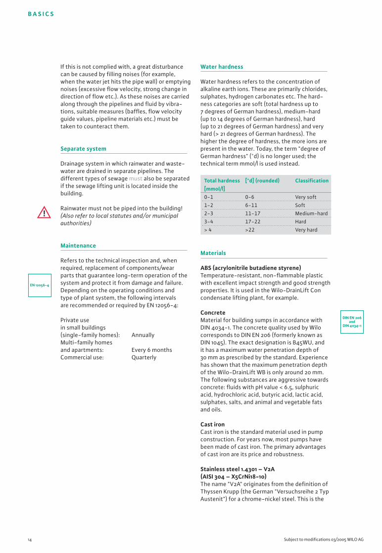
Water hardness
Water hardness refers to the concentration ofalkaline earth ions. These are primarily chlorides,sulphates, hydrogen carbonates etc. The hard-ness categories are soft (total hardness up to7 degrees of German hardness), medium-hard(up to 14 degrees of German hardness), hard(up to 21 degrees of German hardness) and veryhard (> 21 degrees of German hardness). Thehigher the degree of hardness, the more ions arepresent in the water. Today, the term "degree ofGerman hardness" (°d) is no longer used; thetechnical term mmol/l is used instead.
Materials
ABS (acrylonitrile butadiene styrene)Temperature-resistant, non-flammable plasticwith excellent impact strength and good strengthproperties. It is used in the Wilo-DrainLift Concondensate lifting plant, for example.
ConcreteMaterial for building sumps in accordance withDIN 4034-1. The concrete quality used by Wilocorresponds to DIN EN 206 (formerly known asDIN 1045). The exact designation is B45WU, andit has a maximum water penetration depth of30 mm as prescribed by the standard. Experiencehas shown that the maximum penetration depthof the Wilo-DrainLift WB is only around 20 mm.The following substances are aggressive towardsconcrete: fluids with pH value < 6.5, sulphuricacid, hydrochloric acid, butyric acid, lactic acid,sulphates, salts, and animal and vegetable fatsand oils.
Cast ironCast iron is the standard material used in pumpconstruction. For years now, most pumps havebeen made of cast iron. The primary advantagesof cast iron are its price and robustness.
Stainless steel 1.4301 – V2A (AISI 304 – X5CrNi18-10)The name "V2A" originates from the definition ofThyssen Krupp (the German "Versuchsreihe 2 TypAustenit") for a chrome-nickel steel. This is the
Total hardness [°d] (rounded) Classification[mmol/l]0-1 0-6 Very soft
1-2 6-11 Soft
2-3 11-17 Medium-hard
3-4 17-22 Hard
> 4 >22 Very hard
EN 12056-4
DIN EN 206and
DIN 4034-1

Material No.
Austenitic steels
1.4301
1.4401
1.4404
1.4571
B A S I C S
Wilo Sewage Engineering Planning Guide 2005 15
stainless steel standard generally used in thepump industry, which combines good strengthproperties with good temperature resistance.In addition, the material has very good resistanceto organic solutions. (Also refer to "Materialsproperties" on page 16)
Stainless steel 1.4404 – V4A (AISI 316L – X2CrNiMo17-12-2)The name "V4A" originates from the definition ofThyssen Krupp (the German "Versuchsreihe 4 TypAustenit") and refers to a more highly alloyedstainless steel (compared to 1.4301) with a molyb-denum component that can sometimes also beused in sea water. High strength and elasticity aredistinguishing characteristics that make stainlesssteel superior to cast iron. (Also refer to "Materi-als properties" on page 16)
HDPE (high-density polyethylene)The most frequently used pipe material for sewerpipelines, with very good chemical resistance andextremely low surface roughness to prevent de-posits and flow losses. Additional advantages arehigh impact strength and tensile strength withlittle temperature effect. The material PE100 isbeing used more and more in practical applica-tions, where it is replacing PE80 and nodulargraphite iron. Advantages such as pipe insertionfor renovations provide a high cost savings poten-tial (also refer to "Materials properties" on page 16)
PP (polypropylene)Temperature resistance and chemical resistanceare the distinguishing features of this material.Due to the high impact strength of the material,it is extremely robust. (Also refer to "Materialsproperties" on page 16)
PUR (polyurethane)PUR is available in many variations. Baydur GS,which has proven itself in industrial applicationsand is also used by Wilo, features high chemicalresistance, for example to dilute acids, alkalines,motor oils, fats, petrols etc., and corrosion andmicrobial resistance. These outstanding advan-tages make it ideally suited for use in aggressivefluids. It also features superior wear resistance,resistance to rotting, weather resistance, ther-moforming resistance and impact strength, all ata significantly lower weight than metallic materi-als such as cast iron. (Also refer to "Materialsproperties" on page 16)
PVC (polyvinyl chloride)PE sumps are designed in accordance with DIN19537-1 and provide great advantages comparedto conventional concrete sumps, including dura-bility, flexibility, ease of installation and reducedinstallation costs. This flame-retardant materialunites mechanical strength and chemical resist-ance. (Also refer to "Materials properties" onpage 16)
DIN 8078
Materials-standards table
DIN description US description Chemical abbreviation StandardEuropean American
AISI
304
316
316 L
316 Ti
X5CrNi18-9
X5CrNiMo17-12-2
X2CrNiMo17-12-2
X6CrNiMoTi17-12-2
EN
10088-3
10088-3
10088-3
10088-3
ASTM
A 167 / 276
A 167 / 276
A 167 / 276
A 167 / 276
DIN 8061
DIN 19537-1and
DIN 8075
100 %
50 %
0 % PEpipe insertion
Cos
ts
PEpipe laying
Nodular graphiteiron pipe laying
B A S I C S
16 Subject to modifications 03/2005 WILO AG
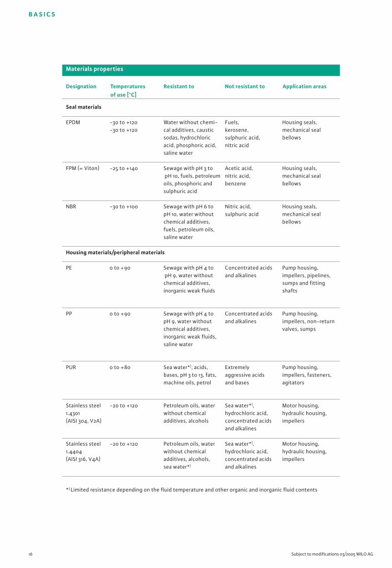
Seal materials
EPDM
FPM (= Viton)
NBR
Materials properties
Designation Temperatures Resistant to Not resistant to Application areasof use [°C]
-30 to +120-30 to +120
-25 to +140
-30 to +100
Water without chemi-cal additives, causticsodas, hydrochloricacid, phosphoric acid,saline water
Sewage with pH 3 topH 10, fuels, petroleumoils, phosphoric andsulphuric acid
Sewage with pH 6 to pH 10, water withoutchemical additives,fuels, petroleum oils,saline water
Fuels, kerosene, sulphuric acid,nitric acid
Acetic acid,nitric acid,benzene
Nitric acid,sulphuric acid
Housing seals, mechanical sealbellows
Housing seals, mechanical sealbellows
Housing seals, mechanical sealbellows
Housing materials/peripheral materials
PE
PP
PUR
Stainless steel1.4301(AISI 304, V2A)
Stainless steel1.4404(AISI 316, V4A)
0 to +90
0 to +90
0 to +80
-20 to +120
-20 to +120
Sewage with pH 4 topH 9, water withoutchemical additives,inorganic weak fluids
Sewage with pH 4 to pH 9, water withoutchemical additives, inorganic weak fluids,saline water
Sea water*), acids,bases, pH 3 to 13, fats,machine oils, petrol
Petroleum oils, waterwithout chemicaladditives, alcohols
Petroleum oils, water without chemicaladditives, alcohols,sea water*)
Concentrated acidsand alkalines
Concentrated acidsand alkalines
Extremelyaggressive acidsand bases
Sea water*),hydrochloric acid,concentrated acidsand alkalines
Sea water*),hydrochloric acid,concentrated acidsand alkalines
Pump housing,impellers, pipelines,sumps and fittingshafts
Pump housing,impellers, non-returnvalves, sumps
Pump housing,impellers, fasteners,agitators
Motor housing, hydraulic housing,impellers
Motor housing, hydraulic housing,impellers
*) Limited resistance depending on the fluid temperature and other organic and inorganic fluid contents

B A S I C S
Wilo Sewage Engineering Planning Guide 2005 17
System curve (pipeline curve)
HDP = Pressure drops (losses) in pipelinesHDF = Pressure drops (losses) in fittingsHgeo = Geodetic height difference
(geodetic height to be overcome) HTot = Total head losses
The system curve shows the delivery headrequired by the system HTot. It consists of thecomponents Hgeo, HDP and HDF. While Hgeo remains(statically) independent of the flow rate, HDP andHDF increase (dynamically) through the differentkinds of losses in pipelines, fittings, mouldedparts, increases in friction due to temperature etc.
Connecting sewer/pipe
In accordance with DIN 4045, describes theconnection between the public sewer and theproperty boundary.
Duty point
The duty point is the point of intersection ofthe system curve and the pump curve. For fixed-speed pumps, the duty point adjusts itself auto-matically.
Example: fluctuating water level in the tank
The duty point changes if, for example, thegeodetic delivery head fluctuates between aminimum and a maximum value in a stationarysewage pumping station. This changes the flowrate supplied by the pump, as the pump can onlyachieve duty points that are on the pump curve.
Reasons for fluctuation of the operating pointcould include different water levels in the sumpor tank, as in this case the intake pressure of thepump changes due to the different levels. On theend discharge side, this change can also becaused by clogging of the pipelines (encrusta-tion) or throttling by valves or consumers.
Discharge pipeline
This term refers to the pipes to the adjacentsystems or pumps. The pipe diameters used arespecified in DIN EN 12050-1 and EN 12056-4. Forsystems without comminution devices, a mini-mum nominal diameter of DN 80 is required; forsystems with comminution devices, it is DN 32.
Water hammer
Water hammers are impacts in the pipeline sys-tem caused by changes in speed. Depending ontheir strength, they can damage or destroy theinstallation. Particularly at risk are installations inwhich the pipes are laid such that they are not ona steady incline or descent. As the water columncan break away at the high points (vacuum for-mation), or increased pressure can be generatedwhen the water columns collide, the pipes canburst.
Particularly at risk for this are very large pipelinesand systems with excessive flow velocities.
Basic hydraulic concepts and pipelines
H
Q
Systemcurve
HVL+HVA
Htot.
Hgeo
HgeoMin. level
System curve 1
A
B
System curve 2
Pump curve
A, B = duty pointsHgeoMax. level
H
Q
DIN 4045
DIN EN12050-1
andEN 12056-4
B A S I C S
18 Subject to modifications 03/2005 WILO AG
Pressure drops in pipelines and fittings
Pressure drops are reductions in pressurebetween the inlet and outlet of the component.These components include pipelines and fittings.The losses are due to turbulence and friction.Each pipeline and fitting has its own specific dropvalue depending on the material and surfaceroughness. Refer to the manufacturer's specifica-tions for specific information. An overview of thefittings used by Wilo and their drop value isprovided in the Annex. (Also refer to Table 6 ofthe Annex, "Pressure drops relative to flow ratesof HDPE plastic pipes")
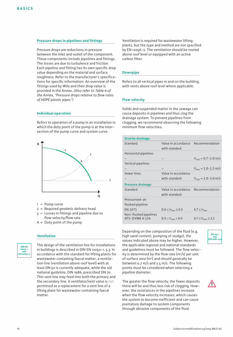
Individual operation
Refers to operation of a pump in an installation inwhich the duty point of the pump is at the inter-section of the pump curve and system curve.
1 = Pump curve2 = Required geodetic delivery head3 = Losses in fittings and pipeline due to
flow velocity/flow rateA = Duty point of the pump
Ventilation
The design of the ventilation line for installationsin buildings is described in DIN EN 12050-1, 5.3. Inaccordance with the standard for lifting plants forwastewater containing faecal matter, a ventila-tion line (ventilation above roof level) with atleast DN 50 is currently adequate, while the oldnational guideline, DIN 1986, prescribed DN 70.This vent line may feed into both the primary andthe secondary line. A ventilator/vent valve is notpermitted as a replacement for a vent line of alifting plant for wastewater containing faecalmatter.
Ventilation is required for wastewater liftingplants, but the type and method are not specifiedby EN 12056-2. The ventilation should be routedabove roof level or equipped with an activecarbon filter.
Downpipe
Refers to all vertical pipes in and on the building,with vents above roof level where applicable.
Flow velocity
Solids and suspended matter in the sewage cancause deposits in pipelines and thus clog thedrainage system. To prevent pipelines fromclogging, we recommend observing the followingminimum flow velocities:
Depending on the composition of the fluid (e.g.high sand content, pumping of sludge), thevalues indicated above may be higher. However,the applicable regional and national standardsand guidelines must be followed. The flow veloc-ity is determined by the flow rate (m3/s) per unitof surface area (m2) and should generally bebetween 0.7 m/s and 2.5 m/s. The followingpoints must be considered when selecting apipeline diameter:
The greater the flow velocity, the fewer depositsthere will be and thus less risk of clogging. How-ever, the resistances in the pipelines increasewhen the flow velocity increases, which causesthe system to become inefficient and can causepremature damage to system componentsthrough abrasive components of the fluid.
H
Q
1
A
3
2
DIN EN12050-1
andEN 12056-2
Gravity drainageStandard Value in accordance Recommendation
with standard
Horizontal pipelines
– – Vmin = 0.7-1.0 m/s
Vertical pipelines
– – Vmin = 1.0-1.5 m/s
Sewer lines Value in accordance
– with standard Vmin = 2.0-3.0 m/s
Pressure drainageStandard Value in accordance Recommendation
with standard
Pressurised-air
flushed pipeline
EN 1671 0.6 ≤ Vmin ≤ 0.9 0.7 ≤ Vmin
Non-flushed pipelinesATV-DVWK A 134 0.5 < Vmin < 0.9 0.7 ≤ Vmin ≤ 2.5
EN 1671and
DIN 1986-100
B A S I C S
Wilo Sewage Engineering Planning Guide 2005 19
Free (ball) passage
Because fluids vary in content and composition,sewage pumps and their hydraulic parts areadapted accordingly. However, it must be consid-ered which impeller design will best suit therespective fluid and its composition.
Note, however, that enlarging the free passagemeans reducing the hydraulic efficiency. As aresult, more motor power is necessary to achievethe same hydraulic results, which affects operat-ing and procurement costs. Therefore, carefuldesign is essential from an economic standpoint.
Gravity drainage line
In a gravity drainage line, drainage is broughtabout by geodetic gradient. The line is filled onlypartially, to the crest of the pipe.
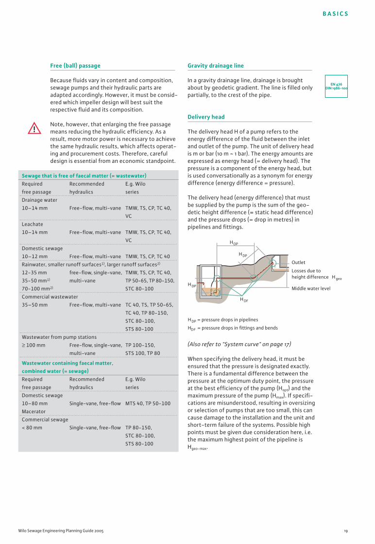
Delivery head
The delivery head H of a pump refers to theenergy difference of the fluid between the inletand outlet of the pump. The unit of delivery headis m or bar (10 m ~ 1 bar). The energy amounts areexpressed as energy head (= delivery head). Thepressure is a component of the energy head, butis used conversationally as a synonym for energydifference (energy difference = pressure).
The delivery head (energy difference) that mustbe supplied by the pump is the sum of the geo-detic height difference (= static head difference)and the pressure drops (= drop in metres) inpipelines and fittings.
(Also refer to "System curve" on page 17)
When specifying the delivery head, it must beensured that the pressure is designated exactly.There is a fundamental difference between thepressure at the optimum duty point, the pressureat the best efficiency of the pump (Hopt) and themaximum pressure of the pump (Hmax). If specifi-cations are misunderstood, resulting in oversizingor selection of pumps that are too small, this cancause damage to the installation and the unit andshort-term failure of the systems. Possible highpoints must be given due consideration here, i.e.the maximum highest point of the pipeline is Hgeo-max.
Sewage that is free of faecal matter (= wastewater)Required Recommended E.g. Wilo
free passage hydraulics series
Drainage water
10–14 mm Free-flow, multi-vane TMW, TS, CP, TC 40,
VC
Leachate
10–14 mm Free-flow, multi-vane TMW, TS, CP, TC 40,
VC
Domestic sewage
10–12 mm Free-flow, multi-vane TMW, TS, CP, TC 40
Rainwater, smaller runoff surfaces1), larger runoff surfaces2)
12-35 mm free-flow, single-vane, TMW, TS, CP, TC 40,
35-50 mm1) multi-vane TP 50-65, TP 80-150,
70-100 mm2) STC 80-100
Commercial wastewater
35–50 mm Free-flow, multi-vane TC 40, TS, TP 50-65,
TC 40, TP 80-150,
STC 80-100,
STS 80-100
Wastewater from pump stations
≥ 100 mm Free-flow, single-vane, TP 100-150,
multi-vane STS 100, TP 80
Wastewater containing faecal matter, combined water (= sewage)Required Recommended E.g. Wilo
free passage hydraulics series
Domestic sewage
10–80 mm Single-vane, free-flow MTS 40, TP 50-100
Macerator
Commercial sewage
< 80 mm Single-vane, free-flow TP 80-150,
STC 80-100,
STS 80-100
EN 476DIN 1986-100
HDP
HDP
HDP
HDF
HDP = pressure drops in pipelines
HDF = pressure drops in fittings and bends
Outlet
Middle water level
Losses due to height difference H geo

B A S I C S
20 Subject to modifications 03/2005 WILO AG
For discharge pipelines that are installed atvarying inclines and have no ventilation, theindividual values must be added according tothe changes in height. This is due to the factthat, because of the individual height differences,it is most probable that the lines will be partiallyfilled, and thus multiple superimposed watercolumns must be added.
For partially-filled lines, the ascending partiallines are added:
Hgeo-max = (NN1 - NN) + (NN3 - NN2) = [10 m - (-1 m)] + (11 m - 5 m) = 17 m
Were we to assume complete filling of the pipe-line system, we would only need to calculate thegeodetic height difference between the middlewater level of the tank and the transfer.
When completely filled:
Hgeo = NNA - NN = 6 m - (-1 m) = 7 m
Aid to calculation:For pump start without ventilation: Add allascending lines (line 1 + line 3), as the air in thedescending line (line 2) is compressed. Therefore,a high pressure is required to overcome the highpoints.
During operation without ventilation: After theair has been pushed out of the pipeline, thepipeline is completely filled. Therefore, thepressure that must be supplied by the pump isonly the maximum geodetic height differenceHgeo between the outlet/transfer NNA and thecut-out water level in the sump NN.
Pump start with ventilation: Here, the pressuredifferential between the water level in the sump(pump cut-in point) and the highest point of thesystem, Hgeo-max, must be considered.
During operation with ventilation: Duringoperation, the pump behaves in the same waydescribed under "without ventilation" above.
Therefore, for proper operation of the pump,complete filling and partial filling amounts mustbe calculated, as the duty point can changedrastically, causing the pump to operate outsidethe permitted ranges.
Flow rate (= delivery rate = flow rate)
The flow rate Q is the hydraulic flow rate suppliedby the pump (quantity of fluid pumped) within acertain unit of time, such as l/s or m3/h. Thecirculation required for internal cooling andleakage losses are power losses which are notincluded when calculating the flow. When speci-fying the quantity to be pumped, it must bespecified whether this is the best point of thepump (Qopt), the maximum required flow rate(Qmax) or the minimum required flow rate (Qmin)in operation.
If specifications are misunderstood, resulting inoversizing or selection of pumps that are toosmall, this can cause damage to the installationand the unit, as well as their short-term failure.
Ground pipe
Refers to the underground drainpipe to thesewer.
NN3 11,0 m
Hgeo-maxHgeo
NN2 5,0 m
NN1 10,0 m
1
2 34
NND 0 mPressure lossPump station
NN -1,0 mCut-out water level
NNA 6,0 mTransfer
During complete filling
B A S I C S
Wilo Sewage Engineering Planning Guide 2005 21
Cavitation (see also NPSH)
Cavitation refers to the formation and implosionof gas bubbles (cavities) as a result of local nega-tive pressure formation under the vaporisationpressure of the fluid at the impeller inlet. Thisresults in decreased output (delivery head) andefficiency, and causes rough running, noise andmaterial damage to the interior of the pump.Through the expansion and collapse (implosion)of tiny air bubbles in areas of higher pressure (for example, in an advanced state, at theimpeller outlet), microscopic explosions causepressure impacts that damage or destroy thehydraulics. The first signs of this are noise fromor damage to the impeller inlet.
The damage to the material depends on itscomposition. Thus, a stainless steel casting1.4408 (AISI 316) is approximately 20 times moreresistant than the standard material of the pumpindustry, cast iron (GG 25). For bronze, twice thelifetime can still be assumed.
Taking advantage of the relationship of flowvelocity, pressure and the corresponding evapo-ration temperature helps to prevent cavitation.A high flow velocity means low pressure, which,in turn, results in a lower boiling point of the fluid.Thus, for example, the formation of gas bubblescan be decreased/prevented by increasing theinlet pressure (for example, by increasing thewater coverage, higher water level in the sump).Additional starting points are provided in thechapter on "Fault diagnostics" on page 67 ff.
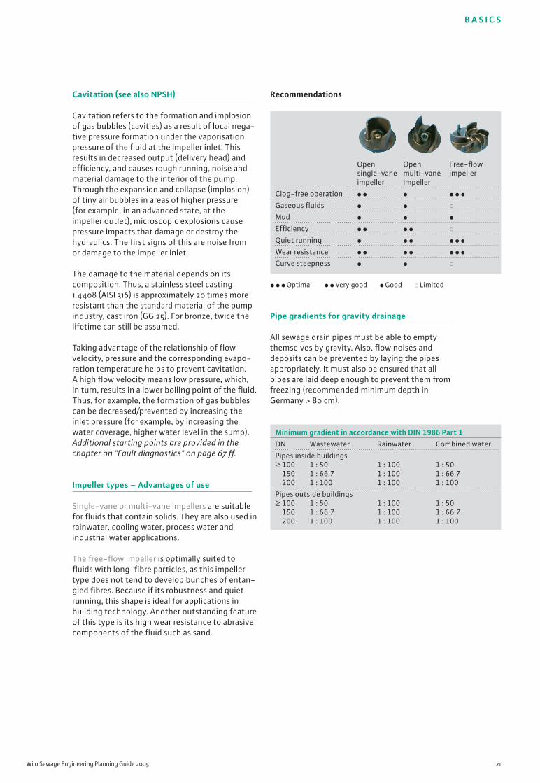
Impeller types – Advantages of use
Single-vane or multi-vane impellers are suitablefor fluids that contain solids. They are also used inrainwater, cooling water, process water andindustrial water applications.
The free-flow impeller is optimally suited tofluids with long-fibre particles, as this impellertype does not tend to develop bunches of entan-gled fibres. Because if its robustness and quietrunning, this shape is ideal for applications inbuilding technology. Another outstanding featureof this type is its high wear resistance to abrasivecomponents of the fluid such as sand.
Recommendations
� � � Optimal � � Very good � Good � Limited
Pipe gradients for gravity drainage
All sewage drain pipes must be able to emptythemselves by gravity. Also, flow noises anddeposits can be prevented by laying the pipesappropriately. It must also be ensured that allpipes are laid deep enough to prevent them fromfreezing (recommended minimum depth inGermany > 80 cm).
Open Open Free-flowsingle-vane multi-vane impellerimpeller impeller
Clog-free operation � � � � � �
Gaseous fluids � � �
Mud � � �
Efficiency � � � � �
Quiet running � � � � � �
Wear resistance � � � � � � �
Curve steepness � � �
Minimum gradient in accordance with DIN 1986 Part 1DN Wastewater Rainwater Combined water
Pipes inside buildings≥ 100 1 : 50 1 : 100 1 : 50
150 1 : 66.7 1 : 100 1 : 66.7200 1 : 100 1 : 100 1 : 100
Pipes outside buildings≥ 100 1 : 50 1 : 100 1 : 50
150 1 : 66.7 1 : 100 1 : 66.7200 1 : 100 1 : 100 1 : 100

B A S I C S
22 Subject to modifications 03/2005 WILO AG
to keep it in a fluid state. Pump factors thataffect the NPSH are the impeller type and pumpspeed. Environmental factors that affect it arethe fluid temperature, water coverage andatmospheric pressure. There are two differenttypes of NPSH value:
1. NPSH pump = NPSH requiredSpecifies the intake pressure necessary to preventcavitation. The water coverage (height differencebetween pump inlet and the water level in thesump) is also considered inlet pressure.
2. NPSH system = NPSH presentSpecifies the pressure present at the pump inlet.
NPSHsystem > NPSHpump or NPSHpresent > NPSHrequired
For pumps in wet sump installation, the NPSHsystem is calculated by adding the atmos-pheric pressure and the fluid coverage of thepump, minus the vaporisation pressure. In drysump installation, the inlet-side pressure headlosses are also subtracted. The NPSHpump is speci-fied by the manufacturer with the definition of acavitation criterion.
Parallel connection
The objective of parallel opera-tion is to increase the flow rate;the term refers to operation of2 or more pumps, where allpumps discharge simultane-ously into a shared dischargepipeline (with each pumphaving its own correspondingfittings and its own supplylines). If all pumps are pumpingsimultaneously, the flow rates can be added atthe same delivery head in order to calculate thetotal delivery head.
As is true for individual operation, the duty pointof the pump curve is obtained from the point ofintersection of the pump curve with the systemcurve. Each pump continues to work at its ownpump curve. For pumps of the same type, thismeans that all pumps the have the same flow rate (also refer to the graphic on page 23). Note,however, that the supply line to the collectingdischarge pipeline has its own fittings withcorresponding losses. These must be subtractedwhen calculating the duty point.
Range of performance Minimum Reference to gradient standard
and sectionNon-ventilated 1.0% DIN EN 12056-2,connection pipes Table 5
DIN 1986-100,Section 8.3.2.2
Ventilated 0.5% DIN EN 12056-2,connection pipes Table 8
Ground and collecting pipesa) For wastewater 0.5% DIN 1986-100,
Section 8.3.4,Section 8.3.5
b) For rainwater 0.5% DIN 1986-100,(filling level 0.7) Section 9.3.5.2
Ground and collecting pipes 0.5% DIN 1986-100,DN 90 (toilet bowl with Table A.2flush water volume of 4.5 l-6 l)
Ground pipe for rain- 0.5% DIN 1986-100,water outside the Section 9.3.5.2building (filling level 0.7)
up to DN 200 0.5%from DN 250 1:DN*
EN 1671
DIN EN12050-1
EN 12056-4
Minimum gradient
* Flow velocity of at least 0.7 m/s up to max. 2.5 m/s.
Behind a sump with open flow-through, it ispossible to work toward complete filling withoutpositive pressure.
Minimum nominal diameter
Refers to the smallest nominal diameter (connec-tion dimension) in an installation or the smallestrequired pipe dimension.
Reserve impoundment volume
The reserve impoundment volume indicates theadditional protection provided against fluid leaks.It is based on the average daily volume of waste-water generated, and is specified as 25% of thatfigure. It is equal to the additional volume thatmust be provided between the cut-in point ofthe pump system and any fluid leaks. In practice,the inlet-side volume of the pipeline is includedin the calculation as a safety factor.
NPSH (see also Cavitation)
One important value for a centrifugal pump is theNPSH (Net Positive Suction Head). This specifiesthe minimum pressure at the pump inlet that isrequired by this pump type to work withoutcavitation, meaning the additional pressurerequired to prevent evaporation of the fluid and
B A S I C S
Wilo Sewage Engineering Planning Guide 2005 23
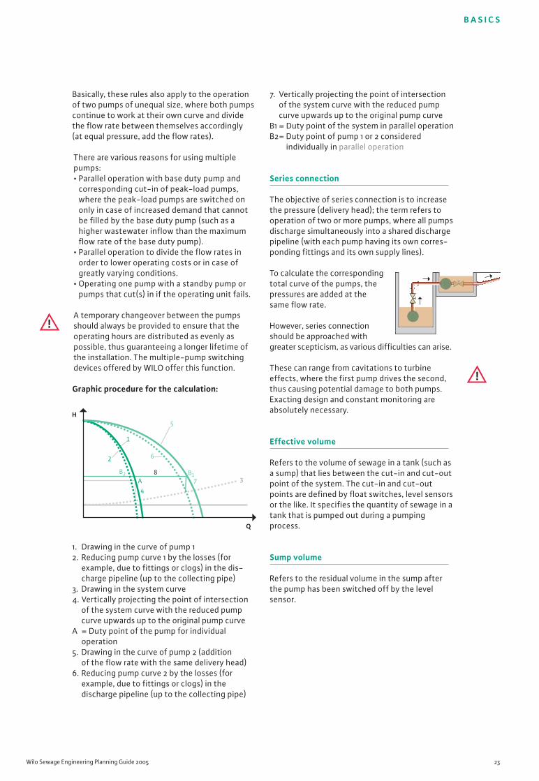
Basically, these rules also apply to the operationof two pumps of unequal size, where both pumpscontinue to work at their own curve and dividethe flow rate between themselves accordingly(at equal pressure, add the flow rates).
There are various reasons for using multiplepumps:• Parallel operation with base duty pump and
corresponding cut-in of peak-load pumps,where the peak-load pumps are switched ononly in case of increased demand that cannotbe filled by the base duty pump (such as ahigher wastewater inflow than the maximumflow rate of the base duty pump).
• Parallel operation to divide the flow rates inorder to lower operating costs or in case ofgreatly varying conditions.
• Operating one pump with a standby pump orpumps that cut(s) in if the operating unit fails.
A temporary changeover between the pumpsshould always be provided to ensure that theoperating hours are distributed as evenly aspossible, thus guaranteeing a longer lifetime ofthe installation. The multiple-pump switchingdevices offered by WILO offer this function.
Graphic procedure for the calculation:
1. Drawing in the curve of pump 12. Reducing pump curve 1 by the losses (for
example, due to fittings or clogs) in the dis-charge pipeline (up to the collecting pipe)
3. Drawing in the system curve4. Vertically projecting the point of intersection
of the system curve with the reduced pump curve upwards up to the original pump curve
A = Duty point of the pump for individual operation
5. Drawing in the curve of pump 2 (addition of the flow rate with the same delivery head)
6. Reducing pump curve 2 by the losses (for example, due to fittings or clogs) in the discharge pipeline (up to the collecting pipe)
7. Vertically projecting the point of intersection of the system curve with the reduced pumpcurve upwards up to the original pump curve
B1 = Duty point of the system in parallel operationB2= Duty point of pump 1 or 2 considered
individually in parallel operation
Series connection
The objective of series connection is to increasethe pressure (delivery head); the term refers tooperation of two or more pumps, where all pumpsdischarge simultaneously into a shared dischargepipeline (with each pump having its own corres-ponding fittings and its own supply lines).
To calculate the correspondingtotal curve of the pumps, thepressures are added at thesame flow rate.
However, series connectionshould be approached withgreater scepticism, as various difficulties can arise.
These can range from cavitations to turbineeffects, where the first pump drives the second,thus causing potential damage to both pumps.Exacting design and constant monitoring areabsolutely necessary.
Effective volume
Refers to the volume of sewage in a tank (such asa sump) that lies between the cut-in and cut-outpoint of the system. The cut-in and cut-outpoints are defined by float switches, level sensorsor the like. It specifies the quantity of sewage in atank that is pumped out during a pumpingprocess.
Sump volume
Refers to the residual volume in the sump afterthe pump has been switched off by the levelsensor.
H
Q
B2 B1A
4
2
8
6
5
1
7 3
B A S I C S
24 Subject to modifications 03/2005 WILO AG
Starting current
This refers to the current required during theprocess of starting up a machine to overcomefriction losses and starting torques. Dependingon the type of start, the starting current can beup to seven times the nominal current. If theelectrical mains are unstable or larger motors areused, appropriate devices must be provided toreduce the starting current. These devices can besoft starters, frequency converters or the like. Areduction of the starting current can already beachieved by selecting a star-delta motor which,in Germany, is specified by the local energycompanies for motor power P2 > 4 kilowatts.
ATEX
See "Explosion protection" on page 24
Operating modes (in accordance with DIN EN 60034-1)
S1 = Continuous dutyThe motor temperature increases during opera-tion up to the operating temperature (thermalsteady state). During operation, the heat isdissipated by coolant or the surrounding fluid.The machine can be operated in this state with-out interruption. The installation type (abovewater/underwater) or installation specified mustalso be taken into consideration. Continuousduty provides no information about this. S1 doesnot explicitly mean 24 hours a day, 7 days a week!
Please note the service life specifications andrunning times per year provided in the relevantdocumentation.
S2 to S9The motor cannot be operated continuously, asthe power loss that is converted to heat in themotor exceeds the amount that could be dissi-pated by the cooling. The motor would eventuallyoverheat and possibly switch off via the motorprotection.
S3This operating mode is a common load forsewage pumps. It specifies a ratio of operatingtime to down time. Both values must be visible onthe type plate and/or in the operating instruc-tions. For S3 mode, the calculation always relatesto a time period of 10 minutes.
Examples:S3 – 20% means: Operating time is 20%
of 10 min. = 2 min.Down time is 80%of 10 min. = 8 min.
S3 – 3 min. means: Operating time is 3 min.Down time is 7 min.
If two values are specified, this means, for example:S3 – 5 min./20 min. Operating time is 5 min
Down time is 15 minS3 – 25%/20 min. Operating time is 5 min.
Down time is 15 min.
Bus technology
Bus technology refers to the intelligent network-ing of electrical components. Here, the bus lineis the data highway on which information is exchanged. A great variety of systems are avail-able on the market today. (Also refer to "LON" onpage 26)
Individual run signal
The individual run signal indicates the operationof the unit (not the operational readiness!).
Individual fault signal
Indicates a fault of the individual pump andprovides an accurate evaluation method forbuilding management systems.
Explosion protection
Explosion protection has been modified in theEU. The European Directive 94/9/EC for explosionprotection has been in effect since July 1, 2003.The modifications generally lie in the fact thatthe entire unit (not just the electrical part) mustbe checked and certified with regard to explosionprotection aspects. It is the responsibility of theowner/management to define the zone in whichexplosion protection must be provided. The unitsthat Wilo certifies as protected from explosionare designed for Zone 1 Group II, Category 2, i.e.for a high standard of safety and where poten-tially explosive atmospheres are expected toexist.
Basic electrical concepts and their influences
B A S I C S
Wilo Sewage Engineering Planning Guide 2005 25
Explosion protectionFor example, EEx de IIB T4
EEx General abbreviation
de Abbreviation for type of protectiond Pressure-resistant casingo Oil immersionp Overpressure casingq Sand-filled apparatuse Increased safetyi Intrinsically safe
II Abbreviation for the group of the electrical apparatusI Mining industriesII Surface industries
B Subdivision of group IIA – B – CDifferent dimensions for border gaps, Minimum ignition current
T4 Abbreviation for the temperature classT1 < 450 ºCT2 < 300 ºCT3 < 200 ºCT4 < 135 ºCT5 < 100 ºCT6 < 85 ºC
Ex isolating relay
When used along with Ex isolating relays, floatswitches can also be used in potentially explosiveenvironments (Zone 1 for fluids containing faecalmatter). These relays reduce the flow of currentto a level at which, even in case of fault, noigniting spark is generated that would cause thefluid or its environment to ignite.
IP protection classes
The number used to designate the IP classifica-tion is composed of two areas. The first digitidentifies the protection against contact andagainst foreign objects, while the second indi-cates the degree of protection from water. Thetable that appears here shows reference values.Information that is more detailed is provided inEN 60034-5 and IEC 34-5.
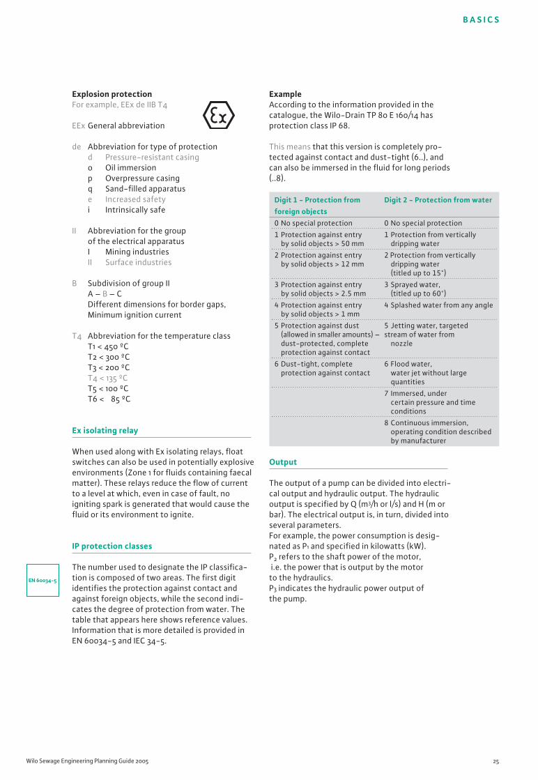
ExampleAccording to the information provided in thecatalogue, the Wilo-Drain TP 80 E 160/14 hasprotection class IP 68.
This means that this version is completely pro-tected against contact and dust-tight (6..), andcan also be immersed in the fluid for long periods(..8).
Output
The output of a pump can be divided into electri-cal output and hydraulic output. The hydraulicoutput is specified by Q (m3/h or l/s) and H (m orbar). The electrical output is, in turn, divided intoseveral parameters. For example, the power consumption is desig-nated as P1 and specified in kilowatts (kW).P2 refers to the shaft power of the motor,i.e. the power that is output by the motor to the hydraulics. P3 indicates the hydraulic power output ofthe pump.
EN 60034-5
Digit 1 - Protection from Digit 2 - Protection from waterforeign objects0 No special protection 0 No special protection
1 Protection against entry 1 Protection from verticallyby solid objects > 50 mm dripping water
2 Protection against entry 2 Protection from vertically by solid objects > 12 mm dripping water
(titled up to 15°)
3 Protection against entry 3 Sprayed water,by solid objects > 2.5 mm (titled up to 60°)
4 Protection against entry 4 Splashed water from any angleby solid objects > 1 mm
5 Protection against dust 5 Jetting water, targeted(allowed in smaller amounts) – stream of water fromdust-protected, complete nozzleprotection against contact
6 Dust-tight, complete 6 Flood water,protection against contact water jet without large
quantities
7 Immersed, under certain pressure and timeconditions
8 Continuous immersion, operating condition described by manufacturer
B A S I C S
26 Subject to modifications 03/2005 WILO AG
U = Voltage [V]I = Current strength[A]cos� = Specification
of the motor manufacturerM = Nominal torque [Nm]n = Nominal speed [rpm]� = Fluid density [g/dm3]g = 9.81 m/s2Q = Flow rate [m3/h]H = Delivery head [m]
LON (Local Operating Network)
Refers to an automation network (such as forbuilding automation) that distributes responsibil-ities (intelligences) to decentralised componentssuch as the pump, switching device etc. Throughthe use of a standardised protocol, all functionscan be evaluated at corresponding nodes. Themodular structure of the network provides con-tinuous flexibility and expandability. A standard-ised structure is no longer required, as all systemcomponents can transmit their information in alldirections. (Also refer to "Bus technology" onpage 24)
Motor protection
Thermal overcurrent relays (such as PTC thermistors)These relays are tripped by temperature andinterrupt the operation of the unit. They aretripped at certain temperatures (as a result ofthe temperature increase of the winding) and byincreased current consumption. This heating maybe caused by blocked hydraulics or by voltagefluctuations.
Motor protection switchMotor protection switches are built into switch-ing devices to protect electrical apparatus. Theyswitch the motor on or off according to its break-ing capacity and excessive input voltages. Theyalso serve as protective devices against short-circuit and phase failure. They are tripped byPTOs (bimetallic switches) and PTCs.
Integrated temperature sensorsThese temperature sensors are integrated toprotect against overheating in the winding of themotor. This guarantees direct temperature moni-toring at the winding.
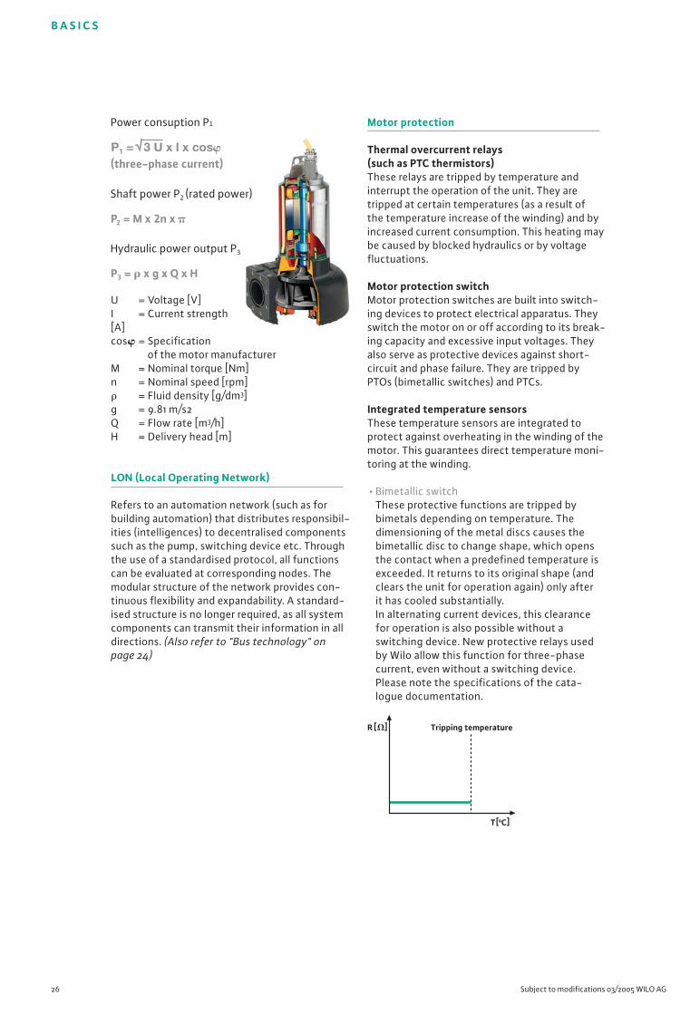
• Bimetallic switchThese protective functions are tripped bybimetals depending on temperature. Thedimensioning of the metal discs causes thebimetallic disc to change shape, which opensthe contact when a predefined temperature isexceeded. It returns to its original shape (andclears the unit for operation again) only afterit has cooled substantially.In alternating current devices, this clearancefor operation is also possible without aswitching device. New protective relays usedby Wilo allow this function for three-phasecurrent, even without a switching device.Please note the specifications of the cata-logue documentation.
Power consuption P1
(three-phase current)
P2 = M x 2n x
Shaft power P2 (rated power)
P3 = � x g x Q x H
Hydraulic power output P3
R [�] Tripping temperature
T[oC]
B A S I C S
Wilo Sewage Engineering Planning Guide 2005 27
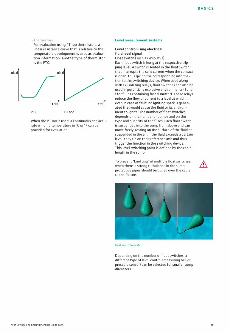
• ThermistorsFor evaluation using PT 100 thermistors, alinear resistance curve that is relative to thetemperature development is used as evalua-tion information. Another type of thermistoris the PTC.
PTC PT 100
When the PT 100 is used, a continuous and accu-rate winding temperature in °C or °F can beprovided for evaluation.
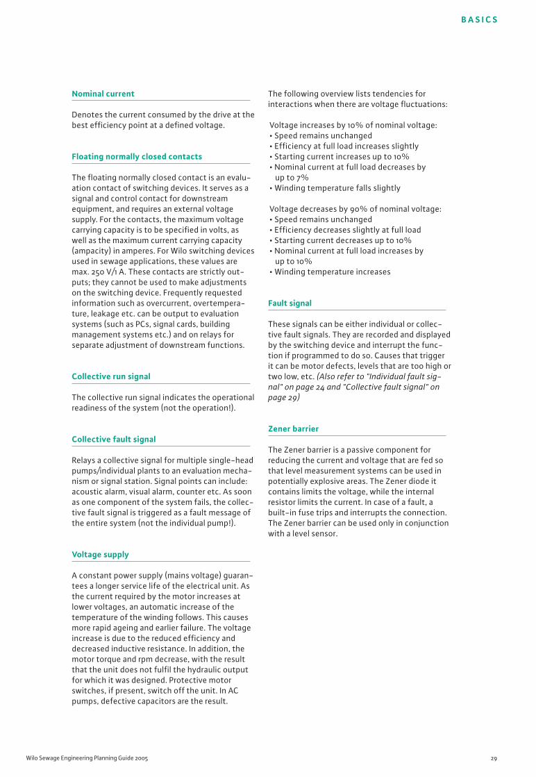
Level measurement systems
Level control using electrical fluid level signalFloat switch (such as Wilo MS 1)Each float switch is hung at the respective trip-ping level. A switch is seated in the float switchthat interrupts the sent current when the contactis open, thus giving the corresponding informa-tion to the switching device. When used alongwith Ex isolating relays, float switches can also beused in potentially explosive environments (Zone1 for fluids containing faecal matter). These relaysreduce the flow of current to a level at which,even in case of fault, no igniting spark is gener-ated that would cause the fluid or its environ-ment to ignite. The number of float switchesdepends on the number of pumps and on thetype and quantity of the fuses. Each float switchis suspended into the sump from above and canmove freely, resting on the surface of the fluid orsuspended in the air. If the fluid exceeds a certainlevel, they tip on their reference axis and thustrigger the function in the switching device.This level switching point is defined by the cablelength in the sump.
To prevent "knotting" of multiple float switcheswhen there is strong turbulence in the sump,protective pipes should be pulled over the cableto the fixture.
Float switch (Wilo MS 1)
Depending on the number of float switches, adifferent type of level control (measuring bell orpressure sensor) can be selected for smaller sumpdiameters.
R [�] R [�]
T[oC]T[oC]

B A S I C S
28 Subject to modifications 03/2005 WILO AG
Level control via hydrostatic trip signalIn this type of signal measurement, the fluidlevel is measured via the ambient pressure of adiaphragm. This ambient pressure is caused bythe surrounding fluid. This information can berelayed electrically (analogue) or via a pressuresignal (pneumatically). There is no regulation ofthe fluid level in the sump until settings areconfigured on the switching gear (unlike floatswitches).
Measuring bell (diving bell)Because of the greater area of its opening, themeasuring bell is suitable for highly contami-nated fluids. Cast iron is used as the material forthe diving bell so that it remains submersed, evenin higher-density fluids, due to its heavierweight. When the measuring bell is covered bythe fluid, the trapped atmospheric air is com-pressed by an amount that corresponds to thelevel. This change in pressure is evaluated by anelectronic level transducer located on or in theswitching device and calibrated to the values inthe switching device. It offers the particularadvantage of continuous level measurementwith levels that can be evaluated (in centimetres,metres etc.) and can be used in potentially explo-sive areas (such as sewage containing faecalmatter Zone 1) by relaying a pure pressure signal,without additional safety effort, in the bubbleaeration method. It is evaluated in the switchingdevice using the device's integrated sensors.
The bubble aeration method (air compressor)guarantees a uniform quantity of air in thesystem.
Measuring bell
Electronic pressure sensorElectronic pressure sensors function according tothe same principle as diving bells. The primarydifference is that the pressure transducer isdirectly integrated into the pressure sensor,meaning that the pressure signal is convertedinto an analogue electrical signal (4-20 mA)directly in the sump. Accordingly, the switchingdevice does not require an additional pressuretransducer. When the diving bell is used, inaccu-racies can be caused by such factors as leakage inthe pressure hose or thermal changes with corre-sponding effects on the quantity of air in thehose. Evaluation using an electronic pressuresensor is more precise. In addition, the materialused in pressure sensors is more corrosion-resistant (usually AISI 316 or better). The sensor isinstalled suspended in the sump; when there isstrong turbulence in the fluid, it can be installedin a protective pipe. The sensor used by Wilo canbe used in potentially explosive environments.However, as is true for all sensors, a Zener barriermust be used to prevent ignition sparks that cancause explosions in the event of failures/defects.
Electronic pressure sensor
For increased safety, an additional Wilo MS 1 floatswitch could be installed as a high water alarm.
B A S I C S
Wilo Sewage Engineering Planning Guide 2005 29
Nominal current
Denotes the current consumed by the drive at thebest efficiency point at a defined voltage.
Floating normally closed contacts
The floating normally closed contact is an evalu-ation contact of switching devices. It serves as asignal and control contact for downstreamequipment, and requires an external voltagesupply. For the contacts, the maximum voltagecarrying capacity is to be specified in volts, aswell as the maximum current carrying capacity(ampacity) in amperes. For Wilo switching devicesused in sewage applications, these values aremax. 250 V/1 A. These contacts are strictly out-puts; they cannot be used to make adjustmentson the switching device. Frequently requestedinformation such as overcurrent, overtempera-ture, leakage etc. can be output to evaluationsystems (such as PCs, signal cards, buildingmanagement systems etc.) and on relays forseparate adjustment of downstream functions.
Collective run signal
The collective run signal indicates the operationalreadiness of the system (not the operation!).
Collective fault signal
Relays a collective signal for multiple single-headpumps/individual plants to an evaluation mecha-nism or signal station. Signal points can include:acoustic alarm, visual alarm, counter etc. As soonas one component of the system fails, the collec-tive fault signal is triggered as a fault message ofthe entire system (not the individual pump!).
Voltage supply
A constant power supply (mains voltage) guaran-tees a longer service life of the electrical unit. Asthe current required by the motor increases atlower voltages, an automatic increase of thetemperature of the winding follows. This causesmore rapid ageing and earlier failure. The voltageincrease is due to the reduced efficiency anddecreased inductive resistance. In addition, themotor torque and rpm decrease, with the resultthat the unit does not fulfil the hydraulic outputfor which it was designed. Protective motorswitches, if present, switch off the unit. In ACpumps, defective capacitors are the result.
The following overview lists tendencies forinteractions when there are voltage fluctuations:
Voltage increases by 10% of nominal voltage:• Speed remains unchanged• Efficiency at full load increases slightly• Starting current increases up to 10%• Nominal current at full load decreases by
up to 7%• Winding temperature falls slightly
Voltage decreases by 90% of nominal voltage:• Speed remains unchanged• Efficiency decreases slightly at full load• Starting current decreases up to 10%• Nominal current at full load increases by
up to 10%• Winding temperature increases
Fault signal
These signals can be either individual or collec-tive fault signals. They are recorded and displayedby the switching device and interrupt the func-tion if programmed to do so. Causes that triggerit can be motor defects, levels that are too high ortwo low, etc. (Also refer to "Individual fault sig-nal" on page 24 and "Collective fault signal" onpage 29)
Zener barrier
The Zener barrier is a passive component forreducing the current and voltage that are fed sothat level measurement systems can be used inpotentially explosive areas. The Zener diode itcontains limits the voltage, while the internalresistor limits the current. In case of a fault, abuilt-in fuse trips and interrupts the connection.The Zener barrier can be used only in conjunctionwith a level sensor.

Wilo Sewage Engineering Planning Guide 2005 31
General instructions
• The flow rate to be supplied by the pumpmust exceed the flow rate of the sewageinflow. Ensure that the pumps run at theiroptimal duty point wherever possible in orderto guarantee a long service life and optimaloutput.
• Consider that the output of the pumpdecreases as its age increases. Abrasion andcorrosion can have a negative effect on theflow rates and pressures.
• Design the pump so that it is within a range of +/-15% of its best efficiency point.
• Steep pump curves prevent clogging of thedischarge pipeline, as when counterpressureis increased, the pump also increases thepressure along its curve, thus flushing awaydeposits.
• When selecting accessories, consider theproperties of the materials with regard totheir ability to resist corrosion and abrasion.
• For high geodetic delivery heads, use quick-closing fittings to reduce water hammer.
• For reasons of economy and safety technol-ogy, compensate for peak inflows by usingtwin-head pump units (pump splitting,standby pump is always to be consideredseparately).
• If the transfer point (sewer) is below the sumplevel, vents should be provided, as otherwisethe generated suction could completely drainthe entire sump, including the pump. Thiswould result in ventilation problems; there-fore, appropriate precautions should be takenin advance.
• Note the different operating conditions forpipelines that are laid at varying inclines. Thesituation with regard to partial or completefilling should be considered! (Also refer to"Delivery head" on page 19/20)
Pipeline and pump materials
• When designing the system, note that thefollowing influences could mean additionalstress for your system:
• Flow velocity of the fluid > Noise, wear• pH value of the fluid > Material damage,
corrosion• Chemical components of the fluid
> Corrosion• Atmospheric conditions such as humidity,
salt content of the air etc. > Corrosion• External temperature and fluid temperature
> Fluid aggressiveness, corrosion• Retention period of the fluid in the pipeline
> Odour build-up
• Because of the changes in materials and theresulting changes in pressure rating, PN 10pipes should always be used for underground pipelines.
Installation and calculationexamplesGeneral instructions for calculation
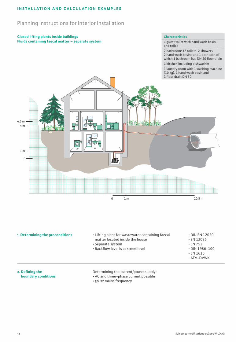
I N S TA L L AT I O N A N D C A L C U L AT I O N E X A M P L E S
32 Subject to modifications 03/2005 WILO AG
• DIN EN 12050• EN 12056• EN 752• DIN 1986-100• EN 1610• ATV-DVWK
Planning instructions for interior installation
Closed lifting plants inside buildingsFluids containing faecal matter – separate system
1 m 10.5 m0
4.5 m4 m
1 m
0
1. Determining the preconditions
2. Defining the boundary conditions
• Lifting plant for wastewater containing faecalmatter located inside the house
• Separate system• Backflow level is at street level
Determining the current/power supply:• AC and three-phase current possible• 50 Hz mains frequency
Characteristics1 guest toilet with hand wash basin and toilet
2 bathrooms (2 toilets, 2 showers,2 hand wash basins and 1 bathtub), ofwhich 1 bathroom has DN 50 floor drain
1 kitchen including dishwasher
1 laundry room with 1 washing machine (10 kg), 1 hand wash basin and 1 floor drain DN 50
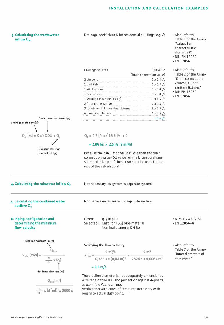
I N S TA L L AT I O N A N D C A L C U L AT I O N E X A M P L E S
Wilo Sewage Engineering Planning Guide 2005 33
3. Calculating the wastewater inflow Qw
Drain connection value [l/s]
Drainage coefficient [l/s]
Drainage value for
special load [l/s]
4. Calculating the rainwater inflow Qr
5. Calculating the combined wateroutflow Qc
6. Piping configuration anddetermining the minimumflow velocity
Required flow rate [m3/h]
Pipe inner diameter [m]
Drainage coefficient K for residential buildings: 0.5 l/s
= 2.04 l/s > 2.5 l/s (9 m3/h)
Because the calculated value is less than the drainconnection value (DU value) of the largest drainagesource, the larger of these two must be used for therest of the calculation!
Not necessary, as system is separate system
Not necessary, as system is separate system
Given: 15.5 m pipeSelected: Cast iron (GG) pipe material
Nominal diameter DN 80
Verifying the flow velocity
= 0.5 m/s
The pipeline diameter is not adequately dimensionedwith regard to losses and protection against deposits,as 0.7 m/s < Vmin < 2.5 m/s. Verification with curve of the pump necessary withregard to actual duty point.
• Also refer to Table 1 of the Annex, "Values for characteristicdrainage K"
• DIN EN 12050• EN 12056
• Also refer to Table 2 of the Annex, "Drain connectionvalues (DU) forsanitary fixtures"
• DIN EN 12050• EN 12056
• ATV-DVWK A134• EN 12056-4
• Also refer to Table 7 of the Annex, "Inner diameters ofnew pipes"
Qs [l/s] = K x DU + Qb
Vmin [m/s] =Qben
x (di)2
4π
Qben [m3]
x (di[m])2 x 3600 s4π
Qs = 0,5 l/s x 16,6 l/s + 0
Vmin = =9 m3/h
0,785 s x (0,08 m) 2
9 m3
2826 s x 0,0064 m2
Drainage sources DU value
(Drain connection value)
2 showers 2 x 0.8 l/s
1 bathtub 1 x 0.8 l/s
1 kitchen sink 1 x 0.8 l/s
1 dishwasher 1 x 0.8 l/s
1 washing machine (10 kg) 1 x 1.5 l/s
2 floor drains DN 50 2 x 0.8 l/s
3 toilets with 9 l flushing cisterns 3 x 2.5 l/s
4 hand wash basins 4 x 0.5 l/s
16.6 l/s
7. Selecting the required fittings
8. Calculating the required totaldelivery head
A. Geodetic height difference
Hgeo-max [m] = NN1 - NN0
Height of transfer Height of water level
or pipe bottom [m]
of the backflow loop
in the reversal point [m]
B. Losses in pipelines
HDP [m] = H*DP x L
Pipeline losses Pipeline
acc. to diagram length [m]
C. Losses in fittings
HDF [m] = (HDF1 + HDF2… + HDFn) x H*DP
Losses in Losses in Losses in
fitting 1 fitting 2 pipelines
[m] [m] acc. to diagram
D. Total losses
HTot [m] = Hgeo-max + HDF + HDP
Geodetic Losses in Losses
height fittings in pipe-
difference [m] lines
[m] [m]
1 x shut-off valve DN 80 � 0.56 m1 x check valve DN 80 � 3.3 m5 x bends 90° DN 80 � 3.95 m
Hgeo-max = 4.5 m - 0 m
= 4.5 m
According to diagram for 15.5 m cast iron pipe, DN 80, new:
H*DP = 0.45 m/100 m
corresponds to 0.0045 m/m of pipeline
HDP = 0.0045 x 15.5 m
= 0.07 m
HDF = (0.56 m + 3.3 m + 3.95 m) x 0.0045
= 0.035 m
HTot = 4.5 m + 0.07 m + 0.035 m
= 4.61 m
Calculated duty point (minimum value):Qmax = 9 m3/h (2.5 l/s)Htot = 4.61 m
• Also refer to Table 9 of theAnnex, "Losses in fittings"
• DIN EN 12050-1• DIN 1988-T3
• Also refer to Table 8 of theAnnex, "Pipe frictionlosses and correc-tion factors"
• Also refer to Table 9 of theAnnex, "Losses in fittings"
• DIN EN 12050-1• DIN 1988-T3
I N S TA L L AT I O N A N D C A L C U L AT I O N E X A M P L E S
34 Subject to modifications 03/2005 WILO AG
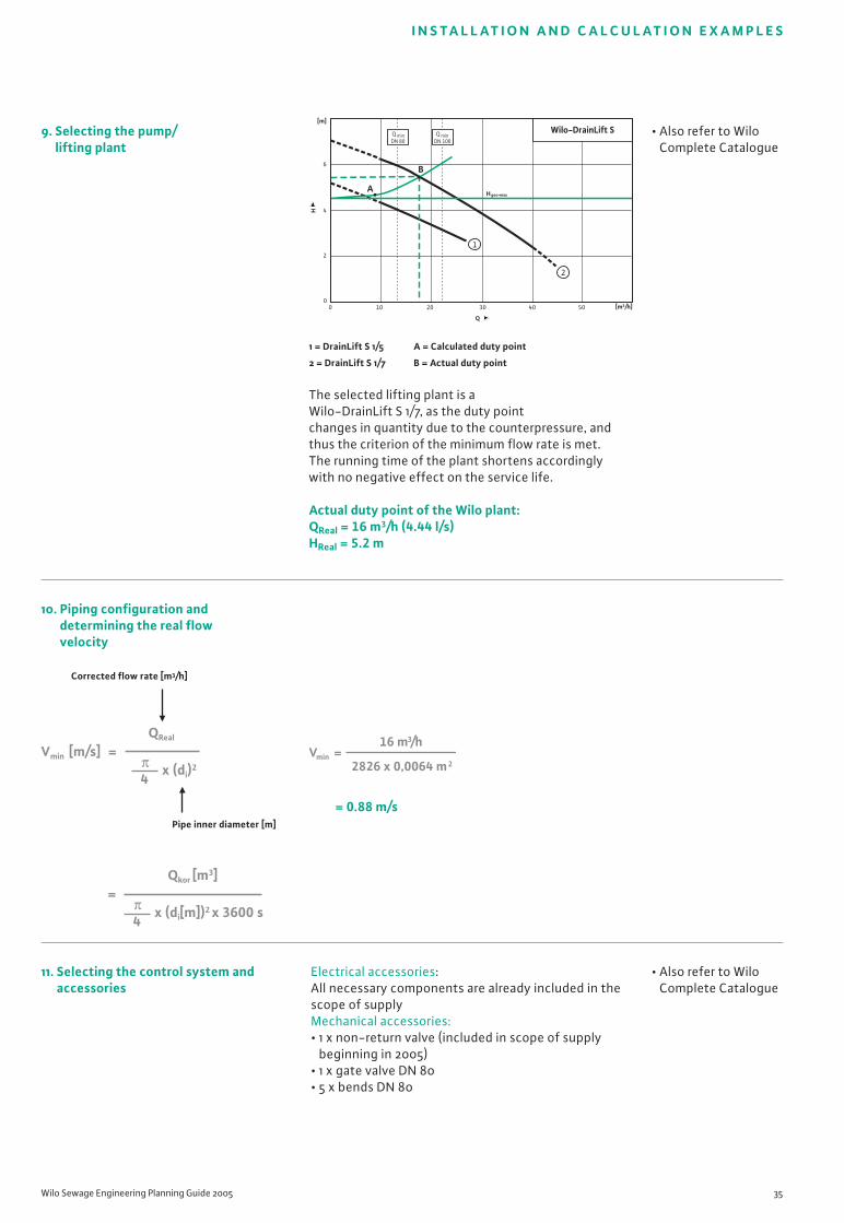
[m3/h]0 10 20 30 40 50H
[m]
0
4
6
2
Q
H geo•maxA
B
2
1
Q minDN 80
Q minDN 100
Wilo-DrainLift S
1 = DrainLift S 1/5 A = Calculated duty point
2 = DrainLift S 1/7 B = Actual duty point
The selected lifting plant is a Wilo-DrainLift S 1/7, as the duty point changes in quantity due to the counterpressure, andthus the criterion of the minimum flow rate is met.The running time of the plant shortens accordinglywith no negative effect on the service life.
Actual duty point of the Wilo plant:QReal = 16 m3/h (4.44 l/s)HReal = 5.2 m
= 0.88 m/s
Electrical accessories: All necessary components are already included in thescope of supplyMechanical accessories:• 1 x non-return valve (included in scope of supply
beginning in 2005)• 1 x gate valve DN 80• 5 x bends DN 80
9. Selecting the pump/lifting plant
10. Piping configuration and determining the real flowvelocity
Corrected flow rate [m3/h]
Pipe inner diameter [m]
11. Selecting the control system andaccessories
• Also refer to Wilo Complete Catalogue
• Also refer to Wilo Complete Catalogue
I N S TA L L AT I O N A N D C A L C U L AT I O N E X A M P L E S
Wilo Sewage Engineering Planning Guide 2005 35
Vmin [m/s] =QReal
x (di)2
4π
=Qkor [m3]
x (di[m])2 x 3600 s4π
Vmin =16 m3/h
2826 x 0,0064 m2
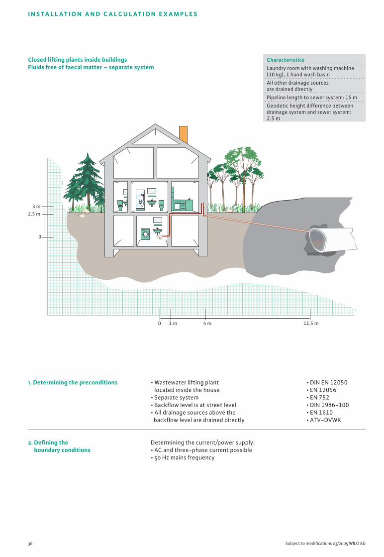
36 Subject to modifications 03/2005 WILO AG
I N S TA L L AT I O N A N D C A L C U L AT I O N E X A M P L E S
• DIN EN 12050• EN 12056• EN 752• DIN 1986-100• EN 1610• ATV-DVWK
Closed lifting plants inside buildingsFluids free of faecal matter – separate system
11.5 m0 1 m 4 m
3 m2.5 m
0
1. Determining the preconditions
2. Defining the boundary conditions
• Wastewater lifting plant located inside the house
• Separate system• Backflow level is at street level• All drainage sources above the
backflow level are drained directly
Determining the current/power supply:• AC and three-phase current possible• 50 Hz mains frequency
CharacteristicsLaundry room with washing machine (10 kg), 1 hand wash basin
All other drainage sourcesare drained directly
Pipeline length to sewer system: 15 m
Geodetic height difference betweendrainage system and sewer system:2.5 m
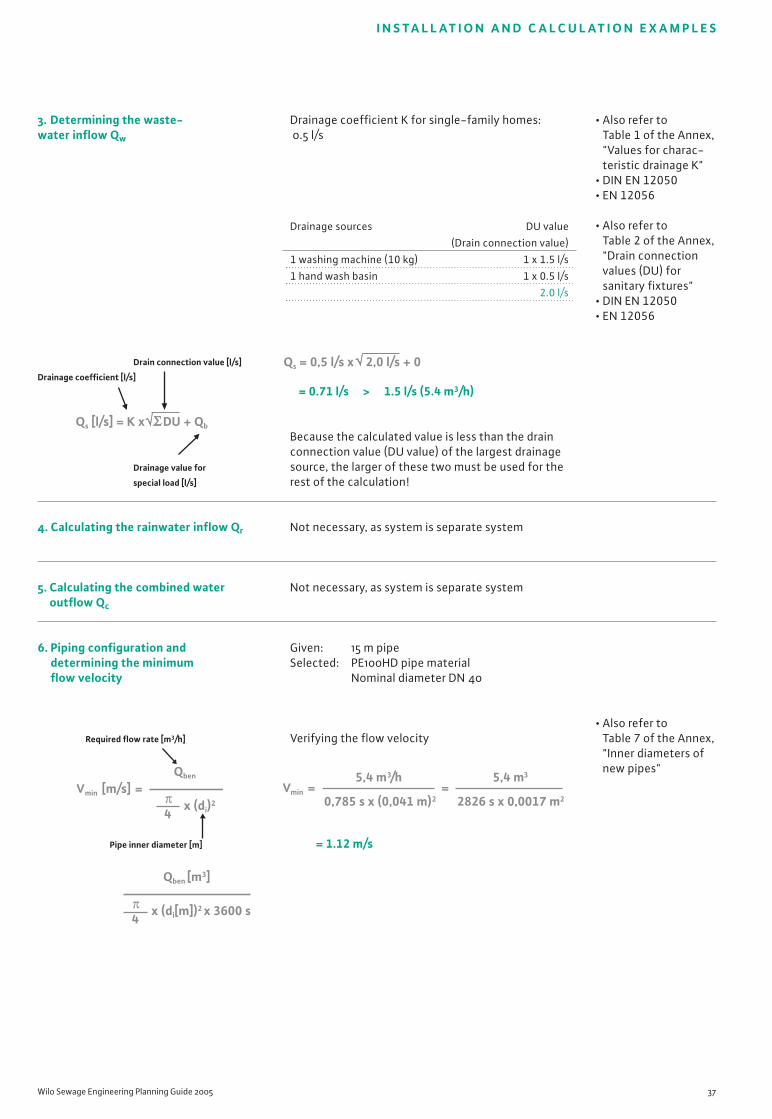
I N S TA L L AT I O N A N D C A L C U L AT I O N E X A M P L E S
Wilo Sewage Engineering Planning Guide 2005 37
3. Determining the waste-water inflow Qw
Drain connection value [l/s]
Drainage coefficient [l/s]
Drainage value for
special load [l/s]
4. Calculating the rainwater inflow Qr
5. Calculating the combined wateroutflow Qc
6. Piping configuration and determining the minimum flow velocity
Required flow rate [m3/h]
Pipe inner diameter [m]
Drainage coefficient K for single-family homes:0.5 l/s
= 0.71 l/s > 1.5 l/s (5.4 m3/h)
Because the calculated value is less than the drainconnection value (DU value) of the largest drainagesource, the larger of these two must be used for therest of the calculation!
Not necessary, as system is separate system
Not necessary, as system is separate system
Given: 15 m pipeSelected: PE100HD pipe material
Nominal diameter DN 40
Verifying the flow velocity
= 1.12 m/s
• Also refer to Table 1 of the Annex, "Values for charac-teristic drainage K"
• DIN EN 12050• EN 12056
• Also refer to Table 2 of the Annex, "Drain connectionvalues (DU) forsanitary fixtures"
• DIN EN 12050• EN 12056
• Also refer to Table 7 of the Annex, "Inner diameters ofnew pipes"
Qs [l/s] = K x DU + Qb
Vmin [m/s] =Qben
x (di)2
4π
Qben [m3]
x (di[m])2 x 3600 s4π
Qs = 0,5 l/s x 2,0 l/s + 0
Drainage sources DU value
(Drain connection value)
1 washing machine (10 kg) 1 x 1.5 l/s
1 hand wash basin 1 x 0.5 l/s
2.0 l/s
Vmin = =5,4 m3/h
0,785 s x (0,041 m)2
5,4 m3
2826 s x 0,0017 m2

38 Subject to modifications 03/2005 WILO AG
7. Selecting the required fittings
8. Calculating the required total delivery head
A. Geodetic height difference
Hgeo-max [m] = NN1 - NN0
Height of transfer Height of water level
or pipe bottom [m]
of the backflow loop
in the reversal point [m]
B. Losses in pipelines
HDP [m] = H*DP x L
Pipeline losses Pipeline
acc. to diagram length [m]
C. Losses in fittings
HDF [m] = (HDF1 + HDF2… + HDFn) x H*DP
Losses in Losses in Losses in
fitting 1 fitting 2 pipelines
[m] [m] acc. to diagram
D. Total losses
HTot [m] = Hgeo-max + HDF + HDP
Geodetic height Losses in Losses
difference fittings in pipe-
[m] [m] lines
[m]
6 bends 90° DN 40 � 1.62 m
Hgeo-max = 3.0 m - 0 m
= 3.0 m
According to table for 15 m HDPE pipe, DN 40, new:
H*DP = 3.5 m/100 m
corresponds to 0.035 m/m of pipeline
HDP = 0.035 x 15 m
= 0.53 m
HDF = (1.62 m) x 0.035
= 0.06 m
HTot = 3.0 m + 0.06 m + 0.053 m
= 3.59 m
Calculated duty point (minimum value):Qmax = 5.4 m3/h (1.5 l/s)Htot = 3.59 m
• Also refer to Table 9 of theAnnex, "Losses in fittings"
• DIN EN 12050-1• DIN 1988-T3
• Also refer to Table 6 of theAnnex, "Pressure drops relative to flowrates of plasticpipelines"
• Also refer to Table 9 of theAnnex, "Losses in fittings"
• DIN EN 12050-1• DIN 1988-T3
I N S TA L L AT I O N A N D C A L C U L AT I O N E X A M P L E S

Wilo Sewage Engineering Planning Guide 2005 39
0 0 1 2 3 4 5 6 7 8
1
2
3
4
5
6
7
m[H
]
Q [m3/h]
Wilo-Drain TMP
H
40/8
A
B32·0,5.1
H geo·max
A = Calculated duty point
B = Actual duty point
The selected lifting plant is a Wilo-DrainLift TMP 40/8
Actual duty point of the Wilo plant:QReal = 7.2 m3/h (2.0 l/s)HReal = 4.2 m
= 1.5 m/s
Electrical accessories:All necessary components are already included inscope of supply• Mini alarm switchgear or
Wilo-Alarm Control 1 optionalMechanical accessories:• 6 x 90° bends
9. Selecting the pump/lifting plant
10. Piping configuration and determining the real flowvelocity
Corrected flow rate [m3/h]
Pipe inner diameter [m]
11. Selecting the control system andaccessories
• Also refer to Wilo Complete Catalogue
• Also refer to Wilo Complete Catalogue
I N S TA L L AT I O N A N D C A L C U L AT I O N E X A M P L E S
Vmin [m/s] =QReal
x (di)2
4π
=Qkor [m3]
x (di[m])2 x 3600 s4π
Vmin =7,2 m3
2826 s x 0,0017 m2
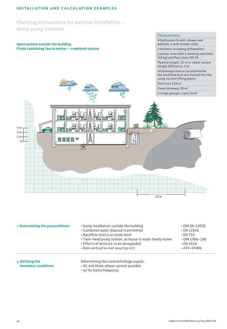
25 m
4 m3 m1 m
0
40 Subject to modifications 03/2005 WILO AG
I N S TA L L AT I O N A N D C A L C U L AT I O N E X A M P L E S
• DIN EN 12050• EN 12056• EN 752• DIN 1986-100• EN 1610• ATV-DVWK
Planning instructions for exterior installation – sump pump stations
Open system outside the buildingFluids containing faecal matter – combined system
1. Determining the preconditions
2. Defining the boundary conditions
• Sump installation outside the building• Combined water disposal is permitted• Backflow level is at street level• Twin-head pump station, as house is multi-family home• Effects of wind are to be disregarded• Rain vertical to roof area (150 m2)
Determining the current/voltage supply:• AC and three-phase current possible• 50 Hz mains frequency
Characteristics8 bathrooms (4 with shower and bathtub, 4 with shower only)
4 kitchens including dishwashers
Laundry room with 4 washing machines(10 kg) and floor drain DN 50
Pipeline length: 25 m to sewer systemHeight difference: 4 m
All drainage sources located belowthe backflow level are drained into thesump via mini lifting plants
Roof area 150 m2
Paved driveway 30 m2
4 single garages, each 10 m2
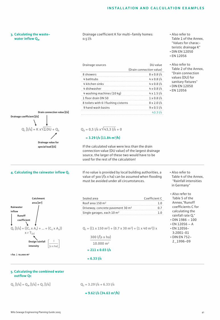
Wilo Sewage Engineering Planning Guide 2005 41
I N S TA L L AT I O N A N D C A L C U L AT I O N E X A M P L E S
3. Calculating the waste-water inflow Qw
Drain connection value [l/s]
Drainage coefficient [l/s]
Drainage value for
special load [l/s]
4. Calculating the rainwater inflow Qr
Catchment
area [m2]
Rainwater
inflow
Runoff
coefficient
Qr [l/s] = ((C1 x A1) + … + (Cz x Az)) x r T(n)
Design rainfall
intensity
1 ha � 10,000 m2
5. Calculating the combined wateroutflow Qc
Qc [l/s] = Qw [l/s] + Qr [l/s]
Drainage coefficient K for multi-family homes: 0.5 l/s
= 3.29 l/s (11.84 m3/h)
If the calculated value were less than the drainconnection value (DU value) of the largest drainagesource, the larger of these two would have to beused for the rest of the calculation!
If no value is provided by local building authorities, avalue of 300 l/(s x ha) can be assumed when floodingmust be avoided under all circumstances.
Qr = ((1 x 150 m2) + (0.7 x 30 m2) + (1 x 40 m2)) x
= 211 x 0.03 l/s
= 6.33 l/s
Qc = 3.29 l/s + 6.33 l/s
= 9.62 l/s (34.63 m3/h)
• Also refer to Table 1 of the Annex, "Values for charac-teristic drainage K"
• DIN EN 12050• EN 12056
• Also refer to Table 2 of the Annex, "Drain connectionvalues (DU) forsanitary fixtures"
• DIN EN 12050• EN 12056
• Also refer to Table 4 of the Annex, "Rainfall intensitiesin Germany"
• Also refer to Table 5 of theAnnex,"Runoffcoefficients C forcalculating therainfall rate Qr"
• DIN 1986 – 100• EN 12056 – A• EN 12056-
3:2001-01• DIN EN 752-
2_1996-09
Qs [l/s] = K x DU + Qb Qs = 0,5 l/s x 43,3 l/s + 0
Drainage sources DU value
(Drain connection value)
8 showers 8 x 0.8 l/s
4 bathtubs 4 x 0.8 l/s
4 kitchen sinks 4 x 0.8 l/s
4 dishwasher 4 x 0.8 l/s
4 washing machines (10 kg) 4 x 1.5 l/s
1 floor drain DN 50 1 x 0.8 l/s
8 toilets with 6 l flushing cisterns 8 x 2.0 l/s
9 hand wash basins 9 x 0.5 l/s
43.3 l/s
Sealed area Coefficient C
Roof area 150 m2 1.0
Driveway, concrete pavement 30 m2 0.7
Single garages, each 10 m2 1.0
l
(s x ha)
300 l/(s x ha)
10.000 m2
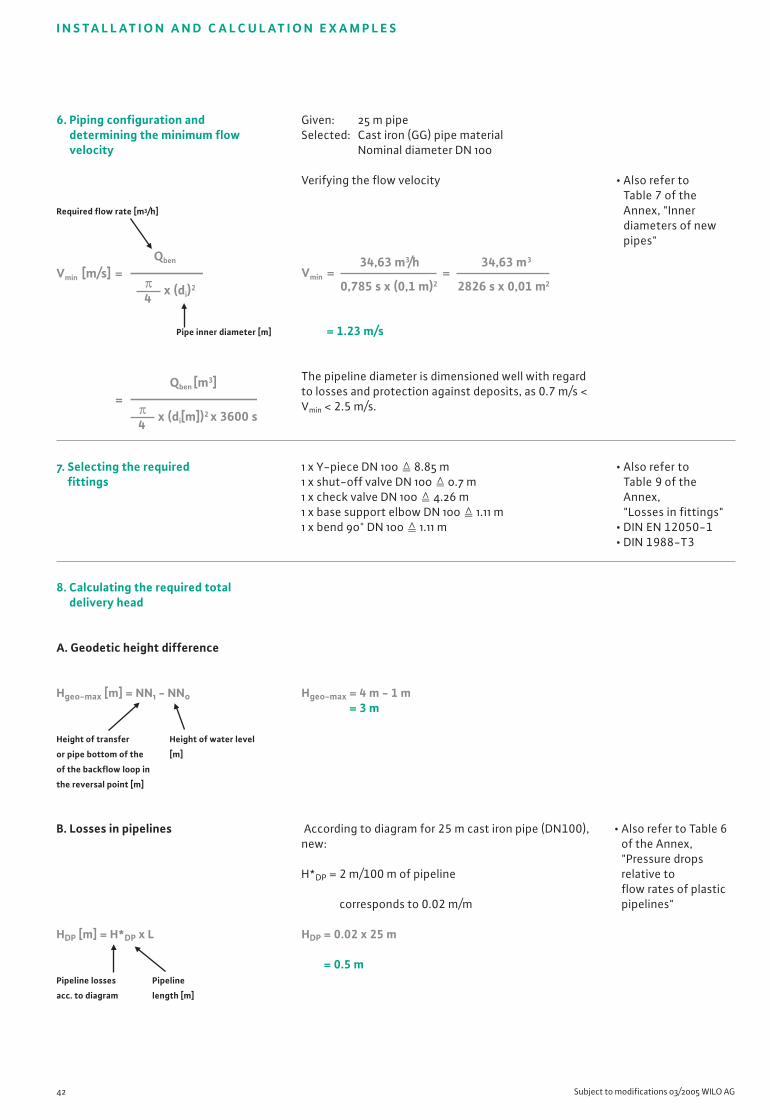
6. Piping configuration and determining the minimum flowvelocity
Required flow rate [m3/h]
Pipe inner diameter [m]
7. Selecting the required fittings
8. Calculating the required total delivery head
A. Geodetic height difference
Hgeo-max [m] = NN1 - NN0
Height of transfer Height of water level
or pipe bottom of the [m]
of the backflow loop in
the reversal point [m]
B. Losses in pipelines
HDP [m] = H*DP x L
Pipeline losses Pipeline
acc. to diagram length [m]
42 Subject to modifications 03/2005 WILO AG
Given: 25 m pipeSelected: Cast iron (GG) pipe material
Nominal diameter DN 100
Verifying the flow velocity
= 1.23 m/s
The pipeline diameter is dimensioned well with regardto losses and protection against deposits, as 0.7 m/s <Vmin < 2.5 m/s.
1 x Y-piece DN 100 � 8.85 m1 x shut-off valve DN 100 � 0.7 m1 x check valve DN 100 � 4.26 m1 x base support elbow DN 100 � 1.11 m1 x bend 90° DN 100 � 1.11 m
Hgeo-max = 4 m - 1 m= 3 m
According to diagram for 25 m cast iron pipe (DN100),new:
H*DP = 2 m/100 m of pipeline
corresponds to 0.02 m/m
HDP = 0.02 x 25 m
= 0.5 m
• Also refer to Table 7 of theAnnex, "Innerdiameters of newpipes"
• Also refer to Table 9 of theAnnex, "Losses in fittings"
• DIN EN 12050-1• DIN 1988-T3
• Also refer to Table 6of the Annex, "Pressure dropsrelative toflow rates of plasticpipelines"
I N S TA L L AT I O N A N D C A L C U L AT I O N E X A M P L E S
Vmin [m/s] =Qben
x (di)2
4π
=Qben [m3]
x (di[m])2 x 3600 s4π
Vmin = =34,63 m3/h
0,785 s x (0,1 m)2
34,63 m3
2826 s x 0,01 m2

Wilo Sewage Engineering Planning Guide 2005 43
I N S TA L L AT I O N A N D C A L C U L AT I O N E X A M P L E S
C. Losses in fittings
HDF [m] = (HDF1 + HDF2… + HDFn) x H*DP
Losses in Losses in Losses in
fitting 1 fitting 2 pipelines
[m] [m] acc. to diagram
D. Total losses
HTot [m] = Hgeo-max + HDF + HDP
Geodetic Losses in Losses
height fittings in pipe-
difference [m] lines [m]
[m]
9. Designing the pump/system
HDF = (8.95 m + 4.26 m + 0.7 m + 1.1 m + 1.1 m) x 0.02
= 0.32 m
HTot = 3 m + 0.5 m + 0.32 m
= 3.82 m
Calculated duty point (minimum value):Qmax = 34.63 m3/h (9.62 l/s)HTot = 3.82 m
• Select an impeller that corresponds to your ownpriorities.
• Reliable and problem-free: Vortex• Cost-effective in operation: single or multi-vane• Here: Vortex is recommended, due to combination
of widely varied fluid components
9 = TP 100 F 155/20
10 = TP 100 F 165/24
11 = TP 100 F 180/27
12 = TP 100 F 190/32
13 = TP 100 F 210/34
A = Calculated duty point
B = Actual duty point
The selected pump is a Wilo-Drain TP 100 F 155/20 (at 3~400 V: 6.1 A).
Actual duty point of the Wilo pump:QReal = 38 m3/h (10.6 l/s)HTot = 4.2 m
• Also refer to Table 9 of theAnnex, "Losses infittings"
• DIN EN 12050-1• DIN 1988-T3
• Also refer to thechapter on "Basic hydraulic concepts andpipelines–Impeller types"
• Also refer to Wilo Complete Catalogue
Q[lgpm]
H
000 5 10
0 100 200 300 400
15 20 25 30 35
2
4
6
8
10
12
14
[l/s]
[m3/h]
H geo-max
xx
Wilo-Drain TP 100F
20 40 60 80 100 120
13
121110
9
[m]
A
B
xx
x

= 0.48 m3
Minimum value calculation:
= 0.79 m
Minimum value calculation:
HSmp-Tot = 0.79 m + 0.15 m + 0.1 m + 1 m
= 2.04 m
44 Subject to modifications 03/2005 WILO AG
10. Configuring the sump
A. Usable volume
Flow rate of the largest pumps [l/s]
Operating cycles [per hour]
B. Sump height (inside)
a. Inlet height depending onthe flow rate
Usable volume Minimum level
of tank [m3] in tank = water
coverage of pump
Tank diameter acc. to
manufacturer's specifi-
cations [m]
b. Total sump height
Height of the inlet pipeline Diameter of the
based on flow rate [m] discharge pipeline [m]
HSmp-Tot = HIn-Q + HIn-DL + HDi-L + HFr
Diameter of the Safety height for
inlet pipeline [m] frost-proof installation [m]
• Also refer to Table 10 of theAnnex, "Operating cyclesper hour of Wilopumps"
• Also refer to WiloComplete Catalogue
I N S TA L L AT I O N A N D C A L C U L AT I O N E X A M P L E S
VNutz [m3] =Z
0,9 x Q VNutz =20 1/h
0,9 x 10,6 l/s
HZu-Q [m] = + HBeh-min
VN-Beh
( x (DBeh)2) 4π
HZu-Q = + 0,34 m0,48 m3
( x (1,5 m)2) 4
= + 0,34 m0,48 m3
(0,785 x 2,25 m2)

Wilo Sewage Engineering Planning Guide 2005 45
I N S TA L L AT I O N A N D C A L C U L AT I O N E X A M P L E S
11. Calculating the switching points
Usable volume of tank [m3]
Inner diameter
of the sump
acc. to manufacturer's specifications [m]
12. Selecting the control system andaccessories
= 0.27 m
• Minimum cut-in point: 0.61 m• Cut-out point: 0.34 m
Electrical accessories:• Wilo-DrainControl PL 2 (control system)• Wilo level sensor 4-20 mA (level measurement)Mechanical accessories for stationary wet sumpinstallation:• 2 x base support elbows including guide,
2 x check valves• 1 x gate valve• 1 x pipe bend 90°• 1 x Y-piece• 2 x chains, 5 m
Wilo-Drain WB is supplied already complete from thefactory
• Also refer to Wilo CompleteCatalogue
• Also refer to thechapter "Additionalplanning guide–Selecting switch-ing devices for submersiblepumps"
HSignal [m] =π4
x (DBeh)2
VN-Beh
( x (1,5 m)2)HSignal = π
4
0,48 m3
HSignal =(0,785 x 2,25 m2)
0,48 m3
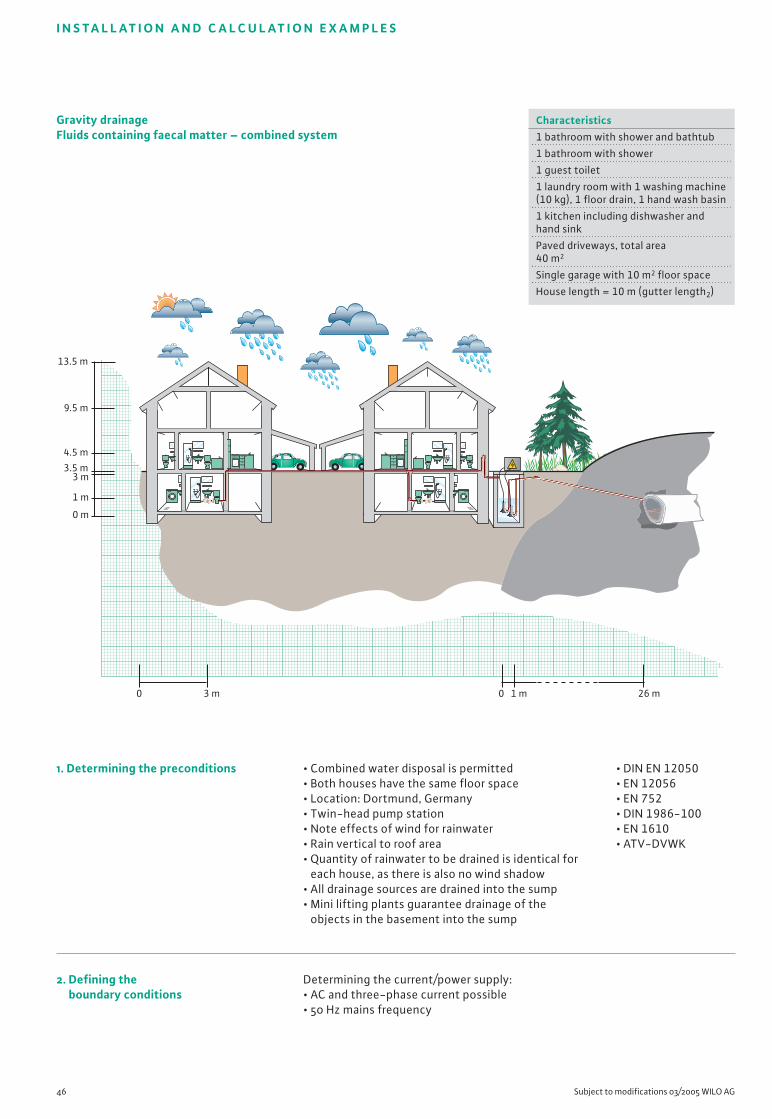
46 Subject to modifications 03/2005 WILO AG
I N S TA L L AT I O N A N D C A L C U L AT I O N E X A M P L E S
• DIN EN 12050• EN 12056• EN 752• DIN 1986-100• EN 1610• ATV-DVWK
Gravity drainageFluids containing faecal matter – combined system
3 m3.5 m
9.5 m
13.5 m
1 m
4.5 m
0 m
26 m1 m03 m0
1. Determining the preconditions
2. Defining the boundary conditions
• Combined water disposal is permitted• Both houses have the same floor space • Location: Dortmund, Germany• Twin-head pump station • Note effects of wind for rainwater• Rain vertical to roof area • Quantity of rainwater to be drained is identical for
each house, as there is also no wind shadow• All drainage sources are drained into the sump• Mini lifting plants guarantee drainage of the
objects in the basement into the sump
Determining the current/power supply:• AC and three-phase current possible• 50 Hz mains frequency
Characteristics1 bathroom with shower and bathtub
1 bathroom with shower
1 guest toilet
1 laundry room with 1 washing machine(10 kg), 1 floor drain, 1 hand wash basin
1 kitchen including dishwasher andhand sink
Paved driveways, total area40 m2
Single garage with 10 m2 floor space
House length = 10 m (gutter length2)
Wilo Sewage Engineering Planning Guide 2005 47
I N S TA L L AT I O N A N D C A L C U L AT I O N E X A M P L E S
3. Calculating the wastewater inflow Qw
Drain connection value [l/s]
Drainage coefficient [l/s]
Drainage value for special
load [l/s]
4. Calculating the rainwater inflow Qr
A. Calculating the roof area
Roof area Horizontal roof depth [m]
ARoof [m2] = LG2 (Dhor + 0.5 x Dvert)
Gutter length2 [m] Vertical roof depth [m]
B. Calculating the wall area
Wall area Gutter length2 [m]
AWall [m2] = 0.5 x (LG2 x HWall)
Wall area [m]
C. Calculating the total catchment areaper roof
Roof area [m2] Wall area [m2]
ATotal [m2] = ARoof + AWall
Drainage coefficient K for residential buildings: 0.5 l/s
Drainage sources DU value
4 showers 4 x 0.8 l/s
2 bathtubs 2 x 0.8 l/s
2 kitchen sinks 2 x 0.8 l/s
2 dishwashers 2 x 0.8 l/s
2 washing machines (10 kg) 2 x 1.5 l/s
2 floor drains DN 50 2 x 0.8 l/s
6 toilets with 6 l flushing cisterns 6 x 2.0 l/s
8 hand wash basins 8 x 0.5 l/s
28.6 l/s
= 2.67 l/s (9.61 m3/h)
ARoof = 10 m (3 m + 0.5 x 4 m)
= 50 m2 per roof section
= 100 m2 roof area per house
AWall = 0.5 x (10 m x 6 m)
= 30 m2
For each house:
ATotal = 100 m2 + 30 m2 = 130 m2
Total quantity130 m2 x 2 = 260 m2
• Also refer to Table 1 of theAnnex, "Values for charac-teristic drainage K"
• DIN EN 12050• EN 12056
• Also refer to Table 2 of theAnnex, "Drainconnection values(DU) for sanitaryfixtures"
• DIN EN 12050• EN 12056
• Also refer to thechapter on "Basic concepts–roof area"
• EN 12056-3
Qs = 0,5 l/s x 28,6 l/s + 0Qs [l/s] = K x DU + Qb
48 Subject to modifications 03/2005 WILO AG
I N S TA L L AT I O N A N D C A L C U L AT I O N E X A M P L E S
D. Calculating the rainwater inflow
Catchment area [m2]
Rainwater
inflow
Runoff coefficient
Qr [l/s] = ((C1 x A1) + … + (Cz x Az)) x r T(n)
Design rainfall
intensity
1 ha � 10,000 m2
5. Calculating thecombined water outflow Qc
Qc [l/s] = Qw [l/s] + Qr [l/s]
6. Piping configuration and determining the minimumflow velocity
Required flow rate [m3/h]
Pipe inner diameter [m]
7. Selecting the required fittings
Location: Dortmund, Germany
Sealed area Coefficient C
Roof area 260 m2 1.0
Driveway, concrete pavement 40 m2 0.7
2 garages, each 10 m2 1.0
Qr = ((1 x 260 m2) + (0.6 x 40 m2) + (1 x 20 m2)) x
= 8.42 l/s
Qc = 2.67 l/s + 8.42 l/s
= 11.09 l/s (39.92 m3/h)
Given: 29 m pipeSelected: HDPE pipe material
Nominal diameter DN 80
Verifying the flow velocity
= 2.21 m/s
The pipeline diameter is dimensioned sufficientlywith regard to losses and protection against deposits,as 0.7 m/s < Vmin < 2.5 m/s. This is also adequate tocarry heavier particles of the drainage water.
1 x Y-piece DN 80 � 6.58 m2 x shut-off valves DN 80 � 1.12 m2 x check valves DN 80 � 6.6 m2 x base support elbows DN 80 � 1.58 m1 x bend 45° DN 80 � 0.79 m
• Also refer to Table 4 of theAnnex, "Rainfall intensi-ties in Germany"
• Also refer to"Determining thepreconditions"
• DIN 1986-100• ATV-DVWK A 118
• Also refer to Table 7 of theAnnex, "Inner diameters ofnew pipes"
• Also refer to Table 9 of theAnnex, "Losses in fittings"
• DIN EN 12050-1• DIN 1988-T3
277 l/(s x ha)
10.000 m2l
(s x ha)
Vmin [m/s] =Qben
x (di)2
4π
=Qben [m3]
x (di[m])2 x 3600 s4π
Vmin = =39,9 m3/h
0,785 s x (0,08 m)2
39,9 m3
2826 s x 0,0064 m2
Wilo Sewage Engineering Planning Guide 2005 49
I N S TA L L AT I O N A N D C A L C U L AT I O N E X A M P L E S
8. Calculating the required total delivery head
A. Geodetic height difference
Hgeo-max [m] = NN1 - NN0
Height of transfer Height of
or pipe bottom of water level [m]
backflow loop in
reversal point [m]
B. Losses in pipelines
HDP [m] = H*DP x L
Pipeline losses Pipeline
acc. to diagram length [m]
C. Losses in fittings
HDF [m] = (HDF1 + HDF2… + HDFn) x H*DP
Losses in Losses in Losses in
fitting 1 fitting 2 pipeline
[m] [m] acc. to diagram
D. Total losses
HTot [m] = Hgeo-max + HDF + HDP
Geodetic height Losses in Losses
difference [m] fittings in pipe-
[m] lines [m]
Hgeo-max = 3 m - 1m
= 2 m
According to diagram for 29 m cast iron pipe, new:
H*DP = 7.5 m/100 m pipeline
corresponds to 0.075 m/m
HDP = 0.075 x 29 m
= 2.18 m
HDF = (6.58 m + 1.12 m + 6.6 m + 1.58 m + 0.79 m) x 0.02
= 0.33 m
HTot = 2 m + 2.18 m + 0.33 m
= 4.51 m
Calculated duty point (minimum value):Qmax = 39.92 m3/h (11.09 l/s)HTot 4.5 m
• Also refer to Table 8 of the Annex,"Pipe friction lossesand correctionfactors"
• Also refer to Table 9 of the Annex,"Losses in fittings"
• DIN EN 12050-1• DIN 1988-T3

50 Subject to modifications 03/2005 WILO AG
I N S TA L L AT I O N A N D C A L C U L AT I O N E X A M P L E S
9. Selecting the pump
10. Configuring the sump
A. Usable volume
Flow rate of the largest pumps [l/s]
Operating cycles [per hour]
• Select an impeller that corresponds to your ownpriorities.
• Reliable and problem-free: Vortex• Cost-effective in operation: single or multi-vane
1 = TP 65 E 114/11
2 = TP 65 E 122/15
3 = TP 65 E 132/22
A = Calculated duty point
B = Actual duty point
The selected pump is a Wilo-Drain TP 65 E 114/11 (at 3~400 V: 3.2 A).
Actual duty point of the Wilo pump:QReal = 48 m3/h (13.3 l/s)HReal = 4.6 m
= 0.6 m3
• Also refer to thechapter on "Basic hydraulicconcepts andpipelines –Impeller types –Advantages of use"
• Also refer to Wilo CompleteCatalogue
• ATV-DVWK A 134
• Also refer to Table 10 of theAnnex, "Operatingcycles per hour ofWilo pumps"
VNutz [m3] =Z
0,9 x Q VNutz =20 1/h
0,9 x 13,3 l/s
[l/s]
0 8 24 3 2 40 48 5616
20
16
12
8
4
0 [m3/h]
Q
0 5 10 15
Wilo-DrainTP 65 E
H
[m]
H geo-max 213
A B
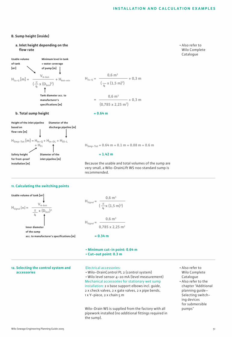
Wilo Sewage Engineering Planning Guide 2005 51
I N S TA L L AT I O N A N D C A L C U L AT I O N E X A M P L E S
B. Sump height (inside)
a. Inlet height depending on the flow rate
Usable volume Minimum level in tank
of tank = water coverage
[m3] of pump [m]
Tank diameter acc. to
manufacturer's
specifications [m]
b. Total sump height
Height of the inlet pipeline Diameter of the
based on discharge pipeline [m]
flow rate [m]
HSmp-Tot [m] = HIn-Q + HIn-DL + HDi-L+ HFr
Safety height Diameter of the
for frost-proof inlet pipeline [m]
installation [m]
11. Calculating the switching points
Usable volume of tank [m3]
Inner diameter
of the sump
acc. to manufacturer's specifications [m]
12. Selecting the control system andaccessories
= 0.64 m
HSmp-Tot = 0.64 m + 0.1 m + 0.08 m + 0.6 m
= 1.42 m
Because the usable and total volumes of the sump arevery small, a Wilo-DrainLift WS 1100 standard sump isrecommended.
= 0.34 m
• Minimum cut-in point: 0.64 m• Cut-out point: 0.3 m
Electrical accessories:• Wilo-DrainControl PL 2 (control system)• Wilo level sensor 4-20 mA (level measurement)Mechanical accessories for stationary wet sumpinstallation: 2 x base support elbows incl. guide, 2 x check valves, 2 x gate valves, 2 x pipe bends, 1 x Y-piece, 2 x chain 5 m
Wilo-Drain WS is supplied from the factory with allpipework installed (no additional fittings required inthe sump).
• Also refer to Wilo CompleteCatalogue
• Also refer to Wilo CompleteCatalogue
• Also refer to thechapter "Additionalplanning guide–Selecting switch-ing devices for submersiblepumps"
HSignal [m] =π4
x (DBeh)2
VN-Beh
HZu-Q = + 0,3 m0,6 m3
( x (1,5 m)2) 4
= + 0,3 m0,6 m3
(0,785 x 2,25 m2)
HZu-Q [m] = + HBeh-min
VN-Beh
( x (DBeh)2) 4π
HSignal = π4( x (1,5 m)2)
0,6 m3
HSignal =0,785 x 2,25 m2
0,6 m3

52 Subject to modifications 03/2005 WILO AG
I N S TA L L AT I O N A N D C A L C U L AT I O N E X A M P L E S
• DIN EN 12050• EN 12056• EN 752• DIN 1986-100• EN 1610• ATV-DVWK
Exterior installation outside the buildingFluids containing faecal matter – separate system
14 m1 m0
6 m
1 m
0
1. Determining the preconditions
2. Defining the boundary conditions
• 3 single-family terraced houses• Separate system• Backflow level is at street level• Sump installation outside the building• Twin-head pump system• All drainage sources located below the backflow
level are drained into the sump using mini liftingplants
Determining the current/power supply:• AC and three-phase current possible• 50 Hz mains frequency
Characteristics6 bathrooms(3 with shower and 3 with bathtub)
3 kitchens including dishwashers
3 laundry rooms with 3 washing machines (10 kg) and 3 floor drains DN 50
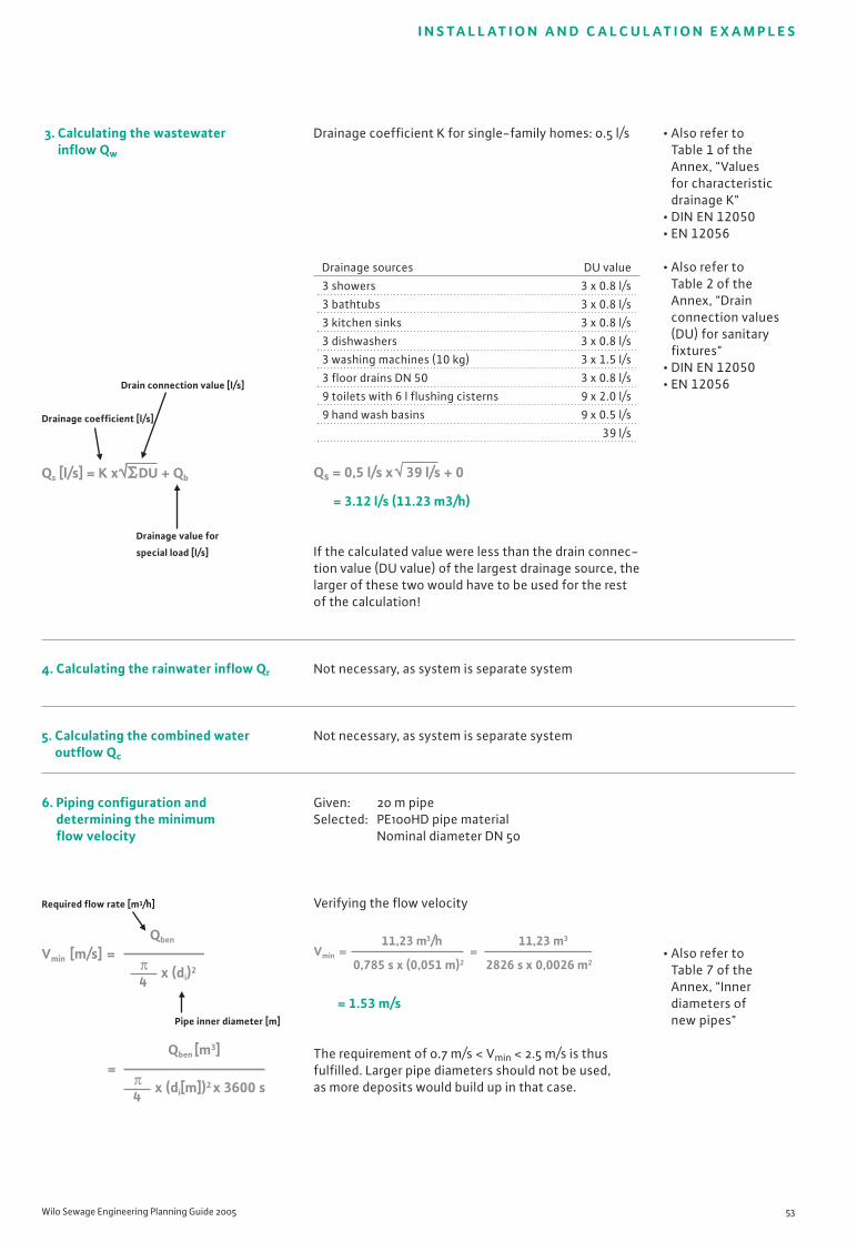
Wilo Sewage Engineering Planning Guide 2005 53
I N S TA L L AT I O N A N D C A L C U L AT I O N E X A M P L E S
3. Calculating the wastewater inflow Qw
Drain connection value [l/s]
Drainage coefficient [l/s]
Drainage value for
special load [l/s]
4. Calculating the rainwater inflow Qr
5. Calculating the combined wateroutflow Qc
6. Piping configuration and determining the minimum flow velocity
Required flow rate [m3/h]
Pipe inner diameter [m]
Drainage coefficient K for single-family homes: 0.5 l/s
Drainage sources DU value
3 showers 3 x 0.8 l/s
3 bathtubs 3 x 0.8 l/s
3 kitchen sinks 3 x 0.8 l/s
3 dishwashers 3 x 0.8 l/s
3 washing machines (10 kg) 3 x 1.5 l/s
3 floor drains DN 50 3 x 0.8 l/s
9 toilets with 6 l flushing cisterns 9 x 2.0 l/s
9 hand wash basins 9 x 0.5 l/s
39 l/s
= 3.12 l/s (11.23 m3/h)
If the calculated value were less than the drain connec-tion value (DU value) of the largest drainage source, thelarger of these two would have to be used for the restof the calculation!
Not necessary, as system is separate system
Not necessary, as system is separate system
Given: 20 m pipeSelected: PE100HD pipe material
Nominal diameter DN 50
Verifying the flow velocity
= 1.53 m/s
The requirement of 0.7 m/s < Vmin < 2.5 m/s is thusfulfilled. Larger pipe diameters should not be used,as more deposits would build up in that case.
• Also refer to Table 1 of theAnnex, "Values for characteristicdrainage K"
• DIN EN 12050• EN 12056
• Also refer to Table 2 of theAnnex, "Drainconnection values(DU) for sanitaryfixtures"
• DIN EN 12050• EN 12056
• Also refer to Table 7 of theAnnex, "Innerdiameters of new pipes"
Qs [l/s] = K x DU + Qb Qs = 0,5 l/s x 39 l/s + 0
Vmin [m/s] =Qben
x (di)2
4π
=Qben [m3]
x (di[m])2 x 3600 s4π
Vmin = =11,23 m3/h
0,785 s x (0,051 m)2
11,23 m3
2826 s x 0,0026 m2
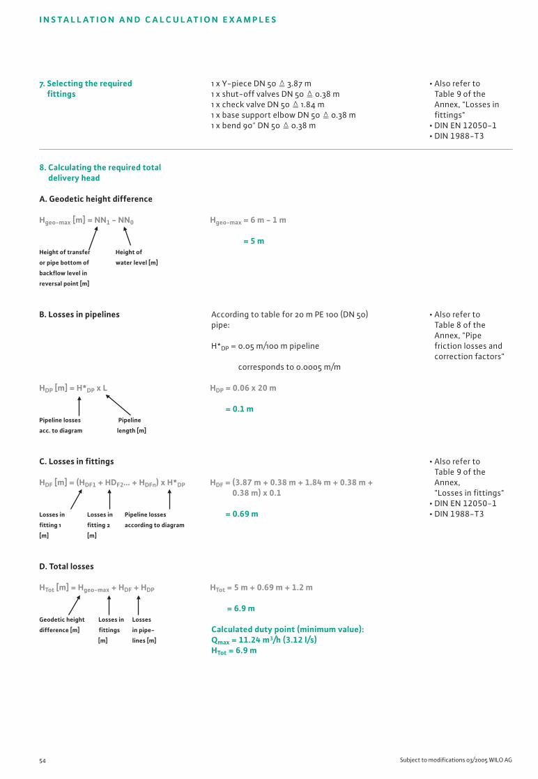
54 Subject to modifications 03/2005 WILO AG
I N S TA L L AT I O N A N D C A L C U L AT I O N E X A M P L E S
7. Selecting the required fittings
8. Calculating the required totaldelivery head
A. Geodetic height difference
Hgeo-max [m] = NN1 - NN0
Height of transfer Height of
or pipe bottom of water level [m]
backflow level in
reversal point [m]
B. Losses in pipelines
HDP [m] = H*DP x L
Pipeline losses Pipeline
acc. to diagram length [m]
C. Losses in fittings
HDF [m] = (HDF1 + HDF2… + HDFn) x H*DP
Losses in Losses in Pipeline losses
fitting 1 fitting 2 according to diagram
[m] [m]
D. Total losses
HTot [m] = Hgeo-max + HDF + HDP
Geodetic height Losses in Losses
difference [m] fittings in pipe-
[m] lines [m]
1 x Y-piece DN 50 � 3.87 m1 x shut-off valves DN 50 � 0.38 m1 x check valve DN 50 � 1.84 m1 x base support elbow DN 50 � 0.38 m1 x bend 90° DN 50 � 0.38 m
Hgeo-max = 6 m - 1 m
= 5 m
According to table for 20 m PE 100 (DN 50)pipe:
H*DP = 0.05 m/100 m pipeline
corresponds to 0.0005 m/m
HDP = 0.06 x 20 m
= 0.1 m
HDF = (3.87 m + 0.38 m + 1.84 m + 0.38 m + 0.38 m) x 0.1
= 0.69 m
HTot = 5 m + 0.69 m + 1.2 m
= 6.9 m
Calculated duty point (minimum value):Qmax = 11.24 m3/h (3.12 l/s)HTot = 6.9 m
• Also refer to Table 9 of theAnnex, "Losses infittings"
• DIN EN 12050-1• DIN 1988-T3
• Also refer to Table 8 of theAnnex, "Pipefriction losses andcorrection factors"
• Also refer to Table 9 of theAnnex, "Losses in fittings"
• DIN EN 12050-1• DIN 1988-T3

Wilo Sewage Engineering Planning Guide 2005 55
I N S TA L L AT I O N A N D C A L C U L AT I O N E X A M P L E S
9. Selecting thepump/lifting plant
10. Configuring the sump
A. Usable volume
Flow rate of the largest pumps [l/s]
Operating cycles [per hour]
• Select an impeller that corresponds to your ownpriorities.
• Reliable and problem-free: Vortex• Cost-effective in operation: single or multi-vane• Alternative: pump with macerator
• Here: pump with macerator recommended
1 = MTS 40 E 17.13/11
2 = MTS 40 E 20.14/13
3 = MTS 40 E 23.15/15
4 = MTS 40 E 32.14/21
5 = MTS 40 E 35.15/23
6 = MTS 40 E 35.15/23
A = Calculated duty point
B = Actual duty point
The selected pump is a Wilo-Drain MTS 40 E 20.14/13 (at 3~400 V: 2.8 A).
Actual duty point of the Wilo pump:QReal = 11.4 m3/h (3.2 l/s)HReal = 7.8 m
= 0.14 m3
• Also refer to thechapter on "Basichydraulic conceptsand pipelines–Impeller types"
• Also refer to Wilo CompleteCatalogue
• ATV-DVWK A 134
• Also refer to Table 10 of theAnnex, "Operatingcycles per hour ofWilo pumps"VNutz [m3] =
Z0,9 x Q
[m3/h]Q
8
20
16
4
12
H
24
28
32
36Wilo-Drain
MTS 40 E
56
3210
0 2 4 6 8 10 12 1614 18
[m]
Hgeo-max4
BA
VNutz =20 1/h
0,9 x 3,2 l/s

56 Subject to modifications 03/2005 WILO AG
I N S TA L L AT I O N A N D C A L C U L AT I O N E X A M P L E S
B. Sump height (inside)
a. Inlet height depending on the flow rate
Usable volume Minimum water level
of tank [m3] in tank = water
coverage of
pump [m]
Tank diameter acc. to manu-
facturer's specifications [m]
b. Total sump height
Height of the Diameter of the
inlet pipeline discharge pipeline [m]
based on
flow rate [m]
HSmp-Tot [m] = HIn-Q + HIn-DL + HDi-L +HFr
Safety height Diameter of the
for frost-proof inlet pipeline [m]
installation [m]
12. Selecting the control systemand accessories
= 0.5 m
HSmp-Tot = 0.5 m + 0.05 m + 0.05 m + 1 m
= 1.6 m
Because the usable and total volumes of the sump arevery small, a Wilo-DrainLift WS 1100 standard sump isrecommended.
Electrical accessories:• Wilo-DrainControl PL 2 (control system)• Wilo level sensor 4-20 mA (level measurement)Mechanical accessories for stationary wet sumpinstallation:• 2 x base support elbows incl. guide• 2 x check valves• 1 x gate valve• 1 x pipe bend 90°• 1 x Y-piece• 2 x chains, 5 m
Wilo-Drain WS is supplied from the factory with allpipework installed (no additional fittings required inthe sump).
• Also refer to Wilo CompleteCatalogue
• Also refer to Wilo CompleteCatalogue
• Also refer to thechapter "Additionalplanning guide–Selecting switch-ing devices for submersiblepumps"
HZu-Q = + 0,245 m0,14 m3
( x (0,84 m)2) π4
HZu-Q [m] = + HBeh-min
VN-Beh
( x (DBeh)2) 4π
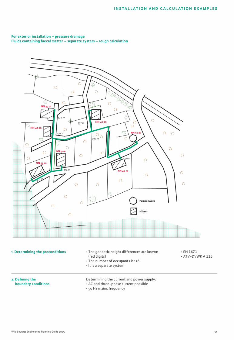
Wilo Sewage Engineering Planning Guide 2005 57
I N S TA L L AT I O N A N D C A L C U L AT I O N E X A M P L E S
• EN 1671• ATV-DVWK A 116
For exterior installation – pressure drainageFluids containing faecal matter – separate system – rough calculation
NN 40 m
NN 50 m
NN 48 m
NN 51 m
NN 47 m
NN 40 m
NN 55 m
579 m
474 m
732 m
70 m
337 m
200 m
769 m
Pumpenwerk
Häuser
1. Determining the preconditions
2. Defining the boundary conditions
• The geodetic height differences are known (red digits)
• The number of occupants is 126• It is a separate system
Determining the current and power supply:• AC and three-phase current possible• 50 Hz mains frequency

58 Subject to modifications 03/2005 WILO AG
I N S TA L L AT I O N A N D C A L C U L AT I O N E X A M P L E S
3. Calculating the wastewater inflow Qw
Formula in accordance with DIN EN 1671
Consumer value [l/s]
Qmax [l/h] = Pers. x 0.005 l/s x 1.5
Number of persons Safety factor
Average hours of pump running time
per day (experience value)
4. Calculating the rainwater inflow Qr
5. Calculating the combined wateroutflow Qc
6. Piping configuration and determining theminimum flow velocity
Required flow rate [m3/h]
Pipe inner diameter [m]
126 persons in 6 residential buildings (21 persons per building)
= 1512 l/h (~1.5 m3/h = 0.42 l/s)
In the following, the calculation example is calculatedin accordance with the experience values. Thus, thecalculation is realistic based on the experience values,but it does not conform to DIN EN 1671.
Not necessary, as system is separate system
Not necessary, as system is separate system
Given: 769 m max. pipeline lengthsSelected: HDPE, nominal diameter DN 50
Verifying the flow velocity
= 0.18 m/s
The flow velocity is not sufficient to avoid deposits.This must be verified again after selecting the pump.
• DIN EN 1671
• Wilo note:Measurementshave yieldedaverage values of80–90 l. Experi-ence has shownthat a value of120 l per occupantand day, includingsafety factors, isrealistic whencalculating thepump system.
• Also refer to Table 7 of theAnnex, "Innerdiameters of newpipes"
Q max [l/h] =Pers. x 120 l
10 hQ max =
126 Pers x 120 l
10 h
Vmin [m/s] =Qben
x (di)2
4π
=Qben [m3]
x (di[m])2 x 3600 s4π
Vmin [m/s] =1,5 m3/h
0,785 s x (0,051 m)2
=1,5 m3
2826 s x 0,003 m2

Wilo Sewage Engineering Planning Guide 2005 59
I N S TA L L AT I O N A N D C A L C U L AT I O N E X A M P L E S
7. Selecting the required fittings
8. Calculating the required total deliv-ery head
A. Geodetic height difference
Hgeo-max [m] = NN1 - NN0
Height of transfer Height of water level
or pipe bottom of [m]
backflow level in
reversal point [m]
B. Losses in pipelines
Pipeline correction value
HDP [m] = H*DP x L x C
Pipeline losses Pipeline
acc. to diagram length [m]
C. Losses in fittings
Correction factor
(see stainless steel
components)
HDF [m] = (HDF1 + HDF2… + HDFn) x H*DP x HC
Losses in Losses in Losses in
fitting 1 fitting 2 pipelines
[m] [m] acc. to diagram
2 bends 90° DN 50 � 0.76 m1 x check valve DN 50 � 1.84 m1 gate valve DN 50 � 0.38 m
Hgeo-max = 55 m - 50 m
= 5 m
According to diagram for 769 m cast iron pipe (DN 50), new:
H*DP = 4 m/100 m pipeline
corresponds to 0.04 m/m
HDP = 0.04 x 769 m x 0.007
= 0.22 m
HDF = (0.76 m + 1.84 m + 0.38 m) x 0.02 x 0.8
= 2.98 m x 0.02 x 0.8
= 0.05 m
• Also refer to Table 9 of theAnnex, "Losses infittings"
• DIN EN 12050-1• DIN 1988-T3
• Also refer to Table 8 of theAnnex, "Pipefriction losses andcorrection factors"
• Also refer to Table 9 of theAnnex, "Losses infittings"
• DIN EN 12050-1• DIN 1988-T3

60 Subject to modifications 03/2005 WILO AG
I N S TA L L AT I O N A N D C A L C U L AT I O N E X A M P L E S
D. Total losses
HTot [m] = Hgeo-max + HDF + HDP
Geodetic height Losses in Losses
difference [m] fittings in pipe-
[m] lines [m]
9. Selecting thepump/lifting plant
HTot = 5 m + 0.05 m + 0.22 m
= 5.27 m
Calculated duty point (minimum value):Qmax = 1.5 m3/h (0.42 l/s)HTot = 5.27 m
A = Calculated duty point
B = Actual duty point
Parallel operation of pumps is to be excluded in thissystem.
Should parallel operation of pumps occur, refer to thechapter on "Basic hydraulic concepts–Parallel connec-tion"
The selected pump is a Wilo-Drain MTS 40/27 F (at 3~400 V: 3.0 A).
Actual duty point of the Wilo pump:QReal = 8.1 m3/h (2.25 l/s)HReal = 18.2 m
Due to changed pump capacity with regard to therequired duty point, only the required operating time ofthe pump is reduced, which has a positive effect on thelifetime of the pump.
• Also refer to thechapter on "Basichydraulic con-cepts–Impellertypes"
• Also refer to Table 11 of theAnnex, "Sumppump stations inparallel operation"
2
4
0
6
10
12
14
16
18
20
22
24
26
8
0 2 4 6 8 10 12 14
Wilo-DrainMTS 40/27
H
[m3/h]Q
[m]
H geo-maxA
B
10 20 30 40 50 60 70 80 90 100
Number of the sump pump stations in the pressure drainage system
Ope
rati
ng t
ime
[s]
1000
700
500
400
300
200
100
70
50
40
30
20
10
2
3
45 6 7 8 9 10 12 14 16
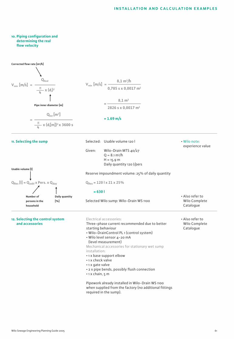
Wilo Sewage Engineering Planning Guide 2005 61
I N S TA L L AT I O N A N D C A L C U L AT I O N E X A M P L E S
10. Piping configuration and determining the realflow velocity
Corrected flow rate [m3/h]
Pipe inner diameter [m]
11. Selecting the sump
Usable volume [l]
QRes [l] = Qusbl x Pers. x Qday
Number of Daily quantity
persons in the [%]
household
12. Selecting the control systemand accessories
= 1.69 m/s
Selected: Usable volume 120 l
Given: Wilo-Drain MTS 40/27Q = 8.1 m3/hH = 15.9 mDaily quantity 120 l/pers
Reserve impoundment volume: 25% of daily quantity
QRes = 120 l x 21 x 25%
= 630 l
Selected Wilo sump: Wilo-Drain WS 1100
Electrical accessories:Three-phase current recommended due to betterstarting behaviour• Wilo-DrainControl PL 1 (control system)• Wilo level sensor 4-20 mA
(level measurement)Mechanical accessories for stationary wet sumpinstallation: • 1 x base support elbow• 1 x check valve• 1 x gate valve• 2 x pipe bends, possibly flush connection• 1 x chain, 5 m
Pipework already installed in Wilo-Drain WS 1100when supplied from the factory (no additional fittingsrequired in the sump).
• Wilo note:experience value
• Also refer to Wilo CompleteCatalogue
• Also refer to Wilo CompleteCatalogue
Vmin [m/s] =QReal
x (di)2
4π
=Qkor [m3]
x (di[m])2 x 3600 s4π
=8,1 m3
2826 s x 0,0017 m2
Vmin [m/s] =8,1 m3/h
0,785 s x 0,0017 m2
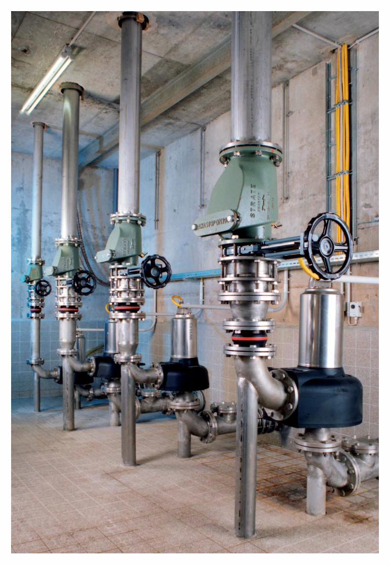

A D D I T I O N A L P L A N N I N G G U I D E
Wilo Sewage Engineering Planning Guide 2005 63
Discharge pipeline ventilation
Long holding times of sewage in dischargepipelines frequently result in unwanted odourscaused by hydrogen sulphide. Adding air preventsfouling of the sewage and keeps it "fresh." Litera-ture shows that in every two-hour period, asupply of air equal to 10% of the content of thepipeline is required to keep the sewage "fresh."The air supply to the discharge pipeline is pro-vided by a suitable compressor without a boiler.
Discharge pipe flushing or purging the discharge pipeline
If the flow velocity in a discharge pipeline doesnot reach the required minimum, or if a dischargepipeline is laid with high and low points (in thiscase, ventilation is only to the next high point),pressure flushing helps. The delivery rate of thecompressed air system should be selected suchthat the flow velocity of the water column or theindividual water plugs in the discharge pipeline isat least 1 m/s. In general, the calculations of therequired air pressure and the air quantity whenflushing or purging a discharge pipeline are to beequated with the calculation for the pump sys-tem. The velocity of the water column increasesas the discharge pipeline becomes increasinglyempty, corresponding to the compressed airsystem's properties. The system calculation isthus based on the theoretically least favourablecase, the beginning of the flushing or purgingprocess.
Grease separators
Grease separators are used to hold back organicoils and greases. Sewage with faecal mattercannot be introduced, nor can rainwater andsewage with mineral oils or greases. A greaseseparator consists of a sludge trap, the greaseseparator itself and a sampling point. Suspendedmatter is separated in the sludge trap. The sepa-ration of oils and greases in the grease separatortakes place using gravity alone. Emulsions anddispersions of oil and grease can be held backonly minimally or not at all.
Sewage or rainwater containing faecal mattermay not be introduced. Operation is limited towastewater.
If the separator is located below the backflowlevel, a lifting plant must be installed. The designof the grease separator will be determined by thewastewater inflow, the connected grease inlets ofthe installations (hotel, canteen kitchen, etc.) andthe density/concentration of the fluid.
Oil/petrol separator
Oil/petrol separators are used for environmentalprotection of natural bodies of water and sewersystems. Their functional principle is based onthe differences in specific density of water-insoluble materials. The materials on the surfaceof the water are separated from the water bycorresponding inlet systems and drained sepa-rately.
Peripherals
EN 1825-1DIN 4040
EN 12056

A D D I T I O N A L P L A N N I N G G U I D E
64 Subject to modifications 03/2005 WILO AG
Selecting switching devices
A wide variety of factors must be consideredwhen selecting switching devices. Thus, theselection of functions is not the only importantfactor; even more important is how well theelectrical part of the pump is tuned to theswitching device. The most important funda-mental is the tuning between the rated motorpower (setting + 10% over type plate informa-tion) at the corresponding nominal voltage and
the specified current of the switching device, asthe safety functions (tripping functions) such asmotor protection are based on these values.Furthermore, the switching device must be tunedto the installation. Thus, the installation locationhas to be considered here. This means makingsure that the switching device has the correctprotection class (IP) to prevent ingress of mois-ture. It is likewise of fundamental importance toobserve the explosion protection directives. Theswitching devices Wilo offers are designed for
Selecting switching devices for submersible pumps
ER1_A SK530incl. float switch
No. of pumps that can be connected 1 2 /1 possible
Electrical connection3~400 V � �
3~230 V � –1~230 V � �
Neutral conductor Not required Not requiredDirect start � �
Max. power for direct start P2 � 4 kW P2 � 3 kWCurrent for direct start 0.5-10 A 1-10 AStar-delta – –Max. power for star-delta – –Max. current for star-delta – –50 Hz frequency � �
Frequency 60 Hz � –Protection class IP 41 IP 41
Level systemsPneumatic pressure sensor (diving bell) – –Electronic pressure sensor (4-20 mA) (level sensor) – –Float switch(es) Yes (max. 2) Yes (max. 3)
Motor monitorEvaluation–thermal winding contact (WSK) � �
Evaluation–PTC � –Evaluation–leakage (Di) – –Electronic motor protection � �
Motor protection switch – –
Fault signals/run signalsCollective run signal � �
Collective fault signal � �
Individual run signal – �
Individual fault signal – �
Separate signal contact for high water – –Integrated alarm (buzzer) – –Battery-powered alarm (integrated battery) – –
Operation/displayLCD display – –Parameter adjustment Potentiometer PotentiometerMicroprocessor-controlled – –Version with plug and cable – –Main switch (3-pole) � –
SoftwarePump starts – –Elapsed time indicator – –Automatic pump duty cycling – �
GeneralAmbient temperature 0 to +40°C 0 to +40°CAdjustable delay time 0-120 sec. –Test run � –Logic reversal of inputs � –
Primary applicationTC 40, TS 40, TS 50, TC 40, TS 40, TS 50,TS 65, TP 50, TP 65, TS 65, TP 50, TP 65,TM/TMW 32, MTS 40, TM/TMW 32, MTS 40, STS 80, STC 80, CP STS 80, STC 80, CP
� Standard � Optional – Function not available

A D D I T I O N A L P L A N N I N G G U I D E
Wilo Sewage Engineering Planning Guide 2005 65
installation in "non-potentially explosive envi-ronments." This means that these devices maynot be installed in explosion-protected rooms.However, the switching device can be used inpotentially explosive areas by using Ex isolatingrelays and Zener barriers (also refer to "Ex iso-lating relay" on page 25 and "Zener barrier" onpage 29). These additional switch boxes areplaced between the switching device andpump/level control outside of the potentiallyexplosive area. The selection of the functions of
the switching device should be viewed in thecontext of the installation (information that canbe evaluated, signal functions, alarm etc.) andthe pump. The motor protection function (motormonitor) can be tripped in pumps in differentways, and thus is dependent on the capabilitiesof the switching device.
DrainControl 1 DrainControl 2 DrainControl PL1 DrainControl PL2 SK 545
1 2 1 2 / 1 possible 1 or 2
� � � � �
� � – – –� � � � –With/without With/without Required Required Not required� � � � –P2 � 4 kW P2 � 4 kW P2 � 4 kW P2 � 4 kW –0.5-10 A 0.5-10 A 0.3-12 A 0.3-12 A –� � – � –P2 � 5.5 kW P2 � 5.5 kW – � –55.1-71A 55.1-71 A – � –� � � � �
– – � � –IP 54 IP 54 IP 65 IP 65 IP 20
– – � � –� � � � –Yes (max. 5) Yes (max. 5) Yes (max. 3) Yes (max. 4) –
� � Yes (2x thermal winding contacts) Yes (2x thermal winding contacts) �
� � – – –� � – – �
� � � � –– – � � –
– – – – –� � � � –� � – – �
– – – � –– – � � –– – � � –– – – – –
� � � � –Menu-controlled/keys Menu-controlled/keys Menu-controlled/rotary knob Menu-controlled/rotary knob –� � � � –– – – – –� �
– – � � –� � � � –– � – � –
0 to +40°C 0 to +40°C -20 to +60°C -20 to +60°C 0 to +40°C0-60 sec. for base duty pump 0-60 sec. for base duty pump 0-180 sec. 0-180 sec. for base duty pump –– – � � –– – – – –
TC 40, TS 40, TS 50, TC 40, TS 40, TS 50, TC 40, TS 40, TS 50, TC 40, TS 40, TS 50, TP 80-150, MTS 40, TS 65, TP 50, TP 65, TS 65, TP 50, TP 65, TS 65, TP 50, TP 65, TS 65, TP 50, TP 65 CPTP 80-150, STS 80-100, TP 80-150, STS 80-100, MTS 40, STS 80, STC 80, MTS 40, STS 80, STC 80,STC 80-100, MTS 40, CP STC 80-100, MTS 40, CP CP CP

A D D I T I O N A L P L A N N I N G G U I D E
66 Subject to modifications 03/2005 WILO AG
Sump design/planning
• Sump size and pump selection are not the onlycritical factors when sizing a pump station.Rather, pipelines, fittings and installed parts ofthe sump such as pipework are of decisiveimportance.
• Always provide shut-off valves for service andrepair work. In some cases, these are alreadyprescribed by standards.
• End discharge pipelines must be sized in accor-dance with the parameters (such as flow veloc-ity) specified by the standards.
• Always place backflow valves at the top of thesump in the discharge pipeline, as this canprevent deposits.
• Sump bottoms should be designed at an angleof up to 40° to facilitate the inflow of solids tothe hydraulics of the pump.
• Provide baffles at the inlet of the sump toprevent damage to the pump from inflowingwater and to stabilise the fluid (prevents airfrom entering the pump).
• During the construction phase, provide a foun-dation earth electrode or earth strip for poten-tial equalisation.
• The non-return valve and the gate in the fittingshaft should be installed towards the very top ofthe pipe, so that they are easily accessible formaintenance, cleaning and inspection.
• To minimise water hammer, provide a waterhammer dampening system a short distanceabove the check valve (preferably with floatingball). Similar results can also be obtained using acheck valve with floating ball.
• If the transfer point (sewer) is below the sumplevel, vents must be provided, as otherwise thegenerated suction would completely drain theentire sump, including the pump. This results inventilation problems.
Sump design
A D D I T I O N A L P L A N N I N G G U I D E
Wilo Sewage Engineering Planning Guide 2005 67
Fault diagnostics (also refer to "Maintenance checklist" on page 70)
When does cavitation occur, and how can cavitation problems be solved?• Combination of vent line that is too small or
clogged with high fluid temperature. > Install/redimension or clean the vent line.
• Long suction line for pumps in dry sumpinstallation. > Select a suitable new pump.
• There is air and/or gas in the fluid. > Ensurethat the water coverage of the pump is cor-rect and/or install a baffle at the inlet so thatthe water jet does not impact close to thepump; change the position of the signaltransmitter.
• NPSHsystem > NPSHpump or NPSHpresent >NPSHrequired has not been followed whenselecting the pump. > Reduce the impellersize; reduce the delivery rate; reduce the fluidtemperature; reconfigure a suitable pump.
• Pump inlet is clogged. > Clean the inletpipeline or sump; clean the pump hydraulics.
• Fluid temperature is too high by a significantamount (> 75°C). > Select a suitable newpump.
• There is air in the pump/discharge pipelineand the pump cannot be ventilated. > Install avent line or clean the existing one.
• Pump has no counterpressure and runs out ofits curve towards the right. > Select a suitablepump; increase the resistances in the enddischarge pipeline by installing artificialresistance such as additional bends, pipelinewith higher pipe friction loss values etc.
Why does the pump not supply the desiredpump capacity (H, Q)?• Direction of rotation of the pump wrong
(possible with three-phase current only). > Reverse two phases (wires at the bus bar ofthe pump) to correct the direction of rotation.
• Impeller is damaged due to abrasion or corro-sion. > Replace damaged parts (such as cor-roded impeller).
• Pump inlet or impeller is clogged. > Clean hydraulics.
• Non-return valve is clogged or blocked. > Clean fitting.
• Gate valve in the discharge pipeline is notopen all the way. > Open gate valve all theway.
• There is air and/or gas in the fluid. > Ensurethat the water coverage of the pump is cor-rect and/or install a baffle at the inlet so thatthe water jet does not impact close to thepump.
• Motor bearings of the pump are defective. > Replace motor bearings–contact Wiloafter-sales service.
• Pump vent line is clogged (in case of deliveryhead problems). > Check and clean if neces-sary.
Why does the switching device trip the overcurrent/overload signal?• Mains voltage has dropped. > Check voltage
fluctuations.• Viscosity of the fluid is too high, resulting in a
higher load on the motor. > Reduce impellersize or configure a new pump.
• Pump does not run on the specified curve. > If necessary, restrict pump output usingshut-off valve to increase counterpressure.
• Temperature rise of the motor too high > Check number of starts and stops and, ifnecessary, limit them using the switchingdevice via a delay time.
• Direction of rotation of the pump wrong(possible with three-phase current only). > Reverse two phases (wires at the bus bar ofthe pump) to correct the direction of rotation.
• One phase of the power supply of the pumphas failed. > Check power supply connectionsand replace fuse if defective.
• Winding of the pump is defective. > Contact Wilo after-sales service.
• Motor bearings of the pump are defective. > Replace motor bearings–contact Wiloafter-sales service.
Fault diagnostics

A D D I T I O N A L P L A N N I N G G U I D E
68 Subject to modifications 03/2005 WILO AG
Why do the pump housing and dischargepipeline become clogged with deposits?• As a result of a lower flow rate, deposits settle
due to the decreased flow velocity > Checkthe duty point of the pump and pipelinesizing with regard to flow velocity.
• Too frequent operation with quantities thatare too small. > Redefine switching levels ofthe system (larger volume per pumpingprocess), increase delay time using theswitching device if necessary.
What causes water hammer and how can it beprevented/reduced?• When the pump starts, a large volume is
pushed through a small pipe diameter. > Check the duty point of the pump and pipe-line sizing with regard to the flow velocity.
• Air cushion(s) in the discharge pipeline. > Install vent valves directly above the non-return valve or in high points of the pipeline.
• Pump pumps the entire volume into thedischarge pipeline too quickly. > Switch fromtwo-pole pump to four-pole pump or use softstarter/frequency converter with start-upramp for slower pump start.
• Pump starts very frequently, causing irregularpressure waves to build up in the dischargepipeline. > Adjust delay time using theswitching device.
• Quick-closing fitting at the end of the dis-charge pipeline. > Replace fitting and useslow-closing fitting.
What causes noises of the non-return valveand how can they be reduced/prevented?• The valve does not close quickly enough and,
after the pump cuts out, is slammed onto thevalve seat by the water column that covers it.> Replace the valve with a quick-closingvalve, use a non-return valve with rubberseat, adjust the delay time using the switch-ing device.
Why is the pump/system too loud? How cannoise problems be solved?• Direction of rotation of the pump wrong
(possible with three-phase current only). > Reverse two phases (wires at the bus bar ofthe pump) to correct the direction of rotation.
• Impeller is damaged due to abrasion or corro-sion. > Replace damaged parts (such as cor-roded impeller).
• Pump inlet or impeller is clogged. > Cleanhydraulics.
• Motor bearings of the pump are defective. > Replace motor bearings–contact Wiloafter-sales service.
• Pump vent line is clogged. > Check and cleanif necessary.
• Fluid level in tank is too low. > Check levelswitch and readjust if necessary.
• Pipelines are causing vibration noises. > Check elastic connections and ensure thatpipelines are securely anchored in place,check wall ducts.
• Pump in sump can also be heard inside thebuilding. > Proper soundproofing is not inplace between sump and building; disconnectdirect, rigid connection between building andsump.
• System can be heard throughout the building.> System is not insulated from the floor/wall;use insulating strips to insulate it.
You can reach Wilo after-sales service at:
Phone (+49) 1805 W•I•L•O•K•D*9•4•5•6•5•3
or(+49) 231 41027900
*12 cents per minute
Representatives are available anytime between7 a.m. and 5 p.m.!
At the weekend and after hours, you can reach ususing our interactive voice response system withcall-back guarantee!

A N N E X
Wilo Sewage Engineering Planning Guide 2005 69
Checklists for installation, operation and maintenance
This list makes no claim to completeness, but is intended solely as an aid to orientation.
We disclaim any liability based on this information.
Checklist – Design
1. Determining the preconditionsDetermining the discharge criteria � Separate system � Combined system
Rainwater disposal Location of the building
(if in combined system) Consider effect of wind for rainwater � Yes � No
Rainfall to roof area °
Gutter length 1 m
Gutter length 2 m
Roof depth (vertical) m
Roof depth (horizontal) m
Type of building � Single-family home � Multi-family home
� Office building � Industrial building
� Public building
Installation criterion � Inside the building � Outside the building
Backflow level Backflow level or sump cover is located m
above the pump(s)
Installation Desired number of pumps pcs.of which pcs. are standby pump(s)
2. Defining the boundary conditionsCurrent/voltage supply � 1~220 V � 3~400 V � 50 Hz
� 1~230 V � 3~340 V � 60 Hz
Types of wastewater and sewage � Domestic sewage � Rainwater
� Industrial wastewater � Sea water
� Brackish water
Fluid contains faecal matter � Yes � No
Contains solids � Yes � No
Max. size of the solids: ø mm
Long-fibre particles in the fluid � Yes � No
pH value:
Fluid temperature: °C °F
Zone 1 explosion protection required � Yes � No
Additional information about the fluid:
Roof depth (hor. projection)
Roof depth (vert. projection)
Gutter length 2
Gutter length 1
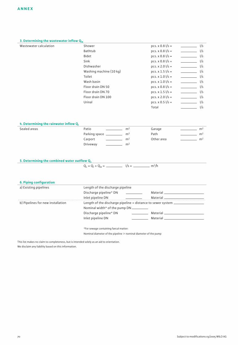
A N N E X
70 Subject to modifications 03/2005 WILO AG
3. Determining the wastewater inflow Qw
Wastewater calculation Shower pcs. x 0.8 l/s = l/s
Bathtub pcs. x 0.8 l/s = l/s
Bidet pcs. x 0.8 l/s = l/s
Sink pcs. x 0.8 l/s = l/s
Dishwasher pcs. x 2.0 l/s = l/s
Washing machine (10 kg) pcs. x 1.5 l/s = l/s
Toilet pcs. x 1.0 l/s = l/s
Wash basin pcs. x 1.0 l/s = l/s
Floor drain DN 50 pcs. x 0.8 l/s = l/s
Floor drain DN 70 pcs. x 1.5 l/s = l/s
Floor drain DN 100 pcs. x 2.0 l/s = l/s
Urinal pcs. x 0.5 l/s = l/s
Total l/s
4. Determining the rainwater inflow Qr
Sealed areas Patio m2 Garage m2
Parking space m2 Path m2
Carport m2 Other area m2
Driveway m2
5. Determining the combined water outflow Qc
Qc = Qr + Qw = l/s = m3/h
6. Piping configurationa) Existing pipelines Length of the discharge pipeline
Discharge pipeline* DN Material
Inlet pipeline DN Material
b) Pipelines for new installation Length of the discharge pipeline = distance to sewer system
Nominal width* of the pump DN
Discharge pipeline* DN Material
Inlet pipeline DN Material
*For sewage containing faecal matter:
Nominal diameter of the pipeline � nominal diameter of the pump
This list makes no claim to completeness, but is intended solely as an aid to orientation.
We disclaim any liability based on this information.
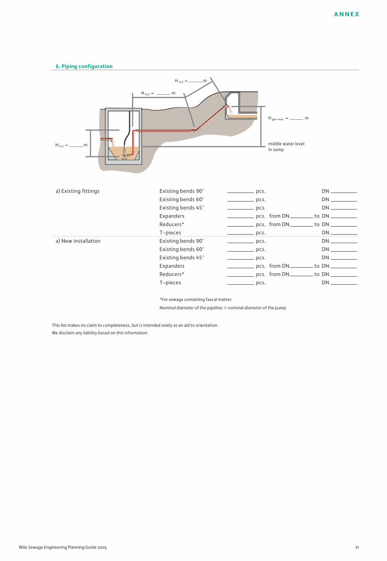
A N N E X
Wilo Sewage Engineering Planning Guide 2005 71
6. Piping configuration
a) Existing fittings Existing bends 90° pcs. DN
Existing bends 60° pcs. DN
Existing bends 45° pcs. DN
Expanders pcs. from DN to DN
Reducers* pcs. from DN to DN
T-pieces pcs. DN
a) New installation Existing bends 90° pcs. DN
Existing bends 60° pcs. DN
Existing bends 45° pcs. DN
Expanders pcs. from DN to DN
Reducers* pcs. from DN to DN
T-pieces pcs. DN
*For sewage containing faecal matter:
Nominal diameter of the pipeline � nominal diameter of the pump
This list makes no claim to completeness, but is intended solely as an aid to orientation.
We disclaim any liability based on this information.
H geo-max = m
H VL1 = m
H VL2 = m
H VL3 = m
middle water levelin sump

A N N E X
72 Subject to modifications 03/2005 WILO AG
Checklist for selecting switching devices Yes / No
Ambient temperature ºC
Delay time sec.
Test run � / �
Evaluation information
Pump starts � / �
Elapsed time indicator � / �
Automatic pump duty cycling � / �
Number of pumps that can be connected pcs.
Control functions
Pneumatic pressure sensor (diving bell) � / �
Electronic pressure sensor (level sensor = pressure sensor) � / �
Float switch � / �
Electrical connection
1~230 V � / �
3~230 V � / �
3~400 V � / �
Neutral conductor � / �
Direct start � / �
Star/delta start � / �
Max. current strength (see pump type plate) A
Frequency Hz
Protection class IP
Motor monitor
Evaluation via thermal winding contacts � / �
Evaluation via PTC � / �
Leak monitoring � / �
Electronic motor protection � / �
Motor protection switch
Fault/run signals
Collective run signal � / �
Collective fault signal � / �
Individual run signal � / �
Individual fault signal � / �
Separate high water signal contact � / �
Integrated alarm (buzzer) � / �
Battery-powered alarm � / �
Display/operation
LCD display � / �
LEDs � / �
Red button � / �
Type of function
Microprocessor-controlled � / �
Electronic � / �
Electro-mechanical � / �
Version
Main switch � / �
Switching device with plug and cable � / �
This list makes no claim to completeness, but is intended solely as an aid to orientation.
We disclaim any liability based on this information..
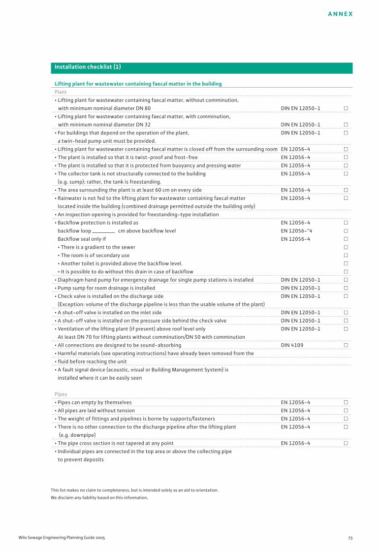
A N N E X
Wilo Sewage Engineering Planning Guide 2005 73
This list makes no claim to completeness, but is intended solely as an aid to orientation.
We disclaim any liability based on this information.
Installation checklist (1)
Lifting plant for wastewater containing faecal matter in the buildingPlant
• Lifting plant for wastewater containing faecal matter, without comminution,
with minimum nominal diameter DN 80 DIN EN 12050-1 �
• Lifting plant for wastewater containing faecal matter, with comminution,
with minimum nominal diameter DN 32 DIN EN 12050-1 �
• For buildings that depend on the operation of the plant, DIN EN 12050-1 �
a twin-head pump unit must be provided.
• Lifting plant for wastewater containing faecal matter is closed off from the surrounding room EN 12056-4 �
• The plant is installed so that it is twist-proof and frost-free EN 12056-4 �
• The plant is installed so that it is protected from buoyancy and pressing water EN 12056-4 �
• The collector tank is not structurally connected to the building EN 12056-4 �
(e.g. sump); rather, the tank is freestanding.
• The area surrounding the plant is at least 60 cm on every side EN 12056-4 �
• Rainwater is not fed to the lifting plant for wastewater containing faecal matter EN 12056-4 �
located inside the building (combined drainage permitted outside the building only)
• An inspection opening is provided for freestanding-type installation
• Backflow protection is installed as EN 12056-4 �
backflow loop cm above backflow level EN 12056-"4 �
Backflow seal only if EN 12056-4 �
• There is a gradient to the sewer �
• The room is of secondary use �
• Another toilet is provided above the backflow level. �
• It is possible to do without this drain in case of backflow �
• Diaphragm hand pump for emergency drainage for single pump stations is installed DIN EN 12050-1 �
• Pump sump for room drainage is installed DIN EN 12050-1 �
• Check valve is installed on the discharge side DIN EN 12050-1 �
(Exception: volume of the discharge pipeline is less than the usable volume of the plant)
• A shut-off valve is installed on the inlet side DIN EN 12050-1 �
• A shut-off valve is installed on the pressure side behind the check valve DIN EN 12050-1 �
• Ventilation of the lifting plant (if present) above roof level only DIN EN 12050-1 �
At least DN 70 for lifting plants without comminution/DN 50 with comminution
• All connections are designed to be sound-absorbing DIN 4109 �
• Harmful materials (see operating instructions) have already been removed from the
• fluid before reaching the unit
• A fault signal device (acoustic, visual or Building Management System) is
installed where it can be easily seen
Pipes
• Pipes can empty by themselves EN 12056-4 �
• All pipes are laid without tension EN 12056-4 �
• The weight of fittings and pipelines is borne by supports/fasteners EN 12056-4 �
• There is no other connection to the discharge pipeline after the lifting plant EN 12056-4 �
(e.g. downpipe)
• The pipe cross section is not tapered at any point EN 12056-4 �
• Individual pipes are connected in the top area or above the collecting pipe
to prevent deposits

A N N E X
74 Subject to modifications 03/2005 WILO AG
This list makes no claim to completeness, but is intended solely as an aid to orientation.
We disclaim any liability based on this information.
Installation checklist (2)
Operational reliability• The selected duty point lies in the middle one-third �
of the hydraulic curve provided by the manufacturer in order to achieve optimum capacity utilisation
and service life
• The free passage of the pump is sized according to the �
requirements
• NPSHsystem > NPSHpump or NPSHpresent > NPSHrequired �
• Sufficient access for service and maintenance is guaranteed �
• The units are adequately protected from external influences �
• The power supply has been checked with regard to voltage fluctuations �
• Corresponding settings have been made on the switching device �
• The position of the switching device is flood-proof �
• There are no reducers in the discharge line EN 12056-2 �
Limited-use plant• The plant is installed below the backflow level (for renovation, also permitted EN 12056-1 �
above the plant)
• The plant is installed immediately behind the toilet EN 12056-1 �
• All connected drainage sources are in the EN 12056-1 �
same room
• The plant is on the same level as the toilet EN 12056-1 �
• No bathtubs, washing machines or dishwashers are EN 12056-1 �
connected
• No separate ventilation is connected DIN EN 12050-3 �
• Ventilation takes place free of odour via the built-in ventilation of the plant DIN EN 12050-3 �
• The minimum inner diameter of the discharge pipeline and the following fittings DIN EN 12050-3 �
is at least 20 mm for units with comminution
(for those without comminution, 25 mm)
• There is a toilet above the backflow level with free gravity flow to the sewer DIN EN 12050-3 �
• The end user has been informed of the danger of clogs caused by sanitary napkins, condoms etc. DIN EN 12050-3 �
Pumping stations (outside the building)• Pipes have been laid on a steady uphill/downhill incline without high and low points �
• Vent valves are installed in high points �
• The minimum flow velocity is assured at all times �
• For pressure drainage, the contents of the pipeline are flushed at least � 8 hers. (EN 1671); �
Recommendation: flush � 4 hers.!
• All fittings have the same free passage as the pipeline �
• The pump sump has a funnel shape with ° incline for better �
inflow of the fluid to the pump
• The surfaces of the pump sump are smooth �
• All construction debris has been removed and the pump sump is clean �
• The sump can hold the pipeline volume �
• The exit losses have been taken into consideration in the design �
• The compaction of the sump is in accordance with ATV-A 139 and/or DIN EN 1610 DIN EN 1610 �
• A pressure test has been conducted in accordance with the applicable directives for
a pressure drainage station (high points must first be bled) DIN 4279 T1–T9 �
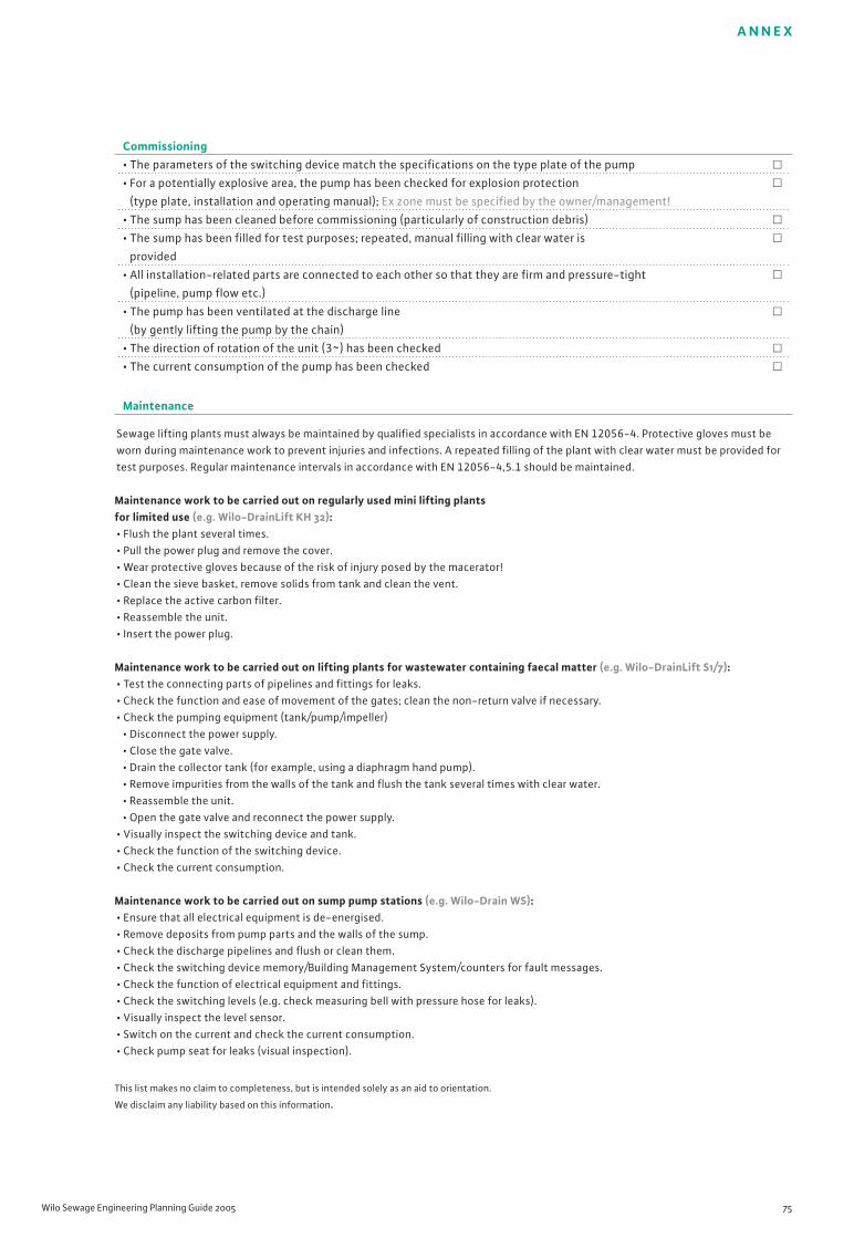
A N N E X
Wilo Sewage Engineering Planning Guide 2005 75
This list makes no claim to completeness, but is intended solely as an aid to orientation.
We disclaim any liability based on this information.
Commissioning• The parameters of the switching device match the specifications on the type plate of the pump �
• For a potentially explosive area, the pump has been checked for explosion protection �
(type plate, installation and operating manual); Ex zone must be specified by the owner/management!
• The sump has been cleaned before commissioning (particularly of construction debris) �
• The sump has been filled for test purposes; repeated, manual filling with clear water is �
provided
• All installation-related parts are connected to each other so that they are firm and pressure-tight �
(pipeline, pump flow etc.)
• The pump has been ventilated at the discharge line �
(by gently lifting the pump by the chain)
• The direction of rotation of the unit (3~) has been checked �
• The current consumption of the pump has been checked �
Maintenance
Sewage lifting plants must always be maintained by qualified specialists in accordance with EN 12056-4. Protective gloves must beworn during maintenance work to prevent injuries and infections. A repeated filling of the plant with clear water must be provided fortest purposes. Regular maintenance intervals in accordance with EN 12056-4,5.1 should be maintained.
Maintenance work to be carried out on regularly used mini lifting plants for limited use (e.g. Wilo-DrainLift KH 32):• Flush the plant several times.• Pull the power plug and remove the cover.• Wear protective gloves because of the risk of injury posed by the macerator!• Clean the sieve basket, remove solids from tank and clean the vent.• Replace the active carbon filter.• Reassemble the unit.• Insert the power plug.
Maintenance work to be carried out on lifting plants for wastewater containing faecal matter (e.g. Wilo-DrainLift S1/7):• Test the connecting parts of pipelines and fittings for leaks.• Check the function and ease of movement of the gates; clean the non-return valve if necessary.• Check the pumping equipment (tank/pump/impeller)
• Disconnect the power supply.• Close the gate valve.• Drain the collector tank (for example, using a diaphragm hand pump).• Remove impurities from the walls of the tank and flush the tank several times with clear water.• Reassemble the unit.• Open the gate valve and reconnect the power supply.
• Visually inspect the switching device and tank.• Check the function of the switching device.• Check the current consumption.
Maintenance work to be carried out on sump pump stations (e.g. Wilo-Drain WS):• Ensure that all electrical equipment is de-energised.• Remove deposits from pump parts and the walls of the sump.• Check the discharge pipelines and flush or clean them.• Check the switching device memory/Building Management System/counters for fault messages.• Check the function of electrical equipment and fittings.• Check the switching levels (e.g. check measuring bell with pressure hose for leaks).• Visually inspect the level sensor.• Switch on the current and check the current consumption.• Check pump seat for leaks (visual inspection).
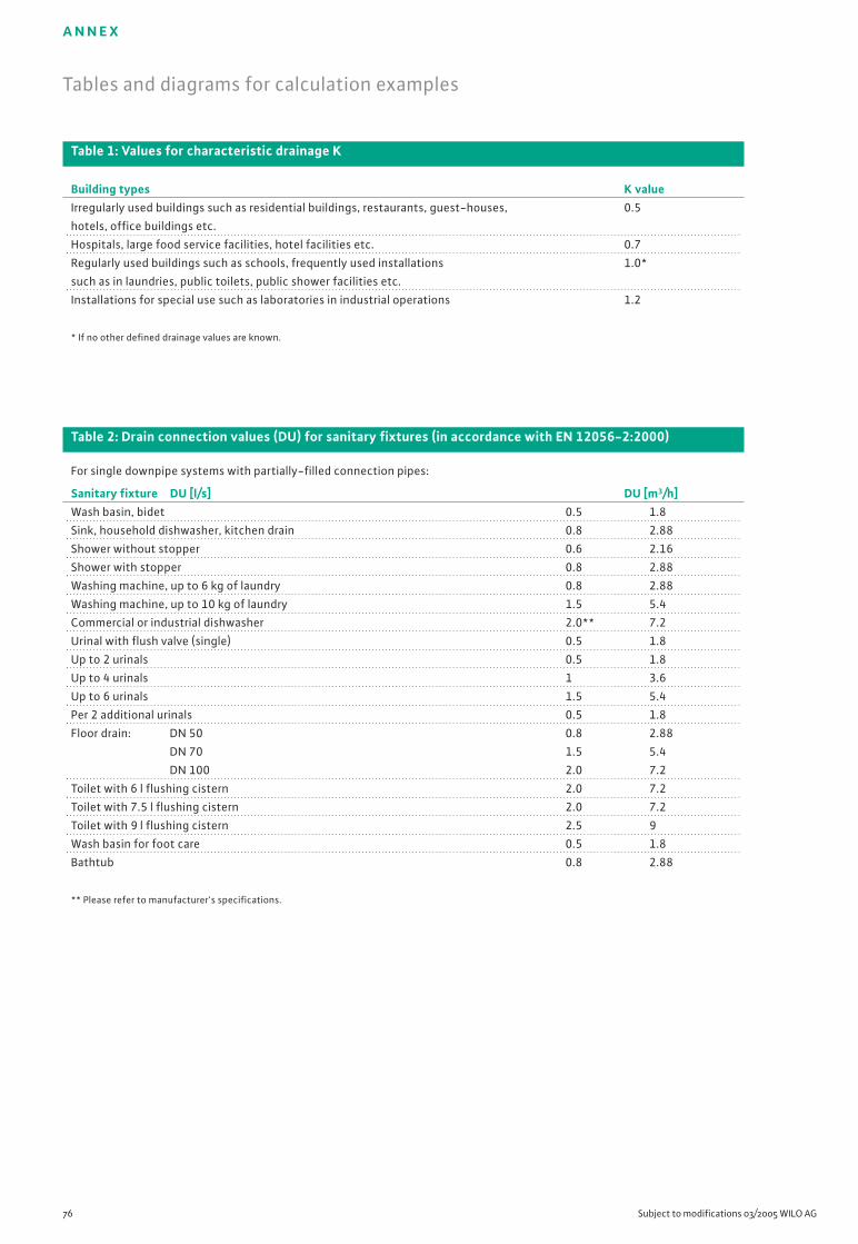
A N N E X
76 Subject to modifications 03/2005 WILO AG
Table 1: Values for characteristic drainage K
Building types K value Irregularly used buildings such as residential buildings, restaurants, guest-houses, 0.5
hotels, office buildings etc.
Hospitals, large food service facilities, hotel facilities etc. 0.7
Regularly used buildings such as schools, frequently used installations 1.0*
such as in laundries, public toilets, public shower facilities etc.
Installations for special use such as laboratories in industrial operations 1.2
* If no other defined drainage values are known.
Table 2: Drain connection values (DU) for sanitary fixtures (in accordance with EN 12056-2:2000)
For single downpipe systems with partially-filled connection pipes:
Sanitary fixture DU [l/s] DU [m3/h]Wash basin, bidet 0.5 1.8
Sink, household dishwasher, kitchen drain 0.8 2.88
Shower without stopper 0.6 2.16
Shower with stopper 0.8 2.88
Washing machine, up to 6 kg of laundry 0.8 2.88
Washing machine, up to 10 kg of laundry 1.5 5.4
Commercial or industrial dishwasher 2.0** 7.2
Urinal with flush valve (single) 0.5 1.8
Up to 2 urinals 0.5 1.8
Up to 4 urinals 1 3.6
Up to 6 urinals 1.5 5.4
Per 2 additional urinals 0.5 1.8
Floor drain: DN 50 0.8 2.88
DN 70 1.5 5.4
DN 100 2.0 7.2
Toilet with 6 l flushing cistern 2.0 7.2
Toilet with 7.5 l flushing cistern 2.0 7.2
Toilet with 9 l flushing cistern 2.5 9
Wash basin for foot care 0.5 1.8
Bathtub 0.8 2.88
** Please refer to manufacturer's specifications.
Tables and diagrams for calculation examples
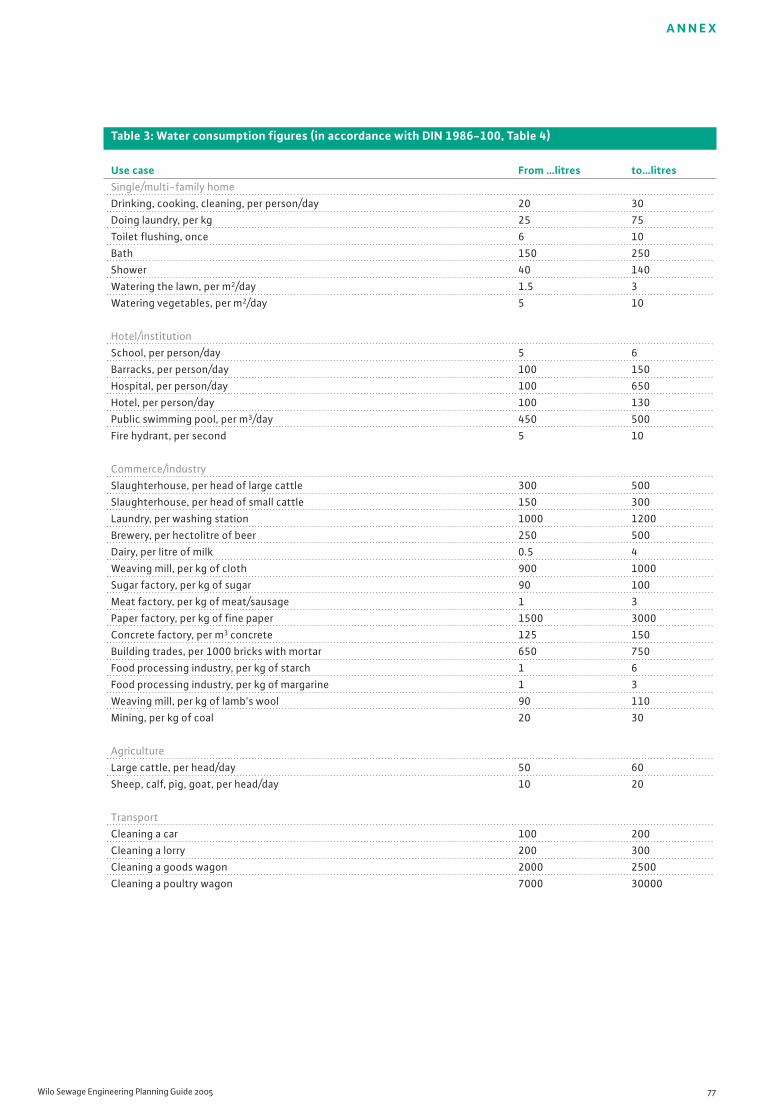
A N N E X
Wilo Sewage Engineering Planning Guide 2005 77
Table 3: Water consumption figures (in accordance with DIN 1986-100, Table 4)
Use case From …litres to…litresSingle/multi-family home
Drinking, cooking, cleaning, per person/day 20 30
Doing laundry, per kg 25 75
Toilet flushing, once 6 10
Bath 150 250
Shower 40 140
Watering the lawn, per m2/day 1.5 3
Watering vegetables, per m2/day 5 10
Hotel/institution
School, per person/day 5 6
Barracks, per person/day 100 150
Hospital, per person/day 100 650
Hotel, per person/day 100 130
Public swimming pool, per m3/day 450 500
Fire hydrant, per second 5 10
Commerce/industry
Slaughterhouse, per head of large cattle 300 500
Slaughterhouse, per head of small cattle 150 300
Laundry, per washing station 1000 1200
Brewery, per hectolitre of beer 250 500
Dairy, per litre of milk 0.5 4
Weaving mill, per kg of cloth 900 1000
Sugar factory, per kg of sugar 90 100
Meat factory, per kg of meat/sausage 1 3
Paper factory, per kg of fine paper 1500 3000
Concrete factory, per m3 concrete 125 150
Building trades, per 1000 bricks with mortar 650 750
Food processing industry, per kg of starch 1 6
Food processing industry, per kg of margarine 1 3
Weaving mill, per kg of lamb's wool 90 110
Mining, per kg of coal 20 30
Agriculture
Large cattle, per head/day 50 60
Sheep, calf, pig, goat, per head/day 10 20
Transport
Cleaning a car 100 200
Cleaning a lorry 200 300
Cleaning a goods wagon 2000 2500
Cleaning a poultry wagon 7000 30000

A N N E X
78 Subject to modifications 03/2005 WILO AG
Table 4: Rainfall intensities in Germany (excerpt from DIN 1986-100:2002-03 Table A1)
rX(Y) means a rainfall intensity that lasts for X minutes (duration) and statistically occurs every 1/Y years.
Example: r5(0.5) Five-minute rain that statistically occurs every 1/0.5 (=2) every 2 years.
Location r5.2 r15.2 r5.30 r15.30 r5.100
[l/(s x ha)] [l/(s x ha)] [l/(s x ha)] [l/(s x ha)] [l/(s x ha)]Aachen 240 121 431 214 516
Aschaffenburg 293 143 539 267 649
Augsburg 285 138 499 243 595
Aurich 240 121 416 214 494
Bad Salzuflen 282 133 455 233 532
Bad Tölz 416 205 655 355 762
Bayreuth 285 144 524 276 630
Berlin 341 169 605 321 723
Bielefeld 260 132 475 248 570
Bonn 266 132 505 248 611
Braunschweig 289 143 498 267 591
Bremen 238 118 403 202 477
Chemnitz 340 162 552 288 646
Cottbus 260 129 477 232 574
Dessau 292 137 530 250 635
Dortmund 277 134 441 226 513
Dresden 297 145 540 268 648
Düsseldorf 227 135 518 245 626
Eisenach 269 135 478 249 570
Emden 246 124 444 230 532
Erfurt 243 121 404 214 476
Frankfurt/Main 314 145 577 268 695
Halle/Saale 285 137 503 250 601
Hamburg 258 129 423 232 497
Hannover 275 124 538 230 655
Heidelberg 338 158 579 287 686
Ingolstadt 283 138 456 243 534
Kassel 273 140 505 266 608
Kiel 230 112 404 192 481
Köln 281 138 535 266 648
Leipzig 324 147 545 276 690
Lingen 316 148 588 284 709
Magdeburg 277 129 517 232 624
Mainz 333 164 603 304 723
Munich 335 166 577 305 685
Münster 283 137 510 250 611
Neubrandenburg 330 148 607 284 731
Nuremberg 296 145 533 272 638
Rosenheim 402 191 733 350 880
Rostock 232 118 375 202 438
Saarbrücken 255 131 448 240 534
Stuttgart 349 169 663 325 802
Würzburg 293 140 511 266 608

A N N E X
Wilo Sewage Engineering Planning Guide 2005 79
Table 5: Runoff coefficients C for calculating the rainfall rate Qr
(DIN 1986-100:2002-03, Table 6)
No. Type of surfaces Runoff coefficient C1 Impermeable surfaces, such as
• Sloping roofs > 3° incline 1.0
• Concrete surfaces 1.0
• Ramps 1.0
• Hardened surfaces with joint packing 1.0
• Bituminous pavement 1.0
• Pavement with joint sealing 1.0
• Sloping roofs ≤3° incline 1.0
• Gravel roofs 0.8
• Green roofs*
• For intensive greening 0.5
• For extensive greening with system thickness of 10 cm or more 0.3
• For extensive greening with system thickness less than 10 cm 0.5
2 Semi-permeable and low-runoff surfaces, such as:
• Unpaved streets, courtyards, promenades 0.5
• Surfaces with slabs
• Paved surfaces with joints > 15% of total area 0.6
e.g. 10 cm x 10 cm and smaller
• Waterbound surfaces 0.5
• Playgrounds with partial revetment 0.3
• Sports fields with drainage
• Synthetic surfaces, artificial turf 0.6
• Tennis courts and similar sports surfaces 0.4
• Grass surfaces 0.3
3 Permeable surfaces with little or no runoff, such as:
• Parks and planting areas, gravel and 0.0
slag surfaces, pebbles, also with partially hardened surfaces such as:
• Garden paths with waterbound covering 0.0
• Driveways and single parking spaces with turfstone 0.0
* According to "Guidelines for the planning, execution and upkeep of green-roof sites – Guidelines for green-roof sites"
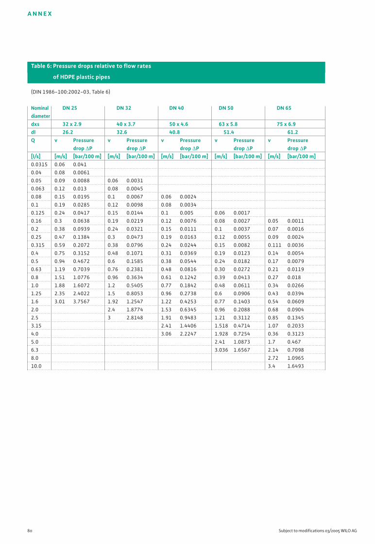
A N N E X
80 Subject to modifications 03/2005 WILO AG
Table 6: Pressure drops relative to flow rates
of HDPE plastic pipes
(DIN 1986-100:2002-03, Table 6)
Nominal DN 25 DN 32 DN 40 DN 50 DN 65diameterdxs 32 x 2.9 40 x 3.7 50 x 4.6 63 x 5.8 75 x 6.9dl 26.2 32.6 40.8 51.4 61.2Q v Pressure v Pressure v Pressure v Pressure v Pressure
drop ∆P drop ∆P drop ∆P drop ∆P drop ∆P[l/s] [m/s] [bar/100 m] [m/s] [bar/100 m] [m/s] [bar/100 m] [m/s] [bar/100 m] [m/s] [bar/100 m]0.0315 0.06 0.041
0.04 0.08 0.0061
0.05 0.09 0.0088 0.06 0.0031
0.063 0.12 0.013 0.08 0.0045
0.08 0.15 0.0195 0.1 0.0067 0.06 0.0024
0.1 0.19 0.0285 0.12 0.0098 0.08 0.0034
0.125 0.24 0.0417 0.15 0.0144 0.1 0.005 0.06 0.0017
0.16 0.3 0.0638 0.19 0.0219 0.12 0.0076 0.08 0.0027 0.05 0.0011
0.2 0.38 0.0939 0.24 0.0321 0.15 0.0111 0.1 0.0037 0.07 0.0016
0.25 0.47 0.1384 0.3 0.0473 0.19 0.0163 0.12 0.0055 0.09 0.0024
0.315 0.59 0.2072 0.38 0.0796 0.24 0.0244 0.15 0.0082 0.111 0.0036
0.4 0.75 0.3152 0.48 0.1071 0.31 0.0369 0.19 0.0123 0.14 0.0054
0.5 0.94 0.4672 0.6 0.1585 0.38 0.0544 0.24 0.0182 0.17 0.0079
0.63 1.19 0.7039 0.76 0.2381 0.48 0.0816 0.30 0.0272 0.21 0.0119
0.8 1.51 1.0776 0.96 0.3634 0.61 0.1242 0.39 0.0413 0.27 0.018
1.0 1.88 1.6072 1.2 0.5405 0.77 0.1842 0.48 0.0611 0.34 0.0266
1.25 2.35 2.4022 1.5 0.8053 0.96 0.2738 0.6 0.0906 0.43 0.0394
1.6 3.01 3.7567 1.92 1.2547 1.22 0.4253 0.77 0.1403 0.54 0.0609
2.0 2.4 1.8774 1.53 0.6345 0.96 0.2088 0.68 0.0904
2.5 3 2.8148 1.91 0.9483 1.21 0.3112 0.85 0.1345
3.15 2.41 1.4406 1.518 0.4714 1.07 0.2033
4.0 3.06 2.2247 1.928 0.7254 0.36 0.3123
5.0 2.41 1.0873 1.7 0.467
6.3 3.036 1.6567 2.14 0.7098
8.0 2.72 1.0965
10.0 3.4 1.6493

A N N E X
Wilo Sewage Engineering Planning Guide 2005 81
Table 6: Pressure drops relative to flow rates
of HDPE plastic pipes
(continued)
Nominal DN 80 DN 100 DN 100 DN 125 DN 150diameterdxs 90 x 8.2 110 x 10.0 125 x 11.4 140 x 12.8 160 x 14.6dl 73.6 90 102.2 114.4 130.8Q v Pressure v Pressure v Pressure v Pressure v Pressure
drop ∆P drop ∆P drop ∆P drop ∆P drop ∆P[l/s] [m/s] [bar/100 m] [m/s] [bar/100 m] [m/s] [bar/100 m] [m/s] [bar/100 m] [m/s] [bar/100 m]0.3 0.06 0.01
0.3 0.07 0.0015
0.4 0.09 0.0023 0.06 0.0009
0.5 0.12 0.0033 0.08 0.0013 0.06 0.0007
0.6 0.15 0.0049 0.1 0.0019 0.08 0.001 0.06 0.0006
0.8 0.19 0.0075 0.13 0.0029 0.1 0.0016 0.08 0.0009 0.06 0.0005
1.0 0.24 0.0111 0.16 0.0043 0.12 0.0023 0.1 0.0014 0.07 0.0007
1.3 0.29 0.0163 0.2 0.0063 0.15 0.0034 0.12 0.0002 0.09 0.0011
1.6 0.38 0.0252 0.25 0.0097 0.2 0.0054 0.16 0.0031 0.12 0.0016
2.0 0.47 0.0374 0.31 0.0143 0.24 0.0078 0.2 0.0046 0.015 0.0024
2.5 0.59 0.0555 0.39 0.0212 0.31 0.0116 0.24 0.0068 0.19 0.0036
3.2 0.74 0.0838 0.5 0.032 0.38 0.0174 0.31 0.0102 0.23 0.0054
4.0 0.94 0.1285 0.63 0.489 0.49 0.0266 0.39 0.0155 0.3 0.0082
5.0 1.18 0.1917 0.79 0.0729 0.61 0.0396 0.49 0.0231 0.37 0.0121
6.3 1.48 0.2908 0.99 0.1103 0.77 0.0598 0.61 0.0348 0.47 0.0183
8.0 1.88 0.448 1.26 0.1695 0.98 0.0919 0.78 0.0534 0.6 0.0281
10.0 2.35 0.6722 1.57 0.2537 1.22 0.1373 0.97 0.0797 0.74 0.0419
13.0 2.94 1.0104 1.97 0.3804 1.52 0.2056 1.22 0.1193 0.93 0.0625
16.0 2.52 0.5966 1.95 0.3219 1.56 0.1865 1.19 0.0976
20.0 3.14 0.8977 2.44 0.4836 1.95 0.2798 1.49 0.1463
25.0 3.05 0.7279 2.43 0.4205 1.86 0.2195
32.0 3.0650 0.6424 2.34 0.3347
40.0 2.98 0.5188
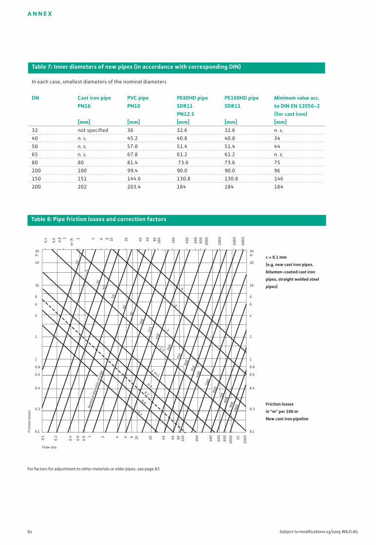
c = 0.1 mm
(e.g. new cast iron pipes,
bitumen-coated cast iron
pipes, straight welded steel
pipes)
Friction losses
in "m" per 100 m
New cast iron pipeline
A N N E X
82 Subject to modifications 03/2005 WILO AG
Table 7: Inner diameters of new pipes (in accordance with corresponding DIN)
In each case, smallest diameters of the nominal diameters
DN Cast iron pipe PVC pipe PE80HD pipe PE100HD pipe Minimum value acc.PN16 PN10 SDR11 SDR11 to DIN EN 12056-2
PN12.5 (for cast iron)[mm] [mm] [mm] [mm] [mm]
32 not specified 36 32.6 32.6 n. s.
40 n. s. 45.2 40.8 40.8 34
50 n. s. 57.0 51.4 51.4 44
65 n. s. 67.8 61.2 61.2 n. s.
80 80 81.4 73.6 73.6 75
100 100 99.4 90.0 90.0 96
150 151 144.6 130.8 130.8 146
200 202 203.4 184 184 184
30m
20
10
8
6
4
2
1
0.8
0.6
0.4
0.2
0.1
Flow rate
30m
20
10
8
6
4
2
1
0.8
0.6
0.4
0.2
0.1
0.1
Fric
tion
loss
es
10 20 40 60 800.2
0.6
0.8 1 2 4 6 8
100
200
400
600
800
100
0
200
0
0,4
0,6
0,8 1
m3/h 2 4 6 8 10 20 40 60 80 100
200
400
600
800
100
0
200
0
400
0
600
0
40
50
65
Nom
inal
dia
met
er o
f pip
e
20
25
32
80
100
125
150
200
250
300
350
400
500
600
700
800
900
1000
0.4
0.6
0.7
0.8
1.5
1 m/s
2
3
4
0.4 l/s
For factors for adjustment to other materials or older pipes, see page 83
Table 8: Pipe friction losses and correction factors
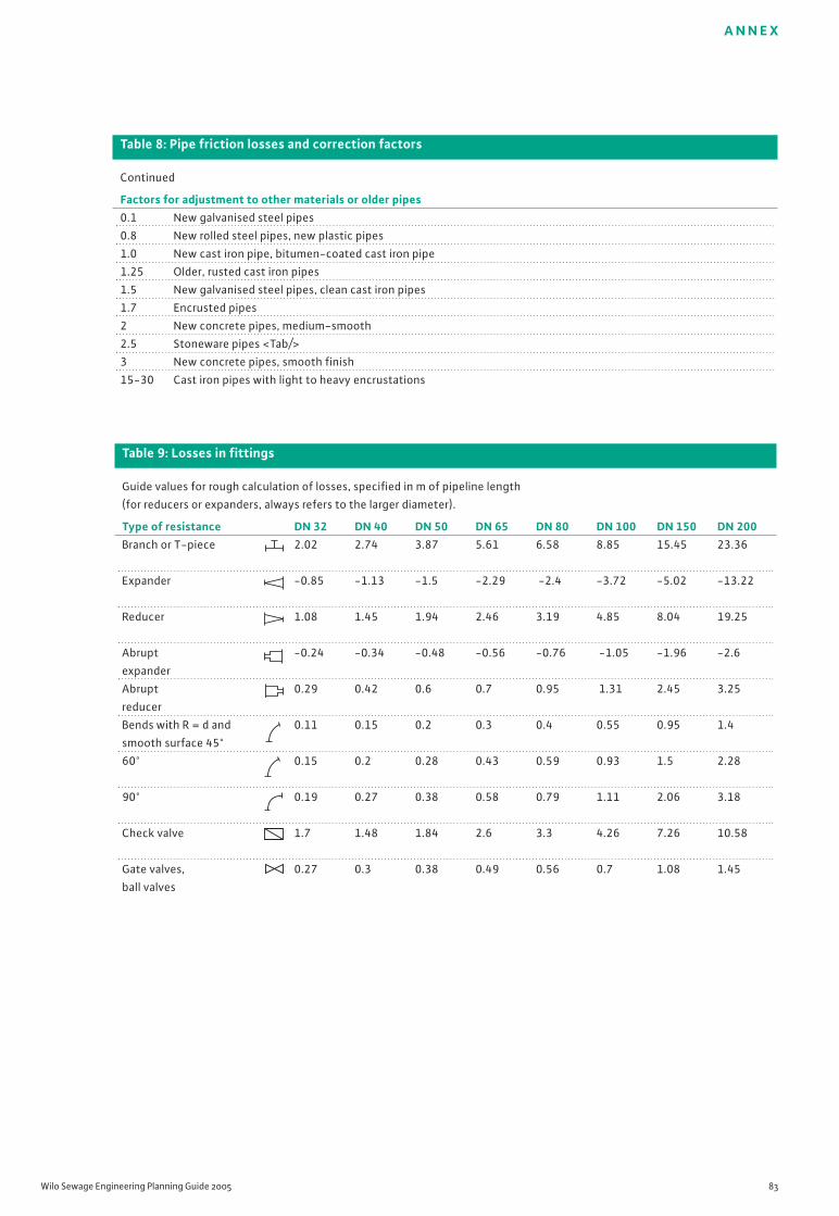
Table 8: Pipe friction losses and correction factors
Continued
Factors for adjustment to other materials or older pipes0.1 New galvanised steel pipes
0.8 New rolled steel pipes, new plastic pipes
1.0 New cast iron pipe, bitumen-coated cast iron pipe
1.25 Older, rusted cast iron pipes
1.5 New galvanised steel pipes, clean cast iron pipes
1.7 Encrusted pipes
2 New concrete pipes, medium-smooth
2.5 Stoneware pipes <Tab/>
3 New concrete pipes, smooth finish
15-30 Cast iron pipes with light to heavy encrustations
A N N E X
Wilo Sewage Engineering Planning Guide 2005 83
Table 9: Losses in fittings
Guide values for rough calculation of losses, specified in m of pipeline length
(for reducers or expanders, always refers to the larger diameter).
Type of resistance DN 32 DN 40 DN 50 DN 65 DN 80 DN 100 DN 150 DN 200Branch or T-piece 2.02 2.74 3.87 5.61 6.58 8.85 15.45 23.36
Expander -0.85 -1.13 -1.5 -2.29 -2.4 -3.72 -5.02 -13.22
Reducer 1.08 1.45 1.94 2.46 3.19 4.85 8.04 19.25
Abrupt -0.24 -0.34 -0.48 -0.56 -0.76 -1.05 -1.96 -2.6
expander
Abrupt 0.29 0.42 0.6 0.7 0.95 1.31 2.45 3.25
reducer
Bends with R = d and 0.11 0.15 0.2 0.3 0.4 0.55 0.95 1.4
smooth surface 45°
60° 0.15 0.2 0.28 0.43 0.59 0.93 1.5 2.28
90° 0.19 0.27 0.38 0.58 0.79 1.11 2.06 3.18
Check valve 1.7 1.48 1.84 2.6 3.3 4.26 7.26 10.58
Gate valves, 0.27 0.3 0.38 0.49 0.56 0.7 1.08 1.45
ball valves
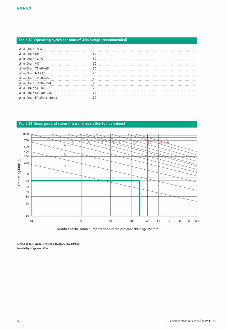
A N N E X
84 Subject to modifications 03/2005 WILO AG
Table 10: Operating cycles per hour of Wilo pumps (recommended)
Wilo-Drain TMW 30
Wilo-Drain CP 15
Wilo-Drain TC 40 30
Wilo-Drain VC 20
Wilo-Drain TS 40–65 20
Wilo-Drain MTS 40 20
Wilo-Drain TP 50–65 20
Wilo-Drain TP 80–150 20
Wilo-Drain STS 80–100 20
Wilo-Drain STC 80–100 15
Wilo-Drain FA 15.xx–20.xx 10
Table 11: Sump pump stations in parallel operation (guide values)
10 20 30 40 50 60 70 80 90 100
Number of the sump pump stations in the pressure drainage system
Ope
rati
ng t
ime
[s]
1000
700
500
400
300
200
100
70
50
40
30
20
10
2
3
45 6 7 8 9 10 12 14 16
According to T. Szabo, Debrecan, Hungary (KA 8/1988)
Probability of approx. 95%
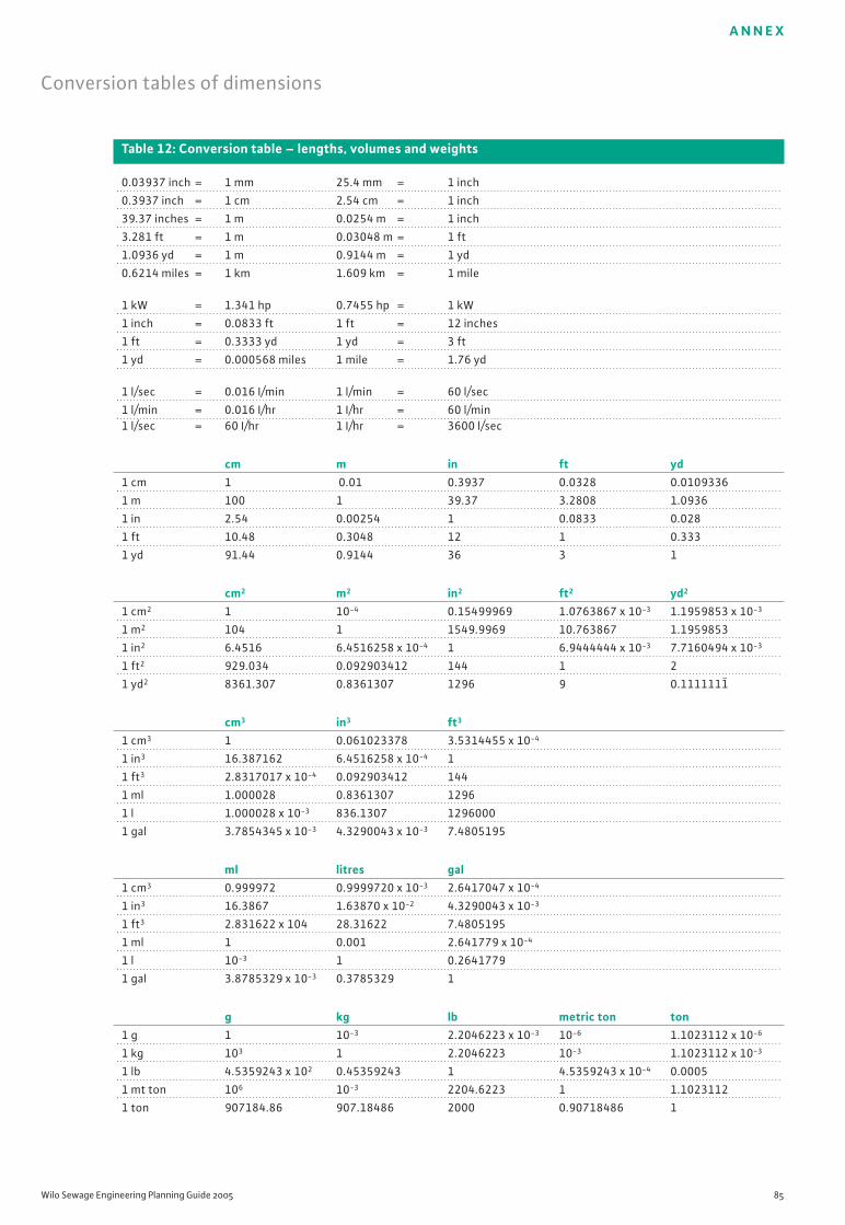
A N N E X
Wilo Sewage Engineering Planning Guide 2005 85
Table 12: Conversion table – lengths, volumes and weights
0.03937 inch = 1 mm 25.4 mm = 1 inch
0.3937 inch = 1 cm 2.54 cm = 1 inch
39.37 inches = 1 m 0.0254 m = 1 inch
3.281 ft = 1 m 0.03048 m = 1 ft
1.0936 yd = 1 m 0.9144 m = 1 yd
0.6214 miles = 1 km 1.609 km = 1 mile
1 kW = 1.341 hp 0.7455 hp = 1 kW
1 inch = 0.0833 ft 1 ft = 12 inches
1 ft = 0.3333 yd 1 yd = 3 ft
1 yd = 0.000568 miles 1 mile = 1.76 yd
1 l/sec = 0.016 I/min 1 l/min = 60 l/sec
1 l/min = 0.016 I/hr 1 I/hr = 60 l/min1 l/sec = 60 I/hr 1 I/hr = 3600 l/sec
cm m in ft yd1 cm 1 0.01 0.3937 0.0328 0.0109336
1 m 100 1 39.37 3.2808 1.0936
1 in 2.54 0.00254 1 0.0833 0.028
1 ft 10.48 0.3048 12 1 0.333
1 yd 91.44 0.9144 36 3 1
cm2 m2 in2 ft2 yd2
1 cm2 1 10-4 0.15499969 1.0763867 x 10⁻³ 1.1959853 x 10⁻³
1 m2 104 1 1549.9969 10.763867 1.1959853
1 in2 6.4516 6.4516258 x 10⁻⁴ 1 6.9444444 x 10⁻³ 7.7160494 x 10⁻³
1 ft2 929.034 0.092903412 144 1 2
1 yd2 8361.307 0.8361307 1296 9 0.1111111–
cm3 in3 ft3
1 cm3 1 0.061023378 3.5314455 x 10⁻⁴
1 in3 16.387162 6.4516258 x 10⁻⁴ 1
1 ft3 2.8317017 x 10⁻⁴ 0.092903412 144
1 ml 1.000028 0.8361307 1296
1 l 1.000028 x 10⁻³ 836.1307 1296000
1 gal 3.7854345 x 10⁻³ 4.3290043 x 10⁻³ 7.4805195
ml litres gal1 cm3 0.999972 0.9999720 x 10⁻³ 2.6417047 x 10⁻⁴
1 in3 16.3867 1.63870 x 10⁻² 4.3290043 x 10⁻³
1 ft3 2.831622 x 10⁴ 28.31622 7.4805195
1 ml 1 0.001 2.641779 x 10⁻⁴
1 l 10-3 1 0.2641779
1 gal 3.8785329 x 10⁻³ 0.3785329 1
g kg lb metric ton ton1 g 1 10-3 2.2046223 x 10⁻³ 10-6 1.1023112 x 10⁻⁶
1 kg 103 1 2.2046223 10-3 1.1023112 x 10⁻³
1 lb 4.5359243 x 10² 0.45359243 1 4.5359243 x 10⁻⁴ 0.0005
1 mt ton 106 10-3 2204.6223 1 1.1023112
1 ton 907184.86 907.18486 2000 0.90718486 1
Conversion tables of dimensions
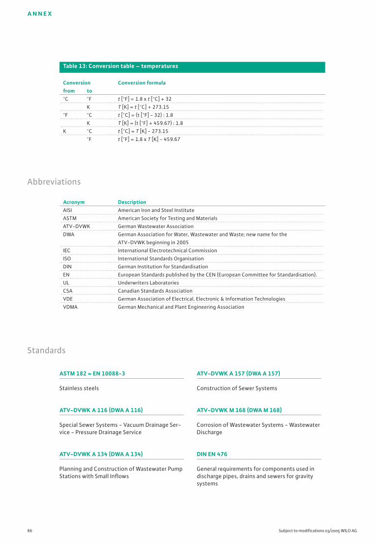
ASTM 182 = EN 10088-3
Stainless steels
ATV-DVWK A 116 (DWA A 116)
Special Sewer Systems - Vacuum Drainage Ser-vice - Pressure Drainage Service
ATV-DVWK A 134 (DWA A 134)
Planning and Construction of Wastewater PumpStations with Small Inflows
A N N E X
86 Subject to modifications 03/2005 WILO AG
Table 13: Conversion table – temperatures
Conversion Conversion formulafrom to°C °F t [°F] = 1.8 x t [°C] + 32
K T [K] = t [°C] + 273.15
°F °C t [°C] = (t [°F] - 32) : 1.8
K T [K] = (t [°F] + 459.67) : 1.8
K °C t [°C] = T [K] - 273.15
°F t [°F] = 1.8 x T [K] - 459.67
Abbreviations
Standards
Acronym DescriptionAISI American Iron and Steel Institute
ASTM American Society for Testing and Materials
ATV-DVWK German Wastewater Association
DWA German Association for Water, Wastewater and Waste; new name for the
ATV-DVWK beginning in 2005
IEC International Electrotechnical Commission
ISO International Standards Organisation
DIN German Institution for Standardisation
EN European Standards published by the CEN (European Committee for Standardisation).
UL Underwriters Laboratories
CSA Canadian Standards Association
VDE German Association of Electrical, Electronic & Information Technologies
VDMA German Mechanical and Plant Engineering Association
ATV-DVWK A 157 (DWA A 157)
Construction of Sewer Systems
ATV-DVWK M 168 (DWA M 168)
Corrosion of Wastewater Systems - WastewaterDischarge
DIN EN 476
General requirements for components used indischarge pipes, drains and sewers for gravitysystems
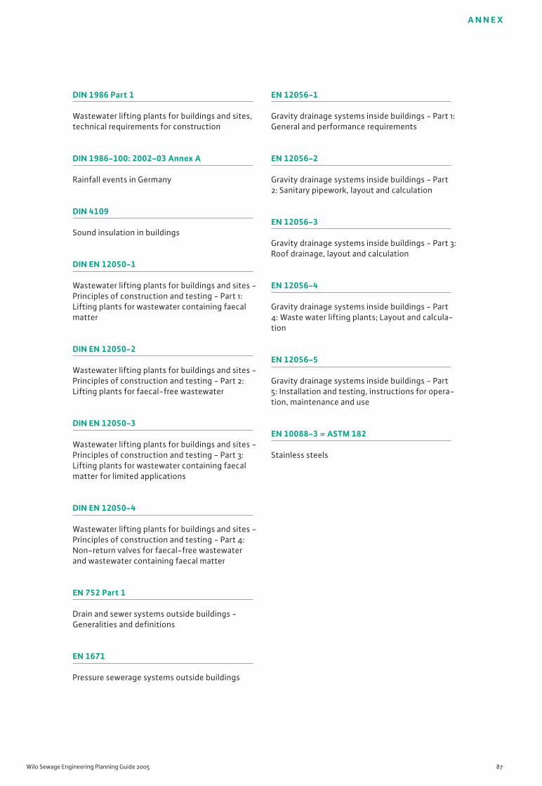
A N N E X
Wilo Sewage Engineering Planning Guide 2005 87
EN 12056-1
Gravity drainage systems inside buildings - Part 1:General and performance requirements
EN 12056-2
Gravity drainage systems inside buildings - Part2: Sanitary pipework, layout and calculation
EN 12056-3
Gravity drainage systems inside buildings - Part 3:Roof drainage, layout and calculation
EN 12056-4
Gravity drainage systems inside buildings - Part4: Waste water lifting plants; Layout and calcula-tion
EN 12056-5
Gravity drainage systems inside buildings - Part5: Installation and testing, instructions for opera-tion, maintenance and use
EN 10088-3 = ASTM 182
Stainless steels
DIN 1986 Part 1
Wastewater lifting plants for buildings and sites,technical requirements for construction
DIN 1986-100: 2002-03 Annex A
Rainfall events in Germany
DIN 4109
Sound insulation in buildings
DIN EN 12050-1
Wastewater lifting plants for buildings and sites -Principles of construction and testing - Part 1:Lifting plants for wastewater containing faecalmatter
DIN EN 12050-2
Wastewater lifting plants for buildings and sites -Principles of construction and testing - Part 2:Lifting plants for faecal-free wastewater
DIN EN 12050-3
Wastewater lifting plants for buildings and sites -Principles of construction and testing - Part 3:Lifting plants for wastewater containing faecalmatter for limited applications
DIN EN 12050-4
Wastewater lifting plants for buildings and sites -Principles of construction and testing - Part 4:Non-return valves for faecal-free wastewaterand wastewater containing faecal matter
EN 752 Part 1
Drain and sewer systems outside buildings -Generalities and definitions
EN 1671
Pressure sewerage systems outside buildings
I N D E X
88 Subject to modifications 03/2005 WILO AG
A
Runoff coefficient C 6, 79Drainage coefficient K 6, 76Abbreviations 86Abrasion 6Sewage generation 6Sewage types 6AISI 14, 15, 16, 21, 28Limited-use plants 8, 74System curve 17Starting current 24Connecting sewer/pipe 17Drain connection value DU 8, 76ATEX, s. Explosion protection 24Installation types 8Buoyancy protection 9Purging discharge pipelines 63
B
Ventilation 9, 63Design rainfall intensity 9, 78Petrol separator 63Concrete 14Operating modes 24Operating time 24Duty point 17Bimetal 26Brackish water 7Bus technology 24
C
Chlorides 11
D
Roof area (effective) 10Seal materials 16DIN 1986 10DIN EN 12050 10Pressure drainage 10Discharge pipeline 17, 74Pressure sensor 27,28Water hammer 17, 66DU value 10Pressure drops 18, 80, 81
E
Stainless steel 1.4301 – V2A 14Stainless steel 1.4404 – V4A 15Operating cycles 84Individual operation 18
Individual run signal 24Individual fault signal 24Electrical conductivity 11EN 12056 11Ventilation 18, 67, 68EPDM 16Ex isolating relay 25Explosion protection 24
F
Lifting plant for wastewater containing faecalmatter 32, 73Downpipe 18Fault diagnostics 67, 68Grease separator 63Flow velocity 13, 14, 18Delivery head 19Fluid 11Delivery rate 19Flow rate 20FPM 16Free (ball) passage 19Gravity drainage line 19
G
Housing materials 16Noise development 11, 13Cast iron 14Ground pipe 19
H
Hardness of water 12Domestic sewage 6
I
Commissioning 73Industrial sewage 7Integrated temperature sensors 26IP protection classes 25
K
Cavitation 21, 22, 67Condensates 7Corrosion 11Costs 9Free (ball) passage 19
Index

I N D E X
Wilo Sewage Engineering Planning Guide 2005 89
L
Impeller types 19, 21Output 25Pipe gradient 21LON (Local Operating Network) 26
M
Sea water 7Minimum gradient 22Minimum nominal diameters 22Combined system 12With effect of wind 10Motor protection 26Motor protection switch 26
N
NBR 16Nominal current 29Nominal diameter 22Nitrates 12Nitrates 12Level measurement system 27, 28Standards 2, 5, 10, 86NPSH 21, 22Usable volume 12
O
Without effect of wind 10Oil separator 63
P
Parallel connection 22HDPE (polyethylene) 15pH value 7, 12Floating normally closed contacts 29PP (polypropylene) 15PT100, PTC 27PUR (polyurethane) 15Sumps, see sump pump stationsPVC (polyvinyl chloride) 15
R
Rainwater 6, 14Rainfall intensity 78Rainwater inflow calculation 10Pipe inner diameter 79, 80, 81Pipeline curve 17, 18Pipe friction losses 82, 83
Series connection 23Backflow level 12Backflow loop 13Backflow protection 13
S
Sand 5, 16Collective run signal 29Collective fault signal 29Sump cover 13Sump design 66Sump pump stations 8, 9, 10, 11, 12, 17, 20, 40,
46, 52, 57, 66, 71, 75, 84Sound insulation 11, 13Operating cycles 12, 23, 84Switching volumes 23Gravity drainage 19, 21Power supply 29Impoundment volume (required) 12Fault signals 29Sulphates 12Sump volume 23
D
Diving bell 28Thermistor 27Thermal overcurrent relay 26Separate system 14
U
Conversion tables 85, 86
V
V2A, V4A 14, 15Losses in pipeline 82, 83Insurance protection 5, 13Viton 16Flow rate 19
W
Maintenance 9, 14, 75Water hardness 14Water consumption figures 77Materials properties 16Materials 14, 15
Z
Zener barrier 29


WILO AG has invested the greatest care into preparing all of the texts in this Planning Guide. Still, the possibility of errors cannot be excluded. The publisher expressly disclaims any and allliability regardless of legal basis.
Copyright 2005 by WILO AG, Dortmund, GermanyThis work and all of its parts are protected by copyright. Any kind of use outside the narrow limits of copyright legislation without the consent of WILO AG is improper and punishable by law.This applies particularly to duplication, copying of individual illustrations, use of excerpts of texts,translation, microfilming, and any other kind of processing, as well as storage and processing inelectronic systems.
First edition 2005
G1 NorthWILO AGHamburg sales agencySinstorfer Kirchweg 74–9221077 Hamburg, GermanyPhone (+49) 40 5559490Fax (+49) 40 55594949
G2 EastWILO AGBerlin sales agencyJuliusstrasse 52–5312051 Berlin-Neukölln, GermanyPhone (+49) 30 6289370Fax (+49) 30 62893770
G3 Saxony/ThuringiaWILO AGDresden sales agencyFrankenring 801723 Kesselsdorf, GermanyPhone (+49) 35204 7050 Fax (+49) 35204 70570
G4 SoutheastWILO AGMunich sales agencyLandshuter Strasse 2085716 Unterschleissheim,GermanyPhone (+49) 89 4200090Fax (+49) 89 42000944
G5 SouthwestWILO AGStuttgart sales agencyHertichstrasse 1071229 Leonberg, GermanyPhone (+49) 7152 94710 Fax (+49) 7152 947141
G6 Rhine-Main:WILO AGFrankfurt sales agencyAn den drei Hasen 3161440 Oberursel/Ts., GermanyPhone (+49) 6171 70460 Fax (+49) 6171 704665
G7 WestWILO AGDüsseldorf sales agencyHans-Sachs-Strasse 440721 Hilden, GermanyPhone (+49) 2103 90920 Fax (+49) 2103 909215
G8 Northwest:WILO AGHannover sales agencyAhrensburger Strasse 130659 Hannover-Lahe, GermanyPhone (+49) 511 438840 Fax (+49) 511 4388444
Central order processing forspecialist wholesalers
WILO AGOrder ProcessingNortkirchenstrasse 10044263 Dortmund, GermanyPhone (+49) 231 4102-0 Fax (+49) 231 4102-7555
The Wilo Team of Experts
–Answers to all of your questions regarding our products, delivery times, shipment, sales prices
–Processing of your orders–Spare parts orders– with
24-hour delivery for all in-stock spare parts
–Mailing informational materials
Phone (+49) 1805R•U•F•W•I•L•O*7•8•3•9•4•5•6
Fax (+49) 231 4102-7666
Available weekdays between 7 a.m. and 6 p.m.
Wilo after-sales service
WILO AGWilo Service CentreNortkirchenstrasse 10044263 Dortmund, Germany
–Your primary contact for after-sales service
–Maintenance and commissioning–Factory repairs–Spare parts advice
Phone (+49) 1805 W•I•L•O•K•D*9•4•5•6•5•3
(+49) 231 4102-7900Fax (+49) 231 4102-7126
Available weekdays between 7 a.m. and 5 p.m., at all othertimes interactive voice responsesystem with call-backguarantee!
Wilo International
AustriaVienna head office:WILO Handelsgesellschaft mbHEitnergasse 131230 ViennaPhone (+43) 1 25062-0Fax (+43) 1 25062-15
Salzburg sales agency:Gnigler Strasse 565020 SalzburgPhone (+43) 662 8716410Fax (+43) 662 878470
Upper Austria sales agency:Trattnachtalstrasse 74710 GrieskirchenPhone (+43) 7248 65051Fax (+43) 7248 65054
SwitzerlandEMB Pumpen AGGerstenweg 74310 RheinfeldenPhone (+41) 61 8368020Fax (+41) 61 8368021
Additional subsidiaries located in:
Belarus, Belgium, Bulgaria, China, Denmark, Finland, France, Greece,Great Britain, Ireland, Italy,Canada, Kazakhstan, Korea,Lebanon, Lithuania, Latvia, The Netherlands, Norway, Poland,Romania, Russia, Sweden, Serbia& Montenegro, Slovakia, Slovenia,Spain, Czech Republic, Turkey,Ukraine, Hungary
You can find their addressesonline at www.wilo.de orwww.wilo.com.
Status: March 2005*12 cents per minute
WILO AG Nortkirchenstrasse 10044263 Dortmund, GermanyPhone (+49) 231 4102-0Fax (+49) 0231 [email protected]
Subject to technical modifications. Our General Terms of Delivery and Service (found at www.wilo.de) shall apply.W 2197/2T/0503/D/PRS
Wilo sales agencies


