11
Sewage Pumps DAS www.masflo.fr
Sewage Pumps DASwww.masflo.fr
APPLICATIONS:
• Pumping of domestic and industrial sewage.• At sewage treatment plants.• Pumping of chemical and industrial waste water.• Pumping of rain water• All kinds of drainage and dewatering work.• Pumping of difficult liquids of industrial processes.
FLUID TYPES:
• Unscreened sewage and other waste water types with high solidsconcentration.
• Water with sand content. Maximum grain size ( 20 - 30 mm). Liquid, sand ratio can be maximum % 6. For higher sand concentrationpreventive provisions must be taken against wear.
• Maximum allowed fluid temperature is 50°C• Maximum allowed medium density is 1,2 gr/cm3, maximum allowed
medium viscosity is 1,5 x 1 o-6 m2/s. Measures must be taken tolower these values. Pump Materials :
• DAS series pumps cannot be used for pumping flammable andexplosive fluids. 1:.i. ....•• ..,. ..
Motor casing - volute casing
Shaft
Pump impeller
Bolts- Nuts
Mechanical seal
Cable
Coating
�
Cast iron GG-20 (EN-JL 1030)
AISI 420
Cast iron GG-25 (EN-JL 1040)
Stainless steel
SIC/SIC - NBR
HO?RN-f
Coal tar epoxy paint over Epoxy primer
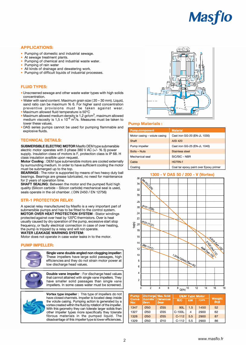
1300 - V DAS 50 I 200 - V (Vortex)
TECHNICAL DETAILS:
SUBMERSIBLE ELECTRIC MOTOR Masflo DEM type submersible electric motor operates with 3 phase 380 V AC(+/-% 5) power supply. Insulation class of motors is F, protection class is IP 68. H class insulation availble upon request. Motor Cooling : DEM type submersible motors are cooled externally by surrounding medium. In order to have sufficient cooling the motor must be submerged up to the top. BEARINGS : The rotor is supported by means of two heavy duty ball bearings. Bearings are grease lubricated, no need for maintenance for 2 years of operation time. SHAFT SEALING: Between the motor and the pumped fluid high quality (Silicon carbide - Silicon carbide) mechanical seal is used, seals operate in the oil chamber. ( DIN 2450 I EN 12756)
STR-1 PROTECTION RELAY:
A special relay manufactured by Masflo is a very important part of submersible pumps and has to be fitted to the control system. MOTOR OVER HEAT PROTECTION SYSTEM : Stator windings protected against over heat by 120°C thermistors. Over is heat usually caused by dry operation of the pump, excessive start stop frequency, or faulty electrical connection in case of over heating, the pump is tripped by a relay and will not operate. WATER LEAKAGE WARNING SYSTEM:
Motor does not operate in case water leaks in to the motor.
PUMP IMPELLER:
Single vane double angled non clogging impeller: These impellers have large solid passages, high efficiencies and they do not strain motor power at low discharge head values.
Double vane impeller : For discharge head values that cannot attained with single vane impellers. They have smaller solid passages than single vane
impellers. In some cases water must be screened.
41--�-+-�-+-�--+-�--+��1--�+-�-+-�-+-�-t
Vortex type impeller : This type of impellers do not have closed channels. Impeller is located deep inside the volute casing. Pumping action is generated by a vortex created within the fluid by rotation of the impeller. With this geometry they can tolerate larger solids than other impeller types more specifically they tolerate fibrous materials in the pumped liquid. The disadvantage of this impeller type is lower efficiencies.
1347
1327
1328
1329
21--�+-�-+-�--+-�--+��f--�+--�+-�-+-�--1
0 2
050
050
050
050
4
035
035
035
010
6 8 Q(l/s) 10 12 14
90L 1.5 1450
C-100L 4 2900
C-112 5.5 2900
C-112 5.5 2900
16
52
62
87
86
18
2 www.masflo.fr

3 www.masflo.fr
4 www.masflo.fr

5 www.masflo.fr

DAS -PARPO SERIES PUMPS DIRECT ONLINE STARTING
CABLE CONNECTION DIAGRAM ( 1,5-5,5 Kw)
�)
STR-1 : PROTECTION RELAY
Terminal Board --t'MJ.���Ll
---------Water leakage electrode
R L1
2 s L2
3 T L3
4
5
6
7
CAUTION:
Masflo warranty is not valid, if pump operates without being connected to STR-1 relay
U1
V1
W1
E2-+-
T1
T2
E
E
T1
T2
15
16
18
A1 (F)
A2 (N)
Water leakage
Termistor contacts
Relay contact leads
Relay coil connections 220V
DAS SERIES PUMPS (Y/A) STAR I DELTA STARTING
CABLE CONNECTION DIAGRAM ( 7,5-11 kW)
�) A2
STR-1: PROTECTION RELAY
-------- Water leakage electrode
R L1 U1
2 s L2 V1
3 T L3 W1
4 R L1 W2
5 s L2 U2
6 T L3 V2
7 E2+
8 T1
9 T2
10 E
6 www.masflo.fr

7 www.masflo.fr

8 www.masflo.fr
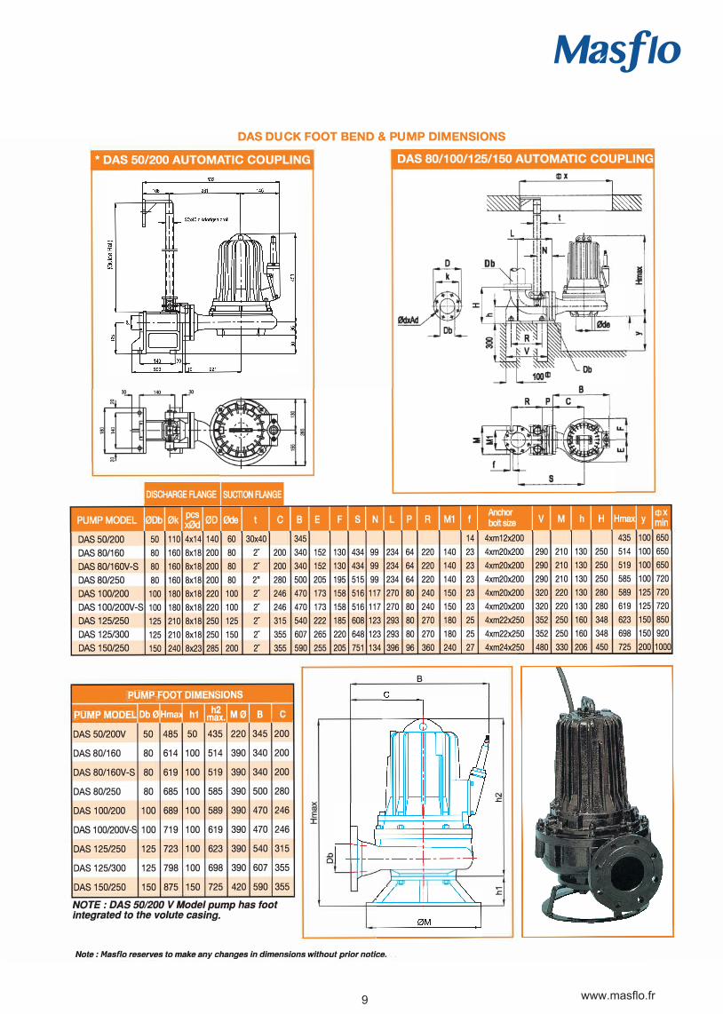
DAS DUCK FOOT BEND & PUMP DIMENSIONS
* DAS 50/200 AUTOMATIC COUPLING DAS 80/100/125/150 AUTOMATIC COUPLING
DISCHARGE FLANGE
DAS 50/200 50 110 4x14 140 60 30x40
DAS 80/160 80 160 8x18 200 80 2" 200
DAS 80/160V-S 80 160 8x18 200 80 2" 200
DAS 80/250 80 160 8x18 200 80 2" 280
DAS 100/200 100 180 8x18 220 100 2" 246
DAS 100/200V-S 100 180 8x18 220 100 2" 246
DAS 125/250 125 210 8x18 250 125 2" 315
DAS 125/300 125 210 8x18 250 150 2" 355
DAS 150/250 150 240 8x23 285 200 2" 355
[:JIII.T.l•Jl,1�tll,',l::l,'l,,,"lltln;)
m11mmm11 ��· h', 1�,,.1,1 •1 :::11 -
DAS 50/200V 50 485 50 435 220 345 200
DAS 80/160 80 614 100 514 390 340 200
DAS 80/160V-S 80 619 100 519 390 340 200
DAS 80/250 80 685 100 585 390 500 280
DAS 100/200 100 689 100 589 390 470 246
DAS 100/200V-S 100 719 100 619 390 470 246
DAS 125/250 125 723 100 623 390 540 315
DAS 125/300 125 798 100 698 390 607 355
DAS 150/250 150 875 150 725 420 590 355
NOTE : DAS 50/200 V Model pump has foot integrated to the volute casing.
345
340 152 130 434 99 234
340 152 130 434 99 234
500 205 195 515 99 234
470 173 158 516 117 270
470 173 158 516 117 270
540 222 185 608 123 293
607 265 220 648 123 293
590 255 205 751 134 396
Note : Masflo reserves to make any changes in dimensions without prior notice.
-�
LL
UJ
14 4xm12x200 435 100 650
64 220 140 23 4xm20x200 290 210 130 250 514 100 650
64 220 140 23 4xm20x200 290 210 130 250 519 100 650
64 220 140 23 4xm20x200 290 210 130 250 585 100 720
80 240 150 23 4xm20x200 320 220 130 280 589 125 720
80 240 150 23 4xm20x200 320 220 130 280 619 125 720
80 270 180 25 4xm22x250 352 250 160 348 623 150 850
80 270 180 25 4xm22x250 352 250 160 348 698 150 920
96 360 240 27 4xm24x250 480 330 206 450 725 200 1000
B
.c
.c
9 www.masflo.fr
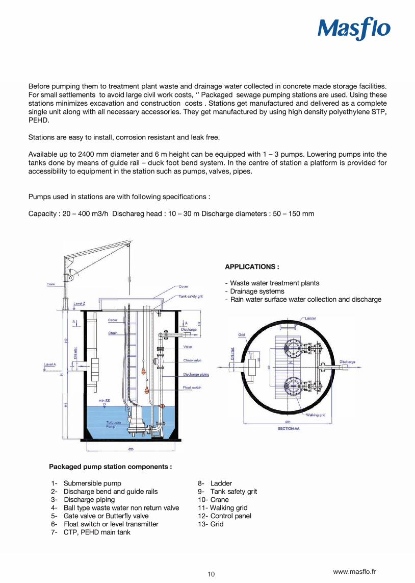
Before pumping them to treatment plant waste and drainage water collected in concrete made storage facilities.
For small settlements to avoid large civil work costs, " Packaged sewage pumping stations are used. Using these stations minimizes excavation and construction costs . Stations get manufactured and delivered as a complete single unit along with all necessary accessories. They get manufactured by using high density polyethylene STP, PEHD.
Stations are easy to install, corrosion resistant and leak free.
Available up to 2400 mm diameter and 6 m height can be equipped with 1 - 3 pumps. Lowering pumps into the
tanks done by means of guide rail - duck foot bend system. In the centre of station a platform is provided for accessibility to equipment in the station such as pumps, valves, pipes.
Pumps used in stations are with following specifications :
Capacity : 20 - 400 m3/h Dischareg head : 1 O - 30 m Discharge diameters : 50 - 150 mm
c, ..
LevelZ
CaOla
Lavef;A
Packaged pump station components :
1- Submersible pump2- Discharge bend and guide rails3- Discharge piping4- Ball type waste water non return valve5- Gate valve or Butterfly valve6- Float switch or level transmitter7- CTP, PEHD main tank
APPLICATIONS :
- Waste water treatment plants- Drainage systems- Rain water surface water collection and discharge
Valve
Float $WllCII
8- Ladder9- Tank safety grit10- Crane11- Walking grid12- Control panel13- Grid
00
SECT10N-M
10 www.masflo.fr

INTERNATIONAL PUMPING SYSTEM - IPS PUMP
118 Avenue de Stalingrad - 92700 Colombes - France
Tel : +33 4 91 92 01 18 Fax: +33 4 91 98 11 30
Web: www.masflo.fr Contact : [email protected]


