44
© Panasonic Industrial Devices SUNX Co., Ltd. 2016 MJE-SFBHC No.0056-14V FUNCTION - CANCEL ENTER + INSTRUCTION MANUAL Handy Controller Exclusive for SF4B / SF4B<V2> Series SFB-HC Ver.2.1
© Panasonic Industrial Devices SUNX Co., Ltd. 2016 MJE-SFBHC No.0056-14V
FUNCTION
-
CANCEL
ENTER
+
INSTRUCTION MANUALHandy Controller Exclusive for SF4B / SF4B<V2> Series
SFB-HC Ver.2.1

1 © Panasonic Industrial Devices SUNX Co., Ltd. 2016
(MEMO)

2© Panasonic Industrial Devices SUNX Co., Ltd. 2016
Thank you for purchasing Panasonic Industrial Devices SUNX’s Handy Controller SFB-HC (Ver. 2.1) exclusive for SF4B / SF4B<V2> series.Please read both the instruction manual of this manual and SF4B / SF4B<V2> series or SF-C14EX carefully and thoroughly for the correct and optimum use of this device.Kindly keep this manual in a convenient place for quick reference.
This manual has been written for the following personnel who have undergone suitable training and have knowledge of light curtains, as well as, safety systems and standards (ANSI, etc.).
● who are responsible for the introduction of this device ● who design a system using this device ● who install and connect this device ● who manage and operate a plant using this device
1) All the contents of this instruction manual are the copyright of the publishers, and may not be reproduced (even extracts) in any form by any electronic or mechanical means (including photocopying, recording, or information storage and retrieval) without permission in writing from the publisher.
2) The contents of this instruction manual may be changed without prior notice for further im-provement of the device.
3) A part of / all of this instruction manual or the software may not be copied without permission from the publisher.
4) Though we have carefully drawn up the contents of this instruction manual, if there are any aspects that are not clear, or any error that you may notice, please contact our local Pana-sonic Industrial Devices SUNX office or the nearest distributor.
5) We shall not be responsible for any consequences of use regardless of the descriptions above.
NOTICE

3 © Panasonic Industrial Devices SUNX Co., Ltd. 2016
Contents
CHAPTER 1 INTRODUCTION ..............................................................................41-1 Attention Marks .....................................................................................................41-2 Safety Precautions ................................................................................................4
CHAPTER 2 GENERAL OUTLINE .......................................................................62-1 Features ................................................................................................................62-2 Part Descriptions ..................................................................................................62-3 Connecting / Setting Procedures .......................................................................... 7
2-3-1 When Using with Light Curtain SF4B / SF4B<V2> Series Only ........................72-3-2 When Using in Combination with Application Expansion Unit SF-C14EX ......... 9
CHAPTER 3 FUNCTIONS ....................................................................................113-1 Functional Descriptions <When Using with Light Curtain SF4B / SF4B<V2> Series Only> . 11
3-1-1 Fixed Blanking Function.....................................................................................113-1-2 Floating Blanking Function.................................................................................123-1-3 Auxiliary Output Switching Function...................................................................133-1-4 Emission Intensity Control Function...................................................................143-1-5 Copy Function ....................................................................................................143-1-6 Muting Setting Changing Function .....................................................................143-1-7 Interlock Setting Changing Function ..................................................................153-1-8 External Device Monitor Setting Changing Function .........................................153-1-9 Protective Function ............................................................................................163-1-10 Initialization Function .......................................................................................163-1-11 Setting Contents Monitoring Function ..............................................................163-1-12 Override Setting Changing Function (Ver. 2.1 only) ........................................16
3-2 Functional Descriptions <When Using in Combination with Application Expansion Unit SF-C14EX> ................................................................................. 17
3-2-1 Fixed Blanking Function.....................................................................................173-2-2 Floating Blanking Function.................................................................................183-2-3 Auxiliary Output Switching Function...................................................................193-2-4 Emission Intensity Control Function...................................................................203-2-5 Copy Function ....................................................................................................203-2-6 Muting Setting Changing Function .....................................................................203-2-7 Interlock Setting Changing Function ..................................................................213-2-8 External Device Monitor Setting Changing Function .........................................213-2-9 Protective Function ............................................................................................213-2-10 Initialization Function .......................................................................................223-2-11 Setting Contents Monitoring Function ..............................................................223-2-12 Override Setting Changing Function (Ver. 2.1 only) ........................................22
3-3 Function Setting (Operation Procedure) ............................................................... 233-3-1 Fixed Blanking Function.....................................................................................263-3-2 Floating Blanking Function.................................................................................273-3-3 Auxiliary Output Switching Function...................................................................283-3-4 Emission Intensity Control Function...................................................................293-3-5 Copy Function ....................................................................................................303-3-6 Muting Setting Changing Function .....................................................................313-3-7 Interlock Setting Changing Function ..................................................................333-3-8 External Device Monitor Setting Changing Function .........................................343-3-9 Protective Function ............................................................................................353-3-10 Initialization Function .......................................................................................363-3-11 Setting Contents Monitoring Function ..............................................................373-3-12 Override Setting Changing Function (Ver. 2.1 only) ........................................38
CHAPTER 4 TROUBLESHOOTING .....................................................................39CHAPTER 5 SPECIFICATIONS / DIMENSIONS ..................................................40
5-1 Specifications ........................................................................................................405-2 Dimensions ...........................................................................................................40

4© Panasonic Industrial Devices SUNX Co., Ltd. 2016
CHAPTER 1 INTRODUCTION
1-1 Attention MarksThis instruction manual employs the following attention marks , depending on the degree of the danger to call operator’s attention to each particular action. Read the following expla-nation of these marks thoroughly and observe these notices without fail.Besides, the attention mark is prepared for the helpful information, detail instruction related to each part, and reference item or page.
If you ignore the advice with this mark, death or serious injury could result.
If you ignore the advice with this mark, injury or material damage could result.
Remarks The supplementary content is described with this mark.
REFERENCE The related content is described with this mark.
1-2 Safety Precautions ■ Use this device as per its specifications. Do not modify this device since its functions and capa-bilities may not be maintained and it may malfunction.
■ This device has been developed / produced for industrial use only. ■ Before using this device, check whether the device performs properly with the functions and ca-pabilities as per the design specifications.
■ This device cannot be used for a SF4B-□01<V2> and SF-C14EX-01. ■ In case of disposal, dispose this device as industrial waste.
♦ User in charge ● The user in charge has responsible to indicate the person to take the training required for the safety system, using method, installation, operation, and maintenance.
● This device is used and managed by the specialist, never use this device by other operator.
♦ Specialist ● A person who is appropriately educated, has widespread knowledge and experience, and can solve various problems which may arise during work.
♦ Operator ● The operator should read this instruction manual thoroughly, understand its contents, and perform operations following the procedures described in this manual, for the correct operation of this device.
● In case this device does not perform properly, the operator should report this to the person in charge and stop the machine operation immediately. The machine must not be operated until correct performance of this device has been confirmed.

5 © Panasonic Industrial Devices SUNX Co., Ltd. 2016
♦ Fixed blanking function, floating blanking function ● With the fixed blanking function, this device prevents the person or object from entering into the dangerous parts of the machine through the invalid sensing area. However, even though this device can prevent the interference of the person or object into the invalid sensing area with the fixed blanking function, there might exist the more space between the SF4B / SF4B<V2> series and already-existence object. Therefore, set the protecting structure so as not to exist any space in the dangerous sensing area. Detecting human body in the sensing area could result in death or serious injury.
● With the floating blanking function, this device changes the size of the minimum sensing ob-ject of the SF4B / SF4B<V2> series that is pre-set the function. When setting or changing the function, calculate and measure the safety distance again, and check that the device has the wider space than the safety distance between the dangerous parts of the machine and the sensing area of the SF4B / SF4B<V2> series. If the sufficient distance is not main-tained, the machine will not stop before its dangerous parts are reached, which can result in death or serious injury.
● Set and change the function of the device following the relative laws, regulation, and stan-dard without fail.
♦ Muting setting changing function ● The muting setting changing function temporarily invalidates safety function of the connected devices. Confirm all of the applied laws and standards, and install or operate this device and peripheral devices correctly. Failure to do so, the operator may suffer a serious injury.
♦ Environment ● Do not use a mobile phone or a radio phone near this device. ● Do not use this device in the following environments.1) Areas with high humidity where condensation is likely to occur2) Areas exposed to corrosive or explosive gases3) Areas exposed to vibration or shock of levels higher than that specified4) Areas exposed to contact with water5) Areas exposed to too much steam or dust
♦ Wiring ● Be sure to carry out the wiring in the power supply OFF condition. ● All electrical wiring should conform to the regional electrical regulations and laws. The wiring should be done by engineer(s) having the special electrical knowledge.
● Do not run the wires together with high-voltage lines or power lines or put them in the same raceway. This can cause malfunction due to induction.
♦ Maintenance ● Clean this device with a clean cloth. Do not use any volatile chemicals.
♦ Other ● Never reassemble or remodel this device.
INTRODUCTION

6© Panasonic Industrial Devices SUNX Co., Ltd. 2016
CHAPTER 2 GENERAL OUTLINE
This chapter gives the system construction, part description, etc. of this device.
2-1 FeaturesThis device is the handy controller for setting each function of the light curtain SF4B / SF4B<V2> series and the application expansion unit SF-C14EX.Besides, this device performs the checking and copying the setting contents of the func-tion, and protection of writing.<Functions>
● Fixed blanking function ● Floating blanking function ● Auxiliary output switching function ● Emission intensity control function ● Copy function ● Muting setting changing function ● Interlock setting changing function ● External device monitor setting changing function ● Protective function ● Initialization function ● Setting contents monitoring function ● Override setting changing function
2-2 Part Descriptions
FUNCTION
-
CANCEL ENTER
+
Male connector
Cable (0.5m)
FUNCTION indicator × 9(Green)FUNCTION switch
Digital display (Red)
+ switch
ENTER switchCANCEL switch
- switch
Female connector

7 © Panasonic Industrial Devices SUNX Co., Ltd. 2016
Connecting / Setting Procedures
2-3 Connecting / Setting ProceduresThis section describes the connecting / setting procedures for both this device and SF4B / SF4B<V2> series or SF-C14EX.
2-3-1 When Using with Light Curtain SF4B / SF4B<V2> Series Only<When using the 8-core cable>1. Set the SF4B / SF4B<V2> series, and
check that the SF4B / SF4B<V2> series works properly. For mounting method of SF4B / SF4B<V2> series, refer to the re-spective Instruction Manuals.
2. Turn OFF the power, and disconnect the ex-tension cable with connectors connected to SF4B / SF4B<V2> series, and then connect this device between SF4B / SF4B<V2> se-ries (emitter or receiver) and the extension cable with connectors.
Bottom cap cable
SF4B / SF4B<V2> series
Extension cable with connectorsTo power supply
FUNCTION
-
CANCEL
ENTER
+
Bottom cap cable
SF4B / SF4B<V2> series(Emitter or receiver)
Extension cable with connectors
To power supply
This device
3. Turn ON the power, and set the function with this device. After the power of this device is ON, approx. 30 sec. will be taken for data transmission with SF4B
/ SF4B<V2> series. While data transmission, “ ” lights up in revolving.The control output (OSSD 1 / 2) of SF4B / SF4B<V2> series is set to “OFF” while this device has been connected.
REFERENCE Refer to “3-1 Functional Descriptions <When Using with Light Curtain SF4B / SF4B<V2> Series Only>” for the details of the functions, and refer to “3-3 Function Set-ting (Operation Procedure)” for the setting procedures of the functions respectively.
4. Turn OFF the power, then remove this device.5. Connect both SF4B / SF4B<V2> series and the extension cable with connectors and return the
device to the state described in procedure 1.6. Check that the SF4B / SF4B<V2> series works as set at the procedure 3. Then, inspect the SF4B / SF4B<V2> series.
REFERENCE Refer to “Chapter 4 Maintenance” of the SF4B / SF4B<V2> series instruction manual for the details of the inspection of the SF4B / SF4B<V2> series.

8© Panasonic Industrial Devices SUNX Co., Ltd. 2016
Connecting / Setting Procedures
<When using the 12-core cable>When the connection cable for the muting function, the conversion cable SFB-CCJ02-HC (accessory) is used.1. Set the SF4B / SF4B<V2> series, and
check that the SF4B / SF4B<V2> series works properly. For mounting method of SF4B / SF4B<V2> series, refer to the re-spective Instruction Manuals.
2. Turn OFF the power, and disconnect the ex-tension cable with connectors connected to SF4B / SF4B<V2> series, and then connect this device and SFB-CCJ02-HC between the SF4B / SF4B<V2> series (emitter or receiver) and the extension cable with con-nectors.
FUNCTION
-
CANCEL
ENTER
+
Bottom cap cable
SF4B / SF4B<V2> series(Emitter or receiver)
Extension cable with connectors
To power supply
This device
Conversion cableSFB-CCJ02-HC (Accessory)
Bottom cap cable
SF4B / SF4B<V2> series
Extension cable with connectorsTo power supply
3. Turn ON the power, and set the function with this device. After the power of this device is ON, approx. 30 sec. will be taken for data transmission with SF4B
/ SF4B<V2> series. While data transmission, “ ” lights up in revolving.The control output (OSSD 1 / 2) of SF4B / SF4B<V2> series is set to “OFF” while this device has been connected.
REFERENCE Refer to “3-1 Functional Descriptions <When Using with Light Curtain SF4B / SF4B<V2> Series Only>” for the details of the functions, and refer to “3-3 Function Set-ting (Operation Procedure)” for the setting procedures of the functions respectively.
4. Turn OFF the power, then remove this device and SFB-CCJ02-HC.5. Connect both SF4B / SF4B<V2> series and the extension cable with connectors and return the
device to the state described in procedure 1.6. Check that the SF4B / SF4B<V2> series works as set at the procedure 3. Then, inspect the SF4B / SF4B<V2> series.
REFERENCE Refer to “Chapter 4 Maintenance” of the SF4B / SF4B<V2> series instruction manual for the details of the inspection of the SF4B / SF4B<V2> series.

9 © Panasonic Industrial Devices SUNX Co., Ltd. 2016
Connecting / Setting Procedures
2-3-2 When Using in Combination with Application Expansion Unit SF-C14EX<The 8-core cable is used>1. Set the SF4B / SF4B<V2> series and
SF-C14EX, and check that the SF4B / SF4B<V2> series works properly. For mounting method of SF4B / SF4B<V2> series or SF-C14EX, refer to the respective Instruction Manuals.
2. Turn OFF the power, and disconnect the ex-tension cable with connectors connected to the emitter side (or receiver side) of SF4B / SF4B<V2> series from SF-C14EX, and then connect the emitter side (or receiver side) of this device to the receiver side (or emitter side) connector of SF-C14EX.
FUNCTION
-
CANCEL
ENTER
+
Bottom cap cable
SF4B / SF4B<V2> series(Emitter or receiver)
SF-C14EX
SF4B / SF4B<V2> series(Receiver or emitter)
This device
3. Turn ON the power, and set the function with this device. After the power of this device is ON, a total approx. 30 sec. will be taken for data transmission with
SF4B / SF4B<V2> series and SF-C14EX. While data transmission, “ ” lights up in revolving. [The safety output 1 / 2 of SF-C14EX series are set to “OFF” while this device has been connected.]
REFERENCE Refer to “3-2 Functional Descriptions <When Using in Combination with Application Expansion Unit SF-C14EX>” for the details of the functions, and refer to “3-3 Function Setting (Operation Procedure)” for the setting procedures of the functions respectively.
4. Turn OFF the power, and remove this device.5. Connect the SF4B / SF4B<V2> series and SF-C14EX, and return the device to the state de-
scribed in procedure 1.6. Check that the SF4B / SF4B<V2> series works as set at the procedure 3. Then, inspect the SF4B / SF4B<V2> series.
REFERENCE Refer to “Chapter 4 Maintenance” of the SF4B / SF4B<V2> series instruction manual for the details of the inspection of the SF4B / SF4B<V2> series.
Bottom cap cable
SF4B / SF4B<V2> series
Extension cable with connectors
SF-C14EX

10© Panasonic Industrial Devices SUNX Co., Ltd. 2016
Connecting / Setting Procedures
<In case this device cannot be connected between SF4B / SF4B<V2> series and the connecting cable> ● This device can be connected to SF4B / SF4B<V2> series by using the connection cable with a connector on one end (optional).
<For PNP output> <For NPN output>
● Connection cable with a connector on one end: 2 pcs./setModel No. Cable length Description
SFB-CC3 3mFor 8-core cableSFB-CC10 10m
SFB-CC3-MU 3mFor 12-core cableSFB-CC10-MU 10m
• The setting procedure remains the same.• The control output (OSSD 1 / 2) of SF4B / SF4B<V2> series is set to “OFF” while this de-
vice has been connected. (The safety output 1 / 2 of SF-C14EX is also set to “OFF” while SF-C14EX has been used.) Once the setting is completed, turn OFF the power, remove this de-vice and then turn ON the power again.
Connecting cable with a connector on one end
24V±10% +-
Connecting cable with a connector on one end
This device
Em
itter
Rec
eive
r
(Shi
eld)
(Blu
e)
(Bro
wn)
(Ora
nge)
(Ora
nge
/ Bla
ck)
(Shi
eld)
(Blu
e)
(Bro
wn)
(Ora
nge)
(Ora
nge
/ Bla
ck)
(Shi
eld)
(Blu
e)
(Bro
wn)
(Ora
nge)
(Oran
ge / B
lack)
Connecting cable with a connector on one end
24V±10% +-
Connecting cable with a connector on one end
This device
Em
itter
Rec
eive
r
(Shi
eld)
(Blu
e)
(Bro
wn)
(Ora
nge)
(Ora
nge
/ Bla
ck)
(Shi
eld)
(Blu
e)
(Bro
wn)
(Ora
nge)
(Ora
nge
/ Bla
ck)
(Shi
eld)
(Blu
e)
(Bro
wn)
(Ora
nge)
(Oran
ge / B
lack)

11 © Panasonic Industrial Devices SUNX Co., Ltd. 2016
CHAPTER 3 FUNCTIONS
If configuration of the system is changed (change of the SF-C14EX to be used / not to be used, replace the SF4B / SF4B<V2> series etc.), set the function again.
3-1-1 Fixed Blanking FunctionThis is a function that the control output (OSSD 1 / 2) of SF4B / SF4B<V2> series is not turned OFF, even if the specified beam channel(s) is blocked OFF.This is useful when an obstacle always blocks OFF the specific beam channel(s).There are “Clear,” “Auto” and “Manual” for the setting method.
● Clear setting : The fixed blanking function is to be invalid (factory setting). ● Auto setting : The currently blocked OFF beam channels are set as “effective beam channels”
in the fixed blanking function. Be sure to set this function in the state where the emitter emits light. Furthermore, this function cannot be set in the state where all beam channels receive lights / are blocked.
● Manual setting : Each beam channel can be set to “effective / ineffective” in the fixed blanking function respectively.
3-1 Functional Descriptions <When Using with Light Curtain SF4B / SF4B<V2> Series Only>
This section describes each function when using with SF4B / SF4B<V2> series only.When using with SF-C14EX, refer to “3-2 Functional Descriptions <When Using in Combina-tion with Application Expansion Unit SF-C14EX>.”
When the fixed blanking function is used, the control output (OSSD 1 / 2) of SF4B / SF4B<V2> series is not turned OFF even if the particular beam channels are blocked.By using a protection structure etc., make the dangerous parts of the machine inaccessible to personnel through the sensing area of the particular beam channels.
<Before measures>
<After measures>
Obstacle
Dangerous area
Protection structure
Beam channels the fixed blank-ing function has been set to ON
Beam channels the fixed blank-ing function has been set to ON
Em
itter
Rec
eive
r
Em
itter
Rec
eive
r
When the effective beam channel(s) in the fixed blanking function receive(s) the beam(s) from the emitter, the control output (OSSD 1 / 2) of the SF4B / SF4B<V2> series is fixed to “OFF.” In this case, check the mounting condition and turn the power ON again.(Even if the power is turned ON again, the fixed blanking function still stays effective.)When the fixed blanking function is used, the received light intensity indicator of SF4B / SF4B<V2> series is turned OFF regardless of the received light intensity.
12© Panasonic Industrial Devices SUNX Co., Ltd. 2016
Functional Descriptions
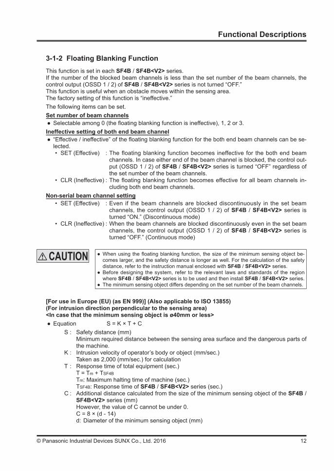
3-1-2 Floating Blanking FunctionThis function is set in each SF4B / SF4B<V2> series.If the number of the blocked beam channels is less than the set number of the beam channels, the control output (OSSD 1 / 2) of SF4B / SF4B<V2> series is not turned “OFF.”This function is useful when an obstacle moves within the sensing area.The factory setting of this function is “ineffective.”The following items can be set.Set number of beam channels
● Selectable among 0 (the floating blanking function is ineffective), 1, 2 or 3.Ineffective setting of both end beam channel
● “Effective / ineffective” of the floating blanking function for the both end beam channels can be se-lected.• SET (Effective) : The floating blanking function becomes ineffective for the both end beam
channels. In case either end of the beam channel is blocked, the control out-put (OSSD 1 / 2) of SF4B / SF4B<V2> series is turned “OFF” regardless of the set number of the beam channels.
• CLR (Ineffective) : The floating blanking function becomes effective for all beam channels in-cluding both end beam channels.
Non-serial beam channel setting• SET (Effective) : Even if the beam channels are blocked discontinuously in the set beam
channels, the control output (OSSD 1 / 2) of SF4B / SF4B<V2> series is turned “ON.” (Discontinuous mode)
• CLR (Ineffective) : When the beam channels are blocked discontinuously even in the set beam channels, the control output (OSSD 1 / 2) of SF4B / SF4B<V2> series is turned “OFF.” (Continuous mode)
[For use in Europe (EU) (as EN 999)] (Also applicable to ISO 13855)(For intrusion direction perpendicular to the sensing area)<In case that the minimum sensing object is ø40mm or less>
● Equation S = K × T + CS : Safety distance (mm) Minimum required distance between the sensing area surface and the dangerous parts of
the machine.K : Intrusion velocity of operator’s body or object (mm/sec.) Taken as 2,000 (mm/sec.) for calculationT : Response time of total equipment (sec.) T = Tm + TSF4B Tm: Maximum halting time of machine (sec.) TSF4B: Response time of SF4B / SF4B<V2> series (sec.)C : Additional distance calculated from the size of the minimum sensing object of the SF4B /
SF4B<V2> series (mm) However, the value of C cannot be under 0. C = 8 × (d - 14) d: Diameter of the minimum sensing object (mm)
● When using the floating blanking function, the size of the minimum sensing object be-comes larger, and the safety distance is longer as well. For the calculation of the safety distance, refer to the instruction manual enclosed with SF4B / SF4B<V2> series.
● Before designing the system, refer to the relevant laws and standards of the region where SF4B / SF4B<V2> series is to be used and then install SF4B / SF4B<V2> series.
● The minimum sensing object differs depending on the set number of the beam channels.

13 © Panasonic Industrial Devices SUNX Co., Ltd. 2016
Functional Descriptions
<Minimum sensing object>Floating blanking function
IneffectiveEffective
1 beam channel 2 beam channels 3 beam channelsSF4B-F□, SF4B-F□<V2> ø14mm ø24mm ø34mm ø44mmSF4B-H□, SF4B-H□<V2> ø25mm ø45mm ø65mm ø85mmSF4B-A□, SF4B-A□<V2> ø45mm ø85mm ø125mm ø165mm
3-1-3 Auxiliary Output Switching FunctionThis function changes the operation state of the auxiliary output. It is useful when desired to make an indicator to operate or inform the operation state of the SF4B / SF4B<V2> series to PLC.
The following settings are selectable.
Setting mode Auxiliary output setting
Operation of the auxiliary output corresponding to SF4B / SF4B<V2> series state
Emission halt
State of sensing area when emitting
LockoutUnshielded
ShieldedUnstable light-receiving condition
Others
0Negative logic of the control output (OSSD 1 / 2)(factory setting)
ON OFF when OSSD is ONON when OSSD is OFF ON
1 Positive logic of the control output (OSSD 1 / 2) OFF ON when OSSD is ON
OFF when OSSD is OFF OFF
2 ON when emitting OFF ON OFF3 OFF when emitting ON OFF ON
4 OFF under unstable lightreceiving condition (Note 1) (Note 3) OFF ON (Note 3) (Note 3)
5 ON under unstable lightreceiving condition (Note 1) (Note 3) ON OFF (Note 3) (Note 3)
6 ON during muting OFF ON during mutingOthers: OFF OFF
7 OFF during muting ON OFF during mutingOthers: ON ON
8 ON in light receiving condition(Note 2) OFF ON OFF OFF
9 OFF in light receiving condition(Note 2) ON OFF ON ON
Notes: 1) When the fixed blanking function, the floating blanking function or the muting function is used, the setting of ON / OFF under unstable light-receiving condition does not work.
2) By the setting of ON / OFF in light receiving condition, light-receiving / light interrupted condition is output regardless of the fixed blanking function, the floating blanking function or the muting function.
<e.g.> When the fixed blanking function is used, if an obstacle exists in the set area and other area is in light receiving con-
dition, the control output (OSSD 1 / 2) is in ON sate, however, the auxiliary output becomes OFF since the SF4B / SF4B<V2> series has been detecting the obstacle.
3) The state of the auxiliary output remains the same even if the SF4B / SF4B<V2> series state changes.
If the floating blanking function is used, the incident light intensity indicator is turned OFF when an obstacle exists in the sensing range regardless of the incident light intensity.
Do not use the auxiliary output for the purpose of stopping the machine in which the SF4B / SF4B<V2> series is installed. Failure to do so could result in death or serious injury.

14© Panasonic Industrial Devices SUNX Co., Ltd. 2016
Functional Descriptions
3-1-4 Emission Intensity Control FunctionThis function reduces the emitting intensity.It is useful for preventing interference from the emitter to the other devices.Emission intensity control
• CLR (Ineffective) : Operating range is 0.3 to 9m for SF4B-H□ / SF4B-H□<V2> (12 to 64 beam channels) and SF4B-A□ / SF4B-A□<V2> (6 to 32 beam channels), 0.3 to 7m for SF4B-F□ / SF4B-F□<V2> and SF4B-H□ / SF4B-H□<V2> (72 to 96 beam channels) and SF4B-A□ / SF4B-A□<V2> (36 to 48 beam channels) (factory setting).
• SET (Effective) : The operating range is reduced by approx. 50%.
3-1-5 Copy FunctionThis is a function to copy the setting of a SF4B / SF4B<V2> series to other SF4B / SF4B<V2> series.This function is available only under the same system configuration (the number of sensors, the num-ber of beam channels, same model No.).All functions that are settable with this device can be copied.Note that the password is also copied with this function.The following operations are available with this function.
● Upload : Upload the functional setting data of SF4B / SF4B<V2> series to this device. ● Download : Download the functional setting data of this device to SF4B / SF4B<V2> series. ● Monitoring : Check the functional setting data saved in this device.
This device
SF4B / SF4B<V2> seriesCopied
SF4B / SF4B<V2> seriesCopied
SF4B / SF4B<V2> seriesOriginal
Upload Download(Storage area for SF4B / SF4B<V2> series)
3-1-6 Muting Setting Changing FunctionThe setting of the muting function can be changed.Setting of the muting function on each beam channel
● Each beam channel can be set to “effective / ineffective” in the muting function respectively. (Note) ● The factory setting of this function is effective for all beam channels.
Note: If the beam channel set to ineffective in the muting function is blocked, the control output (OSSD 1 / 2) becomes “OFF” and the muting function is canceled.
● There are two setting methods, “Auto” and “Manual” to set muting beam channel.• Auto setting : The beam channel which is currently blocked is set as the “effective” beam
channel. When all beam channels are in light receiving condition, the setting is not accepted. Furthermore, in the state where emission is halted or all beam channels are blocked, the all beam channels become “effective” in the muting function.
• Manual setting : Each beam channel can be set to “effective / ineffective” in the muting function.ON: The muting function is effectiveOFF: The muting function is ineffective

15 © Panasonic Industrial Devices SUNX Co., Ltd. 2016
Functional Descriptions
Muting input conditions ● The order for inputting the muting input A and B, which the muting function activates, can be set.A = b: Effective even either comes firstA b: Effective only when the input A comes firstb A: Effective only when the input B comes first
Note: The setting is possible for each channel.
Setting of the muting lamp diagnosis function (Ver. 2 or later) ● The muting lamp diagnosis function can be set to “effective / ineffective.” (Note)The factory setting of this function is effective.ON : The muting lamp diagnosis function is effective.OFF : The muting lamp diagnosis function is ineffective.
Note: If the muting lamp diagnosis function is set to ineffective, the muting function is maintained even if the lamp blew.
Muting sensor output operation setting (Ver. 2.1 only) ● Output operation of the muting sensor can be selected.The factory setting is NONO (Normally Open, Normally Open).• NONO (Normally Open, Normally Open)
A muting sensor which is to be connected to the muting input A (ON with light non-received sta-tus, ON with object approaching status and ON with object contacted status) A muting sensor which is to be connected to the muting input B (ON with light non-received sta-tus, ON with object approaching status and ON with object contacted status)
• NONC (Normally Open, Normally Closed)A muting sensor which is to be connected to the muting input A (ON with light non-received sta-tus, ON with object approaching status and ON with object contacted status) A muting sensor which is to be connected to the muting input B (ON with light received status, ON with object non-approaching status and ON with object non-contacted status)
3-1-7 Interlock Setting Changing FunctionOne condition can be selected from the following three interlock conditions. It can be set to invalid, too. (Mode 3)
• Start / Restart interlock (Mode 0)The SF4B / SF4B<V2> series goes into interlock condition after the power is ON and when it is in the light receiving condition.
The factory setting is Start / Restart interlock.• Start interlock (Mode 1)
The SF4B / SF4B<V2> series goes into interlock condition only when the power is ON. Once the SF4B / SF4B<V2> series is reset, it does not go into interlock condition again.
• Restart interlock (Mode 2)The SF4B / SF4B<V2> series does not go into the interlock condition when the power is ON. The SF4B / SF4B<V2> series goes into interlock condition only when the SF4B / SF4B<V2> series receives the light, after the power is ON, the control output (OSSD 1 / 2) is turned into ON once and then the SF4B / SF4B<V2> series is blocked.
3-1-8 External Device Monitor Setting Changing FunctionThe setting of the external device monitor can be changed.1. Allowable period of the response time: 100 to 600ms (unit of 10ms) The factory setting is 300ms.2. “Effective / ineffective” of the external device monitor function can be selected. The factory setting is “effective.”

16© Panasonic Industrial Devices SUNX Co., Ltd. 2016
Functional Descriptions
3-1-9 Protective FunctionThe functional settings are not allowed to change without the input of a password.When the protective function is set to “effective,” the setting can be changed by inputting the password.The setting contents monitor function can be used regardless of the protective function “effective / ineffective.”The password should be a 4-digit number from 0 to 9. (The password of the factory setting is “0000.”)The protective function is set on the receiver side.
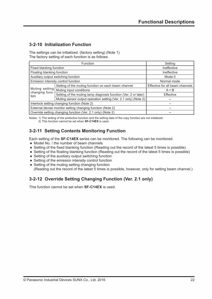
3-1-10 Initialization FunctionThe settings can be initialized. (factory setting) (Note)The factory setting of each function is as follows.
Function SettingFixed blanking function IneffectiveFloating blanking function IneffectiveAuxiliary output switching function Mode 0Emission intensity control function Normal mode
Muting setting changing func-tion
Setting of the muting function on each beam channel Effective for all beam channelsMuting input conditions A = BSetting of the muting lamp diagnosis function (Ver. 2 or later) EffectiveMuting sensor output operation setting (Ver. 2.1 only) NONO
Interlock setting changing function Start / RestartExternal devise monitor setting changing function Effective / 300msOverride setting changing function (Ver. 2.1 only) 60 sec.
Note: The setting of the protective function and the setting data of the copy function are not initialized.
3-1-11 Setting Contents Monitoring FunctionEach setting of the SF4B / SF4B<V2> series can be monitored. The following can be monitored.
● Model No. / the number of beam channels ● Setting of the fixed blanking function (Reading out the record of the latest 5 times is possible) ● Setting of the floating blanking function (Reading out the record of the latest 5 times is possible) ● Setting of the auxiliary output switching function ● Setting of the emission intensity control function ● Setting of the muting setting changing function(Reading out the record of the latest 5 times is possible, however, only for setting beam channel.)
● Setting of the interlock setting changing function ● Setting of the external device monitor setting changing function ● Override setting changing function
3-1-12 Override Setting Changing Function (Ver. 2.1 only)Maximum continuous effective time set at the override function can be changed. The maximum continuous effective time can be set in the range of 60 to 600 sec. (in units of 10 sec.).The factory setting is 60 sec.
● When the protecting function is set to “ineffective,” the third person may change the set-ting. It is recommended that the protecting function should be set to “effective” so as not to change the setting by the third person.
● Take sufficient care not to forget the set password. In case you forget the password, please contact us.

17 © Panasonic Industrial Devices SUNX Co., Ltd. 2016
Functional Descriptions
3-2 Functional Descriptions <When Using in Combination with Application Expansion Unit SF-C14EX>
This section describes each function.
3-2-1 Fixed Blanking FunctionThis is a function that the safety output 1 / 2 of SF-C14EX are not turned OFF, even if the specified beam channel(s) is blocked OFF.This is useful when an obstacle always blocks OFF the specific beam channel(s).There are “Clear,” “Auto” and “Manual” for the setting method.
● Clear setting : The fixed blanking function is to be invalid (factory setting). ● Auto setting : The currently blocked OFF beam channels are set as “effective beam channels”
in the fixed blanking function. Be sure to set this function in the state where the emitter emits light. Furthermore, this function cannot be set in the state where all beam channels receive lights / are blocked.
● Manual setting : Each beam channel can be set to “effective / ineffective” in the fixed blanking function respectively.
When the fixed blanking function is used, the safety output 1 / 2 of SF-C14EX are not turned OFF even if the particular beam channels of SF4B / SF4B<V2> series are blocked. By using a protection structure etc., make the dangerous parts of the machine inacces-sible to personnel through the sensing area of the particular beam channels of SF4B / SF4B<V2> series.
<Before measures>
<After measures>
Obstacle
Dangerous area
Protection structure
Beam channels the fixed blank-ing function has been set to ON
Beam channels the fixed blank-ing function has been set to ON
Em
itter
Rec
eive
r
Em
itter
Rec
eive
r
When the effective beam channel(s) in the fixed blanking function receive(s) the beam(s) from the emitter, the safety output 1 / 2 of the SF-C14EX are fixed to “OFF.” In this case, check the mounting condition and turn the power ON again.(Even if the power is turned ON again, the fixed blanking function still stays effective.)When the fixed blanking function is used, the received light intensity indicator of SF4B / SF4B<V2> series is turned OFF regardless of the received light intensity.
If configuration of the system is changed (replacement of the SF-C14EX, series connec-tion, change the number of the beam channels etc.), set the function setting again. When using in combination with the SF-C14EX, a part of the SF4B / SF4B<V2> series functions is changed as well.

18© Panasonic Industrial Devices SUNX Co., Ltd. 2016
Functional Descriptions
3-2-2 Floating Blanking FunctionThis function is set in each SF4B / SF4B<V2> series.If the number of the blocked beam channels is less than the set number of the beam channels, the safety output 1 / 2 of SF-C14EX are not turned “OFF.”This function is useful when an obstacle moves within the sensing area of SF4B / SF4B<V2> series.The factory setting of this function is “ineffective.”The following items can be set.Set number of beam channels
● Selectable among 0 (the floating blanking function is ineffective), 1, 2 or 3.Ineffective setting of both end beam channel
● “Effective / ineffective” of the floating blanking function for the both ends the beam channels can be selected.• SET (Effective) : The floating blanking function becomes ineffective for the both end beam
channels. If either end of the beam channel is blocked, the safety output 1 / 2 of SF-C14EX are turned “OFF” regardless of the set number of the beam channels.
• CLR (Ineffective) : The floating blanking function becomes effective for all beam channels in-cluding both ends beam channels.
Non-serial beam channel setting• SET (Effective) : Even if the beam channels are blocked discontinuously in the set beam
channels, the safety output 1 / 2 of SF-C14EX are turned “ON.”(Discontinuous mode)
• CLR (Ineffective) : When the beam channels are blocked discontinuously even in the set beam channels, the safety output 1 / 2 of SF-C14EX are turned “OFF.”(Continuous mode)
[For use in Europe (EU) (as EN 999)] (Also applicable to ISO 13855)(For intrusion direction perpendicular to the sensing area)<In case that the minimum sensing object is ø40mm or less>
● Equation S = K × T + CS : Safety distance (mm) Minimum required distance between the sensing area surface and the dangerous parts of
the machine.K : Intrusion velocity of operator’s body or object (mm/sec.) Taken as 2,000 (mm/sec.) for calculationT : Response time of total equipment (sec.) T = Tm + TSFC14EX Tm: Maximum halting time of machine (sec.) TSFC14EX: Response time of SF-C14EX (sec.)C : Additional distance calculated from the size of the minimum sensing object of the SF4B /
SF4B<V2> series (mm) However, the value of C cannot be under 0. C = 8 × (d - 14) d: Diameter of the minimum sensing object (mm)
● When using the floating blanking function, the size of the minimum sensing object be-comes larger, and the safety distance is longer as well. For the calculation of the safety distance, refer to the instruction manual enclosed with SF4B / SF4B<V2> series.
● Before designing the system, refer to the relevant laws and standards of the region where SF4B / SF4B<V2> series and SF-C14EX are to be used and then install SF4B / SF4B<V2> series and SF-C14EX.
● The minimum sensing object differs depending on the set number of the beam channels.

19 © Panasonic Industrial Devices SUNX Co., Ltd. 2016
Functional Descriptions
<Minimum sensing object>Floating blanking function
IneffectiveEffective
1 beam channel 2 beam channels 3 beam channelsSF4B-F□, SF4B-F□<V2> ø14mm ø24mm ø34mm ø44mmSF4B-H□, SF4B-H□<V2> ø25mm ø45mm ø65mm ø85mmSF4B-A□, SF4B-A□<V2> ø45mm ø85mm ø125mm ø165mm
3-2-3 Auxiliary Output Switching FunctionThis function changes the operation state of the auxiliary output (AUX4) of SF-C14EX. It is useful when desired to make an indicator to operate or inform the operation state of the SF4B / SF4B<V2> series to PLC.
The following settings are selectable.This function enables to set auxiliary output of the SF4B / SF4B<V2> series.
Setting mode
Auxiliary output setting of the SF4B / SF4B<V2> series
Operation of the auxiliary output corresponding to SF4B / SF4B<V2> series state
Emission halt
State of sensing area when emitting
LockoutUnshielded
ShieldedUnstable light-receiving condition
Others
0 Negative logic of the control out-put (OSSD 1 / 2) (factory setting) ON OFF when OSSD is ON
ON when OSSD is OFF ON
1 Positive logic of the control output (OSSD 1 / 2) OFF ON when OSSD is ON
OFF when OSSD is OFF OFF
2 ON when emitting OFF ON OFF3 OFF when emitting ON OFF ON
4 OFF under unstable lightreceiving condition (Note 1) (Note 3) OFF ON (Note 3) (Note 3)
5 ON under unstable lightreceiving condition (Note 1) (Note 3) ON OFF (Note 3) (Note 3)
6 ON during muting OFF (Note 4)7 OFF during muting ON (Note 4)
8 ON in light receiving condition(Note 2) OFF ON OFF OFF
9 OFF in light receiving condition(Note 2) ON OFF ON ON
Notes: 1) When the fixed blanking function, the floating blanking function or the muting function is used, the setting of ON / OFF under unstable light-receiving condition does not work.
2) By the setting of ON / OFF in light receiving condition, light-receiving / light interrupted condition is output regardless of the fixed blanking function, the floating blanking function or the muting function.
<e.g.> When the fixed blanking function is used, if an obstacle exists in the set area and other area is in light receiving condi-
tion, the safety output 1 / 2 are in ON sate, however, the auxiliary output becomes OFF since the SF4B / SF4B<V2> series has been detecting the obstacle.
3) The state of the auxiliary output remains the same even if the SF4B / SF4B<V2> series state changes. 4) When using in combination with SF-C14EX, the muting function cannot be set on SF4B / SF4B<V2> series side. Thus, the state of the auxiliary output remains the same regardless of the SF4B / SF4B<V2> series state.
If the floating blanking function is used, the incident light intensity indicator is turned OFF when an obstacle exists in the sensing range regardless of the incident light intensity.
Do not use the auxiliary output for the purpose of stopping the machine in which the SF4B / SF4B<V2> series is installed. Failure to do so could result in death or serious injury.

20© Panasonic Industrial Devices SUNX Co., Ltd. 2016
Functional Descriptions
This device
SF4B / SF4B<V2> seriesSF-C14EX
Copied
SF4B / SF4B<V2> seriesSF-C14EX
Copied
SF4B / SF4B<V2> seriesSF-C14EX
Original
Upload Download(Storage area for SF-C14EX)
3-2-4 Emission Intensity Control FunctionThis function reduces the emitting intensity.It is useful for preventing interference from the emitter to the other devices.Emission intensity control
• CLR (Ineffective) : Operating range is 0.3 to 9m for SF4B-H□ / SF4B-H□<V2> (12 to 64 beam channels) and SF4B-A□ / SF4B-A□<V2> (6 to 32 beam channels), 0.3 to 7m for SF4B-F□ / SF4B-F□<V2> and SF4B-H□ / SF4B-H□<V2> (72 to 96 beam channels) and SF4B-A□ / SF4B-A□<V2> (36 to 48 beam channels) (factory setting).
• SET (Effective) : The operating range is reduced by approx. 50%.
3-2-5 Copy FunctionThis is a function to copy the setting of a SF4B / SF4B<V2> series to other SF4B / SF4B<V2> series and SF-C14EX.This function is available only under the same system configuration (the number of sensors, the num-ber of beam channels, same model No.).All functions that are settable with this device can be copied. Note that the password is also copied with this function.The following operations are available with this function.
● Upload : Upload the functional setting data of SF4B / SF4B<V2> series or SF-C14EX to this device.
● Download : Download the functional setting data of this device to SF4B / SF4B<V2> series or SF-C14EX.
● Monitoring : Check the functional setting data saved in this device.
3-2-6 Muting Setting Changing FunctionThe setting of the muting function can be changed.Setting of the muting function on each beam channel
● Each beam channel can be set to “effective / ineffective” in the muting function respectively. (Note) ● The factory setting of this function is effective for all beam channels.
Note: If the beam channel set to ineffective in the muting function is blocked, the safety output 1 / 2 of SF-C14EX becomes “OFF” and the muting function is canceled.
● There are two setting methods, “Auto” and “Manual” to set muting beam channel.• Auto setting : The beam channel which is currently blocked is set as the “effective” beam
channel. When all beam channels are in light receiving condition, the setting is not accepted. Furthermore, in the state where emission is halted or all beam channels are blocked, the all beam channels become “effective” in the muting function.
• Manual setting : Each beam channel can be set to “effective / ineffective” in the muting function.ON: The muting function is effectiveOFF: The muting function is ineffective

21 © Panasonic Industrial Devices SUNX Co., Ltd. 2016
Functional Descriptions
3-2-7 Interlock Setting Changing FunctionThis function cannot be set when SF-C14EX is used.
3-2-8 External Device Monitor Setting Changing FunctionThis function cannot be set when SF-C14EX is used.
Muting input conditions ● The order for inputting the muting input A and B, which the muting function activates, can be set.A = b: Effective even either comes firstA b: Effective only when the input A comes firstb A: Effective only when the input B comes first
Note: The setting is possible for each channel.
Setting of the muting lamp diagnosis function (Ver. 2 or later) ● The muting lamp diagnosis function can be set to “effective / ineffective.” (Note)The factory setting of this function is effective.ON : The muting lamp diagnosis function is effective.OFF : The muting lamp diagnosis function is ineffective.
Note: If the muting lamp diagnosis function is set to ineffective, the muting function is maintained even if the lamp blew.
Muting sensor output operation setting (Ver. 2.1 only) ● This function cannot be set when SF-C14EX is used.
3-2-9 Protective FunctionThe functional settings are not allowed to change without the input of a password.When the protective function is set to “effective,” the setting can be changed by inputting the password.The setting contents monitor function can be used regardless of the protective function “effective / ineffective.”The password should be a 4-digit number from 0 to 9. (The password of the factory setting is “0000.”)The protective function is set on the SF-C14EX.
● When the protecting function is set to “ineffective,” the third person may change the set-ting. It is recommended that the protecting function should be set to “effective” so as not to change the setting by the third person.
● Take sufficient care not to forget the set password. In case you forget the password, please contact us.
22© Panasonic Industrial Devices SUNX Co., Ltd. 2016
Functional Descriptions
3-2-10 Initialization FunctionThe settings can be initialized. (factory setting) (Note 1)The factory setting of each function is as follows.
Function SettingFixed blanking function IneffectiveFloating blanking function IneffectiveAuxiliary output switching function Mode 0Emission intensity control function Normal mode
Muting setting changing func-tion
Setting of the muting function on each beam channel Effective for all beam channelsMuting input conditions A = BSetting of the muting lamp diagnosis function (Ver. 2 or later) EffectiveMuting sensor output operation setting (Ver. 2.1 only) (Note 2) -
Interlock setting changing function (Note 2) -External devise monitor setting changing function (Note 2) -Override setting changing function (Ver. 2.1 only) (Note 2) -
Notes: 1) The setting of the protective function and the setting data of the copy function are not initialized. 2) This function cannot be set when SF-C14EX is used.
3-2-11 Setting Contents Monitoring FunctionEach setting of the SF-C14EX series can be monitored. The following can be monitored.
● Model No. / the number of beam channels ● Setting of the fixed blanking function (Reading out the record of the latest 5 times is possible) ● Setting of the floating blanking function (Reading out the record of the latest 5 times is possible) ● Setting of the auxiliary output switching function ● Setting of the emission intensity control function ● Setting of the muting setting changing function(Reading out the record of the latest 5 times is possible, however, only for setting beam channel.)
3-2-12 Override Setting Changing Function (Ver. 2.1 only)This function cannot be set when SF-C14EX is used.
23 © Panasonic Industrial Devices SUNX Co., Ltd. 2016
Function Setting
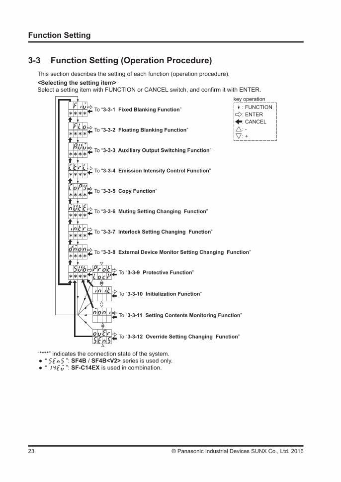
3-3 Function Setting (Operation Procedure)This section describes the setting of each function (operation procedure).<Selecting the setting item>Select a setting item with FUNCTION or CANCEL switch, and confirm it with ENTER.
* * * *
* * * *
* * * *
* * * *
* * * *
* * * *
* * * *
* * * *
* * * *
To “3-3-1 Fixed Blanking Function”
To “3-3-2 Floating Blanking Function”
To “3-3-3 Auxiliary Output Switching Function”
To “3-3-4 Emission Intensity Control Function”
To “3-3-5 Copy Function”
To “3-3-6 Muting Setting Changing Function”
To “3-3-7 Interlock Setting Changing Function”
To “3-3-8 External Device Monitor Setting Changing Function”
To “3-3-9 Protective Function”
To “3-3-10 Initialization Function”
To “3-3-11 Setting Contents Monitoring Function”
To “3-3-12 Override Setting Changing Function”
key operation: FUNCTION: ENTER: CANCEL: -: +
“****” indicates the connection state of the system. ● “ ”: SF4B / SF4B<V2> series is used only. ● “ ”: SF-C14EX is used in combination.

24© Panasonic Industrial Devices SUNX Co., Ltd. 2016
Function Setting
<Inputting a password>When the protective function is effective, “Lock” is shown on the lower section of the digital display. The functional settings of the SF4B / SF4B<V2> series cannot be changed unless the password is input. Note that “3-3-9 Protective Function” is “locked” even when the protective function is ineffective.
Remarks
1) “3-3-11 Setting Contents Monitoring Function” is not “locked.”2) Once the password is input, you do not need to input the password again till the power is
turned OFF. (Except “3-3-9 Protective Function”) However, if the power is turned ON again without changing the protective function to ineffective, the password have to be input again since the protective function is still effective.
The procedure for inputting a password is as follows. ● When using with SF4B / SF4B<V2> series only
key operation: ENTER: CANCEL: -: +
SF-C14EX
Input password
Complete inputting password
NG
Input password
CH1
CH2
CH3
Complete inputting password
NG
NG
NG
Complete inputting password for 1 unit
Complete inputting password for 2 units
● When using in combination with SF-C14EX

25 © Panasonic Industrial Devices SUNX Co., Ltd. 2016
<Selecting sensor>Each function can be set on each SF4B / SF4B<V2> series connected in series as well. Select a SF4B / SF4B<V2> series to set each function.
Remarks
Since “3-3-5 Copy Function” and “3-3-9 Protective Function” are set collectively, it is not necessary to select a sensor. Furthermore, when a SF4B / SF4B<V2> series unit is used, CH2 / CH3 cannot be selected. When two SF4B / SF4B<V2> series in series connection are used, CH3 cannot be selected.“3-3-3 Auxiliary Output Switching Function,” “3-3-7 Interlock Setting Changing Function” or “3-3-8 External Device Monitor Setting Changing Function” is set with CH1 only. CH2 and CH3 are not indicated.When using in combination with SF-C14EX, the setting of “Muting sensor output operating set-ting” of “3-3-5 Copy Function,” “Muting sensor output operating setting” of “3-3-6 Muting Set-ting Changing Function,” “3-3-7 Interlock Setting Changing Function,” “3-3-8 External De-vice Monitor Setting Changing Function” and “3-3-12 Override Setting Changing Function (Ver. 2.1 only)” cannot be changed.
Function Setting
*: When the units are not in series connection, it is not indicated.
CH3 (Sub sensor 2)
CH2 (Sub sensor 1)
CH1 (Main sensor)
ALL (All sensor) (*)
Em
itter
Rec
eive
r
Em
itter
Rec
eive
r
Em
itter
Rec
eive
r
26© Panasonic Industrial Devices SUNX Co., Ltd. 2016
Function Setting
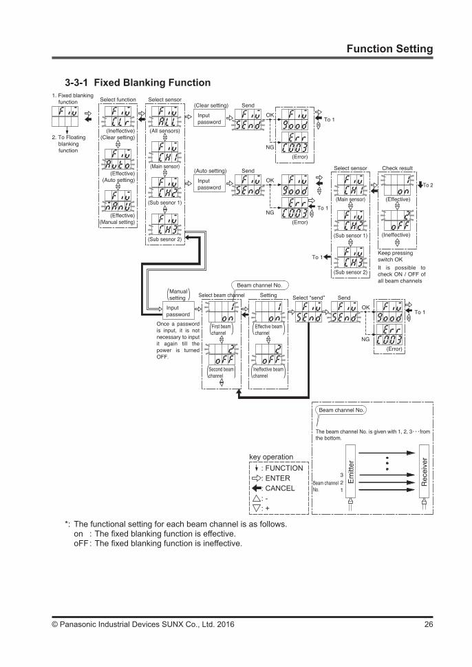
3-3-1 Fixed Blanking Function
(Sub sesnor 2)
1. Fixed blankingfunction
2. To Floating blanking function
Select function
(Ineffective)(Clear setting)
(Effective)(Auto setting)
(Effective)(Manual setting)
(All sensors)
(Main sensor)
(Sub sesnor 1)
Select sensor(Clear setting) Send
(Error)
To 1Input password
OK
NG
(Sub sensor 2)
(Main sensor)
(Sub sensor 1)
(Effective)
(Ineffective)
(Auto setting) Send
(Error)
To 1
To 1
To 2
Select sensor Check result
Keep pressing switch OKIt is possible to check ON / OFF of all beam channels
Inputpassword
OK
NG
Select “send”
(Error)
To 1
Send
Input password
Select beam channel SettingManual setting
OK
NG
Once a password is input, it is not necessary to input it again till the power is turned OFF.
Beam channel No.
First beam channel
Second beam channel
Effective beam channel
Ineffective beam channel
The beam channel No. is given with 1, 2, 3・・・from the bottom.
Beam channel No.
321
Beam channelNo.
Em
itter
Rec
eive
r
*: The functional setting for each beam channel is as follows.on : The fixed blanking function is effective.oFF : The fixed blanking function is ineffective.
key operation: FUNCTION: ENTER: CANCEL: -: +
27 © Panasonic Industrial Devices SUNX Co., Ltd. 2016
Function Setting
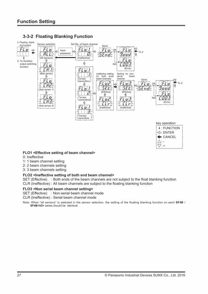
3-3-2 Floating Blanking Function
FLO1 <Effective setting of beam channel>0: Ineffective1: 1 beam channel setting2: 2 beam channels setting3: 3 beam channels settingFLO2 <Ineffective setting of both end beam channel>SET (Effective) : Both ends of the beam channels are not subject to the float blanking functionCLR (Ineffective) : All beam channels are subject to the floating blanking functionFLO3 <Non serial beam channel setting>SET (Effective) : Non-serial beam channel modeCLR (Ineffective) : Serial beam channel modeNote: When “all sensors” is selected in the sensor selection, the setting of the floating blanking function on each SF4B /
SF4B<V2> series should be identical.
(Sub sensor 2)
Sensor selection
(All sensors)
(Main sensor)
(Sub sensor 1)
Set No. of beam channel
(Ineffective)
Input password
Send
(Error)
To 2OK
NG
To 2Send
(Error)
OK
NG
(Ineffctive)
(Effctive)
(Ineffctive)
(Effctive)
Ineffective setting for both ends beam channels
Setting for non-serial beam channelOne beam
channel effecive
Two beam channel effecive
Three beam channel effecive
3. To Auxiliary output switching function
2. Floating blank- ing function
key operation: FUNCTION: ENTER: CANCEL: -: +

28© Panasonic Industrial Devices SUNX Co., Ltd. 2016
Function Setting
3-3-3 Auxiliary Output Switching Function
*: When two or more SF4B / SF4B<V2> series are connected, cancel the protective function of all SF4B / SF4B<V2> series.
<Setting of the auxiliary output>Mode 0: Negative logic of the control output (OSSD 1 / 2) (factory setting)Mode 1: Positive logic of the control output (OSSD 1 / 2)Mode 2: ON during emission, OFF when emission is not done.Mode 3: OFF during emission, ON when emission is not done.Mode 4: OFF when the received light level is unstable (Note 1)Mode 5: ON when the received light level is unstable (Note 1)Mode 6: ON during mutingMode 7: OFF during mutingMode 8: ON in the light receiving conditionMode 9: OFF in the light receiving conditionNotes: 1) This cannot be used when the fixed blanking function, the floating blanking function or the muting setting changing func-
tion is used. 2) When using with SF4B / SF4B<V2> series only, if the external device monitor function is not used, set the monitor set-
ting to ineffective in “3-3-8 External Device Monitor Setting Changing Function.”
(Mode 9)
4. To Emission intensity control function
Select output
(Mode 0)
(Mode 1)
(Mode 2)
Send
(Error)
To 3OK
NG
・・・
Input pass-word (*)
3. Auxiliary output switching function
key operation: FUNCTION: ENTER: CANCEL: -: +

29 © Panasonic Industrial Devices SUNX Co., Ltd. 2016
Function Setting
3-3-4 Emission Intensity Control Function
<Emission intensity control>CLR (Ineffective) : Operating range is 0.3 to 9m for SF4B-H□ / SF4B-H□<V2> (12 to 64 beam chan-
nels) and SF4B-A□ / SF4B-A□<V2> (6 to 32 beam channels), 0.3 to 7m for SF4B-F□ / SF4B-F□<V2> and SF4B-H□ / SF4B-H□<V2> (72 to 96 beam chan-nels) and SF4B-A□ / SF4B-A□<V2> (36 to 48 beam channels) (factory setting).
SET (Effective) : The operating range is reduced by approx. 50%.
(Sub sensor 2)
5. To Copyfunction
Select sensor
(All sensors)
(Main sensor)
(Sub sensor 1)
Emission intensity control
(Effective)
(Ineffective)
Send
(Error)
To 4OK
NG
Input pass-word
4. Emission intensity con- trol function
key operation: FUNCTION: ENTER: CANCEL: -: +

30© Panasonic Industrial Devices SUNX Co., Ltd. 2016
Function Setting
3-3-5 Copy Function
“****” indicates the connection state of the system.
● “ ”: SF4B / SF4B<V2> se-ries is used only.
● “ ”: SF-C14EX is used in combination.
*1: The setting of the relay monitor is as follows.
When set to ineffective: CLR When set to effective: Set time (100 to 600ms, in units of 10ms)*2: The override function can be set
in the range of 60 to 600 sec. (in units of 10 sec.)
Notes: 1) The indication is on the main sensor (CH1) only.
2) When using in combination with SF-C14EX, it is not indicated.
key operation: FUNCTION: ENTER: CANCEL: -: +
(Override)*2
(Note 1, 2) (Note 1)
Muting sensoroutput operationsetting
Muting lampdiagnosisfunction setting
5. Copy function Select function
(Upload)
(Download)
(Monitor)
Select sensor
Input password
Check function
6. To Muting setting changing function
(Error)
To 5
OK
NG
Receive
(Error)
To 5
OK
NG
ReceiveConfirm functionof system device
Select item
(Note 1)
(Note 1)(Note 2)
(Note 1)(Note 2)
(Note 1)(Note 2)
Detail display(Only for SET)
(Effective)
(Ineffective)
・・・
Keep pressing switch OK
Detail display(Only for SET)
(Effective)
(Ineffective)
・・・
Keep pressing switch OK
Detail display(Only for SET)
(Set beam channels)
Both ends beam channel ineffec-tive setting
Non-serial beam channel setting
(Emission intensity control)
(Input mode)
(Interlock)
(Relay monitor) *1
(Protection)
(Auxiliary output)
Fixed blanking effective / ineffective display
Floating blanking effective / ineffective display
* * * *
* * * *
31 © Panasonic Industrial Devices SUNX Co., Ltd. 2016
Function Setting
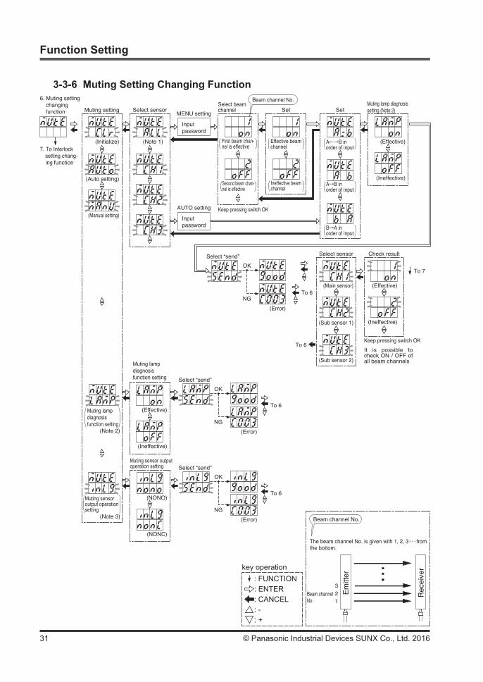
3-3-6 Muting Setting Changing Function
To 6
(Error)
OK
NG
Select “send”
(NONO)
(NONC)
(Note 3)
Muting sensor output operation setting
Muting sensor output operation setting
Muting setting
(Initialize) (Note 1)
Input password
Select sensorMENU setting
Input password
AUTO setting
6. Muting setting changing function
7. To Interlock setting chang- ing function
(Auto setting)
(Manual setting)
Set Set
Beam channel No.
Keep pressing switch OK
First beam chan-nel is effective
A←→B in order of input
A→B inorder of input
B→A inorder of input
Second beam chan-nel is effective
(Error)
OK
NG
Select “send”
To 7
(Sub sensor 2)
(Main sensor)
(Sub sensor 1)
(Effective)
(Ineffective)
To 6
To 6
Select sensor Check result
Keep pressing switch OK
It is possible to check ON / OFF of all beam channels
Effective beam channel
Ineffective beam channel
Select beam channel
(Effective)
(Ineffective)
Muting lamp diagnosis setting (Note 2)
Muting lampdiagnosis function setting
(Note 2)
To 6
(Error)
OK
NG
Select “send”
(Effective)
(Ineffective)
Muting lamp diagnosis function setting
The beam channel No. is given with 1, 2, 3・・・from the bottom.
Beam channel No.
321
Beam channelNo.
Em
itter
Rec
eive
rkey operation: FUNCTION: ENTER: CANCEL: -: +

32© Panasonic Industrial Devices SUNX Co., Ltd. 2016
Function Setting
*: The functional setting of each beam channel is as follows.on : The muting function is effective.oFF : The muting function is ineffective.
● CLR initializes the all settings. (factory setting)• All beam channels: Effective• Input condition: A = b• Muting lamp diagnosis function setting: Effective
● When changing only the setting of the muting input condition, set it by manual setting. The input condition can be set at SF4B / SF4B<V2> series respectively.
● When initializing only the beam channel that the muting is effective, set to the auto setting in the emission halt condition.
Notes: 1) “ALL” is displayed only when set by “Auto.” 2) When only using the SF4B / SF4B<V2> series, set the muting lamp diagnosis function on all SF4B / SF4B<V2> series. However, if the function has been set through CLr / Auto / ManU on each SF4B / SF4B<V2> series, set the function on
the SF4B / SF4B<V2> series. When using SF-C14EX, this function is set on the SF-C14EX. In this case, set the func-tion in the same way when “ALL” is selected.
3) It is not indicated when using with SF4B series. In addition, it is not indicated when using with SF-C14EX, either.

33 © Panasonic Industrial Devices SUNX Co., Ltd. 2016
Function Setting
3-3-7 Interlock Setting Changing Function
*: When two or more SF4B / SF4B<V2> series are connected, cancel the protective function of all SF4B / SF4B<V2> series.
<Setting of the interlock>Mode 0: Start / restart interlock function (factory setting)Mode 1: Start interlock functionMode 2: Restart interlock functionMode 3: IneffectiveNote: When using SF-C14EX, the display does not change even if ENTER key is pressed. (Mode 0, Start / Restart interlock function)
(Mode 0)
Input password
(Mode 1)
(Mode 2)
8. To External device monitor setting changing function
Setting selection
(Mode 3)
Send
(Error)
To 7 OK
NG
7. Interlock setting changing function
key operation: FUNCTION: ENTER: CANCEL: -: +

34© Panasonic Industrial Devices SUNX Co., Ltd. 2016
Function Setting
3-3-8 External Device Monitor Setting Changing Function
*: When two or more SF4B / SF4B<V2> series are connected, cancel the protective function of all SF4B / SF4B<V2> series.
<External device monitor>CLR (Ineffective) : The external device monitor function is ineffective.SET (Effective) : The external device monitor function is effective. (The factory setting is 300ms.)Note: When using SF-C14EX, the display does not change even if ENTER key is pressed. (The external device monitor: Effective)
(Ineffective)
(Effective)
9. To Sub display function / Protect function
8. External device monitor setting changing function Relay monitor setting Send
(Error)
To 8OK
NGTime setting
(100ms)
(600ms)
(110ms)
(120ms)
・・・
Input pass-word
key operation: FUNCTION: ENTER: CANCEL: -: +

35 © Panasonic Industrial Devices SUNX Co., Ltd. 2016
Function Setting
3-3-9 Protective Function ● When using with SF4B / SF4B<V2> series only
● When using in combination with SF-C14EX
Send
(Error)
To 9OK
NG
Send
(Error)
To 9OK
NG
(All sensors)
(Main sensor)
10. To Sub dis- play function / Initialization function
9. Sub display function / Pro- tect function Select sensor
(Sub sensor 1)
(Sub sensor 2)
Select function
(Eeffctive)
(Ineffctive)
(Change password)
Input password
Input new password (*)
Increase / decrease the No. with
Send
(Error)
To 9OK
NG
Send
(Error)
To 9OK
NG
Select sensor Select function
(Eeffctive)
(Ineffctive)
(Change password)
Input password
Input new password
10. To Sub dis- play function / Initialization function
9. Sub display function / Pro- tect function
Increase / decrease the No. with
*: When the units are connected in series, the indication is as follows. CH1: “ ” CH2: “ ” CH3: “ ”
key operation: FUNCTION: ENTER: CANCEL: -: +
key operation: FUNCTION: ENTER: CANCEL: -: +
36© Panasonic Industrial Devices SUNX Co., Ltd. 2016
Function Setting
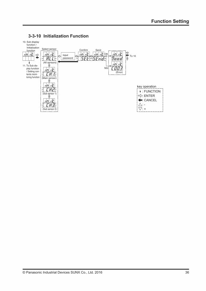
3-3-10 Initialization Function
(All sensors)
(Main sensor)
11. To Sub dis- play function / Setting con- tents moni- toring function
10. Sub display function / Initialization function
Select sensor
(Sub sensor 1)
(Sub sensor 2)
Input password
Send
(Error)
To 10OK
NG
Confirm
key operation: FUNCTION: ENTER: CANCEL: -: +

37 © Panasonic Industrial Devices SUNX Co., Ltd. 2016
Function Setting
3-3-11 Setting Contents Monitoring Function
(NONO)
Muting sensoroutput operationsetting
*: 60 to 600 (unit of 10)
(Note 1)(Note 2)
(Note 2)
Override setting changing function
(Main sensor)12. To Sub display function / Over- ride setting changing function
11. Sub display function / Set- ting contents monitoring function
Select sensor
(Sub sensor 1)
(Sub sensor 2)
(Current setting)
Fixed blankingfunction
(Record 1)
(Record 5)
・・・
(Effective)
(Ineffective)
Detail display(Only for SET)
Keep pressing switch OK(Current setting)
Floating blankingfunction
(Record 1)
(Record 5)
・・・
(Effective)
(Effective)
Detail display(Only for SET)
Keep pressing switch OK
(Effective)
(Effective)
(Note)
(Emission intensity control function)
(Positive logic of OSSD)(Auxiliary output switching function)
(Protect function)
Fixed blankingfunction
Floating blankingfunction
*:
(Mode 1)
(Effective)
(Model No.)(No. of beam channel)
CLR, 100 to 600 (unit of 10)
(Note 1)(Note 2)
(Note 1)(Note 2)
Muting setting changing function
Interlock setting changing function
External device monitorsetting changing function
(Current setting)
Muting on each beam channel
(Record 1)
(Record 5)
・・・
(Effective)
(Ineffective)
Keep pressing switch OK
Beam channel display of the record 0 (Only for SET)
(Effective)
Muting lampdiagnosis function setting
Notes: 1) The indication is on the main sensor (CH1) only. 2) When using SF-C14EX, this is not indicated.
key operation: FUNCTION: ENTER: CANCEL: -: +

38© Panasonic Industrial Devices SUNX Co., Ltd. 2016
Function Setting
3-3-12 Override Setting Changing Function (Ver. 2.1 only)
Send
(Error)
To 12OK
NG
Time setting
(60 sec.)
・・・
(70 sec.)
(80 sec.)
(600 sec.)
9. To Sub display function / Protect function
12. Override setting changing function
Input pass-word
*: When two or more SF4B / SF4B<V2> series are connected, cancel the protective function of all SF4B / SF4B<V2> series.
Notes: 1) The factory setting is 60 sec. 2) It is not indicated when using with SF4B series. In addition, it is not indicated when using with SF-C14EX, either.
key operation: FUNCTION: ENTER: CANCEL: -: +

39 © Panasonic Industrial Devices SUNX Co., Ltd. 2016
CHAPTER 4 TROUBLESHOOTING
Symptoms Cause RemedyControl output (OSSD 1 / 2) is not turned ON.
This device is connected to the SF4B / SF4B<V2> series. Disconnect this device.
Symptoms Cause RemedySafety output 1 / 2 is not turned ON. This device is connected to the SF-C14EX. Disconnect this device.
Error indication Cause RemedyThe fixed blanking function is set in all lights received / all lights blocked condi-tion, or the muting function is set in all lights received condition.
Do not set the fixed blanking function in all lights received / all lights blocked condition, or the muting function in all lights received condition.
The copy function is used for the units having different system configuration from each other (the number of sensors / the number of beam channels / model No. is not same).
Use the copy function for the units having identical system configuration.
In the copy function, download the data without uploading. Upload the data before downloading.
The password does not match. Input the correct password. In case you for-get the password, contact us. (Note)
Sensor communication error 1(Model No. is wrong)
Connect this device to SF4B / SF4B<V2> series.
Sensor communication error 2Wrong wiring between the emitter and receiver.
Connect the emitter and receiver correctly.
Sensor communication error 3Effect from noise or failure of internal circuit
Check the noise state around the SF4B / SF4B<V2> series.
Failure of EEPROM in this device.(Failure on device) Contact us.
Failure of EEPROM in this device.(Failure on EEPROM data) Contact us.
Note: The factory setting of the SF4B / SF4B<V2> series password is “0000.”
If this device does not work, press ENTER key or CANCEL key one minute after pressing ENTER key.If the device does not work correctly after checking the items above, please consult us.

40© Panasonic Industrial Devices SUNX Co., Ltd. 2016
CHAPTER 5 SPECIFICATIONS / DIMENSIONS
5-1 SpecificationsModel No.
Item SFB-HC (Ver.2.1)
Applicable model Light curtain SF4B/SF4B<V2> series, Application expansion unit SF-C14EXSupply voltage 24V DC±10% Ripple P-P 10% or less (common to sensor power supply)Current consumption 65mA or lessCommunication method RS-485 two-way communications (specific procedure)Digital display 4-digit red LED display × 2 (selected beam channels, setting contents etc. are displayed. )FUNCTION indicator Green LED × 9 (lights up when each functional setting is ON)
Functions
Fixed blanking function, Floating blanking function, Auxiliary output switching functionEmission intensity control function, Copy function (Note 1), Muting setting changing functionInterlock setting changing function (Note 2), External device monitor setting changing function (Note 2)Protective function, Initialization function, Setting contents monitoring function andOverride setting changing function (Note 2, 3)
Ambient temperature -10 to +55°C (No dew condensation or icing allowed), Storage: -25 to +70°CAmbient humidity 30 to 85% RH, Storage: 30 to 85% RHVoltage withstandability 1,000V AC for one minute between all supply terminals connected together and enclosureInsulation resistance 20MΩ or more, with 500V DC megger between all supply terminals connected together and enclosureCable 8-core shielded cable with a connector on one end 0.5m long (2 pcs.)Weight Approx. 200gAccessory SFB-CCJ02-HC (Conversion cable): 2 pcs.
Notes: 1) There may be a case that the copied data through the copy function is deleted due to external causes. After the copy function was used, check the copied data.
2) When using in combination with SF-C14EX, the setting cannot be changed. 3) When using with SF4B series, the setting cannot be changed.
5-2 Dimensions(Unit: mm)
25.423
3065
140
ø6 cable 0.5m long
41 © Panasonic Industrial Devices SUNX Co., Ltd. 2016
Revision historyFirst edition May 13, 2005Second edition July 14, 2005Third edition October 11, 2005Fourth edition April 28, 2006Fifth edition November 17, 2008Sixth edition July 1, 2011Seventh edition March 1, 2013

1. WARRANTIES:(1) Subject to the exclusions stated in 2 (EXCLUSIONS) herein below, Panasonic Industrial Devices SUNX
warrants the Products to be free of defects in material and workmanship for a period of one (1) year from the date of shipment under normal usage in environments commonly found in manufacturing industry.
(2) Any Products found to be defective must be shipped to Panasonic Industrial Devices SUNX with all ship-ping costs paid by Purchaser or offered to Panasonic Industrial Devices SUNX for inspection and examina-tion. Upon examination by Panasonic Industrial Devices SUNX, Panasonic Industrial Devices SUNX will, at its sole discretion, repair or replace at no charge, or refund the purchase price of, any Products found to be defective.
2. EXCLUSIONS:(1) This warranty does not apply to defects resulting from any cause:
(i) which was due to abuse, misuse, mishandling, improper installation, improper interfacing, or improper repair by Purchaser;
(ii) which was due to unauthorized modification by Purchaser, in part or in whole, whether in structure, per-formance or specification;
(iii) which was not discoverable by a person with the state-of-the-art scientific and technical knowledge at the time of manufacture;
(iv) which was due to an operation or use by Purchaser outside of the limits of operation or environment specified by Panasonic Industrial Devices SUNX;
(v) which was due to normal wear and tear; (vi) which was due to Force Majeure; and(vii) which was due to any use or application expressly discouraged by Panasonic Industrial Devices SUNX
in 4 (CAUTIONS FOR SAFE USE) hereunder.(2) This warranty extends only to the first purchaser for application, and is not transferable to any person or en-
tity which purchased from such purchaser for application.3. DISCLAIMERS(1) Panasonic Industrial Devices SUNX's sole obligation and liability under this warranty is limited to the repair or
replacement, or refund of the purchase price, of a defective Product, at Panasonic Industrial Devices SUNX's option.
(2) THE REPAIR, REPLACEMENT, OR REFUND IS THE EXCLUSIVE REMEDY OF THE PURCHASER, AND ALL OTHER WARRANTIES, EXPRESS OR IMPLIED, INCLUDING, WITHOUT LIMITATION, THE WAR-RANTIES OF MERCHANTABILITY, FITNESS FOR A PARTICULAR PURPOSE, AND NON-INFRINGE-MENT OF PROPRIETARY RIGHTS, ARE HEREBY EXPRESSLY DISCLAIMED. IN NO EVENT SHALL PANASONIC Industrial Devices SUNX AND ITS AFFILIATED ENTITIES BE LIABLE FOR DAMAGES IN EXCESS OF THE PURCHASE PRICE OF THE PRODUCTS, OR FOR ANY INDIRECT, INCIDENTAL, SPECIAL OR CONSEQUENTIAL DAMAGES OF ANY KIND, GENERAL TERMS AND CONDITIONS 4 OR ANY DAMAGES RESULTING FROM LOSS OF USE, BUSINESS INTERRUPTION, LOSS OF INFORMA-TION, LOSS OR INACCURACY OF DATA, LOSS OF PROFITS, LOSS OF SAVINGS, THE COST OF PROCUREMENT OF SUBSTITUTED GOODS, SERVICES OR TECHNOLOGIES, OR FOR ANY MATTER ARISING OUT OF OR IN CONNECTION WITH THE USE OR INABILITY TO USE THE PRODUCTS.
4. CAUTIONS FOR SAFE USE(1) The applications shown in the catalogue are only suggestions, and it is Purchaser's sole responsibility to
ascertain the fitness and suitability of the Products for any particular application, as well as to abide by Purchaser's applicable local laws and regulations, if any.
(2) Never use the Products NOT rated or designated as “SAFETY SENSOR” in any application involving risk to life or property. When such a use is made by Purchaser, such Purchaser shall indemnify and hold harmless Pana-sonic Industrial Devices SUNX from any liability or damage whatsoever arising out of or in relation to such use.
(3) In incorporating the Products to any equipment, facilities or systems, it is highly recommended to employ fail-safe designs, including but not limited to a redundant +++design, flame propagation prevention design, and malfunction prevention design so as not to cause any risk of bodily injury, fire accident, or social dam-age due to any failure of such equipment, facilities or systems.
(4) The Products are each intended for use only in environments commonly found in manufacturing industry, and, unless expressly allowed in the catalogue, specification or otherwise, shall not be used in, or incorpo-rated into, any equipment, facilities or systems, such as those:
(a) which are used for the protection of human life or body parts;(b) which are used outdoors or in environments subject to any likelihood of chemical contamination or elec-
tromagnetic influence;(c) which are likely to be used beyond the limits of operations or environments specified by Panasonic In-
dustrial Devices SUNX in the catalogue or otherwise;(d) which may cause risk to life or property, such as nuclear energy control equipment, transportation equip-
ment (whether on rail or land, or in air or at sea), and medical equipment;(e) which are operated continuously each day for 24 hours; and(f) which otherwise require a high level of safety performance similar to that required in those equipment,
facilities or systems as listed in (a) through (e) above.5. EXPORT CONTROL LAWS In some jurisdictions, the Products may be subject to local export laws and regulations. If any diversion or re-export is
to be made, Purchaser is advised to abide by such local export laws and regulations, if any, at its own responsibility.

http://panasonic.net/id/pidsx/globalOverseas Sales Division (Head Office) 2431-1 Ushiyama-cho, Kasugai-shi, Aichi, 486-0901, Japan Phone: +81-568-33-7861 FAX: +81-568-33-8591For sales network, please visit our website.
PRINTED IN JAPAN © Panasonic Industrial Devices SUNX Co., Ltd. 2016


