35
SGX3500 SGX5000 SGX7500

SGX3500 SGX5000 SGX7500

AIR INDEX
Descriptive Term Applicable to Emissions Durability Period
Moderate - 50 hours (engine from 0 to 80 cc)125 hours (engine greater than 80 cc)
Intermediate - 125 hours (engine from 0 to 80 cc)250 hours (engine greater than 80 cc)
Extended - 300 hours (engine from 0 to 80 cc)500 hours (engine greater than 80 cc)
1000 hours (225 cc and greater)
WARNING:The engine exhaust from this product contains chemicals known to the State of California tocause cancer, birth defects or other reproductiveharm.
To show compliance with California emission regulations, a hangtag has been provideddisplaying the Air Index level and durability period of this engine.
The Air Index level defines how clean an engine’s exhaust is over a period of time. A bar graph scaled from “0” (most clean) to “10” (least clean) is used to show an engine’s Air Index level. A lower Air Index level represents cleaner exhaust from an engine.
The period of time (in hours) that the Air Index level is measured is known as the durability period. Depending on the size of the engine, a selection of time periods can be used to measure the Air Index level (see below).
Notice : This hangtag must remain on this engine or piece of equipment, and only be removed by the ultimate purchaser before operation.
Notice : FEDERAL EMISSION COMPONENT DEFECT WARRANTY and CALIFORNIA EMISSION CONTROL WARRANTY are applicable to only those engines/ generators complied with EPA (Environmental Protection Agency) and CARB (California Air Resources Board) emission regulations in the U.S.A.
Notice : To the engines/generators exported to and used in the countries other than the U.S.A., warranty service shall be performed by the distributor in each country in accordance with the standard SUBARU engine/generator warranty policy as applicable.
(California Proposition 65)
(California only)
Notice : There is permanent conductor between the generator (Stator Winding) and the frame.
SGX3500-7500 OM ce_GU7719.indd 001 2014/08/23 11:11:03

SGX3500-7500 OM ce_GU7719.indd 002 2014/08/23 11:11:03
FR
AN
ÇA
ISE
ES
PA
ÑO
L
SUBARU Industrial Power Products905 Telser Road • Lake Zurich, IL 60047 • USA •Toll Free: 800-277-6246 • 847-540-7300
www.subarupower.com
PRODUCT REGISTRATION
Please take a moment to register your product to ensure easy warranty qualifi cation and product updates.
Please register online at: www.SubaruPower.com/register
You will need the following two pieces of information to complete your product registration.
FOREWORD
Thank you for choosing a SUBARU GENERATOR.
This manual covers operation and maintenance of the SUBARU GENERATORS. All information in this
publication is based on the latest production information available at the time of printing.
Keep this owner’s manual at hand, so you can refer to it when needed.
Due to constant efforts to improve our products, certain procedures and specifi cations are subject to
change without notice.
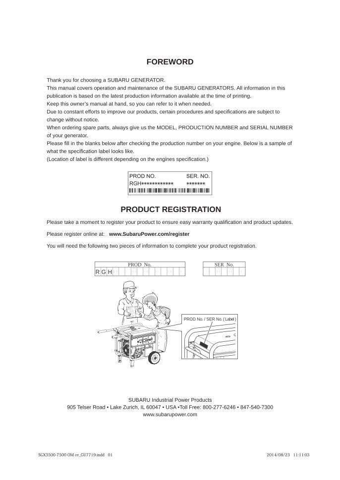
When ordering spare parts, always give us the MODEL, PRODUCTION NUMBER and SERIAL NUMBER
of your generator.
Please fi ll in the blanks below after checking the production number on your engine. Below is a sample of
what the specifi cation label looks like.
(Location of label is different depending on the engines specifi cation.)
PROD No. SER No.
PROD No. / SER No. ( Label )
R G H
SGX3500-7500 OM ce_GU7719.indd 01 2014/08/23 11:11:03
EN
GL
ISH
FR
AN
ÇA
ISE
ES
PA
ÑO
L
Limited Engine Warranty(Effective with engines purchased from SUBARU Industrial Power Products, Lake Zurich, IL, after April 1, 2008)
Robin America, Inc. doing business as SUBARU Industrial Power Products, a division of Fuji Heavy Industries, Ltd. (herein “SIP”), warrants that each new engine sold by it will be free, under normal use and service, from defects in material and workmanship for a period listed below from the date of sale to the original retail purchaser. SIP’s obligation under this Limited warranty shall be limited to the repair and replacement, at SIP’s option, of any part or parts which upon examination is/are found, in SIP’s judgment, to have been defective in material or work manship. It shall be a condition of SIP’s obligation under this Limited Warranty that SIP, directly or through one of its Distributors or Service Centers authorized to service the particular engine involved, receive prompt notice of any warranty claim and that the engine or the part or parts claimed to be defec tive be promptly delivered, transportation prepaid, to such distributor or service Center for inspection and repair. All repairs qualifying under this Limited Warranty must be performed by SIP or one of its autho rized Distributors or Service Centers.
WARRANTY PERIODS:
SUBARU Four-Cycle, EX Series Gasoline Engines Limited 5 year Warranty
To Qualify for this Warranty:
SUBARU Engines must be purchased from a SUBARU Industrial Power Products dealer or distributor authorized to sell that product in North America.
The repair or replacement of any part or parts under this Limited Warranty shall not extend the term of the engine warranty beyond the original term as set forth above.
LIMITATIONS AND EXCLUSIONS: This Limited Warranty shall not apply to:
,oslA .tfahsknarc nekorb ro tneb a ot detaler noitarbiv yb desuac egamad tnatluser ro tfahsknarc nekorb ro tneB .1 damage caused by loose engine mounting bolts or improper or imbalanced accessories or blades mounted to the crankshaft.
,knat leuf eht ni leuf detan imatnoc ro dlo yb desuac egamad gnidulcni egarots degnolorp fo esuaceb deriuqer sriapeR .2 fuel lines or carburetor, sticky valves or corrosion and rust of engine parts.
,leehwy fl gnissim ro degamad ro deggolc ro dedaolrevo yb desuac netfo tsoM( .gnitaehrevo ot eud deriuqer riapeR .3 fan, inlet air passages, cooling fi ns or air shrouds.)
,sgnir notsip ,notsip nrow ni gnitluser netfo tsom( ecnanetniam renaelc ria reporpmi yb desuac raew detaler tirg ro triD .4 .)stnen opmoc lanretni rehto ro roterubrac ,sediug evlav ,sevlav ,srednilyc
.lio fo edarg reporpmi ro ytrid ,level lio wol yb desuac strap derocs ro nekorB .5
tnemecalper lamron ,tnem tsujda evlav ,ot detimil ton tub ,gnidulcni ecivres ecnanetniam lamron dna spu-enut enignE .6 of service items, fuel and lubricating oil, etc.
.gnideeps-revo ro noitacilppasim ,tnedicca ,esusim ,ecnegilgen ot tcejbus neeb sah hcihw enigne ynA .7
ylesrevda tnemgduj elos s’PIS ni hcihw rennam a ni enoyna yb deretla ro ,deriaper ,dellatsni neeb sah taht enigne ynA .8 affects its performance or reliability.
PIS yb devorppa ro derutcafunam ton stnenopmoc ro strap htiw deriaper ro htiw dett fi neeb sah hcihw enigne ynA .9 .ytiliba iler ro ecnamrofrep sti stceffa ylesrevda tnemgduj elos s’PIS ni hcihw
.enigne na ro tnenopmoc a fo efil eht detsuahxe sah esu lamron nehw secnatsnI .01
The customer is responsible for all transportation charges in connection with any warranty work.
SIP reserves the right to modify, alter or improve any engines or parts without incurring any oblig ation to modify or replace, any engine or parts previously sold without such modifi cation, alternation or improvement.
No person is authorized to give any other warranty or to assume any additional obligation on SIP’s behalf unless made in written and signed by an offi cer of SIP.
THIS WARRANTY, AND SIP’s OBLIGATION HERE UNDER, ARE IN LIEU OF ANY OTHER WARRANTIES OR OBLIGATIONS OF ANY KIND, EXPRESSED OR IMPLIED, INCLUDING ANY WARRANTIES OF MERCHANTABILITY OR FITNESS FOR A PARTICULAR PURPOSE. THERE ARE NO WARRANTIES WHICH EXTEND BEYOND THE DESCRIPTION ON THE FACE HERE-OF. SIP SHALL IN NO EVENT BE LIABLE FOR ANY CONSEQUENTIAL OR INCIDENTAL DAMAGES.
SGX3500-7500 OM ce_GU7719.indd 02 2014/08/23 11:11:04

EN
GL
ISH
FR
AN
ÇA
ISE
ES
PA
ÑO
L
Limited Generator Warranty(Effective with generators purchased from SUBARU Industrial Power Products, Inc., Lake Zurich, IL, after April 1, 2008)
Robin America, Inc. doing business as SUBARU Industrial Power Products, a division of Fuji Heavy Industries, Ltd. (herein “SIP”), warrants that each new generator sold by it will be free, under normal use and service, from defects in material and workmanship for a period listed below from the date of sale to the original retail purchaser. SIP’s obligation under this Limited warranty shall be limited to the repair and replacement, at SIP’s option, of any part or parts which upon examination is/are found, in SIP’s judgment, to have been defective in material or work manship. It shall be a condition of SIP’s obligation under this Limited Warranty that SIP, directly or through one of its Distributors or Service Centers authorized to service the particular engine involved, receive prompt notice of any warranty claim and that the engine or the part or parts claimed to be defec tive be promptly delivered, transportation prepaid, to such distributor or service Center for inspection and repair. All repairs qualifying under this Limited Warranty must be performed by SIP or one of its autho rized Distributors or Service Centers.
WARRANTY PERIODS:
SUBARU Four-Cycle, Air-Cooled, Gasoline Generator Limited 3 year Warranty
To Qualify for this Warranty:
SUBARU Generators must be purchased from a SUBARU Industrial Power Products dealer or distributor authorized to sell that product in North America.
The repair or replacement of any part or parts under this Limited Warranty shall not extend the term of the engine warranty beyond the original term as set forth above.
LIMITATIONS AND EXCLUSIONS: This Limited Warranty shall not apply to:
,knat leuf eht ni leuf detanimatnoc ro dlo yb desuac egamad gnidulcni egarots degnolorp fo esuaceb deriuqer sriapeR .1 fuel lines or carburetor, sticky valves or corrosion and rust of engine parts.
,leehwy fl gnissim ro degamad ro deggolc ro dedaolrevo yb desuac netfo tsoM( .gnitaehrevo ot eud deriuqer riapeR .2 fan, inlet air passages, cooling fi ns or air shrouds.)
,sgnir notsip ,notsip nrow ni gnitluser netfo tsom( ecnanetniam renaelc ria reporpmi yb desuac raew detaler tirg ro triD .3 .)stnen opmoc lanretni rehto ro roterubrac ,sediug evlav ,sevlav ,srednilyc
.lio fo edarg reporpmi ro ytrid ,level lio wol yb desuac strap derocs ro nekorB .4
tnemecalper lamron ,tnem tsujda evlav ,ot detimil ton tub ,gnidulcni ecivres ecnanetniam lamron dna spu-enut enignE .5 of service items, fuel and lubricating oil, etc.
elos s’PIS ni hcihw rennam a ni enoyna yb deretla ro ,deriaper ,dellatsni neeb sah taht rotareneg/enigne ynA .6 judgement adversely affects its performance or reliability.
devorppa ro derutcafunam ton stnenopmoc ro strap htiw deriaper ro htiw dett fi neeb sah hcihw rotareneg/enigne ynA .7 by SIP which in SIP’s sole judgment adversely affects its performance or reli ability.
,noitanimatnoc leuf ,raew lamron ,noisilloc ro/dna tnedicca yb degamad ro detceffa strap ot dnetxe ton seod ytnarraW .8 use in an application for which the product was not designed or any other misuse, neglect, incorporated or use of unsuitable electrical attachments or parts.
9. Instances where normal use has exhausted the life of a component.
ni/no detarepo eb ot tnempiuqe gnirewop rof deyolpme si rotareneg eht s’PIS fo lavorppa roirp yna tuohtiw ,esac nI .01 water and is located where it gets exposed to water.
The customer is responsible for all transportation charges in connection with any warranty work.
SIP reserves the right to modify, alter or improve any engines or parts without incurring any oblig ation to modify or replace, any engine/generator or parts previously sold without such modifi cation, alternation or improvement.
No person is authorized to give any other warranty or to assume any additional obligation on SIP’s behalf unless made in written and signed by an offi cer of SIP.
For optimum performance and safety, please read the owner’s manual before operating your SUBARU generator. Connection to house power requires a transfer device to avoid possible injury to power company personnel. Please consult a qualifi ed electrician.
THIS WARRANTY, AND SIP’s OBLIGATION HERE UNDER, ARE IN LIEU OF ANY OTHER WARRANTIES OR OBLIGATIONS OF ANY KIND, EXPRESSED OR IMPLIED, INCLUDING ANY WARRANTIES OF MERCHANTABILITY OR FITNESS FOR A PARTICULAR PURPOSE. THERE ARE NO WARRANTIES WHICH EXTEND BEYOND THE DESCRIPTION ON THE FACE HERE-OF. SIP SHALL IN NO EVENT BE LIABLE FOR ANY CONSEQUENTIAL OR INCIDENTAL DAMAGES.
SGX3500-7500 OM ce_GU7719.indd 03 2014/08/23 11:11:04
EN
GL
ISH
FR
AN
ÇA
ISE
ES
PA
ÑO
L
WORLD WIDE SUPPORT
SUBARU Engines are supported through a network of dozens of wholesale distributors and thousands of service dealers worldwide. Please use the following contacts to fi nd support nearest you.
Global Distributor Locator: www.subaru-robin.jp/index_e.html
North America:
SUBARU Industrial Power Products, Inc.905 Telser RoadLake Zurich, IL 60047 U.S.A.Tel.: 847-540-7300 • Fax: 847-438-5012Email: [email protected]: www.subarupower.comService Dealer Locator: www.subarupower.com
Asia:
Fuji Heavy Industries LTD. (Parent Company of SUBARU)4-410, Asahi, Kitamoto-shiSaitama 364-8511, JapanTel.: 81-48-593-7941 • 81-48-593-7965Web: www.subarupower-global.com/
Europe:
Robin Europe GmbHWillicher Damm 135-137D-41066 MönchengladbachTel.: +49 - (0)2161 - 63620 - 0 • Fax: +49 - (0)2161 - 63620-50E-Mail: [email protected]: www.robin-europe.de/html/eindex.htm
Australia:
Crommelins Machinery139 Welshpool RdWelshpool 6106Tel.: (08) 9350 5588 • Fax: (08) 9451 6381E-mail: [email protected]: www.crommelins.com.au
SGX3500-7500 OM ce_GU7719.indd 04 2014/08/23 11:11:04

EN
GL
ISH
FR
AN
ÇA
ISE
ES
PA
ÑO
L
CONTENTS
SYMBOLS
Fire, open fl ame and smoking prohibited.
On
Engine oil
Add oil
Plus ; positive polarity
Off Battery
Engine start (Electric Start)
Read Owner’s Manual
Exhaust gas is poisonous. Do not operate in an unventilated room or enclosed area.
Stay clear of the hot surface.
Stop the engine before refueling.
SAFETY PRECAUTIONS ......................................................................................... 1SPECIFICATIONS .................................................................................................... 4COMPONENTS ........................................................................................................ 5ASSEMBLY PROCEDURES .................................................................................... 6PRE-OPERATION CHECKS .................................................................................. 10OPERATING PROCEDURES ................................................................................ 13MAINTENANCE SCHEDULE ................................................................................. 20PREPARATION FOR STORAGE ........................................................................... 23TROUBLESHOOTING ........................................................................................... 24WIRING DIAGRAM ................................................................................................ 25
USA and CANADA only
Read INSTRUCTIONSFOR USE before use.
The engine emits toxic gascan kill you in minutes.Do not run in an enclosed area.
Hot surface can burn you. Stay away if engine has been running.
Gasoline is extremely flammable and its vapors can explode.• Stop the engine before refueling.• Check for leakage from hoses and fittings.• Shut off fuel valve when the engine is not in use.
SGX3500-7500 OM ce_GU7719.indd 05 2014/08/23 11:11:04

1
EN
GL
ISH
FR
AN
ÇA
ISE
ES
PA
ÑO
L
SAFETY PRECAUTIONS
Pay special attention to statements preceded by the following words:
DANGER
Indicates a possibility of death or serious injury if instructions are not followed.
WARNING
Indicates a strong possibility of severe personal injury, loss of life and equipment damage if instructions are not followed.
[ CAUTION ]Indicates a possibility of personal injury or equipment damage if instructions are not followed.
NOTE:Gives helpful information.
If a problem should arise, or if you have any questions about the generator, consult an authorized dealer or service shop.
• The generator is designed to give safe and dependable service if operated according to instructions.
• Do not operate the generator before you have read and understood the instructions. Failure to do so could result in death, personal injury or equipment damage.
WARNING
SGX3500-7500 OM ce_GU7719.indd 1 2014/08/23 11:11:04
2
EN
GL
ISH
FR
AN
ÇA
ISE
ES
PA
ÑO
L
SAFETY PRECAUTIONS
Please make sure you review each precaution carefully.
DANGER
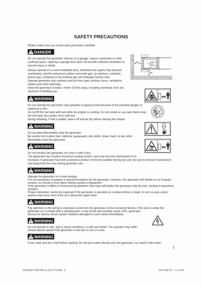
Do not operate the generator indoors, in a garage, carport, basement or other confi ned space. Opening a garage door does not provide suffi cient ventilation to prevent injury or death.
Always operate it in a well-ventilated area, otherwise the engine may become overheated, and the poisonous carbon monoxide gas, an odorless, colorless, poison gas, contained in the exhaust gas will endanger human lives.Operate generator only outdoors and far from open window, doors, ventilation intakes and other openings.Keep the generator at least 1 meter (3 feet) away, including overhead, from any structure of building use.
WARNING
Do not operate the generator near gasoline or gaseous fuel because of the potential danger of explosion or fi re.Do not fi ll the fuel tank with fuel while the engine is running. Do not smoke or use open fl ame near the fuel tank. Be careful not to spill fuel during refueling. If fuel is spilled, wipe it off and let dry before starting the engine.
WARNING
Do not place fl ammables near the generator.Be careful not to place fuel, matches, gunpowder, oily cloths, straw, trash, or any other fl ammables near the generator.
WARNING
Do not enclose the generator nor cover it with a box.The generator has a built-in forced air cooling system, and may become overheated if it is enclosed. If generator has been covered to protect it from the weather during non use, be sure to remove it and keep it well away from the area during generator use.
WARNINGOperate the generator on a level surface.It is not necessary to prepare a special foundation for the generator. However, the generator will vibrate on an irregular surface, so choose a level place without surface irregularities.If the generator is tilted or moved during operation, fuel may spill and/or the generator may tip over, causing a hazardous situation.Proper lubrication cannot be expected if the generator is operated on a steep incline or slope. In such a case, piston seizure may occur even if the oil is above the upper level.
WARNINGPay attention to the wiring or extension cords from the generator to the connected device. If the wire is under the generator or in contact with a vibrating part, it may break and possibly cause a fi re, generator burnout or electric shock hazard. Replace damaged or worn cords immediately.
WARNINGDo not operate in rain, wet or damp conditions, or with wet hands. The operator may suffer severe electric shock if the generator is wet due to rain or snow.
WARNINGIf wet, wipe and dry it well before starting, Do not pour water directly over the generator, nor wash it with water.
1m
1m
SGX3500-7500 OM ce_GU7719.indd 2 2014/08/23 11:11:04

3
EN
GL
ISH
FR
AN
ÇA
ISE
ES
PA
ÑO
L
WARNINGBe extremely careful that all necessary electrical grounding procedures are followed during each and every use. Failure to do so can be fatal.
WARNINGDo not connect the generator to a commercial power line. Connection to a commercial power line may short circuit the generator and ruin it or cause electric shock hazard. Use the transfer switch for connecting to domestic circuit.
WARNINGNo smoking while handling the battery. The battery emits fl ammable hydrogen gas, which can explode if exposed to electric arcing or open fl ame. Keep the area well-ventilated and keep open fl anges/sparks away when handling the battery.
WARNINGEngine becomes extremely hot during and for some time after operation. Keep combustible materials well away from generator area. Be very careful not to touch any parts of the hot engine especially the muffl er area or serious burns may result.
WARNINGKeep children and all bystander at a safe distance from work areas.
WARNINGIt is absolutely essential that you know the safe and proper use of the power tool or appliance that you intend to use. All operators must read, understand and follow the tool/appliance owners manual. Tool and appliance applications and limitations must be understood. Follow all directions given on labels and warnings. Keep all instruction manuals and literature in a safe place for future reference.
WARNINGUse only “LISTED” extension cords. When a tool or appliance is used outdoors, use only extension cords marked “For Outdoor Use”. Extension cords, when not in use should be stored in a dry and well ventilated area.
WARNINGAlways switch off generator’s AC circuit breaker and disconnect tools or appliance when not in use, before servicing, adjusting, or installing accessories and attachments.
WARNINGMake sure the engine is stopped before starting any maintenance, servicing or repair. Make sure maintenance and repair of the generator set are performed by properly trained personnel only.
WARNINGDo not allow drunk driving.
WARNINGDo not use the generator as electric power for medical appliance.
CAUTION : PRECAUTIONS ON THE HANDLING OF THE WARNING LABELWarning labels are affi xed to our engines with regard to particularly serious dangers.When using the engines, please use them safely after carefully reading the instruction manual and understanding thedangers.
Warning Label Exclusively for the United States and Canada
For use in the United States or Canada, please affix the label suited to the region from among the enclosed warning labels.
AVERTISSEMENTLire les INSTRUCTIONS POUR L'USAGE avant d’utiliser le moteur.
L'essence est extrêmement inflammable et ses vapeurs peuvent exploser.• Arrêter le moteur avant de faire le plein en combustible.• Vérifier toute présence de fuite à partir des tuyaux et garnitures.• Bloquer la soupape de carburant quand le moteur n’est pas utilisé.
Le moteur émet un gaz toxique qui peut tuer l’opérateur en quelques minutes. Ne pas utiliser le moteur dans un emplacement fermé.
La surface chaude peut vous brûler.S’éloigner du moteur s’il est en marche.
ADVERTENCIALeer las INSTRUCCIONES PARA EL USO antes de utilizar el motor.
La gasolina es extremadamente inflamable y sus vapores pueden estallar.• Detener el motor antes de hacer el lleno en combustible • Comprobar si hay presencia de fuga a partir los tubos y guarniciones • Bloquear la válvula de combustible cuando no se utiliza el motor.
El motor emite un gas tóxico que puede matar el operador en algunos minutos. No utilizar el motor en un sitio cerrado.
La superficie caliente puede quemarles.Alejarse del motor si es en marcha.
SGX3500-7500 OM ce_GU7719.indd 3 2014/08/23 11:11:04

4
EN
GL
ISH
FR
AN
ÇA
ISE
ES
PA
ÑO
L
SPECIFICATIONS
Model SGX3500 SGX5000 SGX7500Voltage Regulation Automatic Voltage Regulator (AVR)
Certification CSA / EPA Phase 3 / California Tier 3
Frequency/Phase 60Hz / Single Phase
Voltage 120/240
Max Output (watts) 3500 4900 7300
Max Amps (Amps@120V/240V) 29.1/14.5 40.8/20.4 60.8/30.4
Rated Output (watts) 3200 4500 6700
Rated Amps (Amps@120V/240V) 26.6/13.3 37.5/18.8 55.8/27.9
Current Protection Dual pole magnetic circuit breaker & GFCI
Ground systemAC system
Neutral bonded to frame
Engine (model and HP) EX21, 7HP EX30, 9.5HP EX40, 14HP
Type SUBARU Commercial Overhead Cam gasoline engine
Low Oil System Low Oil Shutdown Protection
Fuel Tank Capacity* Gal.(L) 3 (11.3) 6 (22.7)
Run time at 1/2 load (Hours) 7.8 10.8 7.7
Run time at rated load (Hours) 5.8 7.9 5.2
Starting System Recoil starter Electric starter / Recoil
Battery N/A Sealed 12 V 18 AHr.
Dimensions LxWxH (inch/ mm)**
28” x 25” x 26”(702 x 626 x 658)"
30” x 29” x 29”(763 x 726 x 737)
Dimensions less wheel kitLxWxH (inch/ mm)
26” x 17” x 21”(661 x 432 x 534)"
28” x 21” x 24”(712 x 534 x 610)
Dry Weight (lbs/ kg) includes wheel kit
137 (62) 177 (80) 229 (104)
GFCI 120V, 20A duplex 2 2 2
120V, 30A Twist lock N/A 1 1
120/240V, 30A Twist lock 1 1 1
Hour meter Yes Yes Yes
Wheel Kit Yes Yes Yes
Specifi cations are subject to change without notice.
:swollof sa si enilcni eerged 51 a ta derusaem yticapac knat leuF *
SGX3500 - 3 gal (11.3 L), SGX5000/SGX7500 - 6 gal (22.7 L)
** Include wheel kit and extended handles
SGX3500-7500 OM ce_GU7719.indd 4 2014/08/25 11:12:34

5
EN
GL
ISH
FR
AN
ÇA
ISE
ES
PA
ÑO
L
COMPONENTS
Spark Plug Cap
Choke Lever
Muffler
SparkArrestor
Tank Cap Fuel Gauge
Control Panel
Oil Drain
Recoil StarterHandle
Fuel Tank
HandleFrame
Air Filter
Wheel
Handle Lock Pin
Foot
Battery(Electric starter model)
Oil Gauge(Oil Filler Cap)
Key Switch(Electric starter model)
Canister
SGX3500-7500 OM ce_GU7719.indd 5 2014/08/23 11:11:05
6
EN
GL
ISH
FR
AN
ÇA
ISE
ES
PA
ÑO
L
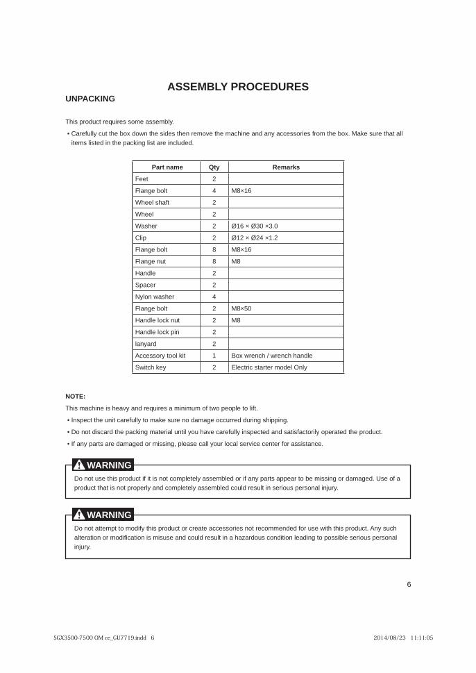
ASSEMBLY PROCEDURESUNPACKING
This product requires some assembly.
lla taht erus ekaM .xob eht morf seirossecca yna dna enihcam eht evomer neht sedis eht nwod xob eht tuc ylluferaC • items listed in the packing list are included.
Part name Qty Remarks
Feet 2
Flange bolt 4 M8×16
Wheel shaft 2
Wheel 2
Washer 2 Ø16 × Ø30 ×3.0
Clip 2 Ø12 × Ø24 ×1.2
Flange bolt 8 M8×16
Flange nut 8 M8
Handle 2
Spacer 2
Nylon washer 4
Flange bolt 2 M8×50
Handle lock nut 2 M8
Handle lock pin 2
lanyard 2
Accessory tool kit 1 Box wrench / wrench handle
Switch key 2 Electric starter model Only
NOTE:
This machine is heavy and requires a minimum of two people to lift.
.gnippihs gnirud derrucco egamad on erus ekam ot ylluferac tinu eht tcepsnI •
.tcudorp eht detarepo ylirotcafsitas dna detcepsni ylluferac evah uoy litnu lairetam gnikcap eht dracsid ton oD •
.ecnatsissa rof retnec ecivres lacol ruoy llac esaelp ,gnissim ro degamad era strap yna fI •
Do not use this product if it is not completely assembled or if any parts appear to be missing or damaged. Use of a product that is not properly and completely assembled could result in serious personal injury.
WARNING
Do not attempt to modify this product or create accessories not recommended for use with this product. Any such alteration or modifi cation is misuse and could result in a hazardous condition leading to possible serious personal injury.
WARNING
SGX3500-7500 OM ce_GU7719.indd 6 2014/08/23 11:11:05
7
EN
GL
ISH
FR
AN
ÇA
ISE
ES
PA
ÑO
L
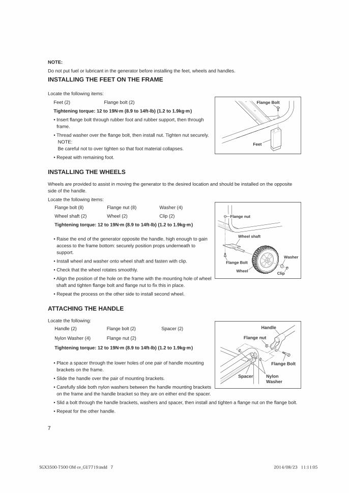
NOTE:
Do not put fuel or lubricant in the generator before installing the feet, wheels and handles.
INSTALLING THE FEET ON THE FRAME
Locate the following items:
Feet (2) Flange bolt (2)
Tightening torque: 12 to 19N·m (8.9 to 14ft-lb) (1.2 to 1.9kg·m)
hguorht neht ,troppus rebbur dna toof rebbur hguorht tlob egna fl tresnI • frame.
• Thread washer over the fl ange bolt, then install nut. Tighten nut securely. NOTE: Be careful not to over tighten so that foot material collapses.
• Repeat with remaining foot.
INSTALLING THE WHEELS
Wheels are provided to assist in moving the generator to the desired location and should be installed on the opposite side of the handle.
Locate the following items:
Flange bolt (8) Flange nut (8) Washer (4)
Wheel shaft (2) Wheel (2) Clip (2)
Tightening torque: 12 to 19N·m (8.9 to 14ft-lb) (1.2 to 1.9kg·m)
niag ot hguone hgih ,eldnah eht etisoppo rotareneg eht fo dne eht esiaR • access to the frame bottom: securely position props underneath to support.
• Install wheel and washer onto wheel shaft and fasten with clip.
• Check that the wheel rotates smoothly.
• Align the position of the hole on the frame with the mounting hole of wheel shaft and tighten fl ange bolt and fl ange nut to fi x this in place.
• Repeat the process on the other side to install second wheel.
ATTACHING THE HANDLE
Locate the following:
Handle (2) Flange bolt (2) Spacer (2)
Nylon Washer (4) Flange nut (2)
Tightening torque: 12 to 19N·m (8.9 to 14ft-lb) (1.2 to 1.9kg·m)
gnitnuom eldnah fo riap eno fo seloh rewol eht hguorht recaps a ecalP • brackets on the frame.
• Slide the handle over the pair of mounting brackets.
stekcarb gnitnuom eldnah eht neewteb srehsaw nolyn htob edils ylluferaC • on the frame and the handle bracket so they are on either end the spacer.
.tlob egna fl eht no tun egna fl a nethgit dna llatsni neht ,recaps dna srehsaw ,stekcarb eldnah eht hguorht tlob a dilS •
• Repeat for the other handle.
Feet
Flange Bolt
Flange Bolt
Wheel
Wheel shaft
Washer
Clip
Flange nut
Flange nut
Flange Bolt
Spacer
Handle
NylonWasher
SGX3500-7500 OM ce_GU7719.indd 7 2014/08/23 11:11:05

8
EN
GL
ISH
FR
AN
ÇA
ISE
ES
PA
ÑO
L
LOCKING THE HANDLE
Locate the following items:
Handle lock pin (2) Lanyard (2)
• Attach the lanyard to the handle lock pin and the handle.
eloh eht hguorht nip eht tresni neht ,eldnah eht dnetxE • in the handle and the generator frame to secure handle in place.
rehto eht kcol ot edis rehto eht no ssecorp eht taepeR • handle.
RELEASING THE HANDLES
Remove the handle lock pins and lower the handles to the down position.
lanyard
Handle lock pin
Do not attempt to lift the unit by the handle assembly. If it is necessary to lift the generator, always grasp by the frame. Use proper lifting means to avoid back injury.
[CAUTION]
SGX3500-7500 OM ce_GU7719.indd 8 2014/08/23 11:11:05

9
EN
GL
ISH
FR
AN
ÇA
ISE
ES
PA
ÑO
L
CONTROL PANEL
(SGX3500)
(SGX7500)
(SGX5000)
Hourmeter
Engineswitch
AC circuitbreaker
AC receptacle20A (MAX 20A)
AC receptacle30A (MAX 28A)
Earth (ground)terminal
AC receptacle20A (MAX 20A)
AC receptacle30A (MAX 28A)
Earth (ground)terminal
Hourmeter
Engineswitch
AC circuitbreaker
AC receptacle20A (MAX 20A)
AC receptacle30A (MAX 28A)
Earth (ground)terminal
Hourmeter
Engineswitch
AC circuitbreaker
AC circuitbreaker
SGX3500-7500 OM ce_GU7719.indd 9 2014/08/23 11:11:05
10
EN
GL
ISH
FR
AN
ÇA
ISE
ES
PA
ÑO
L
PRE-OPERATION CHECKS
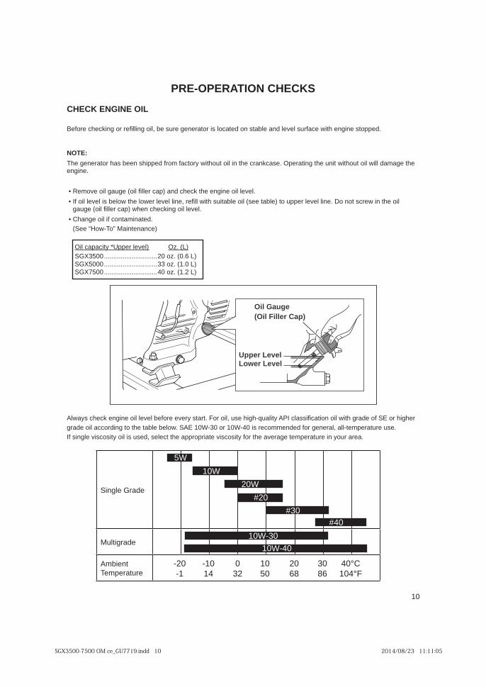
CHECK ENGINE OIL
Before checking or refi lling oil, be sure generator is located on stable and level surface with engine stopped.
NOTE:
The generator has been shipped from factory without oil in the crankcase. Operating the unit without oil will damage the engine.
• Remove oil gauge (oil fi ller cap) and check the engine oil level.
lio eht ni wercs ton oD .enil level reppu ot )elbat ees( lio elbatius htiw ll fier ,enil level rewol eht woleb si level lio fI • gauge (oil fi ller cap) when checking oil level.
.detanimatnoc fi lio egnahC • (See “How-To” Maintenance)
Single Grade
Multigrade
Ambient Temperature
-20 -10 0 10 20 30 40°C -1 14 32 50 68 86 104°F
5W
10W
20W
#20
#30#40
10W-30
10W-40
Oil capacity *Upper level) Oz. (L)SGX3500 .............................20 oz. (0.6 L)SGX5000 .............................33 oz. (1.0 L)SGX7500 .............................40 oz. (1.2 L)
Upper LevelLower Level
Oil Gauge(Oil Filler Cap)
Always check engine oil level before every start. For oil, use high-quality API classifi cation oil with grade of SE or higher grade oil according to the table below. SAE 10W-30 or 10W-40 is recommended for general, all-temperature use. If single viscosity oil is used, select the appropriate viscosity for the average temperature in your area.
SGX3500-7500 OM ce_GU7719.indd 10 2014/08/23 11:11:05
11
EN
GL
ISH
FR
AN
ÇA
ISE
ES
PA
ÑO
L
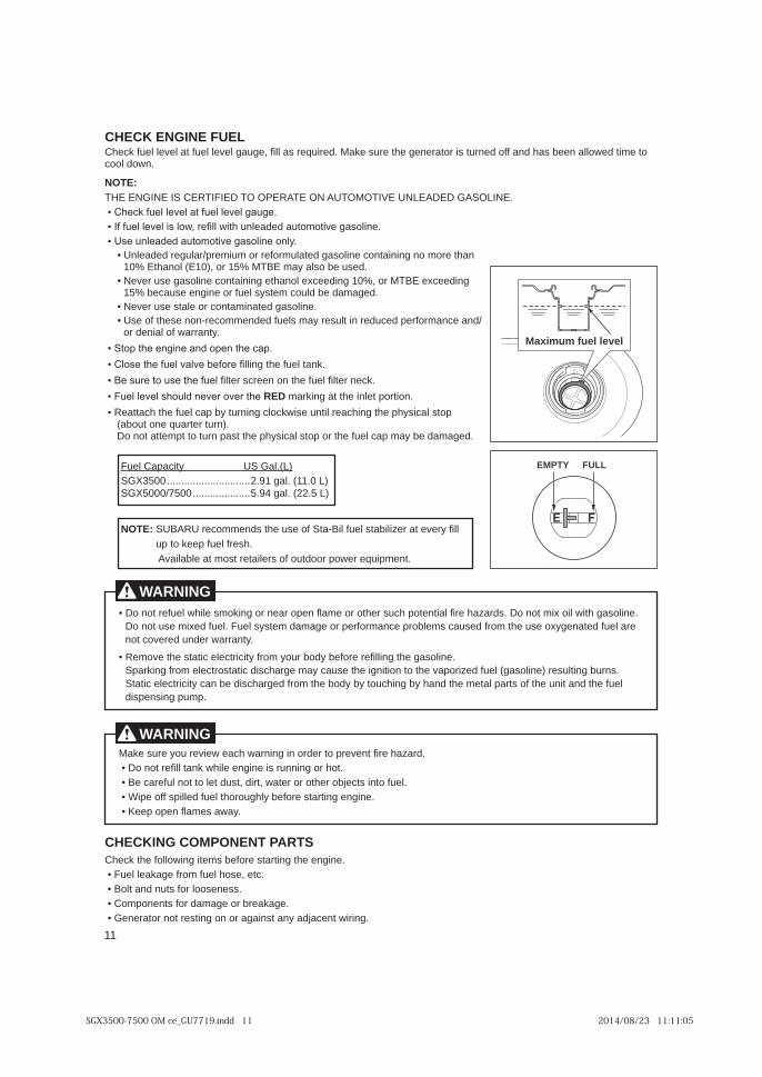
CHECK ENGINE FUELCheck fuel level at fuel level gauge, fi ll as required. Make sure the generator is turned off and has been allowed time to cool down.
NOTE:THE ENGINE IS CERTIFIED TO OPERATE ON AUTOMOTIVE UNLEADED GASOLINE. ▪ Check fuel level at fuel level gauge. ▪ If fuel level is low, refi ll with unleaded automotive gasoline. ▪ Use unleaded automotive gasoline only.
naht erom on gniniatnoc enilosag detalumrofer ro muimerp/raluger dedaelnU •10% Ethanol (E10), or 15% MTBE may also be used.
gnideecxe EBTM ro ,%01 gnideecxe lonahte gniniatnoc enilosag esu reveN •15% because engine or fuel system could be damaged.
.enilosag detanimatnoc ro elats esu reveN •• Use of these non-recommended fuels may result in reduced performance and/
or denial of warranty.
▪ Stop the engine and open the cap. ▪ Close the fuel valve before fi lling the fuel tank.
▪ Be sure to use the fuel fi lter screen on the fuel fi lter neck.
▪ Fuel level should never over the RED marking at the inlet portion.
pots lacisyhp eht gnihcaer litnu esiwkcolc gninrut yb pac leuf eht hcattaeR ▪ (about one quarter turn). Do not attempt to turn past the physical stop or the fuel cap may be damaged.
CHECKING COMPONENT PARTSCheck the following items before starting the engine. • Fuel leakage from fuel hose, etc. • Bolt and nuts for looseness. • Components for damage or breakage. • Generator not resting on or against any adjacent wiring.
FULLEMPTY
Maximum fuel level
Fuel Capacity US Gal.(L)SGX3500 .............................2.91 gal. (11.0 L)SGX5000/7500 ....................5.94 gal. (22.5 L)
NOTE: SUBARU recommends the use of Sta-Bil fuel stabilizer at every fi ll up to keep fuel fresh. Available at most retailers of outdoor power equipment.
Make sure you review each warning in order to prevent fi re hazard. • Do not refi ll tank while engine is running or hot. • Be careful not to let dust, dirt, water or other objects into fuel. • Wipe off spilled fuel thoroughly before starting engine. • Keep open fl ames away.
WARNING
.enilosag htiw lio xim ton oD .sdrazah er fi laitnetop hcus rehto ro ema fl nepo raen ro gnikoms elihw leufer ton oD •Do not use mixed fuel. Fuel system damage or performance problems caused from the use oxygenated fuel are not covered under warranty.
.enilosag eht gnill fier erofeb ydob ruoy morf yticirtcele citats eht evomeR •Sparking from electrostatic discharge may cause the ignition to the vaporized fuel (gasoline) resulting burns.Static electricity can be discharged from the body by touching by hand the metal parts of the unit and the fuel dispensing pump.
WARNING
SGX3500-7500 OM ce_GU7719.indd 11 2014/08/23 11:11:05

12
EN
GL
ISH
FR
AN
ÇA
ISE
ES
PA
ÑO
L
CHECK GENERATOR SURROUNDINGS
BATTERY INSTALLATION (SGX7500 Only)Recommended Battery
Type: Sealed Lead-acid battery
Capacity (Ah/5hr): 12V-18Ah
)761 x 57 x 871( ”5.6 x ”9.2 x ”0.7 :)mm(sehcni HxWxL eziS
GROUNDING THE GENERATOR
rotareneg eht fo lanimret dnuorg eht tcennoc ,htrae eht ot rotareneg eht dnuorg oT • to the grounding spike driven into the earth or to the conductor which has been already grounded to the earth.
• Refer to local municipalities for proper codes.Grounding spike
Death, personal injury and/or property damage may occur unless instructions are followed carefully. • Use battery of recommended capacity.
,yrettab gnitnuom nehW .yrettab gnitnuomsid ro gnitnuom nehw noitisop ”FFO“ eht ot hctiws retrats eht nruT • connect the positive (+) cable fi rst and then the negative (-) cable to the battery. Be careful not to short battery cables. When dismounting battery, disconnect negative (-) cable fi rst.
RED CABLE : To positive (+) terminal BLACK CABLE : To negative (-) terminal • Should the connection be made in an incorrect manner, the generator may be damaged. • Tighten bolts and nuts on terminals securely so they will not loosen with vibration. • Disconnect battery cables when charging battery.
WARNING
Make sure you review each warning in order to prevent fi re hazard. • Keep area clear of fl ammables or other hazardous materials. • Keep generator at least 1 meter (3 feet) away from buildings or other structures. • Only operate generator in a dry, well ventilated area. • Keep exhaust pipe clear of other objects. • Keep generator away from open fl ame. No smoking! • Keep generator on a stable and level surface. • Do not block generator air vents with paper or other material.
WARNING
Battery Hold Down Bracket
Battery Cable(Red)
(Black)
Bolt
Battery Cable
SGX3500-7500 OM ce_GU7719.indd 12 2014/08/23 11:11:06

13
EN
GL
ISH
FR
AN
ÇA
ISE
ES
PA
ÑO
L
OPERATING PROCEDURES
STARTING THE GENERATOR
A. Turn the engine switch to the “ON” position.
B. Turn the circuit breaker to the “OFF” position
NOTE:This type of circuit breaker cannot make “OFF” by manual operation.
Check the oil level before each operation as outlined in “CHECK ENGINE OIL”.
[CAUTION]
Recoil starter model
ON
OFF
Electric starter model
ON
OFF
SGX3500-7500 OM ce_GU7719.indd 13 2014/08/23 11:11:07
14
EN
GL
ISH
FR
AN
ÇA
ISE
ES
PA
ÑO
L
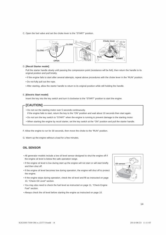
C. Open the fuel valve and set the choke lever to the “START” position.
D. [Recoil Starter model]
Pull the starter handle slowly until passing the compression point (resistance will be felt), then return the handle to its original position and pull briskly.
.noitisop ”NUR“ eht ni revel ekohc eht htiw serudecorp evoba taeper ,stpmetta lareves retfa trats ot sliaf enigne eht fI •
• Do not fully pull out the rope.
• After starting, allow the starter handle to return to its original position while still holding the handle.
E. [Electric Start model]
Insert the key into the key switch and turn it clockwise to the “START” position to start the engine.
F. Allow the engine to run for 30 seconds, then move the choke to the “RUN” position.
G. Warm up the engine without a load for a few minutes.
OIL SENSOR
fi ffo enigne eht tuhs ot dengised rosnes level lio wol a edulcni sledom rotareneg llA • the engine oil level is below the safe operation range.
y fleirb trats lliw ro trats ton lliw enigne eht pu trats gnirud wol si level lio enigne eht fI • and then shut off.
tcetorp ot ffo tuhs lliw enigne eht ,noitarepo gnirud wol semoceb level lio enigne eht fI • the engine.
egap no detcurtsni sa ll fi dna level lio eht kcehc ,noitarepo gnirud spots enigne eht fI • 10, “Check Oil Level” section.
enignE kcehC“ ,11 egap no detcurtsni sa level leuf eht kcehc ot deen osla yam uoY • Fuel” section.
.01 egap no detcurtsni sa enigne eht gnitrats erofeb level lio eht kcehc syawlA •
Oil sensor
.ylsuounitnoc sdnoces 5 revo rotom gnitrats eht nur ton oD •If the engine fails to start, return the key to the “ON” position and wait about 10 seconds then start again.
• Do not turn the key switch to “START” when the engine is running to prevent damage to the starting motor.
• When starting the engine by recoil starter, set the key switch at the “ON” position and pull the starter handle.
[CAUTION]
OPEN
CLOSE
CLOSE
RUNSTART
Choke lever
SGX3500-7500 OM ce_GU7719.indd 14 2014/08/23 11:11:07

15
EN
GL
ISH
FR
AN
ÇA
ISE
ES
PA
ÑO
L
E. Turn the circuit breaker to the “ON” position.
F. Turn on the switch of the appliance.
NOTE:
When the circuit breaker turns off during operation, the circuit is over loaded or the appliance is defective.
Stop the generator immediately, turn off the appliance, check the appliance, check the extension cord and/or generator for overloading or defect and have repaired as necessary by a qualifi ed technician.
TWIST
ON
OFF
USING ELECTRIC POWER
reporp erusne ot teltuo tcerroc eht otni ecnailppa eht gulp ot erus eB .ecnailppa eht fo stnemeriuqer egatlov eht kcehC .Avoltage supply.
B. Turn off the switch/switches of the electrical appliance before connecting to the generator.
C. Insert the plug of the electrical appliance into the receptacle.
tnerruc a ekat ot ton erus eb dna ,elbat gniwollof eht ot gnirrefer desu selcatpecer eht fo egarepma eht kcehC •exceeding the specifi ed amperage.
• Be sure that the total wattage of all appliances does not exceed the rated output of the generator.
D. Turn on the switch of the appliance.
Style Ampere Receptacle AC plug Description
up to 20A NEMA5-20R
NEMA5-20P
GFCI (Ground Fault Circuit Interrupter) Receptacle, duplex
up to 30A NEMAL5-30R
NEMAL5-30P Locking Receptacle
up to 30A NEMAL14-30R
NEMAL14-30P Locking Receptacle
The duplex 120V receptacle is protected by a GFCI (Ground Fault Circuit Interrupter). GFCI shuts off the output current from the duplex 120V receptacle when a ground fault occurs in the generator or the appliance. Please note that other receptacles are not protected by GFCI.
[CAUTION]
• Make sure that the appliance is switched OFF before connecting it to the generator.
• Do not move the generator while it is running.
WARNING
eht otni gulp eht tresni ,ELCATPECER KCOL TSIWT eht morf tuo rewop ekat oT •receptacle, and turn it clockwise to the lock position.
dednuorg si ecived lacirtcele detcennoc eht fi rotareneg eht dnuorg ot erus eB •
WARNING
SGX3500-7500 OM ce_GU7719.indd 15 2014/08/23 11:11:07

16
EN
GL
ISH
FR
AN
ÇA
ISE
ES
PA
ÑO
L
CIRCUIT CONFIGURATION
SGX3500 Operation:
This generator provides two independent 120V power circuits, and each circuit is protected against overload by a magnetic circuit breaker. Circuit 1 is available via one 120V GFCI duplex receptacle (two actual outlets). Up to 15A may be drawn through one or both outlets on the receptacle, independent of any loads on circuit 2.
Circuit 2 is available via a 3-prong 120V locking receptacle*. Up to 15A may be drawn through this circuit independent of any loads on circuit 1.
A 4-prong 120/240V locking receptacle** is also provided. Circuits 1 & 2 are both available via this receptacle, as is a single 240V circuit.
SGX5000 / SGX7500 Operation:
This generator provides two independent 120V power circuits, and each circuit is protected against overload by a magnetic circuit breaker. Circuit 1 is available via one 120V GFCI duplex receptacle (two actual outlets). Up to 20A may be drawn through one or both outlets on the receptacle, independent of any loads on circuit 2.
Circuit 2 is available via a 2nd GFCI Duplex receptacle and a 3-prong 120V locking receptacle*. Up to 20A may be drawn through this circuit independent of any loads on circuit 1.
A 4-prong 120/240V locking receptacle** is also provided. Circuits 1 & 2 are both available via this receptacle, as is a single 240V circuit.
*This NEMA L5-30R receptacle requires a custom cordset – parts can purchased at any local home center or hardware store. Or a pre-made cordset is available from SUBARU that converts this receptacle to work with ordinary 120V plugs.
** This NEMA L14-30R receptacle requires a custom cordset – parts can purchased at any local home center or hardware store. It is typically used for connecting the generator to the home service panel. You must consult a licensed electrician and use a double pole transfer switch when connecting a generator to your home service panel.
If a circuit breaker trips due to excessive load, try to balance the load by moving cords from the most heavily loaded circuit to the more lightly loaded circuit. If the circuit breaker continues to trip, you are exceeding the capacity of the generator.
Circuit 1
Circuit Breaker
GFCIReceptacle120V
Circuit 2 Circuit 1 & 2
Twist LockReceptacle120/240V
GFCIReceptacle120V
Twist Lock Receptacle(SGX5000/SGX7500 Only)120V
SGX3500-7500 OM ce_GU7719.indd 16 2014/08/23 11:11:07

17
EN
GL
ISH
FR
AN
ÇA
ISE
ES
PA
ÑO
L
GFCI RECEPTACLE
After starting the engine, check the GFCI for proper functioning by the following test procedure.
.PIRT drow eht gnisopxe tuo pop lliw nottub TESER ehT .nottub TSET eht hsuP • Power is now off at the outlets protected by the GFCI, indicating that the device is functioning properly.
.naicirtcele de fiilauq a llaC .rotareneg eht esu ton od ,gnitset nehw raeppa ton seod PIRT fI •
.nottub TESER eht hsup ,rewop erotser oT •
STOPPING THE GENERATOR
To stop the engine under normal operating conditions:
.rotareneg eht morf ecnailppa yna tcennocsiD .A
.noitisop ”FFO“ eht ot rekaerb tiucriC eht nruT .B
C. [Recoil Starter model]Turn the engine switch to the “OFF” position.
[Electric Start model]Turn the key switch to the “OFF” position
.noitisop ”ESOLC“ eht ot evlav leuf eht nruT .D
CONNECTING TO A BUILDINGS ELECTRICAL SYSTEM
Connection to a building’s electrical system must be performed by a qualifi ed electrician. The generator power must be isolated from utility power and must adhere to all local codes and ordinances. Note that a double-throw transfer switch must be installed by a qualifi ed electrician to properly isolate the generator from the utility service.
Improper connection to a building’s electrical system can result in back feeding of power through the utility power lines. This presents an electrocution hazard for line workers and others that may come into contact with these lines during an outage. Improper connection can also result in damage to the generator once power is restored. Consult your local utility company or a qualifi ed electrician.
ON
OFF
RESET
TEST
If the RESET button pops out during operation, stop the generator immediately and call a qualifi ed electrician for checking generator and the appliances.
WARNING
ON
OFF
OPEN
CLOSE
CLOSE
SGX3500-7500 OM ce_GU7719.indd 17 2014/08/23 11:11:07

18
EN
GL
ISH
FR
AN
ÇA
ISE
ES
PA
ÑO
L
WATTAGE INFORMATION
Some appliances need a “surge” of energy when starting.
This means that the amount of electrical power needed to start the appliance may exceed the amount needed to maintain its use.
Electrical appliances and tools normally come with a label indicating voltage, cycles / Hz, amperage (amps) and electrical power needed to run the appliance or tool.
Check with your nearest SUBARU Industrial Power Products dealer or service center with questions regarding power surge of certain appliances or power tools.
VOLTAGE DROP IN ELECTRIC EXTENSION CORDS
When a long electric extension cord is used to connect an appliance or tool to the generator, a certain amount of voltage drop or loss occurs in the extension cord which reduces the effective voltage available for the appliance or tool.
Use the shortest extension cord possible.
Nominal cross
sectionA.W.G. Allowable
currentNo.of strands/ strands dia. Resistance Current Amp.
mm2 No. A No./mm Ω/100m 1A 3A 5A 8A 10A 12A 15A
Volt
age
dro
p0.75 18 7 30/0.18 2.477 2.5V 8V 12.5V ─ ─ ─ ─1.27 16 12 50/0.16 1.486 1.5V 5V 7.5V 12V 15V 18V ─2.0 14 17 37/0.26 0.952 1V 3V 5V 8V 10V 12V 15V
3.5 12 to 10 23 45/0.32 0.517 ─ 1.5V 2.5V 4V 5V 6.5V 7.5V5.5 10 to 8 35 70/0.32 0.332 ─ 1V 2V 2.5V 3.5V 4V 5V
niatniam ot dedeen si sa trats ot egattaw emas eht eriuqer setalp toh dna spmal tnecsednacni sa hcus sdaol lacirtcelE • use.
• Loads such as fl uorescent lamps require 1.2 to 2 times the indicated wattage during start-up.
• Loads for mercury lamps require 2 to 3 times the indicated wattage during start-up.
.esu sti dna rotom fo epyt eht no dneped stnemeriuqer rewoP .tnerruc gnitrats egral a eriuqer srotom lacirtcelE • Once enough “surge” is attained to start the motor, the appliance will require only 50% to 30% of the wattage to continue running.
ttaw 000,5 a ,elpmaxe roF .esu gnirud daol rednu gninnur rof egattaw rieht semit 3 ot 2.1 eriuqer sloot cirtcele tsoM • generator can power a 1800 to 4000 watt electrical tool.
eht semit 5 ot 3 deen yehT .trats ot ecrof egral yrev a eriuqer srosserpmoc ria dna spmup elbisrembus sa hcus sdaoL • normal running wattage in order to start.
For example, a 5,000 watt generator would only be able to drive a 1,000 to 1,700 watt pump.
NOTE:The following wattage chart is general guide only. Refer to your specifi c appliance for correct wattage.
To determine the total wattage required to run a particular electrical appliance or tool, multiply the voltage fi gure of the appliance/tool by the amperage (amps) fi gure of same. The voltage and amperage (amps) information can be found on a name plate which normally attached to electrical appliances and tools.
ApplicationsApplicable Wattage(W)
SGX3500 SGX5000 SGX7500
Incandescent lamp, Heater 3200 4500 6700Fluorescent lamp, Electric tool 1750 2500 3700Mercury lamp 1250 1800 2650Pump, Compressor 800 1100 1650
SGX3500-7500 OM ce_GU7719.indd 18 2014/08/23 11:11:08
19
EN
GL
ISH
FR
AN
ÇA
ISE
ES
PA
ÑO
L
HIGH ALTITUDE OPERATION ylsuounitnoc nur eb ot si ti fi enigne siht yfidom relaed stcudorP rewoP lairtsudnI URABUS dezirohtua na evah esaelP •
above 5000 feet (1500 meters). Failure to do so, may result in poor engine performance, spark plug fouling, hard starting, and increased emissions.
ecnamrofrep evorpmi lliw relaed stcudorP rewoP lairtsudnI URABUS dezirohtua na yb noitac fiidom roterubraC • and allow this engine to meet EPA (Environmental Protection Agency) and CARB (California Air Resources Board) emission standards throughout its useful life.
dna taehrevo lliw enigne eht ,os gniod nI .rewol ro teef 0005 ta nur eb ton nac sedutitla hgih rof detrevnoc enigne nA • cause serious damage.Please have an authorized SUBARU Industrial Power Products dealer restore high altitude modifi ed engines to the original factory specifi cation before operating below 5000 feet.
The chart below lists both the standard jet and high altitude jet sizes and SUBARU part numbers
Generator Model Engine Model Standard Jet Size High Altitude Kit High Altitude Jet Size
SGX3500 EX21 #85 278-62551-07 #82.5
SGX5000 EX30 #92.5 291-62552-07 #87.5
SGX7500 EX40 #113 20B-62551-07 #105
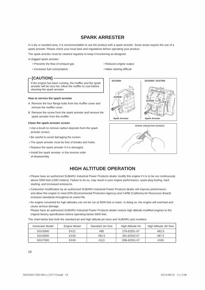
Clean the spark arrester screen
kraps eht morf stisoped nobrac evomer ot hsurb a esU • arrester screen.
• Be careful to avoid damaging the screen.
• The spark arrester must be free of breaks and holes.
• Replace the spark arrester if it is damaged.
redro esrever eht ni ,retserra kraps eht llatsnI • of disassembly.
How to service the spark arrester
dna revoc re flfum eht morf stlob egna fl ruof eht evomeR .Aremove the muffl er cover.
eht evomer dna retserra kraps eht morf wercs eht evomeR .Bspark arrester from the muffl er.
SGX3500
Spark Arrestor
SGX5000 / SGX7500
Spark Arrestor
SCREW
SCREW
SPARK ARESSTER SCREEN
If the engine has been running, the muffl er and the spark arrester will be very hot. Allow the muffl er to cool before cleaning the spark arrester.
[CAUTION]
SPARK ARRESTERIn a dry or wooded area, it is recommendable to use the product with a spark arrester. Some areas require the use of a spark arrester. Please check your local laws and regulations before operating your product.
The spark arrester must be cleaned regularly to keep it functioning as designed.
A clogged spark arrester:
• Prevents the fl ow of exhaust gas • Reduces engine output
• Increases fuel consumption • Make starting diffi cult
SGX3500-7500 OM ce_GU7719.indd 19 2014/08/23 11:11:08

20
EN
GL
ISH
FR
AN
ÇA
ISE
ES
PA
ÑO
L
PERIODIC MAINTENANCEPeriodic maintenance is vital to safe and effi cient operation of your generator. Check the table below for periodic maintenance intervals.
The maintenance schedule indicated in the table is based on the normal generator operation. Should the generator be operated in extremely dusty condition or in heavier loading condition, the maintenance intervals must be shortened depending on the contamination of oil, clogging of fi lter elements, wear of parts, and so on.
MAINTENANCE SCHEDULE
DAILY INSPECTIONBefore running the generator, check the following service items:
• Check fuel level
• Check engine oil level and condition
• Loose or broken bolts and nuts
• Leakage of gasoline or engine oil
• Safe surroundings
• Clean air cleaner element
*Note 1: Initial oil change should be performed after fi rst twenty (20) hours of operation. There after change oil every hundred (100) hours. Before change oil, check for a suitable way to dispose of old oil. Do not pour down into sewage drains, onto garden soil or into open streams. Your local zoning or environmental regulations will give you more detailed instructions on proper disposal.*Note 2: As to the procedures for these items, please refer to the SERVICE MANUAL or consult your nearest service dealer.
Maintenance items Every 8 hours (Daily)
Every 50 hours (Weekly)
Every 200 hours (Monthly)
Every 500 hours
Every 1000 hours
Clean generator and check bolts and nuts ● (Daily)Check for leakage from hoses and fitting ● (Daily)Check and refill engine oil ● (Refill daily up to upper level)Change engine oil (*Note 1) ● (Initial 20 hours) ● (Every 100 hours)
)sruoh 001 yrevE( ●gulp kraps naelC
●renaelc ria naelC
)sruoh 001 yrevE( ●retserra kraps naelC
Replace air cleaner element ●●retlif leuf naelC
●sedortcele dna gulp kraps tsujda dna naelC
Replace spark plug ●●)2 etoN*( daeh rednilyc morf nobrac evomeR
●)2 etoN*( ecnaraelc evlav tsujda dna kcehC
●)2 etoN*( roterubrac tsujda dna naelC
●sehsurb nobrac ecalper dna kcehC
Replace fuel lines ●(Every 2 years)
Overhaul engine (*Note 2) ●)yliaD( ●selcatpecer CA kcehC
)yliaD( ●hctiws enigne kcehC
Replace engine mount ●
SGX3500-7500 OM ce_GU7719.indd 20 2014/08/23 11:11:08
21
EN
GL
ISH
FR
AN
ÇA
ISE
ES
PA
ÑO
L
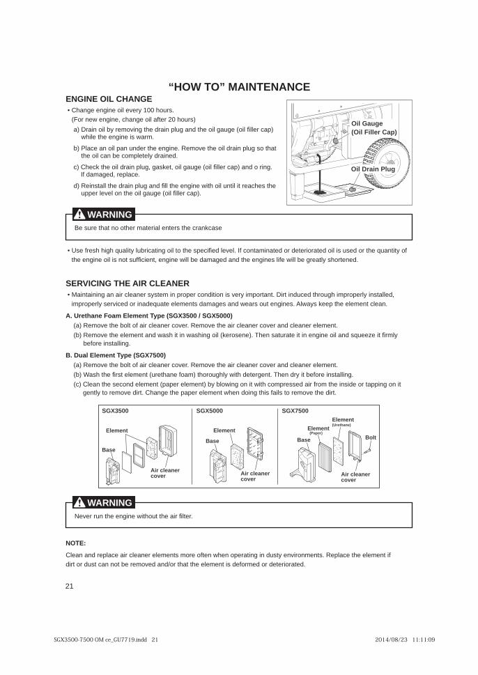
“HOW TO” MAINTENANCEENGINE OIL CHANGE
.sruoh 001 yreve lio enigne egnahC • (For new engine, change oil after 20 hours)
)pac rell fi lio( eguag lio eht dna gulp niard eht gnivomer yb lio niarD )awhile the engine is warm.
taht os gulp niard lio eht evomeR .enigne eht rednu nap lio na ecalP )bthe oil can be completely drained.
.gnir o dna )pac rell fi lio( eguag lio ,teksag ,gulp niard lio eht kcehC )cIf damaged, replace.
eht sehcaer ti litnu lio htiw enigne eht ll fi dna gulp niard eht llatsnieR )dupper level on the oil gauge (oil fi ller cap).
fo ytitnauq eht ro desu si lio detaroireted ro detanimatnoc fI .level de fiiceps eht ot lio gnitacirbul ytilauq hgih hserf esU • the engine oil is not suffi cient, engine will be damaged and the engines life will be greatly shortened.
SERVICING THE AIR CLEANER ,dellatsni ylreporpmi hguorht decudni triD .tnatropmi yrev si noitidnoc reporp ni metsys renaelc ria na gniniatniaM •
improperly serviced or inadequate elements damages and wears out engines. Always keep the element clean.
A. Urethane Foam Element Type (SGX3500 / SGX5000)
(a) Remove the bolt of air cleaner cover. Remove the air cleaner cover and cleaner element.
ylmr fi ti ezeeuqs dna lio enigne ni ti etarutas nehT .)enesorek( lio gnihsaw ni ti hsaw dna tnemele eht evomeR )b(before installing.
B. Dual Element Type (SGX7500)
(a) Remove the bolt of air cleaner cover. Remove the air cleaner cover and cleaner element.
(b) Wash the fi rst element (urethane foam) thoroughly with detergent. Then dry it before installing.
ti no gnippat ro edisni eht morf ria desserpmoc htiw ti no gniwolb yb )tnemele repap( tnemele dnoces eht naelC )c(gently to remove dirt. Change the paper element when doing this fails to remove the dirt.
NOTE:
Clean and replace air cleaner elements more often when operating in dusty environments. Replace the element if dirt or dust can not be removed and/or that the element is deformed or deteriorated.
Element
Air cleaner cover
Base
Element
Air cleaner cover
Base
Element
Air cleaner cover
BoltBase
SGX3500 SGX5000 SGX7500Element(Urethane)
(Paper)
Oil Gauge(Oil Filler Cap)
Oil Drain Plug
Be sure that no other material enters the crankcase
WARNING
Never run the engine without the air fi lter.
WARNING
SGX3500-7500 OM ce_GU7719.indd 21 2014/08/23 11:11:09
22
EN
GL
ISH
FR
AN
ÇA
ISE
ES
PA
ÑO
L
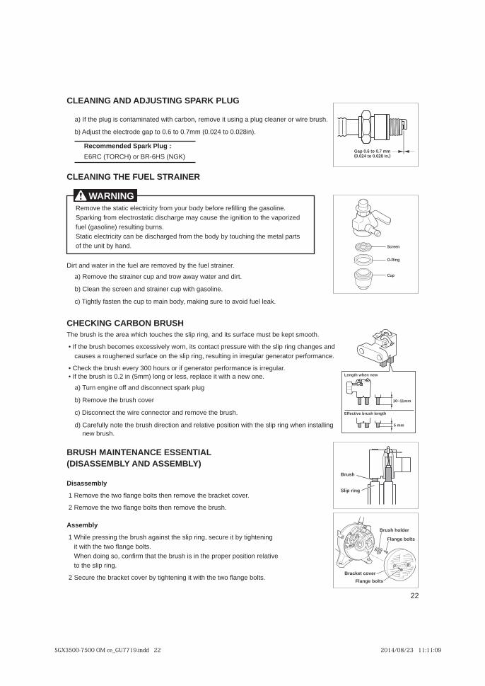
CLEANING AND ADJUSTING SPARK PLUG
a) If the plug is contaminated with carbon, remove it using a plug cleaner or wire brush.
b) Adjust the electrode gap to 0.6 to 0.7mm (0.024 to 0.028in).
Recommended Spark Plug :
E6RC (TORCH) or BR-6HS (NGK)
CLEANING THE FUEL STRAINER
Dirt and water in the fuel are removed by the fuel strainer.
a) Remove the strainer cup and trow away water and dirt.
b) Clean the screen and strainer cup with gasoline.
c) Tightly fasten the cup to main body, making sure to avoid fuel leak.
CHECKING CARBON BRUSHThe brush is the area which touches the slip ring, and its surface must be kept smooth.
dna segnahc gnir pils eht htiw erusserp tcatnoc sti ,nrow ylevissecxe semoceb hsurb eht fI • causes a roughened surface on the slip ring, resulting in irregular generator performance.
.ralugerri si ecnamrofrep rotareneg fi ro sruoh 003 yreve hsurb eht kcehC • .eno wen a htiw ti ecalper ,ssel ro gnol )mm5( ni 2.0 si hsurb eht fI •
a) Turn engine off and disconnect spark plug
b) Remove the brush cover
c) Disconnect the wire connector and remove the brush.
gnillatsni nehw gnir pils eht htiw noitisop evitaler dna noitcerid hsurb eht eton ylluferaC )dnew brush.
BRUSH MAINTENANCE ESSENTIAL (DISASSEMBLY AND ASSEMBLY)
Disassembly
1 Remove the two fl ange bolts then remove the bracket cover.
2 Remove the two fl ange bolts then remove the brush.
Assembly
gninethgit yb ti eruces ,gnir pils eht tsniaga hsurb eht gnisserp elihW 1 it with the two fl ange bolts.When doing so, confi rm that the brush is in the proper position relative to the slip ring.
2 Secure the bracket cover by tightening it with the two fl ange bolts.
5 mm
10~11mm
Effective brush length
Length when new
Flange bolts
Brush holder
Bracket cover
Flange bolts
Slip ring
Brush
Gap 0.6 to 0.7 mm(0.024 to 0.028 in.)
O-Ring
Screen
Cup
Remove the static electricity from your body before refi lling the gasoline.Sparking from electrostatic discharge may cause the ignition to the vaporized fuel (gasoline) resulting burns.Static electricity can be discharged from the body by touching the metal parts of the unit by hand.
WARNING
SGX3500-7500 OM ce_GU7719.indd 22 2014/08/23 11:11:09

23
EN
GL
ISH
FR
AN
ÇA
ISE
ES
PA
ÑO
L
PREPARATION FOR STORAGE
The following procedures should be followed prior to storage of your generator for periods of 6 months or longer.
.enilosag eht gnill fier erofeb ydob ruoy morf yticirtcele citats eht evomeR •Sparking from electrostatic discharge may cause the ignition to the vaporized fuel (gasoline) resulting burns.Static electricity can be discharged from the body by touching the metal parts of the unit by hand.
.er fi tneverp ot knat elbatrop cillatem htiw )enilosag( leuf eht yrrac/erots syawlA •
.enil leuf eht gnitcennocsid yb ylluferac knat leuf morf leuf niarD •
Gasoline left in the fuel tank will eventually deteriorate making engine starting diffi cult.
.roterubrac eht niard osla dna wercs rebmahc tao fl roterubrac eht evomeR •
• Change engine oil.
• Check for loose bolts and screws, tighten them if necessary.
!ROTARENEG NAELC OT REHSAW REWOP A ESU REVEN .htolc tfos htiw ylhguoroht rotareneg naelC •
.noitisop taht ni eldnah gnivael ,tlef si ecnatsiser litnu eldnah retrats lluP •
• Store generator in a well ventilated, low humidity area.
Drain screw
WARNING
SGX3500-7500 OM ce_GU7719.indd 23 2014/08/23 11:11:09
24
EN
GL
ISH
FR
AN
ÇA
ISE
ES
PA
ÑO
L
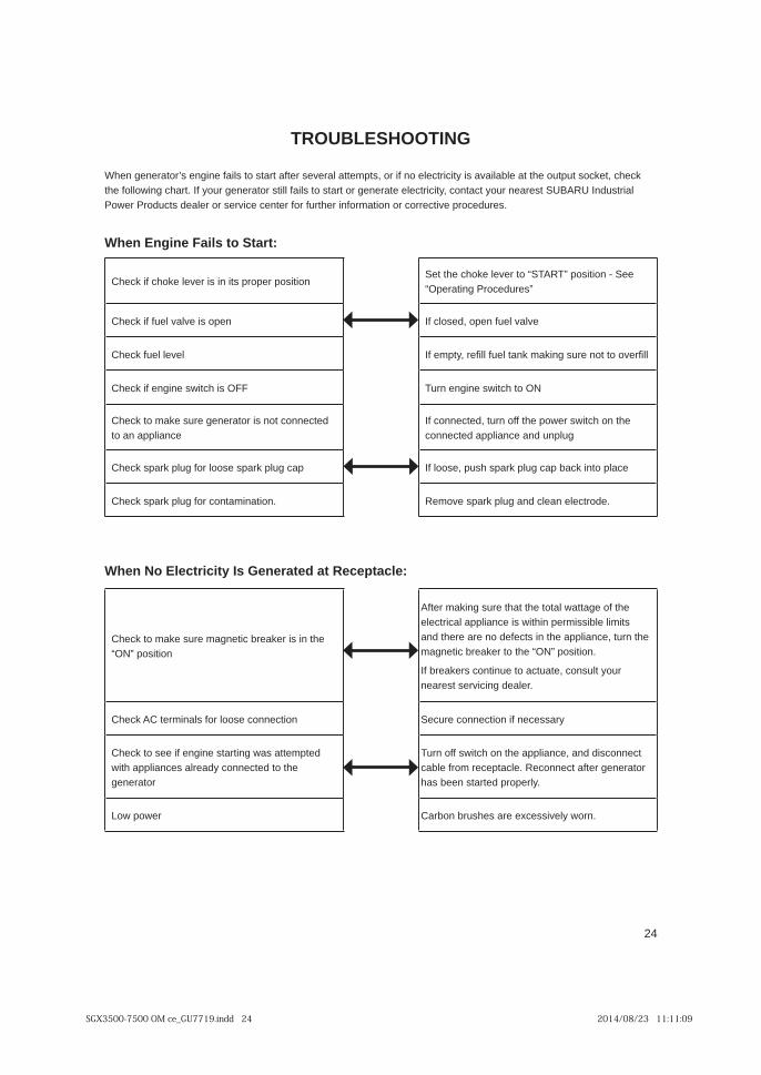
When No Electricity Is Generated at Receptacle:
Check to make sure magnetic breaker is in the “ON” position
After making sure that the total wattage of the electrical appliance is within permissible limits and there are no defects in the appliance, turn the magnetic breaker to the “ON” position.
If breakers continue to actuate, consult your nearest servicing dealer.
Check AC terminals for loose connection Secure connection if necessary
Check to see if engine starting was attempted with appliances already connected to the generator
Turn off switch on the appliance, and disconnect cable from receptacle. Reconnect after generator has been started properly.
Low power Carbon brushes are excessively worn.
TROUBLESHOOTING
When generator’s engine fails to start after several attempts, or if no electricity is available at the output socket, check the following chart. If your generator still fails to start or generate electricity, contact your nearest SUBARU Industrial Power Products dealer or service center for further information or corrective procedures.
When Engine Fails to Start:
Check if choke lever is in its proper positionSet the choke lever to “START” position - See “Operating Procedures”
Check if fuel valve is open If closed, open fuel valve
Check fuel level If empty, refi ll fuel tank making sure not to overfi ll
Check if engine switch is OFF Turn engine switch to ON
Check to make sure generator is not connected to an appliance
If connected, turn off the power switch on the connected appliance and unplug
Check spark plug for loose spark plug cap If loose, push spark plug cap back into place
Check spark plug for contamination. Remove spark plug and clean electrode.
SGX3500-7500 OM ce_GU7719.indd 24 2014/08/23 11:11:09

25
EN
GL
ISH
FR
AN
ÇA
ISE
ES
PA
ÑO
L
WIRING DIAGRAM“THERE IS A PERMANENT CONDUCTOR BETWEEN THE GENERATOR (STATOR WINDING) AND THE FRAME”
SGX3500 (60Hz-120/240V)
AC
win
ding
2
AC
win
ding
1
Grn
/Y
Org
Y/R
Blk
R
R R
R
R
Brn
Brn
Grn
/Y
Grn
/Y
Blk
Ignition coil
Oil sensor switch
Spark plug
Oil sensor unit
Y
Blk
Blu
Blu
Blu
Blu
w w
Grn Grn
ROTO
RST
ATO
R
Slip
ring
Sub
coil
AVR
unit
Eart
h(G
roun
d)te
rmin
al
AC
circ
uit
brea
ker
Brn
Brn
W
Grn
/Y
GE
NE
RA
TO
R
CO
NT
RO
L P
AN
EL
EN
GIN
E
Engi
ne s
witc
h
W WGrn
/YG
rn/Y
30A
W
X
WX
WX
Y
R
W
BrnR W W
W
Grn
/Y
R Blk
R Blk
Hou
r m
eter
W
RW
WX
WX
Brn
Blk
:
Bla
ck
Wir
ing
co
lor
cod
e
Blk
/W :
Bla
ck/W
hite
Blu
:
Blu
eLB
lu
: Li
ght b
lue
Brn
:
Bro
wn
Brn
/W :
Bro
wn/
Whi
teG
rn
: G
reen
Grn
/W :
Gre
en/W
hite
Org
:
Ora
nge
Gry
:
Gra
yR
:
Red
W
: W
hite
Y
: Ye
llow
Grn
/Y :
Gre
en/Y
ello
w
W/B
lk :
Whi
te/B
lack
Pur
:
Pur
ple
SGX3500-7500 OM ce_GU7719.indd 25 2014/08/23 11:11:09

26
EN
GL
ISH
FR
AN
ÇA
ISE
ES
PA
ÑO
L
WIRING DIAGRAM
SGX5000 (60Hz-120/240V)
AC
win
ding
2
AC
win
ding
1
Grn
/Y
Org
Y/R
Blk
R
R R
R
R
Brn
Brn
Grn
/Y
Grn
/Y
Blk
Ignition coil
Oil sensor switch
Spark plug
Oil sensor unit
Y
Blk
Blu
Blu
Blu
Blu
w w
Grn Grn
ROTO
RST
ATO
R
Slip
ring
Sub
coil
AVR
unit
Eart
h(G
roun
d)te
rmin
al
AC
circ
uit
brea
ker
Brn
Brn
W
Grn
/Y
GE
NE
RA
TO
R
CO
NT
RO
L P
AN
EL
EN
GIN
E
Engi
ne s
witc
h
W WGrn
/YG
rn/Y
30A
W
X
WX
WX
Y
R
W
BrnR W W
W
Grn
/Y
R Blk
R Blk
Hou
r m
eter
W
RW
WX
WX
Brn
30A
WX
Blk
:
Bla
ck
Wir
ing
co
lor
cod
e
Blk
/W :
Bla
ck/W
hite
Blu
:
Blu
eLB
lu
: Li
ght b
lue
Brn
:
Bro
wn
Brn
/W :
Bro
wn/
Whi
teG
rn
: G
reen
Grn
/W :
Gre
en/W
hite
Org
:
Ora
nge
Gry
:
Gra
yR
:
Red
W
: W
hite
Y
: Ye
llow
Grn
/Y :
Gre
en/Y
ello
w
W/B
lk :
Whi
te/B
lack
Pur
:
Pur
ple
SGX3500-7500 OM ce_GU7719.indd 26 2014/08/23 11:11:09

27
EN
GL
ISH
FR
AN
ÇA
ISE
ES
PA
ÑO
L
WIRING DIAGRAM
SGX7500 (60Hz-120/240V)
Blu
Blu
Blu
Blu
W W
Grn Grn
AC
win
ding
2
AC
win
ding
1
Grn
/Y
RR
R
nrB
nrB
Grn
/YG
rn/Y
R
W
RO
TO
RS
TAT
OR
Slip
ring
Sub
coi
l
AV
R u
nit
Ear
th(G
roun
d)te
rmin
alB
rn
Brn
Blk
R
R
Blk
Brn
W
Brn
GE
NE
RA
TOR
CO
NT
RO
L P
AN
EL
EN
GIN
E
WW WGrn
/YG
rn/Y
Grn
30A
30A
WX
W
X
WX
WX
Y
R
RR
WW
X
WX
Org Y
/R
Blk
Blk
Blk
Ignition coilOil sensor switch
Spark plug
Oil sensor unit
Y
Bat
tery
Electric starter
Magnetic switch
Charge coil
Key
sw
itch
Blu
Blk
R
LBlu
Grn
/Y
Grn
Grn
/W
Grn
/W
AC
circ
uit
brea
ker
AC
circ
uit
brea
ker
BrnR W
W
W Grn
/Y
R Blk
BlkR
Hou
r m
eter
AC
circ
uit
brea
ker
10A
Fus
e
Blk
:
Bla
ck
Wir
ing
co
lor
cod
e
Blk
/W :
Bla
ck/W
hite
Blu
:
Blu
eLB
lu
: Li
ght b
lue
Brn
:
Bro
wn
Brn
/W :
Bro
wn/
Whi
teG
rn
: G
reen
Grn
/W :
Gre
en/W
hite
Org
:
Ora
nge
Gry
:
Gra
yR
:
Red
W
: W
hite
Y
: Ye
llow
Grn
/Y :
Gre
en/Y
ello
w
W/B
lk :
Whi
te/B
lack
Pur
:
Pur
ple
SGX3500-7500 OM ce_GU7719.indd 27 2014/08/23 11:11:10


