UNC is an Equal Opportunity/Affirmative Action Institution. Ramesh Raskar TR00-027 April 2000 Department of Computer Science CB #3175, Sitterson Hall UNC-Chapel Hill Chapel Hill, NC 27599-3175 U N I V E R S I TA T C A R O L S E P T E N T S I G I L L U M • • • LUX LIBERTAS Shader Lamps Animating Real Objects with Image-Based Illumination Kok-Lim Low Greg Welch
Transcript
UNC is an Equal Opportunity/Affirmative Action Institution.
Ramesh Raskar
TR00-027April 2000
Department of Computer ScienceCB #3175, Sitterson HallUNC-Chapel HillChapel Hill, NC 27599-3175
UN
IVERS I T AT
CAROL
SE
PTENTS
IG I
LL
UM
•
••
LUX
LIBERTAS
Shader Lamps
Animating Real Objects with Image-Based Illumination
Kok-Lim LowGreg Welch
2
Abstract
We describe a new paradigm for three-dimensional computergraphics, using projectors to graphically animate physical objects inthe real world. The idea is to replace a physical object—with itsinherent color, texture, and material properties—with a neutralobject and projected imagery, reproducing the original appearancedirectly on the object. Furthermore the projected imagery can beused to reproduce alternative appearances, including alternateshading, lighting, and even animation. Because the approach is toeffectively “lift” the visual properties of the object into theprojector, we call the projectors
shader lamps
.
Some limited effects have previously been demonstrated alongthese lines for specific applications, however the real challenges torealizing this as a new medium for computer graphics lies inaddressing the problems related to complete illumination of non-trivial physical objects. Our approach offers a very compellingmethod of visualization for a variety of applications includingdynamic mechanical and architectural models, animated or “living”dioramas, artistic effects, entertainment, and even generalvisualization for problems that have meaningful physical shaperepresentations. We present and demonstrate methods for usingmultiple shader lamps
to animate physical objects of varyingcomplexity, from a flower vase, to some wooden blocks, to a modelof the Taj Mahal.
. Reproducing real scenes with a computerhas been a focus of the graphics community for almost as long asthere has been a graphics community. Whether using geometricmodels and physically-based rendering, or image-based models andimage-based rendering, the idea is to “capture” the real world in thecomputer, and then to reproduce it visually. In later years work hasbeen done to explore what is in effect the reversal of thisrelationship, to insert computer graphics in the real world.Primarily this has been done visually for either special effect inmovies, or in real time for
augmented reality.
Most recently there isa new trend to use light projectors to render imagery directly in ourreal physical surroundings. Examples include the
Luminous Room
[Underkoffler97, Underkoffler99a] and the
Office of the Future
[Raskar98]. What we are pursuing here is a more completeextension of these ideas, the incorporation of three-dimensionalcomputer graphics and animation directly into the real world allaround us.
Stimulation and Communication of Ideas.
In general the broadgoals of computer graphics are many, including visualization,intuition, communication, imagination, art, and entertainment.During an invited talk at Microsoft Research in 1996 (associatedwith SIGGRAPH 96) Jim Kajiya noted that
“Computer Graphics is useful not only for augmenting one’sown imagination but [for] stimulating the imagination of others.We can use it to codify, transmit, store, and communicateexperience and ideas. Computer graphics as a medium is onlyjust emerging.” [Kajiya96]
With respect to the stimulation and communication of ideas, we arestruck that despite the many advances in computer graphics,architects and city planners (for example) still resort to buildingphysical models when the time comes to seek client or constituentapproval. (See for example [Howard99].) The architects that wehave spoken with, and many books on the subject, note that while itis true that designers cannot do without CAD tools any more, “It[the computer] cannot replace the actual material experience, thephysical shape and the build-up of spatial relationships.” [Knoll92].Even in this day of computer animation, animators often sculpt aphysical model of a character before making computer models.This was the case with Geri in “Geri’s Game (Pixar AnimationStudios) for example. One reason for these sentiments and practicesis that the human interface to a physical model is the essence of“intuitive.” There are no widgets to manipulate, no sliders to move,
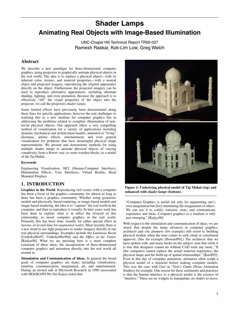
Figure 1: Underlying physical model of Taj Mahal (top) andenhanced with shader lamps (bottom).
Shader Lamps
Animating Real Objects with Image-Based Illumination
UNC-Chapel Hill Technical Report TR00-027
Ramesh Raskar, Kok-Lim Low, Greg Welch
S
HADER
L
AMPS
: A
NIMATING
R
EAL
O
BJECTS
WITH
I
MAGE
-B
ASED
I
LLUMINATION
(299)
3
and no displays to look through (or wear). Instead we walk aroundobjects, moving in and out to zoom, gazing and focusing oninteresting components, all at very high visual, spatial, andtemporal fidelity. We all have a lifetime of experience with thisparadigm. Our goal is to enjoy the many advantages of the naturalphysical interface, in particular the auto-stereoscopic nature ofviewing physical objects, and the richness of computer graphics.
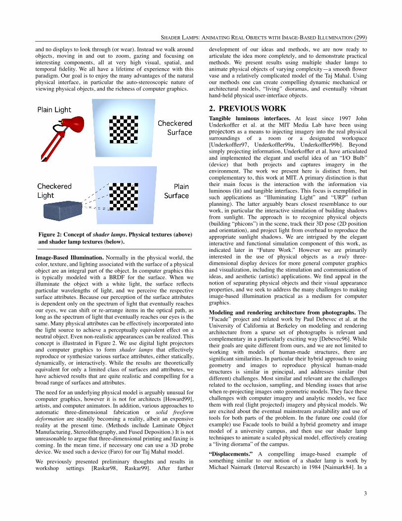
Image-Based Illumination.
Normally in the physical world, thecolor, texture, and lighting associated with the surface of a physicalobject are an integral part of the object. In computer graphics thisis typically modeled with a BRDF for the surface. When weilluminate the object with a white light, the surface reflectsparticular wavelengths of light, and we perceive the respectivesurface attributes. Because our perception of the surface attributesis dependent only on the spectrum of light that eventually reachesour eyes, we can shift or re-arrange items in the optical path, aslong as the spectrum of light that eventually reaches our eyes is thesame. Many physical attributes can be effectively incorporated intothe light source to achieve a perceptually equivalent effect on aneutral object. Even non-realistic appearances can be realized. Thisconcept is illustrated in Figure 2. We use digital light projectorsand computer graphics to form
shader lamps
that effectivelyreproduce or synthesize various surface attributes, either statically,dynamically, or interactively. While the results are theoreticallyequivalent for only a limited class of surfaces and attributes, wehave achieved results that are quite realistic and compelling for abroad range of surfaces and attributes.
The need for an underlying physical model is arguably unusual forcomputer graphics, however it is not for architects [Howard99],artists, and computer animators. In addition, various approaches toautomatic three-dimensional fabrication or
solid freeformdeformation
are steadily becoming a reality, albeit an expensivereality at the present time. (Methods include Laminate ObjectManufacturing, Stereolithography, and Fused Deposition.) It is notunreasonable to argue that three-dimensional printing and faxing iscoming. In the mean time, if necessary one can use a 3D probedevice. We used such a device (Faro) for our Taj Mahal model.
We previously presented preliminary thoughts and results inworkshop settings [Raskar98, Raskar99]. After further
development of our ideas and methods, we are now ready toarticulate the idea more completely, and to demonstrate practicalmethods. We present results using multiple shader lamp
s
toanimate physical objects of varying complexity—a smooth flowervase and a relatively complicated model of the Taj Mahal. Usingour methods one can create compelling dynamic mechanical orarchitectural models, “living” dioramas, and eventually vibranthand-held physical user-interface objects.
2. PREVIOUS WORK
Tangible luminous interfaces.
At least since 1997 JohnUnderkoffler et al. at the MIT Media Lab have been using
projectors
as a means to injecting imagery into the real physicalsurroundings of a room or a designated workspace[Underkoffler97, Underkoffler99a, Underkoffler99b]. Beyondsimply projecting information, Underkoffler et al. have articulatedand implemented the elegant and useful idea of an “I/O Bulb”(device) that both projects and captures imagery in theenvironment. The work we present here is distinct from, butcomplementary to, this work at MIT. A primary distinction is thattheir main focus is the interaction with the information vialuminous (lit) and tangible interfaces. This focus is exemplified insuch applications as “Illuminating Light” and “URP” (urbanplanning). The latter arguably bears closest resemblance to ourwork, in particular the interactive simulation of building shadowsfrom sunlight. The approach is to recognize physical objects(building “phicons”) in the scene, track their 3D pose (2D positionand orientation), and project light from overhead to reproduce theappropriate sunlight shadows. We are intrigued by the elegantinteractive and functional simulation component of this work, asindicated later in “Future Work.” However we are primarilyinterested in the use of physical objects as a
truly
three-dimensional display devices for more general computer graphicsand visualization, including the stimulation and communication ofideas, and aesthetic (artistic) applications. We find appeal in thenotion of separating physical objects and their visual appearanceproperties, and we seek to address the many challenges to makingimage-based illumination practical as a medium for computergraphics.
Modeling and rendering architecture from photographs.
The“Facade” project and related work by Paul Debevec et al. at theUniversity of California at Berkeley on modeling and renderingarchitecture from a sparse set of photographs is relevant andcomplementary in a particularly exciting way [Debevec96]. Whiletheir goals are quite different from ours, and we are not limited toworking with models of human-made structures, there aresignificant similarities. In particular their hybrid approach to usinggeometry and images to reproduce physical human-madestructures is similar in principal, and addresses similar (butdifferent) challenges. Most similar and relevant are the challengesrelated to the occlusion, sampling, and blending issues that arisewhen re-projecting images onto geometric models. They face thesechallenges with computer imagery and analytic models, we facethem with real (light projected) imagery and physical models. Weare excited about the eventual mainstream availability and use oftools for both parts of the problem. In the future one could (forexample) use Facade tools to build a hybrid geometry and imagemodel of a university campus, and then use our shader lamptechniques to animate a scaled physical model, effectively creatinga “living diorama” of the campus.
“Displacements.”
A compelling image-based example ofsomething similar to our notion of a shader lamp
is work byMichael Naimark (Interval Research) in 1984 [Naimark84]. In a
San Francisco Museum of Modern Art exhibit titled“Displacements,” Naimark used projectors to present some in-place image-based modeling and rendering content. The image-based content was captured by using a rotating movie camera tofilm the contents of a living room, replete with furniture andpeople. The room and furniture were then painted completelywhite (neutral), and the captured imagery was re-projected backonto the walls using a rotating projector that was preciselyregistered with the original camera. The most relevant aspect ofthis work is the explicit separation and then later merging of thephysical and visual properties of a real scene. We are interested inpursuing the full exploitation of this idea, including themanipulation of the visual properties, and in solving the challengesrelated to multiple overlapping sources of illumination.
Theater and entertainment
. Theatrical scene (set) and lightingdesigners have used colored and even “textured” lighting tostimulated moods and ideas, and to simulate the effects of reallighting in a scene. In fact, the use of 3D objects as graphicaldisplay devices is similar to theater in that often seeing the contentin person, with the rich physical and optical characteristics, is farmore compelling than seeing a 2D version through conventionaldisplay devices. Of course the computer graphics special effectsdemonstrated in modern movies today offer an example of therichness and flexibility generally not possible in the physicaltheater. In fact, with the realization of our methods, it is reasonableto consider the inclusion of some computer-generated specialeffects directly on physical objects in live theater, thus realizingsome of the richness of each medium. A limited but compelling(and possibly seminal) example of this idea is the use of projectorsto animate artificial human heads in the Walt Disney World“Haunted Mansion” attraction. Projected imagery animates fourneutral busts of singing men, and a patented projector and fiber-optic setup animates the head of the fictional fortune teller“Madame Leota” inside a real crystal ball [Liljegren90].
On a more physically grand scale, projectors have recently beenused to render a variety of lighting and projected imagery on a verylarge architectural scale. For example, in 1952 Paul Robert-Houdinused sounds and colored lights on a building for nighttimeentertainment. The most well-known modern realization of thisidea is the Son et Lumiere (light show) at/on the Blois castle in theLoire Valley (France). In addition the medium is now being usedelsewhere around the world at sites such as the Forum (Rome), theParthenon (Athens); Greenwich Palace; Independence Hall(Philadelphia); the Pyramids of Giza (Cairo); the Red Fort (Delhi);and the ruins of Teotihuacán (near Mexico City); Most recentlydynamic imagery was and the Millenium celebration at the threePyramids at Giza in Cairo (Egypt).
Finally, to realize the general application of this technique onemust, among other things, have a method for pre-warping imageryto “fit” the physical object so that it appears correct to local
viewers. It is worthy to note that this problem is very similar to thatfaced by Julie Dorsey et al. [Dorsey91] in trying to model theappearance of theatrical backdrops so that they appear correct fromthe audience’s perspective. We use techniques that build on this(similar to [Raskar98]) to render onto the potentially very non-planar surfaces of physical objects, and new techniques to addressthe occlusion, sampling, and blending issues.
3. THE RENDERING PROCESS
The appearance of a surface is decided by the radiance at thatsurface. Hence, it should be possible to reproduce the sameappearance on neutral surfaces by rearranging the incidentradiance. This result should not be surprising, as that is what weare used to typically with projector screens. Indeed, in thefollowing derivation we will see that reproducing the surfaceappearance on neutral surfaces is equivalent to rendering the imagefor a given viewer location and warping it to render from theprojector lamp with intensity modifications.
First, let us consider the rendering equation, which is essentially ageometrical optics approximation as explained in [Kajiya86]. Theradiance at visible surface point ( ) in the direction thatwould reach the observer of a physical realization of the scene is
(1)
where
and is the geometry term (visibility and distance), is the emitted radiance of the point (non-zero only for
light sources), and is the bidirectional reflectiondistribution function (BRDF) for the point. The integral in
accounts for all reflection of incident radiance from solid angles . Radiance has dimensions of
energy per unit time, area and solid angle.
Treating the projector lamp as a point emitter, the radiance due todirect projector illumination at the same surface point but withdiffuse reflectance is given by,
(2)
where = radiance of projector in the direction, = surface diffuse reflectance factor at , is the incident direction at the surface point . The
radiance is converted into a discretized pixel value using filteringand tone representation.
Clearly, we can reproduce equivalent radiance for a given viewerlocation, by solving Eqn. (2) for :
(3)
Using any rendering technique, we can first compute ata surface point for the given viewer location, and then compute thecorresponding projector image intensities using the equationabove. This is somewhat unusual as normally intensities arecomputed as an image seen by the viewer and not associated withsurface points in object-space. The method of warping this imageso that it appears to be captured from the lamp’s viewpoint is wellknown in the image-based rendering literature [Chen93][Mcmillan95]. Thus, in one way, this is equivalent to rendering and
Figure 3: From the Walt Disney World “Haunted Mansion,”still cells of animated faces projected onto neutral busts (left),and Madame Leota’s head (right).
x θ φ,( )
L x θ φ, ,( ) g x θ φ, ,( ) Le x θ φ, ,( ) h x θ φ, ,( )+( )=
h x θ φ, ,( ) Fr x θ φ θi φi, , , ,( )Li x θi φi, ,( ) θi( )cos ωidi∫=
g x θ φ, ,( )Le x θ φ, ,( )
Fr x θ φ θi φi, , , ,( )
h x θ φ, ,( )Li x θi φi, ,( ) ωid
L' x θ φ, ,( ) g x θ φ, ,( )ku x( )LP x θP φP, ,( ) θP( )cos=
LP x θP φP, ,( )θP φP,( ) ku x( ) x( )θP φP,( ) x( )
LP
LPL x θ φ, ,( )
ku x( ) θP( )cos--------------------------------- for ku 0> .=
L x θ φ, ,( )
S
HADER
L
AMPS
: A
NIMATING
R
EAL
O
BJECTS
WITH
I
MAGE
-B
ASED
I
LLUMINATION
(299)
5
warping the image followed by intensity correction. For achanging viewer location, view-dependent shading under staticlighting conditions, can also be implemented[Debevec98][Levoy97][Gortler96]. However, the warping can beavoided by realizing that the display medium is the same as theobject. A modification of the general rendering method is required:the eye-point for shading calculations is at a different location thanthe center of perspective projection. The visibility calculations canbe performed without any modification from the projector lamp’sviewpoint because the viewer naturally sees only the physicallyunoccluded parts of the real objects.
Since we want to animate the physical objects, we are forced to usereal-time techniques. In current real-time 3D rendering APIs, thesolution to the general rendering equation is approximated. TheBRDF computation is divided into view-dependent specular, andview-independent diffuse and ambient terms. View-independentshading calculations can be done by assuming the user and theprojector lamp are at the same location. Rendering of shadows isalso view-independent (although not supported directly), and theyare computed using the traditional two-pass shadow-buffertechnique. For view-dependent shading, such as specularhighlights, however there is no existing support. Appendix Idescribes a simple modification that allows rendering view-dependent shading without additional cost.
3.1 Secondary ScatteringShader lamps are limited in the type of surface attributes that canbe reproduced. In addition, since we are using neutral surfaces,secondary scattering is unavoidable and can potentially affect thequality of the results. On the other hand, the secondary scatteringcan be used to our advantage in cases where underlying virtualobject is purely diffuse. The geometric relationships, also knownas form factors, among parts of the physical objects are naturallythe same as that among parts of the virtual object. Suppose, weconsider only the direct illumination during view-independentshading calculations (as usually is the case with real-time APIs).After the appropriate intensity correction Eqn. (3), we will be ableto generate the correct radiance at patch due to differentvirtual light sources
where is the diffuse reflectance, is the radiance of virtuallight sources and is the form factor between the light sourcesand this patch. However due to secondary scattering, if neutral
surfaces have diffuse reflectance , the perceived radianceincludes the secondary scattering due to the patches:
.
Li1 eyeθ
x
L
Li2
eye θ2
θ1
x
L’
Llampθθ lampθP
LP
Figure 4: (left) The radiance at a point in the direction (right) The radiance as a result of illumination from a projec-tor lamp. By rearranging the parameters in the optical path,the two can be made equal.
θ φ,( )
i m
Bi-direct kdiBmFi m,
m∑=
kd BmFi m,
a
b
c
Figure 5: (a) The underlying physical object is a white diffusevase (b) The vase can be effectively ‘painted’ by projecting animage with view-independent diffuse shading, textures andintensity correction. Some view-dependent effects such asspecular highlights are generated for a given user location bymodifying reflectance properties of the graphics model.(c) The same vase with different material properties.
kun
Bi-actual kdiBmFi m,
m∑ ku BnFi n,
n∑+=
SHADER LAMPS: ANIMATING REAL OBJECTS WITH IMAGE-BASED ILLUMINATION (299)
6
This is very close to the radiosity solution for non-emittersconsidering all the light sources and patches,
Thus, the secondary contribution from neutral surfaces is notaccurate but still results in the ‘spilling’ of colors on neighboringparts of the physical objects. Figure 6 shows green paper with spillover, with and without illumination.
3.2 Illumination of All Visible SurfacesA complete illumination of physical object clearly needs more thanone lamp. One may wonder, given a physical object, what is a goodset of viewpoints for the lamps, so that every visible surface isilluminated by at least one lamp. This problem is addressed by[Stuerzlinger99], where he finds the set of viewpoints for camerasso that every visible part of every surface is imaged at least once,using a hierarchical visibility algorithm. The problem ofdetermining an optimal set of viewpoints is NP hard and is relatedto the art gallery problem [O’Rourke87] known in the field ofcomputational geometry.
4. METHODSThe image-based illumination of physical objects has beenexplored by many. However, the techniques are still very limitedand it is treated as a problem of 2D registration between a singleimage and its projection on an object. The overall process is very
well-defined in advance and used in large entertainment centers ortheaters. With the advent of digital light projectors and real-time3D graphics, we believe that some additional tools can make thetask of animating neutral physical objects as simple as renderingon a computer screen.
Some major challenges have kept such efforts to only large-scaleimplementations. Many people consider the task of aligning theimages correctly with the physical object to be very cumbersome.This is usually solved by tedious electro-mechanical adjustmentsand then kept in place by rigid mechanical construction. The otherimportant problem is dealing with shadows due to self-occlusionwith respect to the projectors. We treat the problem of alignment asessentially a problem of 3D calibration of a pin-hole projectiondevice. We illuminate the shadowed parts of the object by addingmore projectors and then address the issue of merging overlappedimages from multiple projectors.
4.1 Authoring and AlignmentOne of the important tasks in achieving compelling visualization isto create association between the physical objects and the graphicsprimitives that will enhance those objects when projected. We needthe physical object as well as its geometric 3D representation. Formost applications, the physical object is already available but notnecessarily its 3D graphics model. As mentioned in Section 1,many hardware and software solutions are now available to scan3D objects and create highly detailed, textured graphics models.On the other hand, when the 3D definition is available, a singlecolored physical model can be created using 3D printers. In ourcase we used a touch probe 3D scanner to record key features andthen used a commercial 3D modeling tool to assign textures andmaterials. The authoring can also be done interactively by‘painting’ directly on top of the physical objects. As demonstratedin the video, the result of user interaction is projected on theobjects and also stored on the computer. Ideally, a moresophisticated user interface would be used to create and editgraphics primitives of different shape, color and texture. Then auser may be able to make decisions about, for example, whichtexture image should be used for the face of a building model, orwhat color distribution will look better for a physical object.
Calibrating a projector with respect to the physical objects involvesfinding its internal parameters and the rigid transformationbetween the coordinate system of the objects and the projector.This is a classical computer vision problem [Faugeras93]. For ourdemonstrations, we take a set of fiducials with known 3D locationson the physical object and then find corresponding projector pixelsthat illuminate them. This allows us to compute a 3x4 perspectiveprojection matrix up to scale, which is decomposed to find theinternal and the external parameters of the projector. The renderingprocess uses the same internal and external parameters, so that theprojected images are registered with the physical objects.
4.2 Intensity CorrectionThe intensity of the rendered image is modified to take intoconsideration the reflectance of the neutral surface and the localorientation of the surface with respect to the projector. To computethe correction using the cosine term at each projector pixel, weneed the direction of the normal at the surface illuminated by thepixel. For polygonal graphics models, the surface normal isavailable only at the vertices. We instead use a simpleapproximation inside our rendering program by illuminating awhite diffuse version of the graphics model with a virtual whitelight placed at the location of projector lamp. The resultantintensities are smooth across curved surfaces due to shading
m n
Bi-intended kdiB jFi j,
j∑=
kdiBmFi m,
m∑ BnFi n,
n∑+
=
a
b
Figure 6: (a) A green paper illuminated with white light(b) The white diffuse surface on the right is illuminated withgreen light. In this special case, the secondary scattering offthe white surface below is similar for both parts.
SHADER LAMPS: ANIMATING REAL OBJECTS WITH IMAGE-BASED ILLUMINATION (299)
7
interpolation and directly proportional to the cosine of the anglebetween view vector and surface normal. For angles greaterthan sixty degrees, the correction ( ) is greater than afactor of two. To use the limited dynamic range of the projectorsmore efficiently, we do not illuminate surfaces facing at anglesgreater than sixty degrees. This avoids the low sampling rate ofprojected pixels on oblique surfaces and also minimizes themisregistration effects due to the errors in geometric calibration.During the calculations to find overlap regions, described below,the highly oblique surfaces are considered not illuminated.
4.3 Occlusions and OverlapsA major problem with using projectors is the presence of shadowsdue to self-occlusion on the physical object. A single projector canonly partially illuminate a closed object. Using additionalprojectors is an obvious choice. However this leads to the moredifficult problem of seamlessly merging images from multipleprojectors. This situation is analogous to image based renderingtechniques, where warping a single depth-enhanced image createsdis-occlusion artifacts. When multiple source images are warped tothe target image, the color assigned to a pixel is derived from eithera single image (where they overwrite each other) or as a weightedcombination of pixels from multiple images. With projectors theresulting intensity is always the sum of all intensities and there isno ‘winning’ pixel.
The luminance in the overlap region may be much greater than thatin regions illuminated by only one projector. Thus in addition togeometric alignment between projected images, it is also necessaryto achieve intensity normalization. The problem of generatingseamless images using multiple projectors has been explored forlarge wide-field-of-view displays [Panoram] [Trimensions][Raskar99], as well as two-dimensional arrays of flat projections[Humphreys99] [Czernuszenko97]. In such cases, the overlapregion is typically a (well-defined) contiguous region on displaysurface as well as in each projectors frame buffer. The intensity ofprojector pixels is weighted using feathering (also known asintensity roll-off or soft-edge) techniques so that the overlappingimages blend to create a single seamless image.
However, in our case, the physical model is usually made up ofnon-convex objects or a collection of disjoint objects resulting inoverlap regions that are fragmented in each projector’s framebuffer. Traditional feathering techniques weight the pixelintensities proportional to the distance to the nearest boundary (orinvisible) pixel in the source image. The weights multiply theintensities in the final rendered image and range between [0, 1.0].The pixels near the boundary of a source image contribute verylittle, so that there is a smooth transition to the next source image.This works well only when the target image is a single continuoussurface at and around the overlap. Some examples are the finalimages in photo-mosaics [Szeliski97] and tiled displays on planaror curved surfaces [Panoram] [Trimensions][Raskar99].
We describe a new modified feathering algorithm for assigningintensity weights when the surfaces at which the source images aremerged may have depth discontinuities. This blending techniquecan also be used in image based rendering to determine thecontribution of pixels in each image to the novel view.
Our algorithm is based on the following guidelines:
1. The sum of the intensity weights of the corresponding projector pixels is one so that the intensities are normal-ized;
2. The intensity contribution of a projector along a surface on the physical object changes smoothly so that projec-tors which differ in color properties do not create visi-ble discontinuity in images; and
3. The distribution of intensity weights for a projector within its framebuffer is smooth so that small errors in calibration or mechanical variations do not result in sharp edges.
When the illuminated surface is continuous, the conditions (2) and(3) are essentially the same. Note that it is not always possible tosatisfy the conditions (2) or (3) even for smooth continuoussurfaces. So they are used only as guidelines. For surfaces withdepth discontinuity with respect to any projector, it is moreimportant to ensure (2) than (3). This is because, in practice, it isrelatively easy to achieve (or maintain) precise geometriccalibration but difficult to ensure color equality among a set of
α1 α( )cos( )⁄
Figure 7: Intensity weights using traditional featheringmethod (a) Simple intensity ramps on planar overlap createsmooth transitions.
(b) Concave object in overlap region, the weight at point gdue to projector A is not zero creating a large change in A’scontribution (c) By considering depth layers in the modifiedfeathering technique, intensities due to each projectorchange smoothly on real surfaces.
a
b
c
SHADER LAMPS: ANIMATING REAL OBJECTS WITH IMAGE-BASED ILLUMINATION (299)
8
projectors. Broadly, the three guidelines essentially suggestsolving the feathering problem at each ‘depth layer’ separately. Adepth layer corresponds to contiguous regions in the depth bufferwith no discontinuity between any neighboring pixels of theregion. Such a solution will avoid feathering intensities acrossdepth discontinuities. Traditional feathering methods use thedistance to the nearest boundary (i.e. zero contribution) pixel tofind the weight. Instead, we first find pixels corresponding toregions illuminated by a single projector and assign an intensityweight of 1.0. Then, for the remaining pixels, the basic idea behindour technique is to find the shortest distance to a pixel region withweight 1.0 and which is also in the same depth layer. The assignedweight for this pixel is inversely proportional to this distance.
For a practical implementation we use two buffers, an overlapbuffer and a depth buffer. For the sake of simplicity, we will use theword ‘pixel’ to mean the pixel in the framebuffer as well as the 3Dpoint illuminated by the pixel. In the overlap buffers, integer valuesare assigned to a pixel depending on how many pixels from otherprojectors overlap with this pixel. If the pixel does not illuminateany useful region, the value is zero. If no other projectors overlapwith this pixel, the value is one. The overlap regions (i.e. overlapcount of two or more) are computed using the traditional shadow-buffer algorithm that finds pixels in the current view lit by a pointlight source. The light sources in this case are the other projectorlamps. The depth buffer simply stores the resultant depth valueswhen the graphics model of the physical object is rendered. Firstwe find overlap boundaries in overlap buffer between pixels withvalue 1 and pixels with value more than 1. In the depth buffer, wefind boundaries between pixels with a large depth difference. Theshortest distance (in pixel units) for each pixel in the overlapregion is then found by finding the euclidean distance to thenearest pixel in the region of count 1, ignoring paths that cross overa depth discontinuity. For some pixels in the overlap region, nopixel of count 1 is found in the same depth layer and the distance isset to a large value. Finally, using the traditional 3D warpingtechnique, we find all corresponding pixels that illuminate thesame 3D point and assign a weight inversely proportional to thecomputed shorted distance. For example, if corresponding pixels
and in two overlapping projectors and have assigneddistance of and , then is assigned the weight
and similarly is assigned the weight
.
5. ISSUESToday’s projectors have a limited depth of field and hence cannotcreate images that remain in focus over the a large physical object.The problem due to secondary scattering cannot be completelyavoided which makes reproducing the behavior of surfaces withvery low reflectance is difficult. The same problem is made evenworse by the ‘black level’ of the projectors i.e. the non-zeroillumination when the rendered pixel color is black. A majorproblem during implementation is the non-linearity of projectorillumination with respect to the values in the framebuffer. Wecompensate for the non-linearities with a gamma factor in theweighting functions, but that does not solve the problemcompletely.
In terms of user interaction, shadows of the user on the projectedsurface can be disturbing. However, the method has the greatadvantages of not requiring the user to wear stereo-glasses or head-mounted displays.
6. IMPLEMENTATIONFor the setup, we used two Sony VPL6000U projectors displayingat 1024x768 resolution. The OpenGL rendering programs run on aWindows NT PC with Wildcard graphics card. The vase is made upof clay and is approximately 12 cm x 12 cm x 35 cm. The TajMahal model is wooden and spray painted white. The dimensionsare approximately 70 cm x 70 cm x 35 cm. Both objects werescanned with a 3D touch probe sensor which gives readings withan accuracy of 0.5 mm. Since the vase is a surface of revolution,we recorded points on the curve and created a surface model usingRhino3D modeling package. The Taj Mahal was scanned in byrecording key features. (We collected approximately 100 points forthe Taj Mahal, and 25 for the vase.) The vase model is made up of7000 triangles. The Taj Mahal model is made up of 21,000triangles and 15 texture maps. For the specular highlight effects,we used the Origin Instruments Dynasight optical tracking systemto find the viewer location.
The projectors are calibrated by finding pixels that illuminateknown 3D fiducials on the model. Selected approximately 20points on the model. Then we align a projected cross-hair bymoving it in the projector image-space. The 3x4 perspectiveprojection matrix and its decomposition into internal and externalparameters of the projector are computed using Matlab. The
Pa Pb A Bda db Pa
1 da⁄
1 da⁄ 1 db⁄+-------------------------------
db
da db+-----------------=
Pb
da
da db+-----------------
Figure 8: The vase is illuminated by two projectors. (a-b)Images rendered by first and second projectors. (c-d) The intensity weight images, including elimination of ob-lique parts, and correction for surface orientation and over-lap (e-f) Final projected images after intensity normalization.
SHADER LAMPS: ANIMATING REAL OBJECTS WITH IMAGE-BASED ILLUMINATION (299)
9
rendering process uses these parameters so that the projectedimages are registered with the model. It takes less than five minutesto calibrate each projector. Typically the maximum re-projectionerror was less than two pixels and the images from the twoprojectors appear geometrically aligned on the physical model.The intensity weights for projector pixels are computed duringpreprocessing and it takes approximately 10 second for eachprojector. The intensities during rendering are modified usingalpha blending available in the graphics hardware. More detailsand high resolution colored images are available at the anonymouswebsite http://members.xoom.com/shaderlamps.
7. POSSIBILITIESWe believe the potential of shader lamps extends much beyondwhat we have described or even imagined. While we have focussedon techniques for creating image based illumination withtraditional computer graphics, additional technologies such astracking, vision-based recognition and smart building blocks cantake this medium into new territories.
In the simplest form, shader lamps can be used to dynamicallychange the color of day-to-day objects or add temporary markingson them. For example, engineers can mark the areas of interest likedrilling locations without affecting the physical surface. Asdemonstrated by [Underkoffler99b], city planners can movearound physical scaled blocks and visualize global effects such asshadows and wind patterns in 3D. For stage shows, we can changenot just the backdrops, but also simulate seasons or aging of theobjects in the scene. In the video, we show how motion can besimulated out of stationery objects by changing the texture mappedon the objects. Interesting non-photo-realistic effects can also begenerated.
With simple head tracking, we have demonstrated how a vasemade of clay can appear to be made of metal or plastic. It is easy torender other view dependent effects such as reflections. Theconcept can be extended to much larger setups. Sculptures oftenmake clay models of large statues before they create a mold. It maybe useful for them to visualize how the geometric form they havecreated will look with different material or under differentconditions in context of other objects. We believe image basedillumination can be very effectively used in movie studios whereminiature models are painstakingly built and then updated withfine detail. With tracked motion camera, it is even possible toproject the silhouettes of moving virtual characters, so that thepost-processing task of inserting computer graphics characters canbe simplified.
When multiple people want to simultaneously want to look theenhanced object, we can track and illuminate moving physical
objects with registered colors and textures. For example inshowroom windows or on exhibition floors, one can show arotating model of the product in changing colors or with differentfeatures enhanced.
Our video shows a demonstration of interactive spray painting ontop of real objects. A useful tracked input device could be a “paintbrush” that allows natural haptic feedback. The result of theinteraction is then stored to make it a truly 3D paint system. We arealso excited about a 2-handed 3D modeling and 3D painting setupwhere user's viewpoint, input device and a course shaped object(such as a sphere) are tracked. The user can literally create and addsurface properties to a virtual object that's always registered withthe sphere.
8. CONCLUSIONWe have described a new paradigm for 3D computer graphics,which involves light projectors and physical objects to generaterich detailed images directly in the user’s world. Although themethod is limited when compared to traditional graphics renderedon computer screens, it offers a new way of interacting withsynthetic imagery. A rendering process essentially involves user’sviewpoint, shape of the graphics objects, reflectance properties andillumination. Traditional computer graphics or head-mountedaugmented reality generates the result for all these elements at areduced temporal (frame rate) or spatial (pixel) resolution. As wehave seen, the concept of shader lamps attempts to keep theviewpoint and shape at the best resolution and only the added colorinformation is at a limited resolution. We believe the visualizationmethod is compelling for a variety of applications includingarchitectural design, art and entertainment.
9. REFERENCES[Brooks99] Fred Brooks, personal communication.[Chen93] Chen, S. E. and L. Williams. “View Interpolation from
Image Synthesis,” in SIGGRAPH 93, pp 279-288, July 1993.[Czernuszenko97] M. Czernuszenko, D. Pape, D. Sandin, T.
DeFanti, L. Dawe, and M. Brown. The ImmersaDesk and InfinityWall Projection-Based Virtual Reality Displays. In Computer Graphics, May 1997.
[Debevec96] Paul E. Debevec, Camillo J. Taylor, and Jitendra Malik. “Modeling and Rendering Architecture from Photo-graphs,” in SIGGRAPH '96, August 1996.
[Debevec98] Paul Debevec, Yizhou Yu and George Borshukov, Efficient View-Dependent Image-Based Rendering with Pro-jective Texture-Mapping, Proc. of 9th Eurographics Workshop on Rendering, Vienna, Austria, June, 1998
[Dorsey91] Dorsey, Julie O’B., Fransco X. Sillion, Donald Green-berg. 1991. “Design and Simulation of Opera Lighting and Projection Effects,” SIGGRAPH 91 Conference Proceedings, Annual Conference Series, ACM SIGGRAPH, Addison-Wes-ley, pp. 41-50, 1991.
[Faugeras93] O. Faugeras. Three-Dimensional Computer Vision: A Geometric Viewpoint. MIT Press, Cambridge, Massachusetts, 1993.
[Gortler96] S. J. Gortler, R. Grzeszczuk, R. Szeliski and M.F. Cohen, "The Lumigraph", in SIGGRAPH96, August 1996
[Howard99] HowardModels.com, 7944 Central Avenue, Unit 3, Toledo, Ohio 43617. Available at http://www.howardweb.com/model/index.html [cited January 9, 2000].
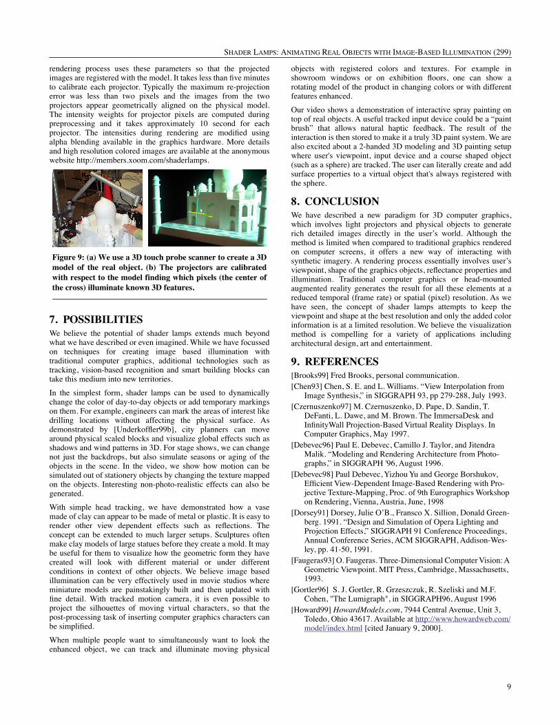
Figure 9: (a) We use a 3D touch probe scanner to create a 3Dmodel of the real object. (b) The projectors are calibratedwith respect to the model finding which pixels (the center ofthe cross) illuminate known 3D features.
SHADER LAMPS: ANIMATING REAL OBJECTS WITH IMAGE-BASED ILLUMINATION (299)
10
[Humphreys99] Humphreys, Greg and Pat Hanrahan. “A Distrib-uted Graphics System for Large Tiled Displays” in Proceed-ings of IEEE Visualization 99, San Fransisco, CA, October 24-29, 1999.
[Kajiya86] KAJIYA, J. T. The rendering equation. Computer Graphics 20, 4 (1986), 143--151.
[Kajiya96] Jim Kajiya. 1996. “The Future of Computer Graphics,” invited talk, Microsoft Research Campus, Building 12, San Juan Room, May 28, 1996. Available from http://www.research.microsoft.com/siggraph/talks/1996.05/ [cited January 8, 1999].
[Knoll92] Wolfgang Knoll and Martin Hechinger, 1992. Architec-tural Models: Construction Techniques, McGraw-Hill Publish-ing Company, ISBN 0-07-071543-2.
[Levoy96] M. Levoy and P. Hanrahan, Light Field Rendering, in SIGGRAPH96, August 1996
[McMillan96] McMillan, Leonard, and Gary Bishop. Plenoptic Modeling, Proceedings of SIGGRAPH 95, (Los Angeles, CA), August 6-11, 1995. pp 39-46.
[Liljegren90] Gordon E. Liljegren and Eugene L. Foster. 1990. “Figure with Back Projected Image Using Fiber Optics,” US Patent # 4,978.216, Walt Disney Company, Burbank Califor-nia, USA, December 18, 1990.
[Naimark84] Michael Naimark, “Displacements,” an exhibit at the San Francisco Museum of Modern Art, San Francisco, CA (USA), 1984.
[O’Rourke87] O’Rourke J., Art Gallery Theorems and Algorithms, Oxford University Press, New York, 1987.
[Panorama] Panoram Technology. http://www.panoramtech.com[Raskar98] Raskar, Ramesh, Greg Welch, Matt Cutts, Adam Lake,
Lev Stesin, and Henry Fuchs. 1998. “The Office of the Future: A Unified Approach to Image-Based Modeling and Spatially Immersive Displays,” in SIGGRAPH 98 July 1998
[Raskar99] Raskar, Ramesh, Michael S. Brown, Ruigang Yang, Wei-Chao Chen, Greg Welch, Herman Towles, Brent Seales, Henry Fuchs. 1999. "Multi-Projector Displays Using Camera-Based Registration," in Proceedings of IEEE Visualization 99, San Fransisco, CA, October 24-29, 1999.
[Stuerzlinger 99] W. Stuerzlinger, Imaging all Visible Surfaces, in Proceedings Graphics Interface '99 (Kingston, Ontario), pp. 115-122, June 1999.
[Szeliski97] Richard Szeliski and Heung-Yeung Shum, "Creating Full View Panoramic Mosaics and Environment Maps", in SIGGRAPH 97, August 1997.
[Trimensions] Trimensions. http://www.trimensions-inc.com/[Underkoffler97] John Underkoffler. 1997. “A View From the
Luminous Room,” Personal Technologies, Vol. 1, No. 2, pp. 49-59, June 1997.
[Underkoffler99a] John Underkoffler, Brygg Ullmer and Hiroshi Ishii. 1999. “Emancipated pixels: real-world graphics in the luminous room,” in Proceedings of the SIGGRAPH 1999 annual conference on Computer graphics, August 8 - 13, 1999, Los Angeles, CA (USA), Pages 385 – 392
[Underkoffler99b] John Underkoffler and Hiroshi Ishii. Urp: A Luminous-Tangible Workbench for Urban Planning and Design, in Proceedings of Conference on Human Factors in Computing Systems (CHI '99), (Pittsburgh, Pennsylvania USA, May 15-20, 1999), ACM Press, pp. 386-393.
[Raskar98] R. Raskar, G. Welch, M. Cutts, A. Lake, L. Stesin, and H. Fuchs. “The Office of the Future: A Unified Approach to Image-Based Modeling and Spatially Immersive Displays.” SIGGRAPH 98, July 1998
[Raskar99] R. Raskar, G. Welch, W. Chen. “Tabletop Spatially Augmented Reality: Bringing Physical Models to Life using-Projected Imagery.” Second Int Workshop on Augmented Reality (IWAR'99), October 1999, San Francisco, CA.
APPENDIXAs described in Section 3, for diffuse shading, the viewer locationcould be assumed to be the location of the projector lamp. Thelocation itself is defined by the perspective projection matrix usedfor rendering. However, for view-dependent lighting calculationsfor effects such as specular highlights, the eye-point should be atthe specified head-tracked viewer-location. Although unusual, thisis a minor modification. Real-time rendering APIs, however, do notsupport this feature. For the convenience of anyone who wants toimplement this, we give here a brief outline of an OpenGLprogram that achieves the same effect without any additional cost.
glMatrixMode( GL_PROJECTION );// internal/external params of proj matrixglMultMatrix(inverse(xform for eye-point))glMatrixMode( GL_MODELVIEW );glLoadIdentity();glMultMatrix(xform for eye-point)// set light position// draw scene