20
Installation, Operation and Maintenance Manual RVSM-0709 Rev. B July 2009 Shafer Rotary Vane

Installation, Operation and Maintenance Manual RVSM-0709 Rev. B
July 2009
Shafer Rotary Vane


Installation, Operation and Maintenance ManualRVSM-0709 Rev. B
Table of ContentsJuly 2009
ITable of Contents
Table of Contents
Section 1: Instructions1.1 Valve Preparation ............................................................................................ 51.2 Actuator Preparation ....................................................................................... 61.3 Actuator Installation ........................................................................................ 61.4 Customer Connections .................................................................................... 6
Section 2: Actuator Rotation Travel Adjustment2.1 Adjustment of Stops ........................................................................................ 7
Section 3: Construction3.1 Hydraulic Fluid Specifications .......................................................................... 8
Section 4: Basic Operating4.1 Operation ........................................................................................................ 9
4.1.1 Sequence 1 ............................................................................................ 94.1.2 Sequence 2 .......................................................................................... 104.1.3 Sequence 3 .......................................................................................... 10
Section 5: Purging & Draining5.1 Purging Procedure ......................................................................................... 115.2 Draining Procedure........................................................................................ 12
Section 6: Proper Operating Oil Levels6.1 For Tanks Built After 1964: ............................................................................. 13
Section 7: Disassembly7.1 Procedure ...................................................................................................... 14
Section 8: Reconditioning and Reassembly8.1 Reconditioning .............................................................................................. 168.2 Reassembly ................................................................................................... 17
Section 9: Troubleshooting 9.1 Problem 1 ...................................................................................................... 189.2 Problem 2 ...................................................................................................... 189.3 Problem 3 ...................................................................................................... 199.4 Problem 4 ...................................................................................................... 19

July 2009
Installation, Operation and Maintenance Manual RVSM-0709 Rev. B
1
Section 1: Instructions
Instructions
Section: 1 Instructions
1.1 Valve Preparation
1. Remove Valve Gearing if so equipped.
2. If valve is equipped with stops, remove valve stem extension housing. Examine the valve stops to insure that no foreign material is present between the stops that would restrict normal travel of the valve. Some valves are equipped with inspection ports in the valve housing for ease in examining the stops.
3. Check alignment of stem key slot to the position of the valve. Normally with the valve in the open position, the key slot is in line with the run of the pipeline. With the valve in the closed position, the key slot should be 90° to the run of the valve.
4. Generously grease the valve stem and mounting flange.
5. The rotary vane actuator may be mounted to the valve at any time regardless of whether or not the valve is under pressure.
Figure 1

Installation, Operation and Maintenance ManualRVSM-0709 Rev. B
July 2009
2
Section 1: Instructions
Instructions
1.2 Actuator Preparation
1. All accessory parts, bolts, etc. are packaged inside of the control box or inside the actuator rotor bore, on small actuators these parts are wired to the unit or to the shipping crate.
2. The actuator rotor is bored and key-wayed to match the particular valve stem or is supplied with adapter sleeve and step-key. Measure valve stem O.D., actuator bore I.D. and keys to insure proper mating of actuator to valve.
3. Make certain that the actuator and valve are in the same relative position, i.e. both open or closed. Actuators are normally shipped in the open position. If the valve is in the closed position, remove the plugs from the exhaust ports of the control and hand pump the actuator closed observing the position indicator marks on top of the actuator.
4. The rotary actuator is fitted with externally adjustable stops. These must be adjusted so that the valve can attain its full rotation. The actuators are factory preset to allow 90° rotation and for valves without stops, the actuator will most likely not require any adjustment at this time. However, for valves with mechanical stops, loosen the actuator’s locking retainer nuts 1/4 turn only and turn the adjusting squares clockwise until they stop to obtain the maximum actuator rotation.
1.3 Actuator Installation
1. Insert the key (from accessory parts bag) into the keyway of the valve stem exten-sion. The key can be held in place with tape, or two prick-punch marks at its lower end. Lubricate and install the stem adapter sleeve onto the valve stem, if it was not inserted into the rotor before shipping. Generously lubricate the bore of the actuator and keyways. The stem adapter should not protrude past the bottom of the rotor. Carefully lower the actuator onto the stem extension making sure that the key is not pushed down and out of the keyway, causing binding. The actuator should slide freely down onto the supporting valve flange without having to be pulled down.
2. If the mounting holes of the actuator and valve flange do not line up, pump the hand pump to rotate the actuator until proper alignment is attained. When properly installed the actuator control should be parallel to the run of the pipe.
3. Bolt the actuator tightly to the flange of the valve using the bolts and lockwashers supplied.
1.4 Customer Connections
1. If limit switches exist, a conduit seal shall be placed as close as is practicable, and in no case more than eighteen inches from the limit switch assembly. There shall be no junction box or similar enclosure between the seal and the limit switch housing. Certified wiring diagrams are provided in the job folder.
2. All control tubing connections are pointed out on the certified drawings found in the job folder.
3. Refer to next page for the final actuator travel adjustment.

July 2009
Installation, Operation and Maintenance Manual RVSM-0709 Rev. B
3
Section 2: Actuator Rotation Travel Adjustment
Actuator Rotation Travel Adjustment
Section: 2 Actuator Rotation Travel Adjustment
2.1 Adjustment of Stops
1. If the valve is equipped with mechanical stops, proceed with (a), if not proceed with (b).
a. Hand pump the actuator and valve “closed” against the mechanical valve stops. Adjust the two closing actuator stops by turning the adjusting screw counter-clockwise, until they snug-up (by feel) against the actuator vane. Hand pump the actuator and valve “open” against the valve stops, and adjust the two opening actuator stops in the same manner.
b. The rotary actuator is factory preset for a full 90° rotation travel. If any adjustment is needed, hand pump the actuator and valve closed against the actuator’s stops. Make an index mark across the position indicator and head of the actuator. Hand pump the actuator open slightly (1° to 2°) freeing the actuator stops so adjustment can be made. After adjusting stops, hand pump actuator back closed against stops and check index marks to determine the amount of adjustment made. The opening stops are adjusted in the same manner.
CAUTION: If the valve is equipped with its own mechanical stops, the actuator’s stops must be adjusted so that the torque load is applied to them, and not the valve stops. Proper adjustment will eliminate continued over-torquing of the valve stem and possible damage.
2. Maximum rotor travel is 95°; 2.5° past open and 2.5° past close.
Figure 2
Open StopAdjustment
Closing StopAdjustment
C/L OF PIPELINE
CLOSE
OPE
N
Open StopAdjustment
Closing StopAdjustment
Open StopAdjustment
Closing StopAdjustmentOpen Stop
AdjustmentClosing StopAdjustment

Installation, Operation and Maintenance ManualRVSM-0709 Rev. B
July 2009
4
Section 3: Construction
Construction
Section: 3 ConstructionFigure 3
EQUALIZING PASSAGE - (not shown)Channel in upper and/or lower heads allowsbalanced torque on both sides of the vanes.
UPPER HEAD - Fitted with purging plugs forpurging actuator, fitted with bronze bushingfor low-friction bearing surface, drilling forinstalling eyebolts for lift purpose.
ROTOR & VANE ASSEMBLY - Only movingpart - 95° adjustable rotation, machined tospecific valve stem information. Bronze bearing pads on vane tips.
SHOES - Stationary and normally in line withrun of pipe.
ADJUSTABLE STOPS - Externally adjustable,limit rotor travel for specific valve applications.
SEALS - Buna-N or Viton-A for positiveoperation at high pressure.
BODY - Cylindrical-mirror-like interior - drilledfor opening and closing ports, INSIDE DIAM-ETER X DEPTH = ACTUATOR SIZE.
LOWER HEAD - Fitted with drain plugs (mostmodels) and with bronze bushing for low-friction-drilled to match supporting flange ofspecific valve.
3.1 Hydraulic Fluid Specifications
The following tables show recommended hydraulic fluids for all Shafer Rotary Actuators.
Warm Weather 20°F to 120°F Cold Weather -40°F to 100°FTexaco Rando HDZ 22 Texaco Aircraft Hydraulic Oil 15 (Code 1537)
Mobile DTE 22 Mobile Aero HFAExxon Univis J26 Exxon Univis J - 13 or J26
Shell Aero Shell Fluid 4Conoco Conoco MV
NOTE: (1) Consult factory for temperatures below -40°F. (2) Viscosity of fluid does not usually affect actuator rotation, but may restrict hand pump suction. For this reason the above fluid specifications are recommended.

July 2009
Installation, Operation and Maintenance Manual RVSM-0709 Rev. B
5
Section 4: Basic Operating
Basic Operating
Section: 4 Basic Operating
4.1 Operation
4.1.1 Sequence 1
The actuator may be powered by line pressure, stored gas pressure, or by a central hydraulic system. In this diagram the actuator is fitted with gas hydraulic tanks and will be powered by line pressure. However, at this time , the actuator is in the closed position and there is no pressure in the actuator or tanks.
Figure 4
O C

Installation, Operation and Maintenance ManualRVSM-0709 Rev. B
July 2009
6
Section 4: Basic Operating
Basic Operating
4.1.2 Sequence 2
When the control is actuated, line pressure is admitted to the opening gas hydraulic tank and forces pressurized hydraulic fluid through the hand pump and into the actuator’s opening port. Pressure equalizing passages allow both opening quadrants to be pressurized providing balanced torque by rotating the vanes away from the stationary shoes. As the rotor and vanes rotate counterclockwise (to open position), the oil in the remaining quadrants, also connected by a pressure equalizing passage is pushed out of the actuator’s closing port, through the hand pump and into the closing gas hydraulic tank. Back pressure in the closing tank is allowed to vent to atmosphere via the control exhaust port.
Figure 5
CO
4.1.3 Sequence 3
When the actuator reaches the fully open position, the control will neutralize and allow all remaining line pressure to vent to atmosphere, thus neutralizing tank and actuator pressure.
Figure 6

July 2009
Installation, Operation and Maintenance Manual RVSM-0709 Rev. B
7
Section 5:Purging & Draining
Purging & Draining
Section: 5 Purging & Draining
CAUTION:Before performing any actuator maintenance, or using hand pump, isolate power gas and vent all gas pressure in control and power storage tank (if present).
5.1 Purging Procedure
Delayed or erratic movement of the actuator when using power gas, or “sponginess” when using the hand pump, are indications that the actuator is not completely full of hydraulic fluid. If a gas pocket exists, no movement will occur until the gas is completely compressed into the oil. To rid the actuator of gas and restore it to proper operation, first loosen the (4) hex or flush plugs from the actuator’s upper head. With oil in the gas-hydraulic tanks and the selector lever of the hand pump in the (A) position, start pumping oil into the actuator. When “hard” oil comes from the first purge hole (1), tighten that plug and continue pumping. The oil is forced through the equalizing passage and will fill the quadrant diagonally located from the first. When all foam and gas are pumped out, tighten the second purge plug (2). Shift the selector handle of the hand pump to the (B) position and begin pumping oil into the remaining diagonally located quadrants. When “hard” oil comes out, tighten the purge plugs (3) and (4) (as described above). The actuator has now been properly purged and, after proper oil levels are established in the gas hydraulic tanks, is ready for normal operation.
Figure 7
1
2
3
4
A B

Installation, Operation and Maintenance ManualRVSM-0709 Rev. B
July 2009
8
Section 5:Purging & Draining
Purging & Draining
5.2 Draining Procedure
The actuator should be periodically checked for any accumulation of condensate. The frequency of this maintenance procedure is dependent on the wetness of power gas and certain climatic conditions. But, always check the actuator and tanks before freezing weather sets in. Most actuators are fitted with (4) drain plugs in the lower head. Remove these and allow water and contaminates to drain. If the actuator does not have drain plugs, use a siphon inserted through the (4) purge plugs on top of the actuator to reach the accumulation in the bottom of the actuator. After checking the actuator, use the above purging procedure to fill the actuator for normal operation. Annual preventative maintenance prevents corrosion caused by accumulation of condensate, and reduces the possibility of galling or scoring of the lower head and cylinder.
Figure 8

July 2009
Installation, Operation and Maintenance Manual RVSM-0709 Rev. B
9
Section 6: Proper Operating Oil Levels
Proper Operating Oil Levels
Section: 6 Proper Operating Oil Levels
6.1 For Tanks Built After 1964:
Beginning in 1964, Shafer actuators were fitted with larger 3 volume tanks. These are filled each half full at the factory. Using 3 volume tanks there is always enough oil in each tank to stroke the actuator, and enough space in each tank to receive the volume of oil displaced from the actuator. For actuators used in a rapid cycling application, and as a customer option, a leveling check can be installed between the tanks. During normal operation the tanks are locked apart, but after neutralization the level check allows equalization of oil levels.
To determine whether a particular actuator has 1-1/2 or 3 volume tanks, the serial number must be known. Stamped in the upper head of the actuator just to the right of the hand pump or, on the steel plate on the side of the actuator, the serial number can then be matched to the customer’s certified drawing file.
Figure 9

Installation, Operation and Maintenance ManualRVSM-0709 Rev. B
July 2009
10
Section 7: Disassembly
Disassembly
Section: 7 Disassembly
CAUTION:Before performing any actuator maintenance, or using hand pump, isolate power gas and vent all gas pressure in control and power storage tank (if present).
7.1 Procedure
NOTE:
Disarm the control from the actuator by first turning off power gas, and as an extra precaution, remove the bull plugs from the tops of the gas hydraulic tanks. The rotary actuator must be removed from the valve before disassembly. Next, disconnect and remove the control and tanks. Be sure that a complete set of replacement seals is available before attempting disassembly.
Before any disassembly, match mark upper and lower head to the actuator body to insure correct orientation during reassembly. To remove the head of the actuator, first remove the position indicator and then the head retaining bolts and shoe retaining bolts in upper head if existent. Locate the lift holes in the head, and install eye bolts. Using straight upward pull, remove the head. Care should be taken so that the head is pulled off straight. The head is fitted to very close tolerances and prying, pounding, or pulling to the side will only result in damage to the “soft” bronze head bushing. Use caution to prevent the head from bouncing after removal causing bushing damage. Once the head is removed, install eye bolts in the tapped holes in top of the rotor. Proper removal will be accomplished again only by a straight pull. Remove shoes, they will either be dowel pinned into the upper and lower heads, or externally bolted to the sides of the actuator. Remove the stop lock nuts from the adjusting squares and turn the adjusting screw counter-clockwise until the stop bar is separated from the screw. Use care not to drop the stop bar into the actuator. This can damage the lower head. The adjusting screw can then be pushed through the actuator body to the outside. Finally the lower head can be removed. The mounting adapter ring (if existent) will have to be removed for access to the lower head bolts. Once the actuator is disassembled proceed to the reconditioning and reassembly procedures on page 12.

July 2009
Installation, Operation and Maintenance Manual RVSM-0709 Rev. B
11
Section 7: Disassembly
Disassembly
Figure 10
Drain Pipe Plug
AdjustableStop Bar
Shoe Seal
AdjustableStop Bar
Rotor Assembly
Head Seal
Actuator Head
Head Bolt
Bronze Bushing
O-RingSeal Retainer
Shoe Bolt
Position Indicator
Shoe
Mounting Screws
Rotor Seal
Vane Seal
Actuator Body
Seal Retainer
Shoe Bolt
Lower Head
AdjustableStop Bar
Stop AdjustmentScrew
Lock NutOr Collar
O-Ring
Garlock Packing

Installation, Operation and Maintenance ManualRVSM-0709 Rev. B
July 2009
12
Section 8: Reconditioning and Reassembly
Reconditioning and Reassembly
Section: 8 Reconditioning and Reassembly
8.1 Reconditioning
Clean all components and inspect the cylinder and lower head for scoring, galling and corrosion, all of which are indications that the actuator has not been properly maintained. Use emery cloth to remove corrosion rings and light scoring. For deeper scoring in the lower head use a good flat oilstone to smooth the surface, care should be taken not to let the oilstone touch the bronze bushing as it is much softer and in most cases will not need any refinishing. Remember, the actuator’s cylinder and heads are sealing surface, and must be smooth to seal properly and prevent damage to the seals. Replacement seals may be ordered simply by specifying the actuator’s serial number or size.
Figure 11
July 2009
Installation, Operation and Maintenance Manual RVSM-0709 Rev. B
13
Section 8: Reconditioning and Reassembly
Reconditioning and Reassembly
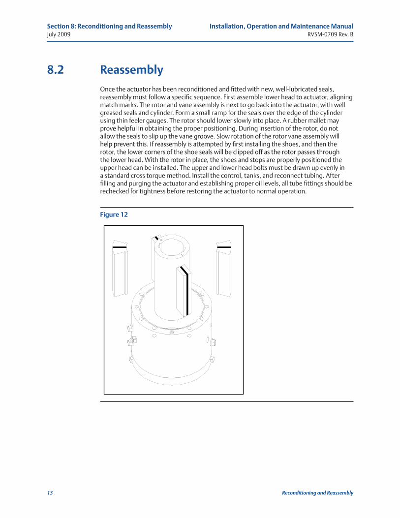
8.2 Reassembly
Once the actuator has been reconditioned and fitted with new, well-lubricated seals, reassembly must follow a specific sequence. First assemble lower head to actuator, aligning match marks. The rotor and vane assembly is next to go back into the actuator, with well greased seals and cylinder. Form a small ramp for the seals over the edge of the cylinder using thin feeler gauges. The rotor should lower slowly into place. A rubber mallet may prove helpful in obtaining the proper positioning. During insertion of the rotor, do not allow the seals to slip up the vane groove. Slow rotation of the rotor vane assembly will help prevent this. If reassembly is attempted by first installing the shoes, and then the rotor, the lower corners of the shoe seals will be clipped off as the rotor passes through the lower head. With the rotor in place, the shoes and stops are properly positioned the upper head can be installed. The upper and lower head bolts must be drawn up evenly in a standard cross torque method. Install the control, tanks, and reconnect tubing. After filling and purging the actuator and establishing proper oil levels, all tube fittings should be rechecked for tightness before restoring the actuator to normal operation.
Figure 12

Installation, Operation and Maintenance ManualRVSM-0709 Rev. B
July 2009
14
Section 9: Troubleshooting
Troubleshooting
Section: 9 Troubleshooting If a particular problem should arise, it is wise to trouble shoot starting with the various components of the system, because most always the actuator itself will be the last source of trouble. In other words , it takes more man-hours to pull the head of an actuator thought to contain bad seals than it does to recondition a component where the problem really exists. The following are the problems that might arise, their causes and what steps to take to correct the situation.
9.1 Problem 1
Spongy, erratic, or faster than normal operations.
• POSSIBLE CAUSE - lack of hydraulic fluid in the actuator.
• SOLUTION - Purge the actuator of all gas and foam and establish proper oil levels as indicated in this manual.
9.2 Problem 2
Actuator moves too slowly.
• POSSIBLE CAUSE - Speed controls, if existent, are pinched too far.
• SOLUTION - Open speed controls to allow more flow.
• POSSIBLE CAUSE - Use of improper hydraulic fluid.
• SOLUTION - Refer to proper oil tables in this manual.
• POSSIBLE CAUSE - Restriction of exhaust port of control.
• SOLUTION - Check to make sure exhaust port is clear and if exhaust is manifolded away that tubing size or length does not restrict or cause back pressure.
• POSSIBLE CAUSE - Restriction of power gas because of:
— Low gas pressure
— Ice in system causing blockage
— Dirt, grease, contaminants in control strainers.
— Power gas connecting lines from pipeline to control too small in diameter.
• SOLUTION - Refer to the Shafer Poppet Block Control Installation, Operation and Maintenance Manual.

July 2009
Installation, Operation and Maintenance Manual RVSM-0709 Rev. B
15
Section 9: Troubleshooting
Troubleshooting
9.3 Problem 3
Actuator wil not turn valve.
• POSSIBLE CAUSE - Low power pressure or valve torque requirements exceed actuator torque output.
• SOLUTION - Turn power gas up, if possible, check torque requirements. Use manual hand pump to create more hydraulic pressure.
• POSSIBLE CAUSE - Actuator and valve are not in same relationship.
• SOLUTION - Check that OPEN actuator is installed on OPEN valve. If not remove position indicator, pull stem key, and hand pump the rotor 90° so that actuator rotor and valve stem are in the same relationship, and reinstall stem key and position indicator.
• POSSIBLE CAUSE - Valve is stuck
• SOLUTION - Lubricate valve and again try to stroke the actuator. If actuator still does not stroke the valve, pull the actuator and hand pump the actuator, if actuator strokes independent of the valve, the valve is most likely the area of trouble.
9.4 Problem 4
Actuator will not stroke when using hand pump.
• POSSIBLE CAUSE - Lack of hydraulic fluid.
• SOLUTION - Purge the actuator of all gas and foam and establish proper operating oil levels in tanks.
• POSSIBLE CAUSE - Malfunction of hand pump.
• SOLUTION - Refer to Shafer Manual Hand Pump Installation, Operation and Maintenance Manual. Run through the three basic check out procedures and if the hand pump is found to be malfunctioning recondition as per manual.
• POSSIBLE CAUSE - Failure of actuator’s seals.
• SOLUTION - After all other factors have eliminated as the cause of trouble, it is necessary to recondition the actuator as per this manual.


For complete list of sales and manufacturing sites, please visit www.emerson.com/actuationtechnologieslocations or contact us at [email protected]
World Area Configuration Centers (WACC) offer sales support, service, inventory and commissioning to our global customers. Choose the WACC or sales office nearest you:
NORTH & SOUTH AMERICA
19200 Northwest FreewayHouston TX 77065USAT +1 281 477 4100F +1 281 477 2809
2500 Park Avenue West Mansfield Ohio 44906USAT +419 529 4311F +419 529 3688
Av. Hollingsworth 325 Iporanga Sorocaba SP 18087-105BrazilT +55 15 3238 3788F +55 15 3228 3300
ASIA PACIFIC
No. 9 Gul Road#01-02 Singapore 629361T +65 6777 8211F +65 6268 0028
No. 1 Lai Yuan RoadWuqing Development AreaTianjin 301700P. R. ChinaT +86 22 8212 3300F +86 22 8212 3308
MIDDLE EAST & AFRICA
P. O. Box 17033DubaiUnited Arab EmiratesT +971 4 811 8100F +971 4 886 5465
P. O. Box 10305Jubail 31961Saudi ArabiaT +966 3 340 8650F +966 3 340 8790
24 Angus CrescentLongmeadow Business Estate East P.O. Box 6908 Greenstone 1616 Modderfontein Extension 5South AfricaT +27 11 451 3700F +27 11 451 3800
EUROPE
Berenyi u. 72- 100 Videoton Industry Park Building #230 Székesfehérvár 8000 HungaryT +36 22 53 0950 F +36 22 54 3700
www.emerson.com/shafer
©2017 Emerson. All rights reserved.
The Emerson logo is a trademark and service mark of Emerson Electric Co. ShaferTM is a mark of one of the Emerson family of companies. All other marks are property of their respective owners.
The contents of this publication are presented for information purposes only, and while every effort has been made to ensure their accuracy, they are not to be construed as warranties or guarantees, express or implied, regarding the products or services described herein or their use or applicability. All sales are governed by our terms and conditions, which are available on request. We reserve the right to modify or improve the designs or specifications of our products at any time without notice.


