15
SHAFT REMOVEL BY PNEUMATIC POWER Submitted by, Eby varghese Prakash john mathew Sachin sundhar Guided by, Mr. GURUMOORTHY ASSISTANT PROFESSOR( MECH)
| Date post: | 26-Oct-2015 |
| Category: |
Documents |
| Upload: | elangandhi |
| View: | 15 times |
| Download: | 0 times |

SHAFT REMOVEL BY PNEUMATIC POWER
Submitted by,Eby varghesePrakash john mathewSachin sundhar
Guided by,Mr. GURUMOORTHY
ASSISTANT PROFESSOR( MECH)

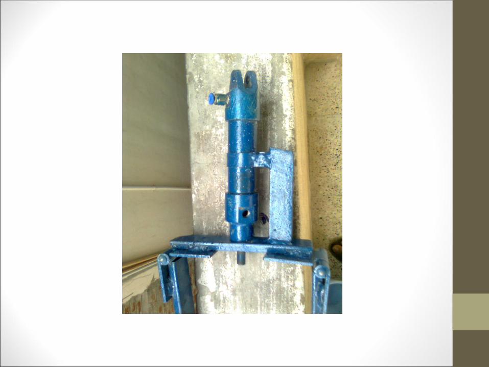
This project namely “SHAFT REMOVER” is designed and fabricated by us is for removing bearings,pulleys and other press fit parts etc
In the early years of industrial revolution,pulling of tools was anything but systematic.However,as more and more sophisticated machinery were developed awhole range of pullers were delivered to the heavy works in the quantities and at speeds appropriate to the situation
Detachable bearing pullers provide an efficient mens for the removel of gears,bearings,wheels,pulleys and other press fit parts.Our project gives the controlled means of applying small manual force without the needs for any hammering or heating process

Common Types Of Remover (PULLER)
*Mechanical*Pneumatic*Hydraulic
GENERAL APPLICATION
AgricultureConstruction
ShipsAviationDeffense
TransportationFabrication
Metal HandlingAutomation

Centrifugal compressorsDiogonal or mixed-flow compressorsAxial-flow compressorsReciprocating compressorsRotary compressorsRotary compressorsScroll compressors
To control pneumatic actuator the air energy has to be regulated controlled and reserved with a pre determined sequence.These are done by pneumatic valve
1.Direction control valve2.Pneumatic valve3.Flow control valve4.pneumatic shuttle valve5.Two pressure valve6.Quick return valve
SELECTION OF PNEUMATICS
SELECTION OF PNEUMATICS
The main advantages of all pneumatic system are usually economy and simplicity, the latter reducing maintenance to a low level. It can also have outstanding advantages in terms of safety .
The single acting pneumatic cylinder consist of the following components to the requirements of complete operation of the machine1.Piston2.Cylinder3.Ram4.End plate5.Return spring6.Nipple

WORKING PRINCIPLE
The compressed air from the compressor is used as the force medium for this operation .There are pneumatic double acting cylinders , solenoid valve; flow control valve and timer unit used. The arm from the compressor enters to the flow control valve. The controlled air from the flow control valve enters to the solenoid valve. The function of solenoid valves all of air correct time interval. The 3/2 solenoid valve is used. In one position air enter to the cylinder and pushes the piston…
The next position air enters to the other side of the cylinder and pushes the piston return back, so that the releasing shock is obtained . With the help of pneumatic ram object can be bend desired shape.

DESIGN ASPECTS
USEDCylinder (M.S Rod)MATERIALS Piston (M.S with Chromium)
Ram (M.S Rod)
Spring (M.S)
Nipple (M.S Rod)


Applications
This machine is very useful for small scale industries
All industrial application
Advantages
The pneumatic is more efficient in the technical field Quick response is achieved Simple in construction Easy to maintain and repair Cost of unit is less when compared to other machine
CONCLUSION
This report deals with the design and fabrication of Pneumatic Bearing press and it’s principle is attached with the line diagrem.the pneumatic system can be found in almost all industries/fields.However some of the industial application is punching,clamping.material handling,hammering throughout the project period we gained knowledge on all type of machining process and pneumatic system is controlled.We have done to our ability and skill making maximum use of available facilities

Thank You


