FINE WOODWORKING 48 he Shaker rocker is one of the most recognized rocking-chair designs, and rightfully so. It has simple and attrac- tive lines, it is economical to build, and, if designed properly, it can be very com- fortable. This chair also is a wonderful project in my woodworking classes because it intro- duces students to spindle turning, steam- bending, and a few important hand-tool techniques. The plans I use in class are an amalgamation of an early brethren’s rocker, which is detailed in John Kassay’s The Book of Shaker Furniture, and the rocking chairs made later at the famous Shaker production shop at Mount Lebanon in New York state. I made a number of modifications to improve the strength of the chair, taking into account modern-day physiques. The original 1 3 ⁄ 8-in.-thick back posts are beefed up to 1 9 ⁄ 16 in. thick, and all of the seat rails and stretchers are about 1 ⁄ 8 in. larger in diameter than those on classic examples of the chair. I also took some historical liberties with its design, incorporating features from vari- ous chairs produced by different Shaker communities. The arms and rockers are 1 ⁄ 2 in. thick and book-matched from the same figured maple board. The front arm posts have a ginger-jar profile and attach to the arms with a through-tenon and a mushroom cap. Finally, the back is woven with one curved back splat above. Turn all of the spindles Turning the various chair parts is fairly straightforward, but there are a few tips and tricks that will make it go easier. To begin, mill all of the stock for the rails, stretchers, and posts to length but just oversize in Shaker Rocker Jigs and story sticks ensure accurate joinery BY ERNIE CONOVER Use a steady rest to turn the long back posts. Conover used a bed extension on his Nova DVR 3000 lathe to accommodate the 43-in.-long posts. At this length, a steady rest is required to pre- vent the turning from chattering when working the center region. TURNING TIPS All of the parts for this chair, except for the arms, rockers, and the curved back slat, are turned on the lathe. The back posts require a steady rest and a lathe that accommodates a 43-in.-long turning. Size the rail tenons precisely with a wrench. Turn the tenons with a wide parting tool until the open-ended wrench slides over the tenon. A simple method to hold the mushroom caps for turning. Turn a tenon on scrap stock, then jam the cap blank over the tenon. Photos: Matt Berger T
Transcript
F I N E W O O D W O R K I N G48
he Shaker rocker is one of the most recognized rocking-chair designs, and rightfully so. It has simple and attrac-
tive lines, it is economical to build, and, if designed properly, it can be very com-fortable.
This chair also is a wonderful project in my woodworking classes because it intro-duces students to spindle turning, steam-bending, and a few important hand-tool techniques. The plans I use in class are an amalgamation of an early brethren’s rocker, which is detailed in John Kassay’s The Book of Shaker Furniture, and the
rocking chairs made later at the famous Shaker production shop at Mount Lebanon in New York state.
I made a number of modifications to improve the strength of the chair, taking into account modern-day physiques. The original 13⁄8-in.-thick back posts are beefed up to 19⁄16 in. thick, and all of the seat rails and stretchers are about 1⁄8 in. larger in diameter than those on classic examples of the chair.
I also took some historical liberties with its design, incorporating features from vari-ous chairs produced by different Shaker
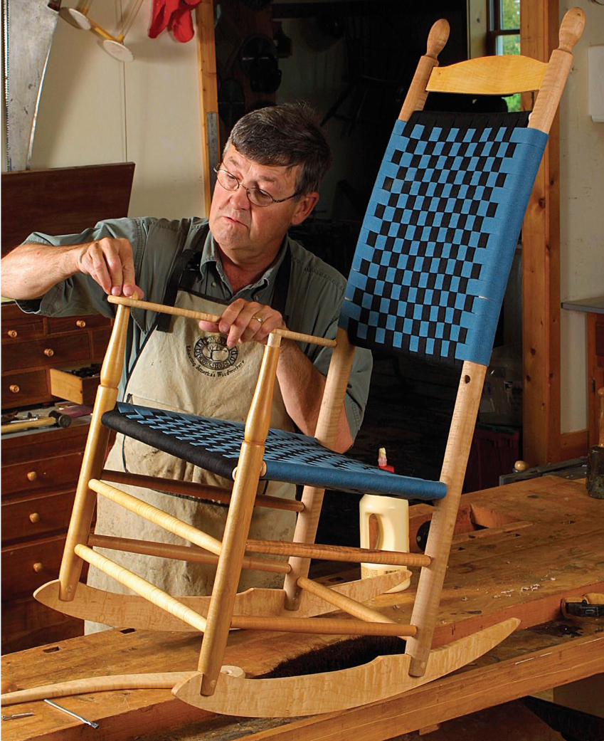
communities. The arms and rockers are 1⁄2 in. thick and book-matched from the same figured maple board. The front arm posts have a ginger-jar profile and attach to the arms with a through-tenon and a mushroom cap. Finally, the back is woven with one curved back splat above.
Turn all of the spindlesTurning the various chair parts is fairly straightforward, but there are a few tips and tricks that will make it go easier. To begin, mill all of the stock for the rails, stretchers, and posts to length but just oversize in
Shaker RockerJigs and story sticks ensure accurate joinery
B Y E R N I E C O N O V E R
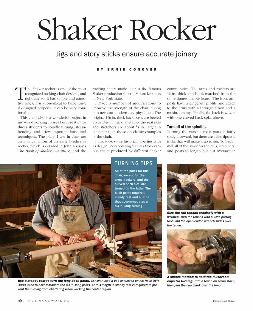
Use a steady rest to turn the long back posts. Conover used a bed extension on his Nova DVR 3000 lathe to accommodate the 43-in.-long posts. At this length, a steady rest is required to pre-vent the turning from chattering when working the center region.
T U R N I N G T I P S All of the parts for this chair, except for the arms, rockers, and the curved back slat, are turned on the lathe. The back posts require a steady rest and a lathe that accommodates a 43-in.-long turning.
Size the rail tenons precisely with a wrench. Turn the tenons with a wide parting tool until the open-ended wrench slides over the tenon.
A simple method to hold the mushroom caps for turning. Turn a tenon on scrap stock, then jam the cap blank over the tenon.
Photos: Matt Berger
T
Credit Here J A N U A R Y / F E B R U A R Y 2 0 0 5 49
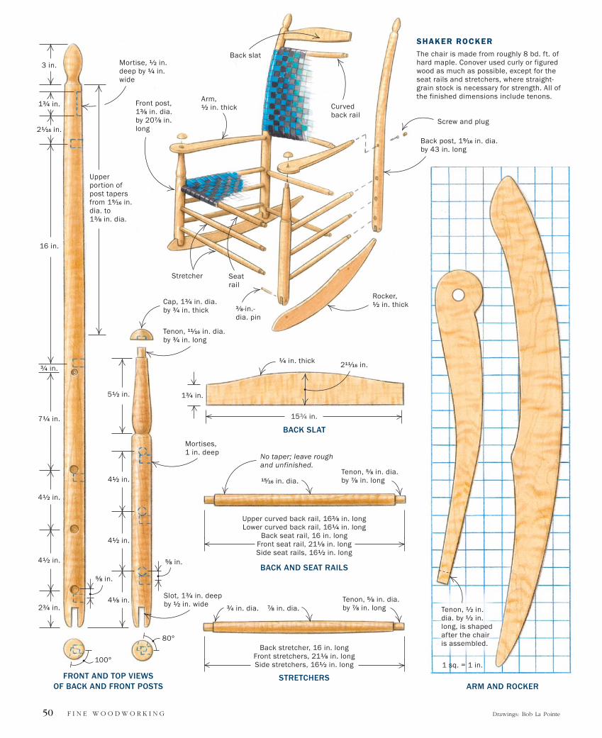
Back stretcher, 16 in. longFront stretchers, 211⁄8 in. longSide stretchers, 161⁄2 in. long
7⁄8 in. dia.Tenon, 5⁄8 in. dia. by 7⁄8 in. long3⁄4 in. dia.
STRETCHERS
Upper curved back rail, 163⁄8 in. longLower curved back rail, 161⁄4 in. long
Back seat rail, 16 in. longFront seat rail, 211⁄8 in. longSide seat rails, 161⁄2 in. long
15⁄16 in. dia.Tenon, 5⁄8 in. dia. by 7⁄8 in. long
BACK AND SEAT RAILS
No taper; leave rough and unfinished.
13⁄4 in.
BACK SLAT
211⁄16 in.1⁄4 in. thick
153⁄4 in.
Tenon, 1⁄2 in. dia. by 1⁄2 in. long, is shaped after the chair is assembled.
F I N E W O O D W O R K I N G50 Drawings: Bob La Pointe
5⁄8 in.
5⁄8 in.
FRONT AND TOP VIEWS OF BACK AND FRONT POSTS
Slot, 13⁄4 in. deep by 1⁄2 in. wide
Tenon, 11⁄16 in. dia. by 3⁄4 in. long
Cap, 13⁄4 in. dia. by 3⁄4 in. thick
Upper portion of post tapers from 19⁄16 in. dia. to 13⁄8 in. dia.
80°
100°
23⁄4 in.
41⁄2 in.
41⁄2 in.
3⁄4 in.
71⁄4 in.
16 in.
13⁄4 in.
21⁄16 in.
3 in.
51⁄2 in.
41⁄8 in.
41⁄2 in.
41⁄2 in.
Back post, 19⁄16 in. dia. by 43 in. long
Seat rail
Curved back rail
Rocker,
1⁄2 in. thick
Arm, 1⁄2 in. thick
Back slat
Front post, 13⁄8 in. dia. by 207⁄8 in. long
Stretcher
SHAKER ROCKER
The chair is made from roughly 8 bd. ft. of hard maple. Conover used curly or figured wood as much as possible, except for the seat rails and stretchers, where straight-grain stock is necessary for strength. All of the finished dimensions include tenons.
ARM AND ROCKER
1 sq. = 1 in.
Mortise, 1⁄2 in. deep by 1⁄4 in. wide
3⁄8-in.-dia. pin
Mortises, 1 in. deep
Screw and plug
thickness so that you have some room for error when turning the delicate stretchers and rails to their final diameters.
This project requires you to be diligent and organized in the way that you mill and dimension the turning billets. Because there are so many parts that are nearly identical, varying only slightly in length and diameter, it’s wise to mark each piece as it’s made.
Steady rest prevents chatter—The long back posts require a lathe with 43 in. be-tween centers. To accommodate that dis-tance, I attached a bed extension to my Nova DVR 3000 lathe. A turning of this length also requires the use of a steady rest, which supports the post at the center to keep it from chattering. Steady rests are available commercially or can be made in the shop (see FWW #161, p. 34 and FWW#143, p. 14, respectively).
Size tenons with a wrench—Another turning trick helps produce consistent and perfectly sized round tenons, which will ensure a good glue bond when they are joined to the round mortises. First, mark the length of the tenon with a set of divid-ers, measuring from the end of the turning. Then, as you approach the final diameter of the tenon, fit an open-ended wrench of the finished diameter over the area. It will slide over the tenon when it’s turned to the correct diameter. Ease into the fit, because if you turn the tenons undersize, you in-crease the chance of the joinery failing.
Finish parts on the lathe—You can sand and finish nearly all of the round parts on the lathe (see FWW #165, pp. 62-65). The exceptions are the back posts, the seat rails, and the curved back rails. The back posts are steam-bent before finishing, and the seat rails and curved back rails are left unfinished to provide traction so the Shak-er-tape weave doesn’t slide around.
The Shakers generally finished their chairs with varnish. I favor either Minwax or Olympic Antique Oil.
Jigs align parts for accurate joineryAfter steam-bending the back posts, you can begin drilling the round mortises for the rail and stretcher joinery. This requires two jigs to hold the posts steady at the drill press. I also make four story sticks to locate the center points of the seat rail
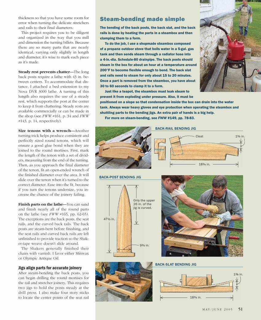
Steam-bending made simpleThe bending of the back posts, the back slat, and the back
rails is done by heating the parts in a steambox and then
clamping them to a form.
To do the job, I use a shopmade steambox composed
of a propane outdoor stove that boils water in a 5-gal. gas
tank and then sends steam through a radiator hose into
a 4-in.-dia. Schedule-80 drainpipe. The back posts should
steam in the box for about an hour at a temperature around
200°F to become flexible enough to bend. The back slat
and rails need to steam for only about 15 to 20 minutes.
Once a part is removed from the steambox, you have about
30 to 60 seconds to clamp it to a form.
Just like a teapot, the steambox must leak steam to
prevent it from exploding under pressure. Also, it must be
positioned on a slope so that condensation inside the box can drain into the water
tank. Always wear heavy gloves and eye protection when operating the steambox and
shuttling parts to the bending jigs. An extra pair of hands is a big help.
For more on steam-bending, see FWW #149, pp. 78-83.
13⁄4 in.
183⁄4 in.
BACK-RAIL BENDING JIG
Cleat
BACK-POST BENDING JIG
471⁄2 in.
Only the upper 26 in. of the jig is curved.
93⁄4 in.
BACK-SLAT BENDING JIG
13⁄8 in.
183⁄4 in.
M AY / J U N E 2 0 0 5 51
F I N E W O O D W O R K I N G52
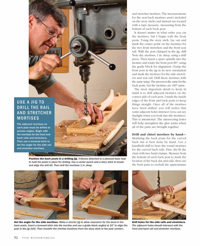
and stretcher mortises. The measurements for the seat-back mortises aren’t included on the story sticks and instead are located with a tape measure, measuring from the bottom of each back post.
It doesn’t matter in what order you cut the mortises, but I begin with the front posts. Using the story stick, lay out and mark the center point on the mortises for the two front stretchers and the front seat rail. With the post clamped in the jig, drill 5⁄8-in.-dia. mortises, 1 in. deep, using a drill press. Then insert a spare spindle into the mortise and rotate the front post 80°, using the guide block for alignment. Clamp the front post in the jig in its new orientation and mark the mortises for the side stretch-ers and seat rail. Drill those mortises with the same setup. The process is the same for the back posts, but the mortises are 100° apart.
The most important detail to keep in mind is to drill adjacent mortises on the correct side of each post. I mark the inside edges of the front and back posts to keep things straight. Once all of the mortises have been drilled, you will notice that some adjacent holes intersect (you can see daylight when you look into the mortises). This is intentional: The intersecting holes will help strengthen the glue joints when all of the parts are brought together.
Drill and chisel mortises by hand—Mortising the back posts for the curved back slat is best done by hand. Use a handheld drill to bore the round mortises for the curved back rails. First, dry-fit the chair with two band clamps. Measure from the bottom of each back post to mark the location of the back slat and rails, then use the bent parts to eyeball the approximate
Position the back posts in a drilling jig. V-blocks attached to a plywood base help to hold the posts in place for drilling. Use a center punch and a story stick to locate and align the drill bit. Then drill the mortises 1 in. deep.
Set the angle for the side mortises. Make a shorter jig to allow clearance for the bend in the back posts. Insert a tenoned stick into the mortise and use a guide block angled at 10° to align the post in the jig (left). Then transfer the mortise locations from the story stick to the post (center).
Drill holes for the side rails and stretchers. The adjacent holes should intersect with the front and back rail and stretcher mortises.
U S E A J I G T O D R I L L T H E R A I L A N D S T R E T C H E R M O R T I S E S The adjacent mortises on each post must be drilled at precise angles. Begin with the mortises for the front and back rails and stretchers. Then use a tenoned stick to set the angle for the side rail and stretcher mortises.
J A N U A R Y / F E B R U A R Y 2 0 0 5 53
angle of each mortise. Hold the chisel to this angle during mortising, and do the same thing with a handheld drill to bore the round mortises for the rails.
Long open time aids assemblyI use 90-minute clear epoxy to assemble the chair, taking advantage of the glue’s long open time and its ability to prevent squeaky joints. Apply well-mixed epoxy to the mortises and tenons with a solder brush. Be sure to wear disposable gloves; epoxy is difficult to get off your skin.
Assemble the back posts first, then add the side stretchers and finish up with the front-post assembly. Two band clamps generally are adequate to hold the chair to-gether while the glue sets. However, dur-ing assembly a bar clamp can be helpful to drive some of the tenons home. Once the chair is clamped, set it on a flat floor and muscle it into proper alignment by stepping on the front rail to hold it steady;
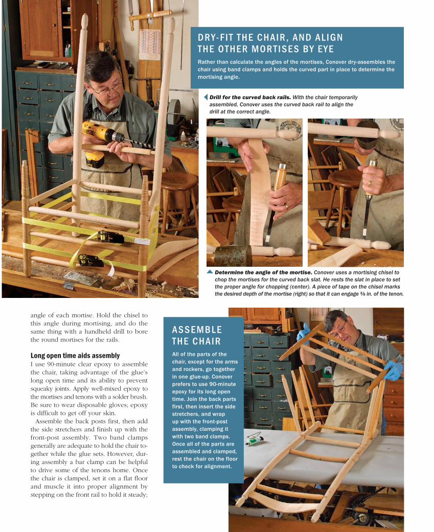
D R Y- F I T T H E C H A I R , A N D A L I G N T H E O T H E R M O R T I S E S B Y E Y ERather than calculate the angles of the mortises, Conover dry-assembles the chair using band clamps and holds the curved part in place to determine the mortising angle.
Drill for the curved back rails. With the chair temporarily assembled, Conover uses the curved back rail to align the drill at the correct angle.
Determine the angle of the mortise. Conover uses a mortising chisel to chop the mortises for the curved back slat. He rests the slat in place to set the proper angle for chopping (center). A piece of tape on the chisel marks the desired depth of the mortise (right) so that it can engage 3⁄8 in. of the tenon.
A S S E M B L E T H E C H A I RAll of the parts of the chair, except for the arms and rockers, go together in one glue-up. Conover prefers to use 90-minute epoxy for its long open time. Join the back parts first, then insert the side stretchers, and wrap up with the front-post assembly, clamping it with two band clamps. Once all of the parts are assembled and clamped, rest the chair on the floor to check for alignment.
F I N E W O O D W O R K I N G54
then shake the back posts side to side and front to back.
Attach rockers after glue-upI choose highly figured material for the arms and rockers. The arms are book-matched and the rockers mirror-matched, so only one of each needs to be shaped. Trace the pat-terns onto planed 5/4 material, bandsaw to the lines, and handplane or sand away all saw and planer marks. Resaw the shaped pieces, then plane them to 1⁄2 in. thick. Finally, round over the top and bottom edges of the arms with a 1⁄4-in. roundover bit.
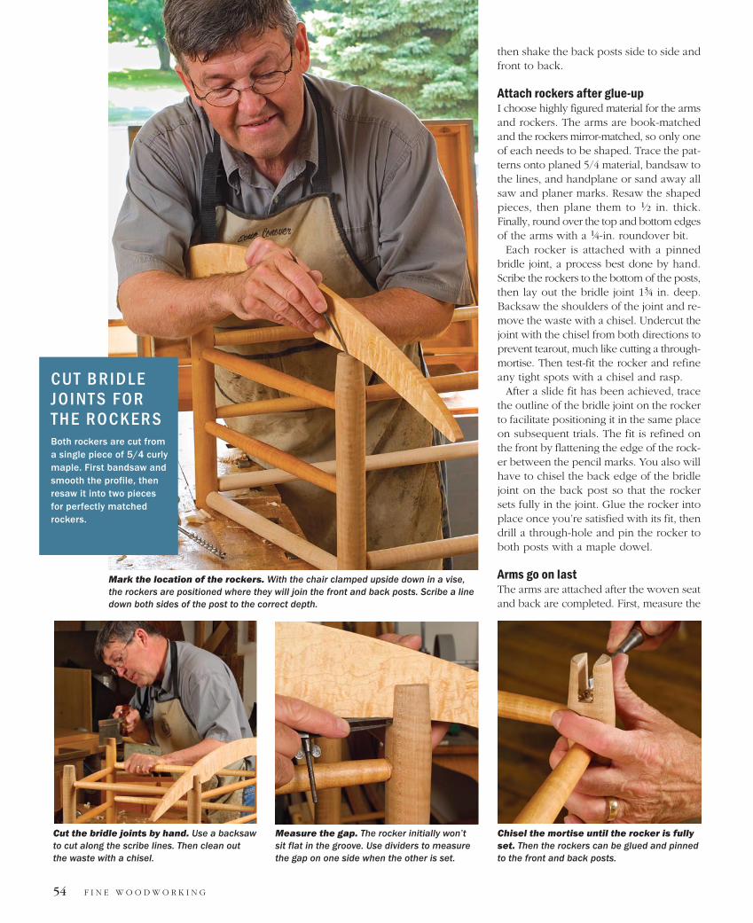
Each rocker is attached with a pinned bridle joint, a process best done by hand. Scribe the rockers to the bottom of the posts, then lay out the bridle joint 13⁄4 in. deep. Backsaw the shoulders of the joint and re-move the waste with a chisel. Undercut the joint with the chisel from both directions to prevent tearout, much like cutting a through-mortise. Then test-fit the rocker and refine any tight spots with a chisel and rasp.
After a slide fit has been achieved, trace the outline of the bridle joint on the rocker to facilitate positioning it in the same place on subsequent trials. The fit is refined on the front by flattening the edge of the rock-er between the pencil marks. You also will have to chisel the back edge of the bridle joint on the back post so that the rocker sets fully in the joint. Glue the rocker into place once you’re satisfied with its fit, then drill a through-hole and pin the rocker to both posts with a maple dowel.
Arms go on lastThe arms are attached after the woven seat and back are completed. First, measure the
Mark the location of the rockers. With the chair clamped upside down in a vise, the rockers are positioned where they will join the front and back posts. Scribe a line down both sides of the post to the correct depth.
Cut the bridle joints by hand. Use a backsaw to cut along the scribe lines. Then clean out the waste with a chisel.
Measure the gap. The rocker initially won’t sit flat in the groove. Use dividers to measure the gap on one side when the other is set.
Chisel the mortise until the rocker is fully set. Then the rockers can be glued and pinned to the front and back posts.
C U T B R I D L E J O I N T S F O R T H E R O C K E R SBoth rockers are cut from a single piece of 5/4 curly maple. First bandsaw and smooth the profile, then resaw it into two pieces for perfectly matched rockers.
55
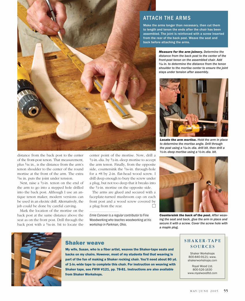
distance from the back post to the center of the front-post tenon. That measurement, plus 1⁄16 in., is the distance from the arm’s tenon shoulder to the center of the round mortise at the front of the arm. The extra 1⁄16 in. puts the joint under tension.
Next, raise a 1⁄2-in. tenon on the end of the arm to go into a stepped hole drilled into the back post. Although I use an an-tique tenon maker, modern versions can be used in an electric drill. Alternatively, the job could be done by careful carving.
Mark the location of the mortise on the back post at the same distance above the seat as on the front post. Drill through the back post with a 1⁄16-in. bit to locate the
Shaker weaveMy wife, Susan, who is a fiber artist, weaves the Shaker-tape seats and
backs on my chairs. However, most of my students find that weaving is
part of the fun of making a Shaker rocking chair. You’ll need about 80 yd.
of 1-in.-wide tape to complete this chair. For instruction on weaving with
Shaker tape, see FWW #121, pp. 78-81. Instructions are also available
from Shaker Workshops.
center point of the mortise. Now, drill a 1⁄2-in.-dia. by 1⁄2-in.-deep mortise to accept the arm tenon. Finally, from the opposite side, countersink the 1⁄16-in. through-hole for a #8 by 2-in. flat-head wood screw. I drill deep enough to bury the screw under a plug, but not too deep that it breaks into the 1⁄2-in. mortise on the opposite side.
The arms are glued and secured with a faceplate-turned mushroom cap on each front post and a wood screw covered by a plug from the rear.
Ernie Conover is a regular contributor to Fine Woodworking who teaches woodworking at his workshop in Parkman, Ohio.
AT TAC H T H E A R M SMake the arms longer than necessary, then cut them to length and tenon the ends after the chair has been assembled. The joint is reinforced with a screw inserted from the rear of the back post. Weave the seat and back before attaching the arms.
Measure for the arm joinery. Determine the distance from the back post to the center of the front-post tenon on the assembled chair. Add 1⁄16 in. to determine the distance from the tenon shoulder to the mortise center to ensure the joint stays under tension after assembly.
Countersink the back of the post. After weav-ing the seat and back, glue the arm in place and secure it with a screw. Cover the screw hole with a maple plug.
Locate the arm mortise. Hold the arm in place to determine the mortise angle. Drill through the post using a 1⁄16-in.-dia. drill bit, then drill a 1⁄2-in.-deep mortise using a 1⁄2-in.-dia. bit.