SHAPE MEMORY ALLOY ROBOTIC TRUSS Except where reference is made to the work of others, the work described in this thesis is my own or was done in collaboration with my advisory committee. This thesis does not include proprietary or classified information. _________________________________ Lori Michelle Prothero Certificate of Approval: ________________________________ ________________________________ Winfred A. Foster, Jr. Robert S. Gross, Chair Professor Associate Professor Aerospace Engineering Aerospace Engineering ________________________________ ________________________________ David A. Cicci George T. Flowers Professor Dean Aerospace Engineering Graduate School
Transcript
SHAPE MEMORY ALLOY ROBOTIC TRUSS
Except where reference is made to the work of others, the work described in this thesis is my own or was done in collaboration with my advisory committee.
This thesis does not include proprietary or classified information.
_________________________________ Lori Michelle Prothero
Certificate of Approval: ________________________________ ________________________________ Winfred A. Foster, Jr. Robert S. Gross, Chair Professor Associate Professor Aerospace Engineering Aerospace Engineering
________________________________ ________________________________ David A. Cicci George T. Flowers Professor Dean Aerospace Engineering Graduate School
SHAPE MEMORY ALLOY ROBOTIC TRUSS
Lori Michelle Prothero
A Thesis
Submitted to the
Graduate Faculty of
Auburn University
in Partial Fulfillment of the
Requirements for the
Degree of
Master of Science
Auburn, Alabama August 9, 2008
iii
SHAPE MEMORY ALLOY ROBOTIC TRUSS
Lori Michelle Prothero
Permission is granted to Auburn University to make copies of this thesis at its discretion, upon request of individuals or institutions and at their expense.
The author reserves all publications rights.
________________________________ Signature of Author
________________________________ Date of Graduation
iv
VITA
Lori Michelle Prothero, daughter of Karen R. S. Prothero and granddaughter of
the late Myrtle R. Setzer and the late Robert L. Setzer, was born November 4, 1981, in
Jacksonville, Florida. She graduated as Valedictorian of Watauga High School in
Boone, North Carolina, in June 2000. In May of 2004, Prothero graduated Cum
Laude and as a University Honors Scholar with a Bachelor of Aerospace Engineering
degree from Auburn University in Auburn, Alabama. During her first year at Auburn,
Prothero began working in the Adaptive Aerostructures Laboratory for Dr. Ronald
Barrett. In her third year of enrollment, she received the Auburn University
Undergraduate Competitive Research Fellowship to independently research and
develop a space structure utilizing adaptive materials. In April of 2004, Prothero
presented her research findings at the National Conference of Undergraduate Research
in Indianapolis, Indiana. In December of 2003 she was accepted to be a Master's
candidate at Auburn University starting in the fall of 2004 to continue her work with
adaptive structures. In the spring of 2006, Prothero's second generation prototype
space truss using adaptive materials was tested in reduced gravity by the Auburn
University NASA Reduced Gravity Student Team (Proposal ID: 2006-1767) in
Houston, Texas aboard the NASA C-9 aircraft.
v
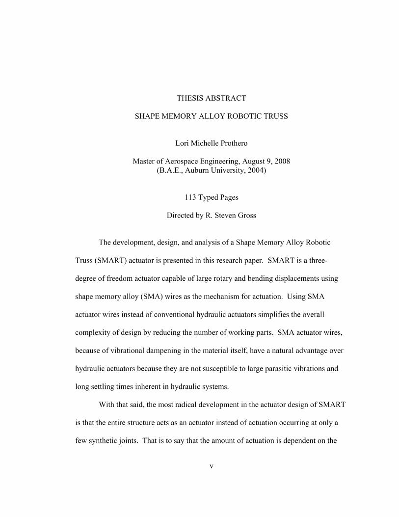
THESIS ABSTRACT
SHAPE MEMORY ALLOY ROBOTIC TRUSS
Lori Michelle Prothero
Master of Aerospace Engineering, August 9, 2008 (B.A.E., Auburn University, 2004)
113 Typed Pages
Directed by R. Steven Gross
The development, design, and analysis of a Shape Memory Alloy Robotic
Truss (SMART) actuator is presented in this research paper. SMART is a three-
degree of freedom actuator capable of large rotary and bending displacements using
shape memory alloy (SMA) wires as the mechanism for actuation. Using SMA
actuator wires instead of conventional hydraulic actuators simplifies the overall
complexity of design by reducing the number of working parts. SMA actuator wires,
because of vibrational dampening in the material itself, have a natural advantage over
hydraulic actuators because they are not susceptible to large parasitic vibrations and
long settling times inherent in hydraulic systems.
With that said, the most radical development in the actuator design of SMART
is that the entire structure acts as an actuator instead of actuation occurring at only a
few synthetic joints. That is to say that the amount of actuation is dependent on the
vi
length of SMART and corresponds directly to the structural stiffness of the truss. For
this reason, the truss backbone of the SMART actuator was designed to be structurally
weak in torsion, strong in tension, and weak in axial bending to allow for the twisting
and bending actuations. The actuation force is provided by the contraction of SMA
wires which are attached in a specific pattern, to be described in further detail later, to
wire guides at nodes along the truss. The force of the SMA wire’s contraction is
distributed to the truss through the nodes at which the SMA is attached. That is to say
that the nodes connected to the SMA wire become closer, and as a result, the SMA’s
contraction actuates the entire truss.
The ability of the SMAs to contract is a unique material property of their
crystalline structure to be trained at high heat to remember a desired length. When
cold, SMAs can be mechanically stretched easily; however, they immediately return to
the remembered length when a heat stimulus is applied. Exploiting this material
property, electricity was supplied to one or multiple SMA wires in a simple circuit in
which the SMA wires acted as the resistors. The resistance produced heat in the SMA
wires which then contracted in approximately a second to their remembered length.
The result is that the entire truss actuated in a specified mode depending on which
wires were heated.
Results of SMART from ground based testing and reduced gravity testing
aboard the NASA C-9 aircraft, while undergoing parabolic trajectories to simulate
reduced gravity, demonstrated the feasibility of SMART as an actuator truss capable
of large actuations and functionality in a reduced gravity environment such as space.
vii
ACKNOWLEDGEMENTS
The author would like to thank Dr. Ronald Barrett for being the primary
faculty mentor throughout the research, for his expertise in shape memory alloy
research, and for his awesome support of the project. The author would also like to
thank Dr. R. Steven Gross for assuming the position of major professor when Dr.
Barrett accepted a position at the University of Kansas. Special thanks are due Dr.
Gross for his knowledge, support, and motivation throughout the writing process and
without whom this thesis would not have been possible. The author would like to
thank the Auburn University Undergraduate Competitive Research Fellowship which
helped fund this research. The author wish to acknowledge the Auburn University
NASA Reduced Gravity Student Flight Opportunities Project (RGSFOP) Team who
flew with the research prototypes aboard the NASA C-9 research aircraft in March of
2006. The author also wishes to thank the Lord to whom all praise is due for the
ability to think and discover the awesome world He has created.
viii
Style manual or journal used: American Institute of Aeronautics and Astronautics
Journal
Computer software used: Microsoft Word 2003, Microsoft Excel 2003
ix
TABLE OF CONTENTS
LIST OF SYMBOLS ........................................................................................... xii
LIST OF TABLES ............................................................................................. xiv
LIST OF FIGURES ............................................................................................. xv
I. INTRODUCTION ............................................................................................. 1
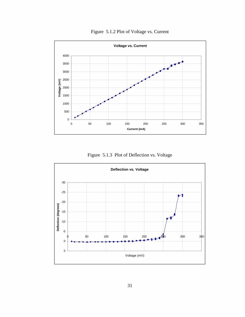
II. SHAPE MEMORY ALLOY ........................................................................... 5
Figure 2.1.4 Diagram of Crystalline Transformations as SMA Heats and Cools, δ Denotes Elongation ................................. 8
Figure 2.2.1 Phase Change Graph as a Function of Temperature ........................ 9
Figure 2.3.1 Diagram of Shape Memory Alloy Changing Physical Shape and Phases ............................................................. 10
Figure 2.4.2 Simple Test of SMA Material Characteristics ............................... 13
Figure 2.4.3 Sample Test Data from Material Test of a 0.01” Diameter SMA Wire ....................................................................... 14
Figure 11.8.1 Base Assembly Before Ready for Tensioning Screws ................. 57
Figure 11.8.2 Finished Base Assembly with Tensioning Screws ...................... 58
Figure 11.10.1 SMA Wires on the Twisting Model of the SMART .................. 60
Figure 12.1.1 Ground Based Test Setup of Bending Truss ................................ 62
Figure 13.1.1 Photograph of SMART at Maximum Bending Deflection With and Without Displacement Measurements on Image .......... 65
Figure 13.1.2 Side-by-Side Comparisons of Bending SMART Pretest, Posttest, and Posttest with Residual Bend Measurement ............. 66
Figure 13.2.1 Photograph of Twisting Truss At Maximum Deflection Posttest ........................................................................ 67
Figure 13.2.2 Plot of Twisting of SMART per Segment ................................... 67
Figure B.1 Photograph of Test Setup Showing Laser, Test Stand, and DC Power Supply ................................................... 75
Figure B.2 Enhanced photograph of the SMA Truss on the Test Stand ............ 75
Figure B.3 Close-up Photograph of the Torsional Strain Relief Device ............ 76
Figure B.4 Photograph of Test Setup with Test Stand, Laser, and Wall Graph Board ............................................................................. 76
Figure C.1. Frame of Maximum Twist Extracted from Video of Twist in Clockwise Direction ...................................................... 78
Figure C.2 Frame of Truss Post Clockwise Twist with Relaxed SMA Extracted from Video of Twist in Clockwise Direction ................... 78
Figure C.3. Frame of Truss at Beginning of Counterclockwise Test Video ...... 79
Figure C.4. Frame Extracted Near Maximum Restoring Counterclockwise Twist from Test Video ..................................................................... 79
Figure D.1. Final Iteration of Twisting Smart Posttest with Measurements of Twist ................................................................... 81
xviii
Figure D.2 Close-up Photograph of Twisting SMART with Color Coding ....... 82
Figure D.3 Researcher Lori Prothero with the Posttest SMART ....................... 82
Figure E.1. Auburn University “Vomit Comet” Team at Team Readiness Review .................................................................. 85
Figure E.2. Ream Readiness Review Presentation with SMART Test Module at Right ......................................................... 85
Figure E.3. Demonstration of SMART Operations Inside Plexiglas Enclosure with NASA C-9 Aircraft in Background ........................ 86
Figure E.4. Unpacking and Presentation of Twisting SMART at Team Readiness Review .................................................................. 86
Figure E.5. Team Preflight Physiological Testing in Altitude Simulator .......... 87
Figure E.6. Andrew Wright during Physiological Test ...................................... 87
Figure E.7. Flight Crew and Flyers from March 9, 2006 at Johnson Space Center in Houston, Texas flight aboard the NASA C-9 Reduced Gravity Aircraft ............................ 88
Figure E.8. Ryan SMART Flyers Leureck and Vanessa Smith from March 9, 2006 Flight .............................................................. 88
Figure E.9. Andrew Wright, Backup Flyer for SMART Received Opportunity to Fly with Experiment from Another University on March 9, 2006 ........................................................... 89
Figure E.10. Ryan Leureck During Reduced Gravity Flight .............................. 89
Figure E.11. Andrew Wright During Reduced Gravity Flight ........................... 90
Figure E.12. Ryan Leureck and Vanessa Smith Operating SMART During Reduced Gravity Parabola .................................. 90
Figure E.13. Vanessa Smith and Ryan Leureck Observing SMART During Reduced Gravity Parabola .................................. 91
Figure E.14. Vanessa Smith and Ryan Leureck Observing SMART Through Top of Plexiglass Enclosure ............................. 91
xix
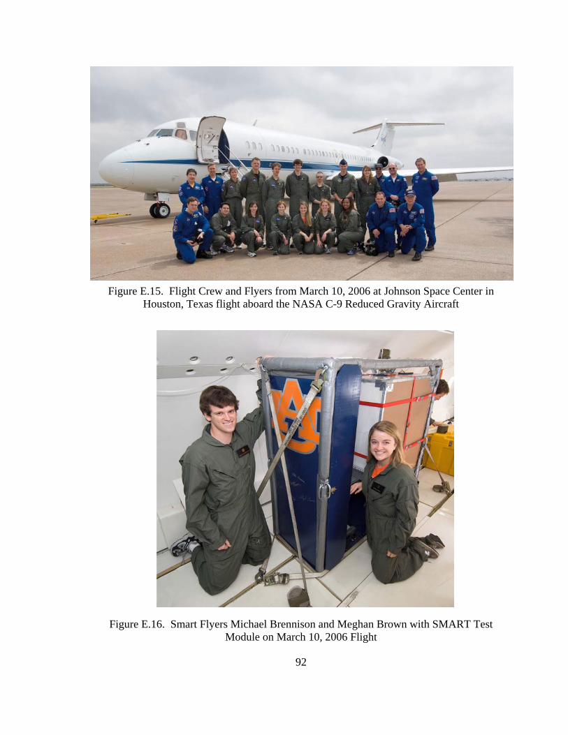
Figure E.15. Flight Crew and Flyers from March 10, 2006 at Johnson Space Center in Houston, Texas flight aboard the NASA C-9 Reduced Gravity Aircraft .......................... 92
Figure E.16. Smart Flyers Michael Brennison and Meghan Brown with SMART Test Module on March 10, 2006 Flight ................... 92
Figure E.17. Smart Flyers Michael Brennison and Meghan Brown During Reduced Gravity Flight on March 10, 2006 ....................... 93
Figure E.18. Meghan Brown During Reduced Gravity ...................................... 93
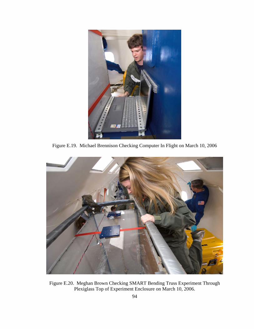
Figure E.19. Michael Brennison Checking Computer In Flight ........................ 94
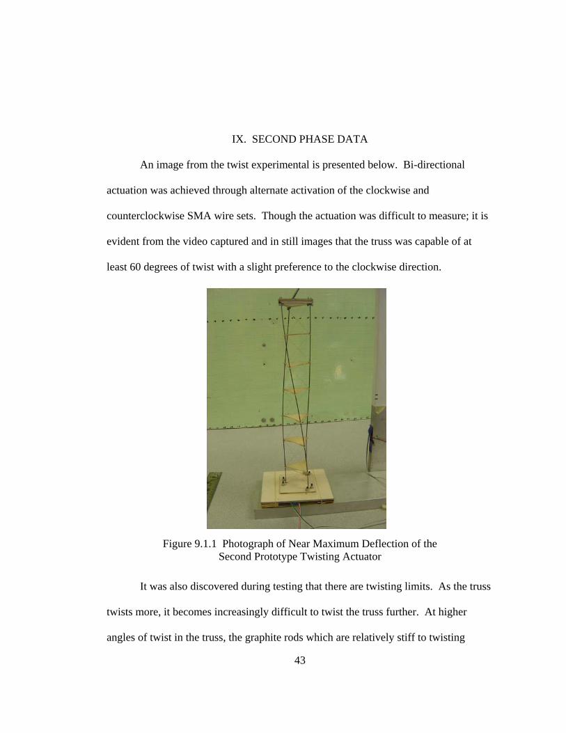
were inadequately stiff locally to prevent buckling. This required a redesign of the
triangles during testing to add a more a rigid plywood web. Redesign of the SMA
carrier triangles was noted as an opportunity for improvement in future prototyping.
During testing, it was shown that increasing the voltage and current above minimum
operational activation would increase the speed of the actuation; however, it would
probably lead to shorter fatigue life. Also, an important observation was made that the
more truss module segments in the truss, the more twist actuation is capable because
the amount of twist contributed by each truss cell is additive. Because there was
discovered a limitation on the amount of twist which can be achieved in this design, a
redesign of the support structure was recommended as essential to achieve better
twisting capabilities.
46
XI. THIRD DESIGN PHASE
The third design iteration marked a complete metamorphosis of the design with
the resulting third iteration resembling the earlier designs very little; however, the
essential technology behind the twisting actuation had changed very little. The third
design phase also added bending actuation capability to the twisting truss.
11.1 REDESIGN OF SMART CARRIER STRUCTURE
New consideration was give to the earlier Padget design which had utilized a
central graphite rod as a spine with equally spaced KEVLAR® squares with integrated
wire guides at the corners and cross members through the center to make a hole
through which the spine was placed and secured with cyanoacryllate. The third
iteration of SMART utilized Padget’s heritage application for a bending actuator with
SMA at four corners. Applying the lessons learned from the previous two SMART
iterations that KEVLAR® are not sufficiently stiff in compression for more than the
smallest scales, the wire guide structure was completely redesigned in a different
material. Prepreg fiberglass fabric was chosen as the new material for the SMA wire
carriers because of its increased compressive strength as well as for being an electrical
insulator.
Instead of using a graphite spine along which the square SMA carriers were
permanently affixed with cyanoacryllate, a steel rod of approximately 0.60 inches was
used. Further design influences came from nature and from snake vertebrae which
have a great deal of articulation due to the allowed rotation of their vertebrae in the
spinal column. Therefore, the fiberglass SMA carriers were allowed to rotate freely
about the central steel spine and were only constrained from translating along the
spine by the addition of collets on either side of the fiberglass vertebrae. When the
first prototype fiberglass vertebrae was produced, it was discovered that it did not slide
well about the steel spine because of the “brooming” delaminations which form as
holes are drilled; therefore steel washers just larger than the diameter of the steel spine
were added as inclusions in the layup to serve as crude bearings. There were no
observed delaminations around the modified vertebrae with steel washers for bosses as
is evident in the photograph of a finished vertebra. The steel washer bosses also
served as alignments for the templates to be affixed to the cured blanks.
Figure 11.1.1 Pattern for Fiberglass Vertebrae, left and Photograph of Finished Vertebra, right
Further design alterations were made to accommodate six holes for SMA wires
in each node instead of the original five. It was thought that by tying the SMA wires
to each vertebra that the force would be better transferred to the vertebra instead of
relying on contact with the rough drilled hole edge. Also, this method was developed
47
48
to maximize the pull force of each unit of the spine and allow each vertebra to work
equally. This concept was quickly abandoned when it was discovered that the wires
degraded rapidly from tying in such tight knots and the heating in the wires was not
uniform. The wires located at the ends were doing the most pulling. Rather than
remake the vertebrae for only three holes at each corner (one for bending wire,
clockwise twist, and counterclockwise twist), the vertebrae were used as is with
leaving three of the holes empty. The pull force of the wire was allowed to
equivalence itself along the entire length of the spine, and it was discovered that
bearing directly on the rough hole guides did not affect the wires significantly. It
should be noted as a risk that frequent chafing from the holes could cause premature
wear on the SMA wires. The inclusion of some sort of silicone inserts or grommets
would alleviate this chafing.
11.2 DETAILED CONSTRUCTION INFORMATION
Two SMARTs were made almost identically except that one was wired for
bending and the other for twisting. Both bending and twisting model SMARTs use
the same base components as follows:
A. Central Spine B. Fiberglass Vertebrae C. Collets D. End Cap Assembly E. Anchor Screws F. Base Assembly G. Tensioning Screws H. Shape Memory Alloy (SMA) Wires I. Electrical wiring
11.3 CENTRAL SPINE
The central spine is a steel rod with a diameter between 0.058 and 0.065
inches. One end of the steel rod is inserted into the base assembly and secured with
cyanoacryalate. See Section on Base Assembly. The other end of the rod is sharpened
to a point and mates with the End Cap. Refer to section on End Cap Assembly. See
photograph below.
Figure 11.3.1 Cap End of Central Spine
11.4 FIBERGLASS VERTEBRAE
“Clover-shaped” Fiberglass Vertebrae are located every three inches along the
Central Spine and simply supported by collets on either side. The individual vertebrae
are made from four plies of epoxy pre-impregnated fiberglass with a washer placed
middle layer to reinforce the central hole in the finished vertebrae. The blank lay-up is
placed between two caul plates and heated in an autoclave for two hours at 177°C.
Patterns are placed on the blank to align with the washers. Then the pattern is cut out
using a band saw, and the holes are drilled with a hand drill. The holes accommodate
49
the Shape Memory Alloy wires and act as electrical insulators between the Central
Spine and each SMA wire at the nodes. The Vertebrae slides onto the steel spine and
is secured between two Collets which prevent the vertebrae from translating. See
section 11.5 on collets.
Figure 11.4.1 Integrated Vertebrae on Central Spine
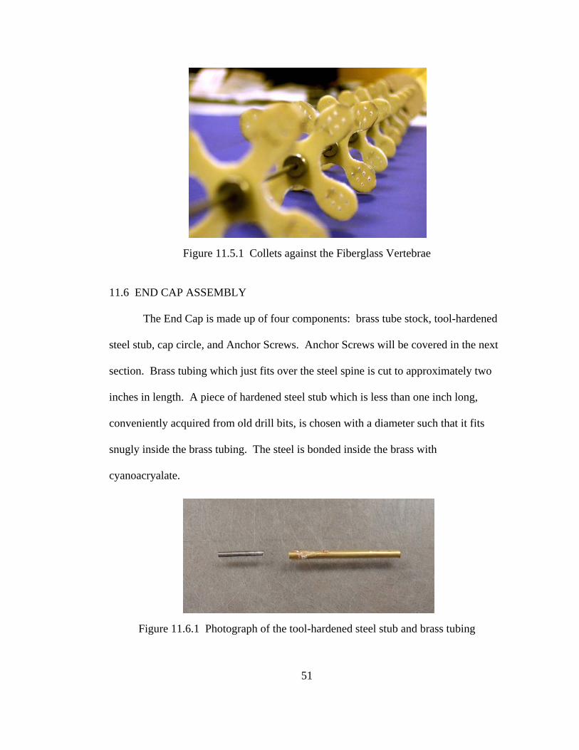
11.5 COLLETS
The Collets are appropriately sized to fit over the steel Central Spine and
contain set screws which tighten them onto the steel spine. The set screws will either
require a jeweler’s screwdriver or appropriate sized hex key/Allen key. Collets may
be purchased at a hobby supply store. Each Fiberglass Vertebrae is sandwiched
between two collets to prevent translation up or down the Central Spine. Please note
that the Collets do not prevent rotation.
50
Figure 11.5.1 Collets against the Fiberglass Vertebrae
11.6 END CAP ASSEMBLY
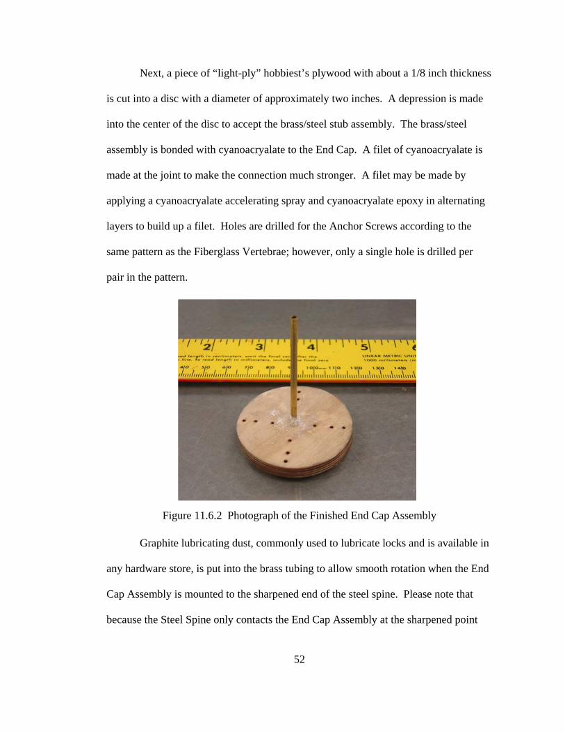
The End Cap is made up of four components: brass tube stock, tool-hardened
steel stub, cap circle, and Anchor Screws. Anchor Screws will be covered in the next
section. Brass tubing which just fits over the steel spine is cut to approximately two
inches in length. A piece of hardened steel stub which is less than one inch long,
conveniently acquired from old drill bits, is chosen with a diameter such that it fits
snugly inside the brass tubing. The steel is bonded inside the brass with
cyanoacryalate.
Figure 11.6.1 Photograph of the tool-hardened steel stub and brass tubing
51
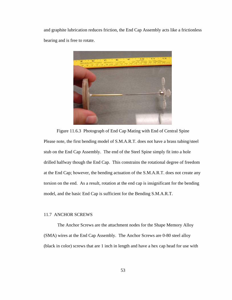
Next, a piece of “light-ply” hobbiest’s plywood with about a 1/8 inch thickness
is cut into a disc with a diameter of approximately two inches. A depression is made
into the center of the disc to accept the brass/steel stub assembly. The brass/steel
assembly is bonded with cyanoacryalate to the End Cap. A filet of cyanoacryalate is
made at the joint to make the connection much stronger. A filet may be made by
applying a cyanoacryalate accelerating spray and cyanoacryalate epoxy in alternating
layers to build up a filet. Holes are drilled for the Anchor Screws according to the
same pattern as the Fiberglass Vertebrae; however, only a single hole is drilled per
pair in the pattern.
Figure 11.6.2 Photograph of the Finished End Cap Assembly
Graphite lubricating dust, commonly used to lubricate locks and is available in
any hardware store, is put into the brass tubing to allow smooth rotation when the End
Cap Assembly is mounted to the sharpened end of the steel spine. Please note that
because the Steel Spine only contacts the End Cap Assembly at the sharpened point
52
and graphite lubrication reduces friction, the End Cap Assembly acts like a frictionless
bearing and is free to rotate.
Figure 11.6.3 Photograph of End Cap Mating with End of Central Spine
Please note, the first bending model of S.M.A.R.T. does not have a brass tubing/steel
stub on the End Cap Assembly. The end of the Steel Spine simply fit into a hole
drilled halfway though the End Cap. This constrains the rotational degree of freedom
at the End Cap; however, the bending actuation of the S.M.A.R.T. does not create any
torsion on the end. As a result, rotation at the end cap is insignificant for the bending
model, and the basic End Cap is sufficient for the Bending S.M.A.R.T.
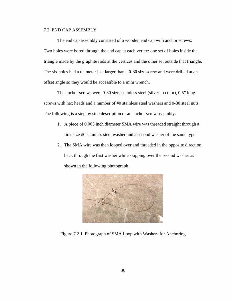
11.7 ANCHOR SCREWS
The Anchor Screws are the attachment nodes for the Shape Memory Alloy
(SMA) wires at the End Cap Assembly. The Anchor Screws are 0-80 steel alloy
(black in color) screws that are 1 inch in length and have a hex cap head for use with
53
an Allen key. The following instructions are the step by step description for installing
the Anchor Screws:
1. Take one 0-80 steel alloy (black in color) screw that is 1 inch in length.
2. Thread one 0-80 stainless nut until it is snug against the cap head of the screw.
(The original Bender model omitted this step)
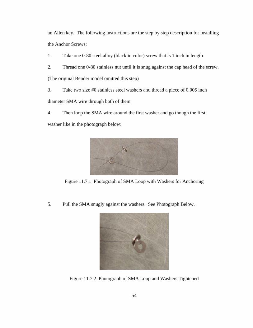
3. Take two size #0 stainless steel washers and thread a piece of 0.005 inch
diameter SMA wire through both of them.
4. Then loop the SMA wire around the first washer and go though the first
washer like in the photograph below:
Figure 11.7.1 Photograph of SMA Loop with Washers for Anchoring
5. Pull the SMA snugly against the washers. See Photograph Below.
Figure 11.7.2 Photograph of SMA Loop and Washers Tightened
54
6. Put the 0-80 alloy screw with washer through the washer such that the head of
the screw ends up on the same side as the SMA wire ends. See Figure 10.
7. Push washers up the screw until snug against the nut. See Photograph Below.
Figure 11.7.3 Anchor Screw with SMA Assembly Attached
8. Thread another 0-80 stainless nut on the screw until snug against the washers
so that the washers are sandwiched between nuts.
9. Thread another 0-80 stainless nut on the screw and stop before reaching the
other nuts/washers leaving approximately a 1/8 inch gap for Bending model
S.M.A.R.T., a 1/8 inch gap for Twisting model S.M.A.R.T. outside wires, or a ¼ inch
gap for the Twisting model S.M.A.R.T. inner wires.
10. Add a size #0 stainless steel washer against the last nut on the screw.
11. Put screw assembly into hole on End Cap and push tight against cap.
12. Add a size #0 stainless steel washer against the outside facing side of the End
Cap.
13. Add a 0-80 stainless nut until it is snug against washer and End Cap.
55
Figure 11.7.4 Completed Anchor Screw Assembly
14. Check to see that the SMA wire is firmly attached to the screw assembly and
that the screw assembly is firmly attached to the End Cap.
15. For electrical contacts, it may be desirable to add another 0-80 nut to the screw
with a 1/8 inch gap. Then add an electrical lead, as pictured above, and secure with
another nut. This step may be modified accordingly or omitted as in the case of
alligator type electrical connectors.
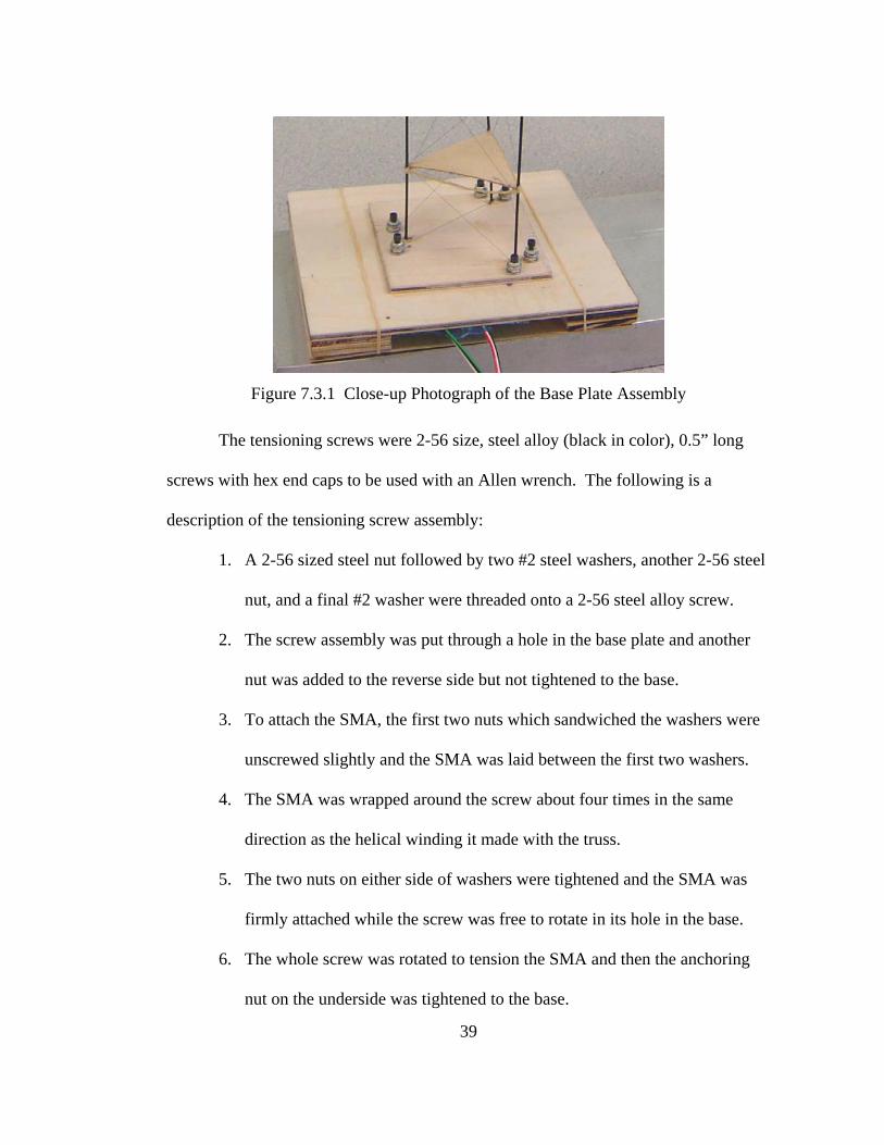
11.8 BASE ASSEMBLY
The Base Assembly consists of a base block which is about 4 inches long with
embedded 2-56 plated nuts for 2-56 steel alloy (black in color) Tension Screws and a
Mounting Base Plate. The end of the Central Spine attaches to the Base Assembly in a
hole drilled into the top of the block. The joint is secured using cyanoacryalate in the
hole and a filet of cyanoacryalate around the outside of the joint. The filet is made
56
similarly to the filet around the End Cap. A hole is drilled into the base block which is
the diameter of the 2-56 screws at a depth of approximately ¼ inch. Then a punch is
used to make a depression in the wood centered on the screw hole. The nut is placed
in the depression and then pounded into the wood until it is flush with the surface of
the base block. Cyanoacryalate is applied around the edge of the nut to assure the nut
is firmly attached. The process is repeated on each of the four sides of the base as
shown in the following picture.
Figure 11.8.1 Base Assembly Before Ready for Tensioning Screws
57
Figure 11.8.2 Finished Base Assembly with Tensioning Screws
11.9 TENSIONING SCREWS
The Tensioning Screws work similar to tuning pegs on a guitar which enable
tightening and loosening of wires using a mechanical screw. The Tensioning Screws
are made from 2-56 steel alloy (black in color) 1 inch screws.
On the Bending Model, as pictured above in Figure 13, two nuts are screwed
together onto the screw with only a slight gap between them. The screw assembly is
then turned partially into one of the nuts mounted in the Base Assembly (See
Photograph Above). The SMA wire is wound in the gap in a clockwise motion so that
as the screw is tightened into the Base Assembly, the wire gets tighter. As the screw is
loosened, the wire becomes loose. The SMA must wrap around the screw several
58
59
times and the nuts must be tightened together for the SMA wire to be secured
by friction.
The Twisting Model works similarly to the Bending Model with the addition
of two washers between the nuts which give more surface area to clamp onto the
SMA wire.
Tension should be relatively close in each of the wires and may be felt by
touching the wires. The wires should not have any slack but should not be so tight
that the S.M.A.R.T. is almost rigid.
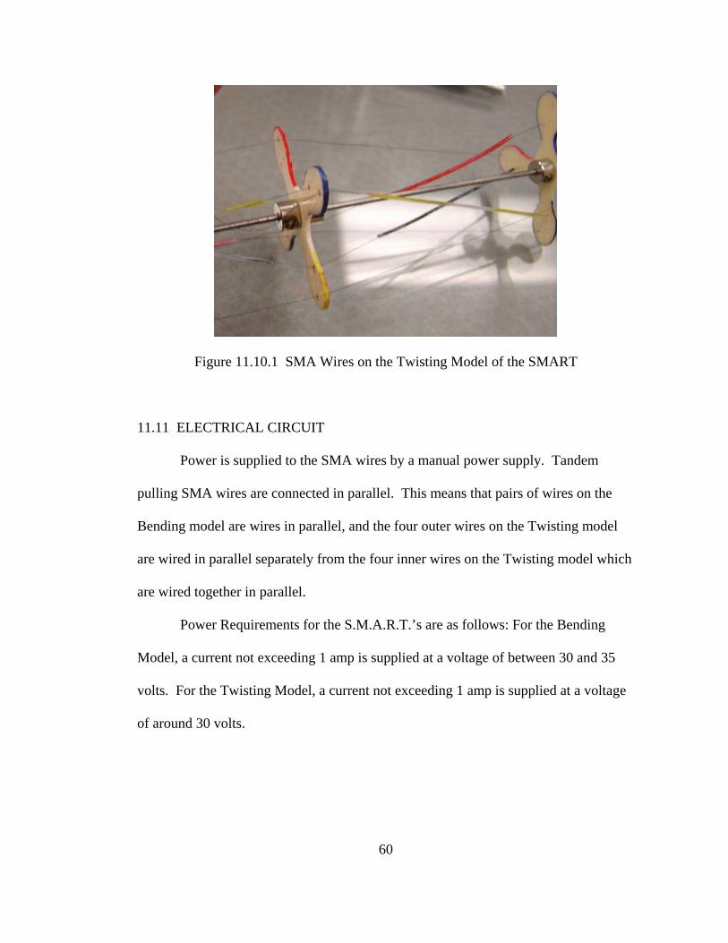
11.10 SHAPE MEMORY ALLOY (SMA) WIRES
Nickel Titanium Shape Memory Alloy Wires with a transition temperature of
70°C and a diameter of 0.005 inches are used. Wires should be cut to approximately
42 inches to insure overrun. Please refer to directions about Anchor screws and
Tensioning Screws for instructions on how to connect the wires.
On the Bending Model, wires run linearly from one node to the next in the
same corresponding hole. On the Twisting Model, sets of wires run clockwise and
counterclockwise as in Figure 11.10.1. The inner set of wires use Teflon tubing
inserted over the wires in the stringing process. The tubing is approximately 2/3 of
the length of the exposed wire length nodes.
60
Figure 11.10.1 SMA Wires on the Twisting Model of the SMART
11.11 ELECTRICAL CIRCUIT
Power is supplied to the SMA wires by a manual power supply. Tandem
pulling SMA wires are connected in parallel. This means that pairs of wires on the
Bending model are wires in parallel, and the four outer wires on the Twisting model
are wired in parallel separately from the four inner wires on the Twisting model which
are wired together in parallel.
Power Requirements for the S.M.A.R.T.’s are as follows: For the Bending
Model, a current not exceeding 1 amp is supplied at a voltage of between 30 and 35
volts. For the Twisting Model, a current not exceeding 1 amp is supplied at a voltage
of around 30 volts.
61
XII. GROUND AND REDUCED GRAVITY FINAL TESTING
The ground based tests of both the twisting and bending were conducted using
nearly identical setups as the previous iterations of SMART. The actuation modes
were tested separately on identical SMARTs with one wired with helical SMA for
twisting and the other wired linearly for bending. This was done to accommodate the
need for redundant test articles for two days of testing aboard the NASA C-9 aircraft.
If one SMART failed, the other would be ready to go that day and be available for
reworking to accommodate the other mode testing during the night between flights. A
third truss structure was made; however, it was not wired and was there in case spare
parts were needed or could be wired in case both trusses failed or the flown truss could
not be reworked.
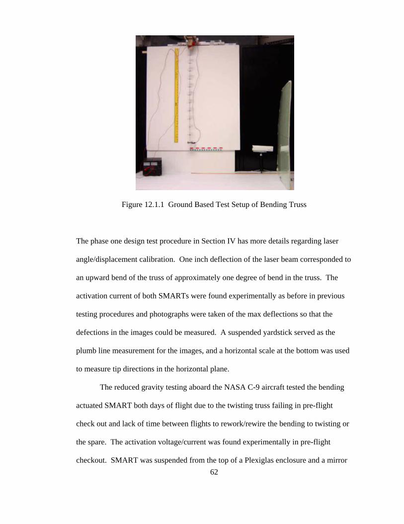
In ground based testing, SMART was suspended by its base which was
clamped in a fixture. A graph board was placed just behind SMART so that
displacements could be measured from still and video images taken of the truss.
Additionally, a mirror was mounted to the tip of the truss and a laser beam bounced
off of the mirror onto a graph board to measure deflections of the tip of SMART more
accurately.
Figure 12.1.1 Ground Based Test Setup of Bending Truss
The phase one design test procedure in Section IV has more details regarding laser
angle/displacement calibration. One inch deflection of the laser beam corresponded to
an upward bend of the truss of approximately one degree of bend in the truss. The
activation current of both SMARTs were found experimentally as before in previous
testing procedures and photographs were taken of the max deflections so that the
defections in the images could be measured. A suspended yardstick served as the
plumb line measurement for the images, and a horizontal scale at the bottom was used
to measure tip directions in the horizontal plane.
The reduced gravity testing aboard the NASA C-9 aircraft tested the bending
actuated SMART both days of flight due to the twisting truss failing in pre-flight
check out and lack of time between flights to rework/rewire the bending to twisting or
the spare. The activation voltage/current was found experimentally in pre-flight
checkout. SMART was suspended from the top of a Plexiglas enclosure and a mirror 62
63
was mounted on the tip of SMART to reflect the laser beam onto a graph board.
Smart was manually turned on just before the 30 seconds of parabolic path freefall for
approximately 60 cycles of parabolas per flight. Digital video equipment continuously
captured movements of the reflected laser point as SMART actuated and stored the
video to the hard drive of a laptop in the test enclosure. The enclosure was mounted
on four large dampers so that vibrations from the C-9 aircraft would have less effect
on the data. The detailed circuit, test setup, photographs from the flights, as well as
the operations manual for SMART for the reduced gravity testing by the Auburn
University NASA Reduced Gravity Student Team is available in the Appendix.
64
XIII. GROUND AND REDUCED GRAVITY TEST DATA
The two SMARTs were tested in ground based tests. Both SMARTs were
slated to fly aboard the NASA C-9 aircraft in reduced gravity; however, due to
technical difficulty, the Twisting SMART was scratched and the Bending SMART
was flown on both days of flight on March 9-10, 2006 at NASA Johnson in Houston,
Texas. The members of the Auburn University team who performed the in flight
operations of SMART were Michael Brennison, Ryan Leureck, Megan Brown, and
Vanessa Smith, Andrew Wright and Christopher Worley served as ground crew and
backup crew for flight operations.
13.1 BENDING SMART GROUND TEST
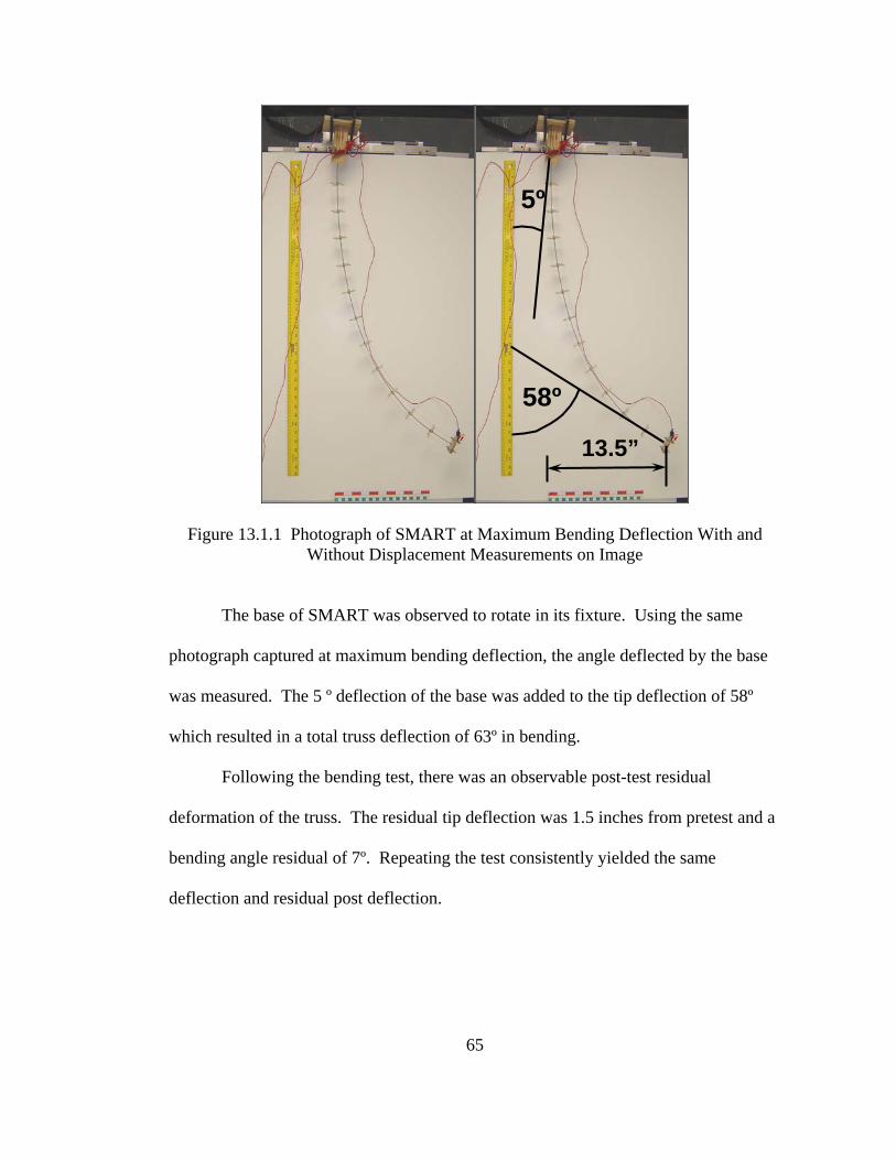
In testing the bending truss, the laser beam left the graph board before max
deflection. Also, because of the high deflection of the tip of SMART, the laser beam
no longer focused on the mirror. The still image of bending SMART at maximum
actuation shows a tip deflection of 13.5 inches in the horizontal and a tangent angle of
the tip section of 58 degrees from the vertical yellow yardstick. Measurements were
calculated from image processing of the photograph taken at maximum deflection
from a camera mounted perpendicular to test plane.
5º
13.5”
58º
Figure 13.1.1 Photograph of SMART at Maximum Bending Deflection With and Without Displacement Measurements on Image
The base of SMART was observed to rotate in its fixture. Using the same
photograph captured at maximum bending deflection, the angle deflected by the base
was measured. The 5 º deflection of the base was added to the tip deflection of 58º
which resulted in a total truss deflection of 63º in bending.
Following the bending test, there was an observable post-test residual
deformation of the truss. The residual tip deflection was 1.5 inches from pretest and a
bending angle residual of 7º. Repeating the test consistently yielded the same
deflection and residual post deflection.
65
7º
Figure 13.1.2 Side-by-Side Comparisons of Bending SMART Pretest, Posttest, and Posttest with Residual Bend Measurement
13.2 TWISTING SMART GROUND TEST
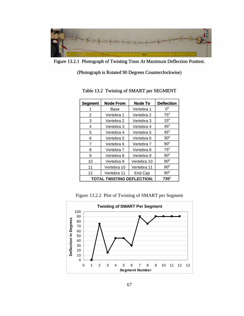
The ground based testing of the twisting truss used a mirror mounted on the tip
of the truss in the same setup as the bending test. No appreciable measurements were
captured from the laser point as the point only reflected the local twisting of the end
cap. Local twisting occurred all along the length of the truss, and as a result, the total
deflection of the entire structure was calculated from the measured twisting of each
segment visible at maximum actuation of SMART.
66
Figure 13.2.1 Photograph of Twisting Truss At Maximum Deflection Posttest.
(Photograph is Rotated 90 Degrees Counterclockwise)
Figure 13.2.1 Photograph of Twisting Truss At Maximum Deflection Posttest.
(Photograph is Rotated 90 Degrees Counterclockwise)
Table 13.2 Twisting of SMART per SEGMENT Table 13.2 Twisting of SMART per SEGMENT
Figure 13.2.2 Plot of Twisting of SMART per Segment
Twisting of SMART Per Segment
0102030405060708090
100
0 1 2 3 4 5 6 7 8 9 10 11 12 13Segment Number
Def
lect
ion
in D
egre
es
67
68
13.3 BENDING SMART REDUCED GRAVITY TEST
The Bending SMART flew aboard the NASA C-9 Aircraft and operated safely.
Post flight analysis of the structure certified that the structure remained intact for the
entire flight and still maintained mechanical functionality following reduced gravity
operations. Observations from the flight test crew indicated that SMART worked as
anticipated and experienced bending deflections of more than 90 degrees during
reduced gravity sets. The video captured in-flight did not have an adequate frame of
reference to measure true deflection of SMART from normal. What can de derived
from the film is that there was a gain of approximately 12 degrees in the max
deflection during the reduced gravity sets when compared to the max deflection in
normal gravity. This was measured from the deflection of the laser beam on a
graphboard between max deflection at constant gravity and max deflection at reduced
gravity.
69
XIV. SMART PROGRAM CONCLUSIONS
There were many strides as well as many lessons learned over the course of
SMART development, and the final SMART design benefits from both. SMART
successfully satisfied the fit, form, and function of a degree of deflection bending and
twisting actuator. Ground based testing produced approximately 70 degrees bending
and a little over 2 full rotations of the structural components. Further reduced gravity
testing of SMART in bending resulted in additional bending by conservative estimates
of more than 10 degrees. Successful flight tests aboard the NASA C-9 aircraft
certified SMART as a reduced gravity actuator and raised the design’s technology
readiness level one step closer to space operations and the transition from prototype to
production.
Further design refinements to be considered in the future are: to find a better
method of electrical insulation for SMA wires that will not hinder even heating of the
wires, work out actuation control to achieve intermediate actuation, integrating
operations of bending and twisting in tandem on a single SMART, creating a
mathematical model to further explore the additive effects of segment actuation of a
chain of segments, and studying out-gassing of materials in SMART and considering
using materials which would be more suitable in a vacuum and under very hot and
very cold temperatures.
70
REFERENCES
1. Fromer, J., Sectionally Heated Shape Memory Alloy Actuator for Multiple Position Aircraft Roll Control, M.S. Thesis, Auburn University, Auburn, Alabama, 2002. 2. Srinivasan, A. V., and McFarland, D. M., Smart Structures: Analysis and Design, Cambridge University Press, Cambridge, United Kingdom, 2001, pp. 26-72 3. Schwartz, M., Encyclopedia of Smart Materials, John Wiley & Sons, Inc., New York, New York, Vol.2, 2002, p. 923. 4. Barrett, R. M., Introduction to Adaptive Aerostructures, Short Course Presented at Auburn University, May 2003. 5. Howard, N. A. Design, Construction, and Analysis of a 2-Degree-Of-Freedom Shape Memory Alloy Rotary Actuator, M.S. Thesis, Auburn University, Auburn, Alabama, 2000.
6. Padgett, D. A. The Design and Construction of a Shape Memory Alloy Tail Boom Actuator. 41st Aerospace Sciences Meeting and Exhibit. 6-9 January 2003, Reno, Nevada 7. Otsuka, K. and Wayman, C. Shape Memory Materials, Cambridge University Press, Cambridge, United Kingdom, 1999. 8. Banks, H., Smith, R., and Wang, Y., Smart Material Structures: Modeling, Estimation, and Control, John Wiley & Sons, Inc., New York, New York, 1996, pp. 18-26. 9. Dynalloy Co. Web Page, http://www.sma-inc.com/Actuator.html, 2004. 10. Kelly, A., Concise Encyclopedia of Composite Materials, MIT Press, Cambridge, Massachusetts, 1989, pp 33-35. 11. Hibbler, R., Mechanics of Materials, Prentice Hall, Upper Saddle River, New Jersey, 2000, p. 92.
71
APPENDIX A
PROPERTIES OF SHAPE MEMORY ALLOYS
72
Table A.1 NiTiNOL Flexinol ® Published Technical Data5
Transformation Temperature -100 to 200 °C Latent Heat of Transformation 40 cal/g atom Shape Memory Strain 8.4% Maximum
74
APPENDIX B
PHOTOGRAPHS OF TEST SETUP
FOR FIRST DESIGN ITERATION
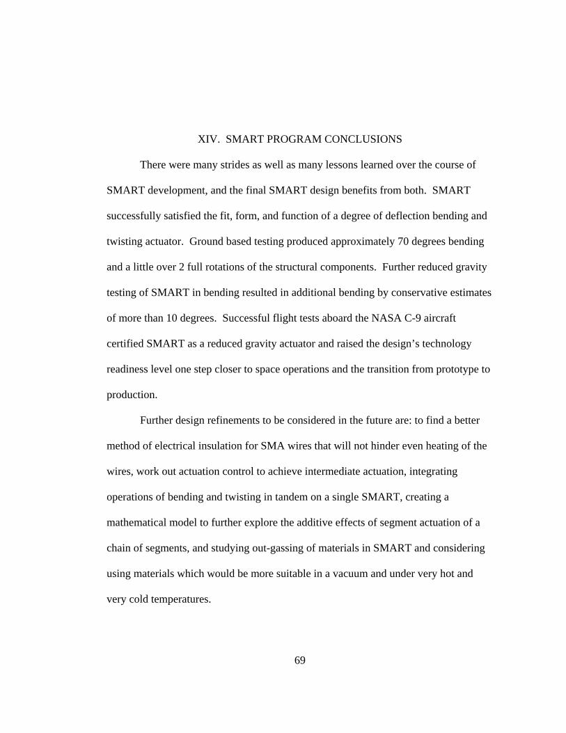
Figure B.1 Photograph of Test Setup Showing Laser, Test Stand, and DC Power Supply
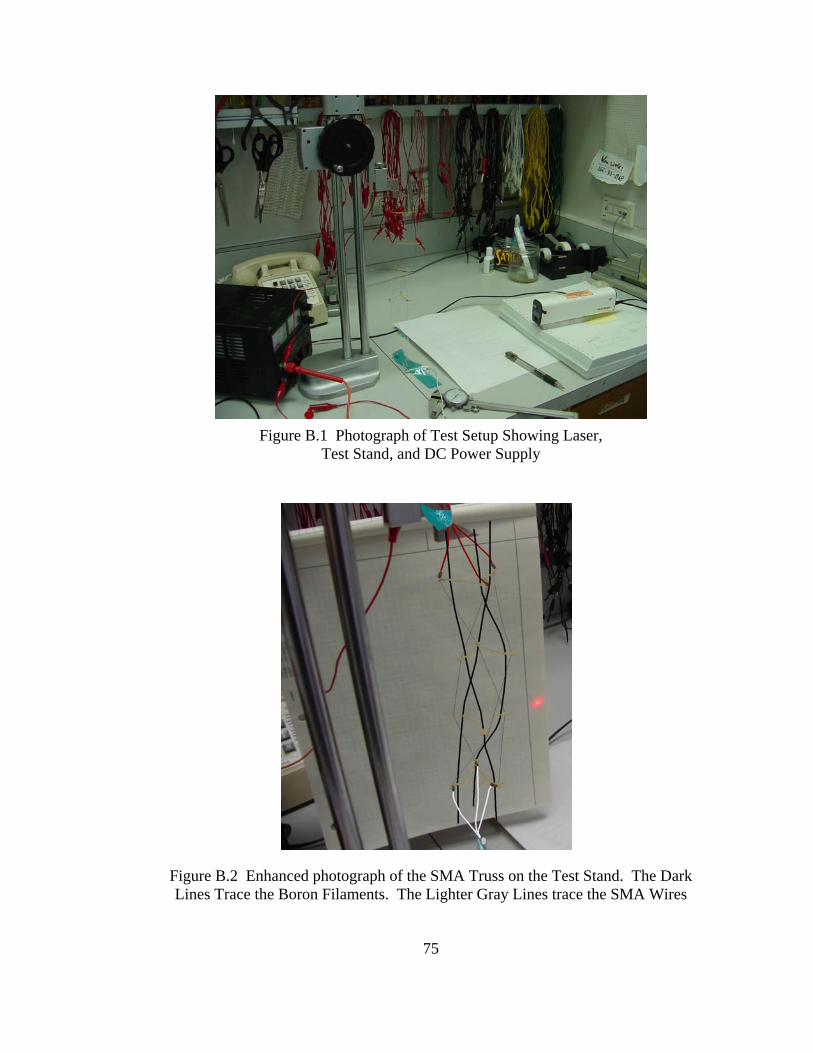
Figure B.2 Enhanced photograph of the SMA Truss on the Test Stand. The Dark Lines Trace the Boron Filaments. The Lighter Gray Lines trace the SMA Wires
75
76
Figure B.3 Close-up Photograph of the Torsional Strain Relief Device Which is the White Coil in the Photograph
Figure B.4 Photograph of Test Setup with Test Stand, Laser, and Wall Graph Board
77
APPENDIX C
PHOTOGRAPHS FROM SECOND DESIGN ITERATION
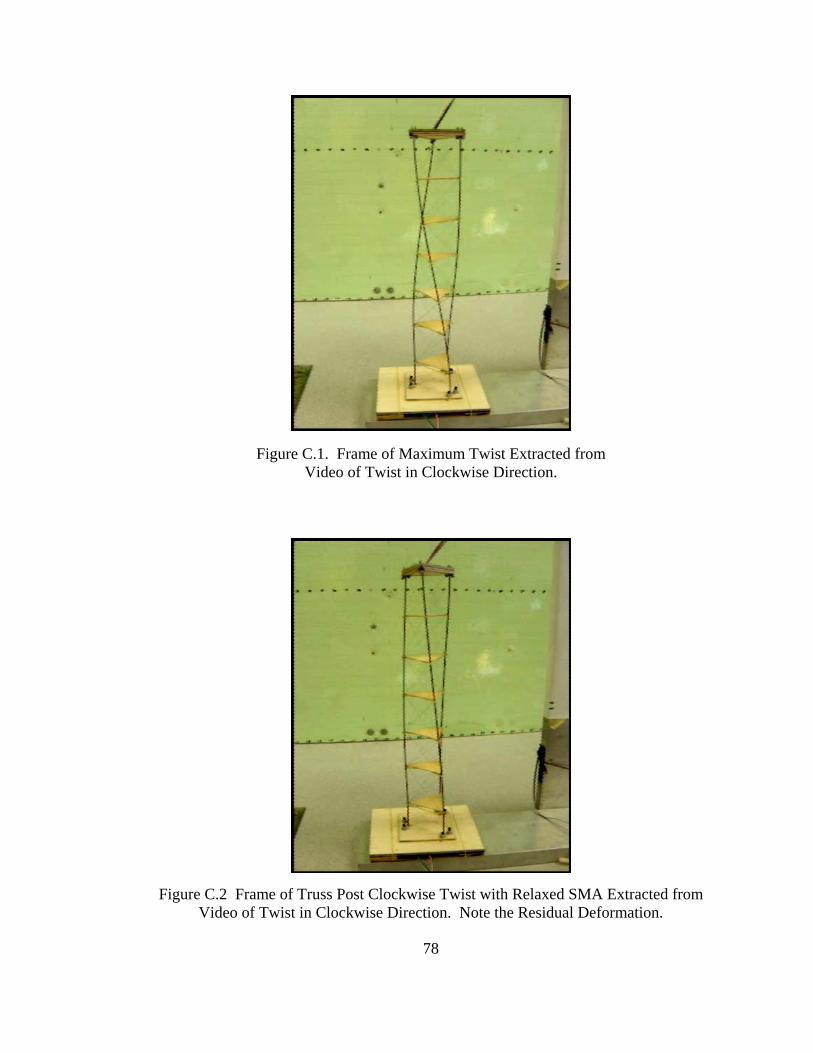
Figure C.1. Frame of Maximum Twist Extracted from Video of Twist in Clockwise Direction.
Figure C.2 Frame of Truss Post Clockwise Twist with Relaxed SMA Extracted from
Video of Twist in Clockwise Direction. Note the Residual Deformation.
78
79
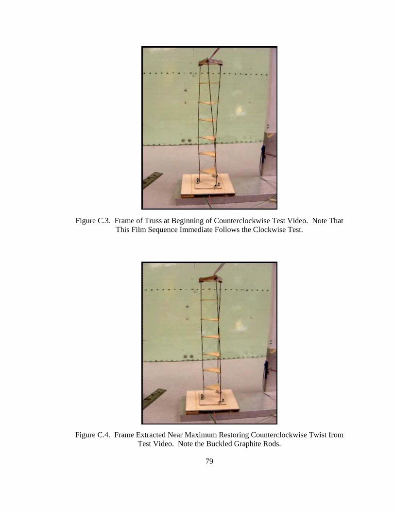
Figure C.3. Frame of Truss at Beginning of Counterclockwise Test Video. Note That
This Film Sequence Immediate Follows the Clockwise Test. Figure C.4. Frame Extracted Near Maximum Restoring Counterclockwise Twist from
Test Video. Note the Buckled Graphite Rods.
80
APPENDIX D
PHOTOGRAPHS OF POSTTEST
OF FINAL SMART TWISTING TRUSS
0 degrees
75 degrees
15 degrees
45 degrees
90 degrees
90 degrees
90 degrees
45 degrees
75 degrees
90 degrees
90 degrees
30 degrees
0 degrees
75 degrees
15 degrees
45 degrees
90 degrees
90 degrees
90 degrees
45 degrees
75 degrees
90 degrees
90 degrees
30 degrees
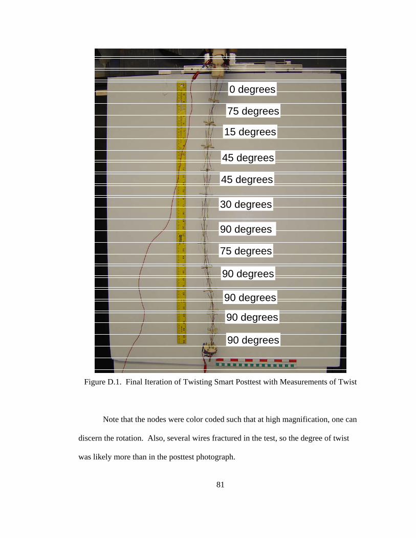
Figure D.1. Final Iteration of Twisting Smart Posttest with Measurements of Twist
Note that the nodes were color coded such that at high magnification, one can
discern the rotation. Also, several wires fractured in the test, so the degree of twist
was likely more than in the posttest photograph.
81
82
Figure D.2 Close-up Photograph of Twisting SMART with Color Coding Evident
Figure D.3 Researcher Lori Prothero with the Posttest SMART
83
APPENDIX E
REDUCED GRAVITY TESTING OF SMART IN BENDING
84
SMART Reduced Gravity Testing Proposal Abstract Reprinted from Microgravity University
Auburn University 2006 Shape Memory Alloy Robotic Truss Shape Memory Alloys (SMA) belong to a special class of metals with a unique crystalline structure that can be heat trained to remember a specific size or shape, which it will return to when a heat stimulus is applied. Because of the ability to stretch and shrink repeatedly with strain recovery, SMA are the ideal materials for mechanical devices that perform repetitive tasks, or actuators. An actuator, as the name implies, is a mechanical device which causes something else to move.4 Actuators can be composed of a large number of moving parts such as gears and hydraulic pistons. The light-weight and simplicity of shape memory alloys have made them a great alternative to conventional actuator systems. SMA have the capacity to reduce the complexity of an actuator by replacing many moving parts with a few strands of SMA wire. This reduces spacecraft actuator mass, which can be significant to reducing launch costs. Replacing hydraulic pistons and gears with a single wire also reduces the vibrational settling time, or shaking, as the actuator moves, causing hydraulically mechanized machines to be imprecise in their movements.4 As a result, vibration is a major limiting factor in robotic design, especially in a space environment because it has fewer media to help dampen the undesired movement. Two proof-of-concept designs previously completed by team members show the feasibility of SMA actuation, both linearly and torsionally. The overall goal of Team SMART is to build and test two fully functional SMA actuated Remote Manipulator Systems (RMS’s) designed to function in a reduced gravity environment. The team will then compare mechanical characteristics including fatigue life, nodal deflections, total deflections, force, stress, and coiling phenomena between gravitational field and reduced gravity environments. The testing will increase the technological readiness level for SMA spaceflight actuated devices and will help to develop a correlation factor for linear actuation and coiling phenomena.
Figure E.1. Auburn University “Vomit Comet” Team at Team Readiness Review Team Members (Left to Right): Meghan Brown, Chris Worley, Unknown Girl Not on
Team, Vanessa Smith, Andrew Wright, Ryan Lureck, Michael Brennison
85
Figure E.2. Team Readiness Review Presentation with SMART Test Module at Right
Figure E.3. Demonstration of SMART Operations Inside Plexiglas Enclosure with NASA C-9 Aircraft in Background
Figure E.4. Unpacking and Presentation of Twisting SMART at Team Readiness Review
86
87
Figure E.5. Team Preflight Physiological Testing in Altitude Simulator
Figure E.6. Andrew Wright during Physiological Test
Figure E.7. Flight Crew and Flyers from March 9, 2006 at Johnson Space Center in Houston, Texas flight aboard the NASA C-9 Reduced Gravity Aircraft
Figure E.8. Ryan SMART Flyers Leureck and Vanessa Smith from March 9, 2006 Flight
88
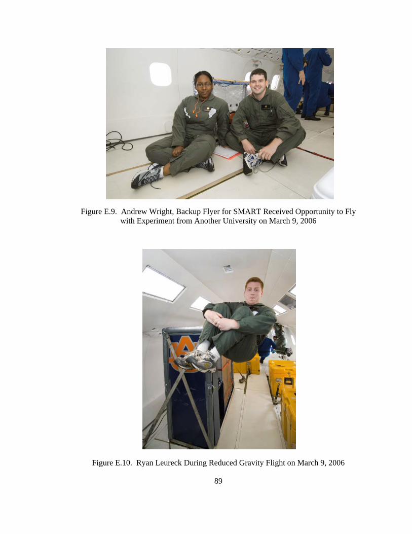
Figure E.9. Andrew Wright, Backup Flyer for SMART Received Opportunity to Fly with Experiment from Another University on March 9, 2006
89
Figure E.10. Ryan Leureck During Reduced Gravity Flight on March 9, 2006
Figure E.11. Andrew Wright During Reduced Gravity Flight on March 9, 2006
Figure E.12. Ryan Leureck and Vanessa Smith Operating SMART During Reduced Gravity Parabola on March 9, 2006
90
Figure E.13. Vanessa Smith and Ryan Leureck Observing SMART During Reduced Gravity Parabola on March 9, 2006
Figure E.14. Vanessa Smith and Ryan Leureck Observing SMART Through Top of Plexiglass Enclosure on March 9, 2006
91
Figure E.15. Flight Crew and Flyers from March 10, 2006 at Johnson Space Center in Houston, Texas flight aboard the NASA C-9 Reduced Gravity Aircraft
Figure E.16. Smart Flyers Michael Brennison and Meghan Brown with SMART Test Module on March 10, 2006 Flight
92
Figure E.17. Smart Flyers Michael Brennison and Meghan Brown During Reduced Gravity Flight on March 10, 2006
Figure E.18. Meghan Brown During Reduced Gravity on March 10, 2006
93
94
Figure E.19. Michael Brennison Checking Computer In Flight on March 10, 2006
Figure E.20. Meghan Brown Checking SMART Bending Truss Experiment Through Plexiglass Top of Experiment Enclosure on March 10, 2006.