This work originates in an unexpected observation inthe diffraction pattern of a pixelated lens. Using elec-tric circuit terminology, a pixelated lens consists in aboxcar approximation of a continuous lens shape:first, the continuous phase function is sampled overa regular grid, and then the sampled phase is as-signed to the full area of the pixel. In the limit of verysmall pixels, the diffraction pattern of the pixelatedlens would be identical to that of the initial continu-ous lens. However, the grating associated with theperiodic arrangement of the pixels is responsiblefor the apparition of diffraction orders.Using a pixelated lens that had been fabricated by
photolithography, we observed that while in somecases the diffraction orders observed in the focalplane were, as we had intuitively expected, fairlysimilar to the Fraunhofer diffraction pattern bythe pupil, in some other situations a notable changeoccurred and a central minimum appeared in the dif-fraction pattern, which would be more similar to thederivative of the initial pupil diffraction pattern thatto that pattern itself. This happened in particular in
the case of major practical interest of a well-centeredpixelated lens.
Earlier publications introduced pixelated lenses asdiffractive elements that can be displayed on a spa-tial light modulator [1], leading to moderate-resolu-tion pixelated lenses. The shape and intensity of thediffraction orders by those components, responsiblefor a multiple imaging effect, were already analyzedin several publications [2–4], and a precise descrip-tion of the central diffraction order was made [5], re-vealing a peculiar self-apodization effect. In our case,the photolithographic equipment used allowed us toreach a fairly high quality, and the effect observedturns out to be different.
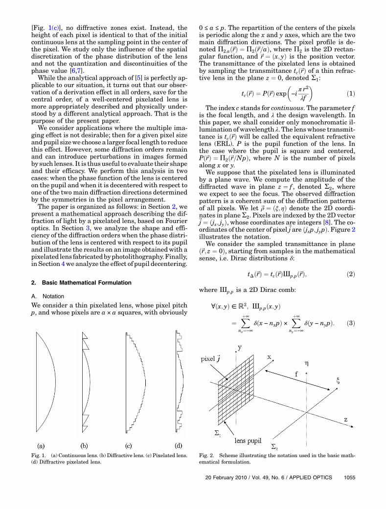
It is appropriate here to stress that the componentof interest to us, while affected by diffraction indeed,is a pixelated lens but not a diffractive lens (seeFig. 1). By “diffractive,” we mean that the design ofthe element resorts to phase wrapping, introducingzones and phase jumps, as is often necessary whendisplaying phase functions on a spatial light modu-lator [Fig. 1(b)]. The phase jumps are typically aninteger number of 2π at some appropriate designwavelength. The spatial light modulator pixels in ad-dition define regions of constant phase, so that thoselenses are both diffractive and pixelated [Fig. 1(d)].In our case, no phase wrapping was needed. Whilethe lens does consist in a set of closely packed pixels
[Fig. 1(c)], no diffractive zones exist. Instead, theheight of each pixel is identical to that of the initialcontinuous lens at the sampling point in the center ofthe pixel. We study only the influence of the spatialdiscretization of the phase distribution of the lensand not the quantization and discontinuities of thephase value [6,7].While the analytical approach of [5] is perfectly ap-
plicable to our situation, it turns out that our obser-vation of a derivation effect in all orders, save for thecentral order, of a well-centered pixelated lens ismore appropriately described and physically under-stood by a different analytical approach. That is thepurpose of the present paper.We consider applications where the multiple ima-
ging effect is not desirable; then for a given pixel sizeandpupil sizewe choosea larger focal length to reducethis effect. However, some diffraction orders remainand can introduce perturbations in images formedby such lenses. It is thususeful to evaluate their shapeand their efficacy. We perform this analysis in twocases: when the phase function of the lens is centeredon the pupil and when it is decentered with respect toone of the two main diffraction directions determinedby the symmetries in the pixel arrangement.The paper is organized as follows: in Section 2, we
present a mathematical approach describing the dif-fraction of light by a pixelated lens, based on Fourieroptics. In Section 3, we analyze the shape and effi-ciency of the diffraction orders when the phase distri-bution of the lens is centered with respect to its pupiland illustrate the results on an image obtainedwith apixelated lens fabricatedbyphotolithography.Finally,in Section 4we analyze the effect of pupil decentering.
2. Basic Mathematical Formulation
A. Notation
We consider a thin pixelated lens, whose pixel pitchp, and whose pixels are a × a squares, with obviously
0 ≤ a ≤ p. The repartition of the centers of the pixelsis periodic along the x and y axes, which are the twomain diffraction directions. The pixel profile is de-noted Π2;að~rÞ ¼ Π2ð~r=aÞ, where Π2 is the 2D rectan-gular function, and ~r ¼ ðx; yÞ is the position vector.The transmittance of the pixelated lens is obtainedby sampling the transmittance tcð~rÞ of a thin refrac-tive lens in the plane z ¼ 0, denoted Σ1:
tcð~rÞ ¼ Pð~rÞ exp�−i
π r2λf
�ð1Þ
The index c stands for continuous. The parameter fis the focal length, and λ the design wavelength. Inthis paper, we shall consider only monochromatic il-lumination of wavelength λ. The lenswhose transmit-tance is tcð~rÞ will be called the equivalent refractivelens (ERL). P is the pupil function of the lens. Inthe case where the pupil is square and centered,Pð~rÞ ¼ Π2ð~r=NpÞ, where N is the number of pixelsalong x or y.
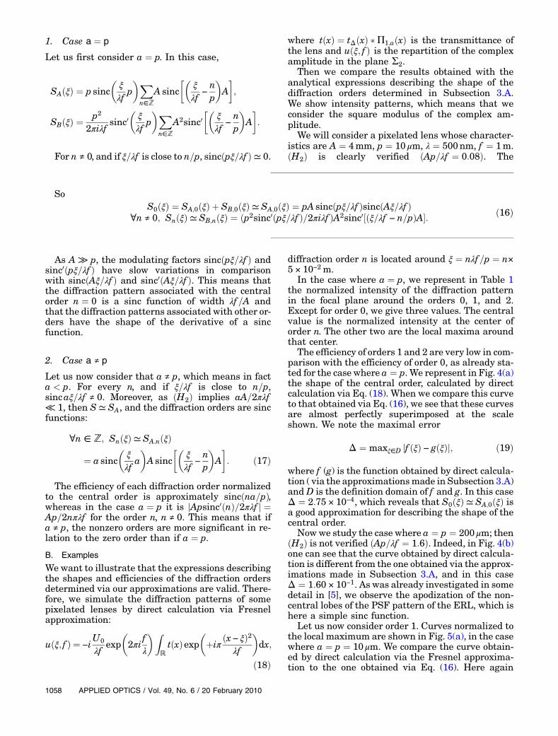
We suppose that the pixelated lens is illuminatedby a plane wave. We compute the amplitude of thediffracted wave in plane z ¼ f , denoted Σ2, wherewe expect to see the focus. The observed diffractionpattern is a coherent sum of the diffraction patternsof all pixels. We let ~ρ ¼ ðξ; ηÞ denote the 2D coordi-nates in planeΣ2. Pixels are indexed by the 2D vector~j ¼ ðjx; jyÞ, whose coordinates are integers [8]. The co-ordinates of the center of pixel~j are ðjxp; jypÞ. Figure 2illustrates the notation.
We consider the sampled transmittance in planeð~r; z ¼ 0Þ, starting from samples in the mathematicalsense, i.e. Dirac distributions δ:
In a pixelated lens, each sample of tc is in fact thecenter of a uniform pixel whose transmittance isequal to the sampled value. If U0 is the amplitudeof the incident plane wave, the complex amplitudein the plane Σ1 of the pixelated lens is U0 tð~rÞ with
tð~rÞ ¼ tΔð~rÞ �Π2;að~rÞ: ð4Þ
B. Assumptions about Fresnel Numbers
Here we introduce the Fresnel generalized number[9] (FGN):
FGN ¼ r20λf ;
where r0 is the radius of the smallest circular pupilthat contains the pupil of the pixel. As the pixel pupilis an a × a square, r0 ¼ a
ffiffiffi2
p=2. We assume that the
FGN for one pixel is much smaller than typically 1,which is a common criterion for the validity of theFraunhofer approximation. This hypothesis will becalled ðH1Þ and will be written as follows:
Hypothesis ðH1Þ: FGN ¼ a2
2λf ≪ 1:
In this study, our concern is about pixels whose sizea ≤ p ≤ 100 μm and focal lengths f ≥ 10 cm; then invisible light ðH1Þ is easily verified, since a2=2λf can-not exceed 0.1 for λ ¼ 0:5 μm. We will thus assume inthe rest of the paper that we are in the Fraunhoferdiffraction regime for pixel diffraction and that wecan write the Fresnel integral using the Fraunhoferapproximation for the central pixel diffraction at thedistance f :
u~0ð~ρÞ ¼ −iU0
λf tcð~0Þ exp�2πi fλ þ iπ ‖~ρ‖
2
λf
�~Π2;a
�~ρλf
�:
ð5Þ~Π2;a is the Fourier transform of Π2;a: ~Π2;að~ρ=λf Þ ¼a2sincðaξ=λf Þsincðaη=λf Þ. The diffracted field asso-ciated with the pixel~j is obtained by translation:
u~jð~ρÞ ¼ −iU0
λf tcð~jpÞ exp�2πi fλ þ iπ ‖~ρ−
~jp‖2
λf
�
× ~Π2;a
�~ρ −~jpλf
�: ð6Þ
We introduce the following auxiliary function:
f~jð~ρÞ≜Pð~jpÞ exp�−2iπ
~jp ·~ρλf
�~Π2;a
�~ρ −~jpλ f
�ð7Þ
Then, from Eq. (1),
u~jð~ρÞ ¼ −iU0
λf exp�2πiλ
�f þ ‖~ρ‖2
2f
��f~jð~ρÞ: ð8Þ
The complex amplitude in the plane Σ2 resultsfrom the interferences between the diffractionpatterns of all pixels and is thus
P~j∈ðℤ;ℤÞu~jð~ρÞ. Since
the term preceding f~jð~ρÞ in Eq. (8) is not pixel depen-dant, we focus on
P~j∈ðℤ;ℤÞf~jð~ρÞ. We have
Sð~ρÞ ¼X~j∈ℤ2
f~jð~ρÞ ¼X~j∈ℤ2
Pð~jpÞ exp�−2πi
~jp ·~ρλf
�
× ~Π2;a
�~ρ −~jpλf
�: ð9Þ
We introduce a second assumption:
Hypothesis ðH2Þ:Apλf ≪ 1;
where A ¼ Np is the lens pupil width along the x or yaxis. We assume that the lens pupil is contained in anA × A square. The ERL point spread function (PSF)width is then of the order of λf =A. Then ðH2Þ meansphysically that the pixel pitch p is much smaller thanthe width of the PSF associated with the ERL. Wenote that if ðH2Þ is verified, then ðH1Þ is also verified,since obviously Np2 ≥ a2=2. Moreover ðH2Þ implies,for any pixel ~j inside the pupil, ‖~j‖p=λf ≤ A=λf ≪1=p. Π2;a is contained in a p × p square. Its Fouriertransform ~Π2;a is therefore wider than 1=p. In thecase where the pixels are a × a squares with p ¼ a,1=p is exactly the central lobe half-width of ~Π2;a.
One may comment that the FGN for the whole lenspupil A2=2λf , as opposed to that of a single pixel, isnot smaller than unity. For a lens to show a substan-tial focusing power, it should on the contrary be lar-ger than unity. Hypothesis ðH2Þ assumes that thegeometrical average between the pixel FGN andthe lens FGN is significantly smaller than unity.In other words, whereas ðH1Þ amounts to assumingthe pixel size to be much smaller than its own diffrac-tion pattern in the focal plane, ðH2Þ relates to thecase where the whole lens size is much smaller thanthe pixel diffraction pattern. This assumption willnow be used to derive a physical interpretation ofthe diffraction order built up by the interferencebetween pixel diffraction patterns of Eq. (9).
C. Expanding the Diffraction Pattern of Individual Pixels
For simplicity’s sake, we restrict the following calcu-lation in this section to one dimension, but it can beeasily extended to two (see Appendix A). The 1D rec-tangular function of width a is denoted Π1;a, and itsFourier transform is denoted ~Π1;a:ðH2Þ implies thatthe variations of ~Π1;a between ξ=λf and ðξ − jpÞ=λfare small enough to assume that ~Π1;a½ðξ − jpÞ=λf �can be approximated by its first-order Taylor expan-sion around ξ=λf :
In other words, the diffraction pattern by one pixelin plane Σ2 can be expanded linearly over a distanceof the order of the pixelated lens pupil. Then, ifШp isa 1D Dirac comb,
∀x ∈ ℝ; ШpðxÞ ¼Xþ∞
nx¼−∞
δðx − nxpÞ: ð11Þ
Equation (9) becomes, after straightforwardalgebra,
SðξÞ ¼ FT�PðxÞШpðxÞ
�ξ=λf
~Π1;a
� ξλf
�
−1λf FT
�xPðxÞШpðxÞ
�ξ=λf
~Π01;a
� ξλf
�; ð12Þ
where FT stands for Fourier transform. Another wayto write Eq. (12) is
SðξÞ ¼�~P �Ш1=p
�ξ=λf
~Π1;a
� ξλf
�
þ 12πiλf
�~P0 �Ш1=p
�ξ=λf
~Π01;a
� ξλf
�: ð13Þ
Equation (13) can also be written as
SðξÞ ¼ SAðξÞ þ SBðξÞ ð14Þ
with
SAðξÞ ¼Xn∈ℤ
SA;n
� ξλf
�¼ ~Π1;a
� ξλf
�Xn∈ℤ
~P
� ξλf −
np
�;
SBðξÞ ¼Xn∈ℤ
SB;n
� ξλf
�¼
~Π01;a
�ξλf
�
2πiλfXn∈ℤ
~P0� ξλf −
np
�:
SAðξÞ is a sum of the lens pupil diffraction patternslocated at each diffraction order n of the pixel grat-ing, modulated by the pixel diffraction pattern. SBðξÞis a sum of the derivatives of the lens pupil diffrac-tion patterns located at each diffraction order n of thepixel grating, modulated by the derivative of thepixel diffraction pattern in the ξ direction.We also use the following notation:
SðξÞ ¼Xn∈ℤ
Snðξλf Þ
with ∀n ∈ ℤ; Snð ξλfÞ ¼ SA;nð ξλfÞ þ SB;nð ξλfÞ:To summarize, in this section, we have written SðξÞ
as a sum of diffraction patterns associated with dif-fraction orders, after having first expanded ~Π1;a½ðξ −jpÞ=λf � to first order around ξ=λf and written Eq. (9)in terms of Fourier transforms; this led us to an ex-pression including convolution by a Dirac comb. EachDirac function of the comb stands for a diffractionorder, whose shape will be analyzed in the followingsections. InSection3westudythecasewhere thepixe-lated lens is centered in the pupil, and in Section 4 westudy the case where this lens is decentered inthe pupil.
3. Shape of Diffraction Orders for a Pixelated LensCentered in the Pupil
A. Analysis
Still considering the 1D case, the expression of thepupil is PðxÞ ¼ Π1;AðxÞ. We note that sincðxÞ ¼sinðπxÞ=πx. Then
SAðξÞ ¼ a sinc�
ξλf a
� Pn∈ℤ
A sinc��
ξλf −
np
�A
�;
SBðξÞ ¼ a2
2πiλf sinc0�
ξλf a
� Pn∈ℤ
A2sinc0��
ξλf −
np
�A
�:
ð15Þ
In Figure 3, we show the shape of the sinc functionand the shape of its derivative.
We notice in Eqs. (15) that the SB to SA weightingfactor ratio is aA=2πλf , which is low according toðH2Þ. We will analyze the shape and efficiency ofthe diffraction orders, considering two cases: the casewhere a ¼ p and the case where a ≠ p.
Fig. 3. (Color online) Shape of the sinc function and shape of thederivative of the sinc function.
As A ≫ p, the modulating factors sincðpξ=λf Þ andsinc0ðpξ=λf Þ have slow variations in comparisonwith sincðAξ=λf Þ and sinc0ðAξ=λf Þ. This means thatthe diffraction pattern associated with the centralorder n ¼ 0 is a sinc function of width λf =A andthat the diffraction patterns associated with other or-ders have the shape of the derivative of a sincfunction.
2. Case a ≠ p
Let us now consider that a ≠ p, which means in facta < p. For every n, and if ξ=λf is close to n=p,sincaξ=λf ≠ 0. Moreover, as ðH2Þ implies aA=2πλf≪ 1, then S≃ SA, and the diffraction orders are sincfunctions:
∀n ∈ ℤ; SnðξÞ≃ SA;nðξÞ
¼ a sinc� ξλf a
�A sinc
�� ξλf −
np
�A
�: ð17Þ
The efficiency of each diffraction order normalizedto the central order is approximately sincðna=pÞ,whereas in the case a ¼ p it is jApsinc0ðnÞ=2πλf j ¼Ap=2nπλf for the order n, n ≠ 0. This means that ifa ≠ p, the nonzero orders are more significant in re-lation to the zero order than if a ¼ p.
B. Examples
We want to illustrate that the expressions describingthe shapes and efficiencies of the diffraction ordersdetermined via our approximations are valid. There-fore, we simulate the diffraction patterns of somepixelated lenses by direct calculation via Fresnelapproximation:
uðξ; f Þ ¼ −iU0
λf exp�2πi fλ
�ZℝtðxÞexp
�þiπ ðx− ξÞ2
λf
�dx;
ð18Þ
where tðxÞ ¼ tΔðxÞ �Π1;aðxÞ is the transmittance ofthe lens and uðξ; f Þ is the repartition of the complexamplitude in the plane Σ2.
Then we compare the results obtained with theanalytical expressions describing the shape of thediffraction orders determined in Subsection 3.A.We show intensity patterns, which means that weconsider the square modulus of the complex am-plitude.
We will consider a pixelated lens whose character-istics are A ¼ 4mm, p ¼ 10 μm, λ ¼ 500nm, f ¼ 1m.ðH2Þ is clearly verified ðAp=λf ¼ 0:08Þ. The
diffraction order n is located around ξ ¼ nλf =p ¼ n×5 × 10⁻² m.
In the case where a ¼ p, we represent in Table 1the normalized intensity of the diffraction patternin the focal plane around the orders 0, 1, and 2.Except for order 0, we give three values. The centralvalue is the normalized intensity at the center oforder n. The other two are the local maxima aroundthat center.
The efficiency of orders 1 and 2 are very low in com-parison with the efficiency of order 0, as already sta-ted for the case where a ¼ p. We represent in Fig. 4(a)the shape of the central order, calculated by directcalculation via Eq. (18). When we compare this curveto that obtained via Eq. (16), we see that these curvesare almost perfectly superimposed at the scaleshown. We note the maximal error
Δ ¼ maxξ∈D jf ðξÞ − gðξÞj; ð19Þ
where f (g) is the function obtained by direct calcula-tion ( via the approximationsmade in Subsection 3.A)and D is the definition domain of f and g. In this caseΔ ¼ 2:75 × 10−4, which reveals that S0ðξÞ≃ SA;0ðξÞ isa good approximation for describing the shape of thecentral order.
Nowwe study the case where a ¼ p ¼ 200 μm; thenðH2Þ is not verified ðAp=λf ¼ 1:6Þ. Indeed, in Fig. 4(b)one can see that the curve obtained by direct calcula-tion is different from the one obtained via the approx-imations made in Subsection 3.A, and in this caseΔ ¼ 1:60 × 10−1. As was already investigated in somedetail in [5], we observe the apodization of the non-central lobes of the PSF pattern of the ERL, which ishere a simple sinc function.
Let us now consider order 1. Curves normalized tothe local maximum are shown in Fig. 5(a), in the casewhere a ¼ p ¼ 10 μm. We compare the curve obtain-ed by direct calculation via the Fresnel approxima-tion to the one obtained via Eq. (16). Here again
the curves associated with f and g match quasi per-fectly, as Δ ¼ 4:13 × 10−3.Finally, we consider the case where a ¼
p ¼ 200 μm.We represent the shape of the first order,located around ξ ¼ 2:5 × 10⁻³ m in Fig. 5(b). We verifythat the curves associated with f and g do not matchin this case, where ðH2Þ is not clearly verified:Δ ¼ 3:18 × 10−1. Nevertheless, our approximationstill provides a fair first grasp at the phenomenon.Let us now consider the case where a ≠ p. Choosing
again p ¼ 10 μm, we observe in Fig. 6 the diffractionpattern associated with order 1 obtained with a ¼p=2 ¼ 5 μm. The curves associated with f and g areobtained, respectively, via Eqs. (17) and (18) match:Δ ¼ 3:50 × 10−4.In this section, where the pixelated lens is centered
on the pupil, we verified through different numeri-cal examples that the approximations made inSubsection 3.A are reasonable when ðH2Þ is verified,
as the error functionΔ is smaller than 1% in all casesstudied.
C. Experimental Results
The experiment described here is intended to illus-tratetheresultsobtained inSubsection3.A.A2Dpixe-lated lens was fabricated with the characteristicsf ¼ 1m and a ¼ p ¼ 20 μm, and the side length ofthe square pupil of this lens is A ¼ 2mm. We illumi-nated this lens with an expanded He–Ne laser:λ≃ 633nm. ðH2Þ isverifiedas ðAp=λf ≃ 0:06Þ.Figure7shows the diffraction pattern, observed with a linearcamera,with the central order considerably saturatedinspiteof the fact that thecentralpartof the figurehasbeen dimmed, and the first orders in the x and y direc-tions. The size of Figure 7 is 70mm × 70mm. As thedynamic range of the camera used for the photographwas not large enough to clearly show the shape of thezero and nonzero orders simultaneously, we tookpictures of the diffraction orders separately, with
Fig. 4. (Color online) Central order of a centered pixelated lens:(a) a ¼ p ¼ 10 μm, (b) a ¼ p ¼ 200 μm.
Fig. 5. (Color online) First order of a centered pixelated lens:(a) a ¼ p ¼ 10 μm, (b) a ¼ p ¼ 200 μm.
Table 1. Normalized Intensity of Orders 0, 1, and 2
different exposure times. Then, Figure 8 shows moreprecisely the shape of the central order. One easilyidentifies the product of two sinc functions. Figure 9isamagnifiedversionof thezoneinsidetheuppersolidsquare in Fig. 7, i.e., order~j ¼ ð0; 1Þ. The size of Fig. 8and 9 is 10mm × 10mm. We also show in Fig. 10 thevertical cross section of the diffraction order shownin Fig. 9, and we compare it with the square modulusof thederivativeofasinc functionwiththeappropriateparameters. The similitude between measure andapproximation confirms the results obtained inSubsection 3.A.
4. Decentered Pixelated Lens
A. Analysis
We propose to study the effect of decentering the lenspupil along the x direction inside the pupil plane,which is equivalent to translating the phase functionof the lens in relation to a fixed pupil. X is the trans-lation of the center of the lens along x.
Equation (1) in one dimension then becomestcðxÞ ¼ Π1;AðxÞ expð−iπðx − XÞ2=λf Þ, which leads usto consider a different expression for S:
SAðξÞ ¼ a sinc�a ξ
λf
�Pn∈ℤ
A sinc��
ξλf −
Xλf −
np
�A
�;
SBðξÞ ¼ a2
2π iλf sinc0�
ξλf a
� Pn∈ℤ
A2sinc0��
ξλf −
Xλf −
np
�A
�:
ð20ÞWe show how to get this result in Appendix B. The
diffraction pattern associated with the order n islocated around ξ ¼ nλf =pþ X .
We will consider two cases that depend on thevalue of X.
1. Lens Decentering an Integer Multiple of theDiffracted Order Spacing
If ∃nX ; − X=λf ¼ nX=p, i.e., if the lens decentering inthe pupil is an integer multiple of the diffracted order
Fig. 6. (Color online) First order of a centered pixelated lens:a ¼ p=2 ¼ 5 μm.
Fig. 7. (Color online) Observation of the repartition of light in thefocal plane of a pixelated lens. Dashed frame, the central order;solid frame, order (0,1).
Fig. 8. Observation of the shape of the central order.
spacing in the plane Σ2, we apply the same develop-ment as in Section 3. One may note that this situa-tion is in fact trivial, because, as can be shown easily,sampling the continuous equivalent refractive lens ofEq. (1) at sampling points jxp after shifting it byλf nx=p changes only a constant in the sampled trans-mittance tΔ. Nevertheless, we assume here that theorder centered at ξ ¼ 0 is n ¼ nX and not n ¼ 0.Then when a ¼ p,
2. Lens Decentering Not an Integer Multiple of theDiffracted Order Spacing
Let us now consider the case in which the lens decen-tering in the pupil is not an integer multiple of thediffracted order spacing 1=p in the focal plane. Forevery n, and if ξ is close to nλf =pþ X, sincaξ=λf ≠ 0. Moreover, as ðH2Þ implies aA=2πλf ≪ 1,then S≃ SA:
it is seen from Eq. (23) that ceilð2p=aÞ diffraction pat-terns associated with diffraction orders are locatedwithin the main lobe of sincðξa=λf Þ. We can approx-imate that these central orders have large efficien-cies in comparison with other orders. However, onecan once more note that these other orders are notweighted by aA=2πλf, which means that the noncen-tral orders are more significant in relation to the cen-tral order(s) than if a ¼ p and the lens phase functionwere centered on an integer multiple of the diffractedorder spacing in the focal plane Σ2. Every order ishere a sinc function. When a ¼ p, two diffractionorders are significant: the orders floorð−pX=λf Þand ceilð−pX=λf Þ.B. Examples
As in Subsection 3.B, we want to illustrate the valid-ity of the expressions describing the shapes and effi-ciencies of the diffraction orders determined via ourapproximations in Subsection 4.A. Therefore, we co-mpare the results obtained via Eq. (18) with theanalytical expressions describing the shape of thediffraction orders determined in Subsection 4.A. In
this section, the pupil is fixed and the lens is decen-tered. We keep the same lens characteristics: A ¼4mm, p ¼ 10 μm, λ ¼ 500nm, f ¼ 1m; so ðH2Þ isclearly verified.
In Table 2, we simulate the case where a ¼ p andX ¼ λf =ð3pÞ. Here the lens decentering X is not aninteger multiple of the diffracted order spacingλf =p in the focal plane. According to Subsection 4.A,there are ceilð2p=aÞ ¼ 2 main orders in the focalplane: floorð−pX=λf Þ ¼ −1 and ceilð−pX=λf Þ ¼ 0. In-deed, we can observe these two orders in Table 2around ξ ¼ X ¼ λf =3p ¼ 16:7mm (order 0) andξ ¼ X ¼ λf =3p − λf =p ¼ −33:3mm (order −1). Onecan also notice that order 1 is more significant inTable 2 than in Table 1, which is, as we have seen
Fig. 10. (Color online) Vertical cross section of the image in Fig. 9.The pixel pitch distance is 45 μm.
Table 2. Normalized Intensity of Orders −1, 0 and 1 in the FocalPlane of a Decentered Pixelated Lensa
in Subsection 4.A, a consequence of the fact that thisorder is not weighted by aA=2πλf as in the case of theTable 1.Now we zoom in around the order −1 in Fig. 11. We
compare the curves obtained via Eqs. (18) and (23).Here Δ ¼ 3:34 × 10−3; then SA;−1 is a good approxi-mation of the shape of the order −1.Now we study the case where a ¼ p=2 and
X ¼ 2λf =5p, represented in Fig. 12. We superim-posed the curve associated with sincðaξ=λf Þ to verifythat ceilð2p=aÞ ¼ 4 orders are located within themain lobe of sincðaξ=λf Þ as expected. One can noticethat in certain configurations, some orders located inthe secondary lobes of sincðaξ=λf Þ can be brighterthan some orders located in the main lobe.
Let us sum up the results obtained in this section.When the center of the phase function is shifted withrespect to optical axis along the x axis, the brightestorders in the focal plane are located on both sides ofthe orthogonal projection of the lens center on ξ-axis.The number of significant orders depends on the ra-tio a=p. The shapes of all orders are generally similarto the PSF pattern of the equivalent refractive cen-tered lens, except in the degenerate case where a ¼ pand the lens decentering is an integer multiple of thediffracted order spacing. Indeed, that case reduces tothat of a centered lens.
5. Conclusion
We have analyzed the shape and efficiency of the dif-fraction orders observed in the focal plane of a pixe-lated lens when the pixel size is much smaller thanthe PSF of the ERL.
When the pixelated lens is centered, and when thepixel width a is equal to the pixel pitch p, we haveshown that the central order whose shape is wellknown to be identical to that of the ERL is muchbrighter than the other orders and that the shapesof the other orders are approximately the derivativeof this PSF.When the pixel width is sufficiently smal-ler than the pixel pitch, the shapes of all diffractionorders are similar to the PSF pattern of the ERL.
We have also shown that decentering the phasefunction of the lens along the x or y axis, with respectto the pupil, has a significant influence on the shapeand efficiency of the diffraction orders.
We especially focused on pixelated lenses withsquare pixels and a square pupil, but our approachcan be applied to different pupil and pixel shapes.Moreover, our study was about decentering the lensalong the x or y axis and is trivially generalized to anarbitrary 2D decentering.
Appendix A
Starting again from Eq. (9),
S ¼X
~j∈ðℤ;ℤÞf~jð~ρÞ ¼
X~j∈ðℤ;ℤÞ
Pð~jpÞ exp�−2iπ
~jp ·~ρλf
�
× ~Π2;a
�~ρ −~jpλf
�; ðA1Þ
ðH2Þ implies, for any pixel j inside the pupil,‖~j p=λf‖ ≤ 1=p.
Then
~Πa
�~ρ −~jpλf
�≃ ~Πa
� ξλf ;
ηλf
�−jxpλf
∂ ~Π2;a
∂ξ
� ξλf ;
ηλf
�
−jyp
λf∂ ~Π2;a
∂η
� ξλf ;
ηλf
�: ðA2Þ
Equation (A1) then becomes
Fig. 11. (Color online) Order −1 in the focal plane of a decenteredpixelated lens: a ¼ p, X ¼ λf =ð3pÞ.
Fig. 12. (Color online) Normalized intensity in the focal plane of adecentered pixelated lens: a ¼ p=2, X ¼ 2λf =5p. (a) Curve asso-ciated with direct calculation; (b) curve associated withsincðaξ=λf Þ.
FT is here the 2D Fourier transform.Let us denote ~P0
ξ ¼ ∂~P=∂ξ, ~P0η ¼ ∂~P=∂η, ~Π0
2;a; ξ ¼∂ ~Π2;a=∂ξ, and ~Π0
2;a; η ¼ ∂ ~Π2;a=∂η:
SðξÞ ¼�~P �Шð1=p;1=pÞ
�~ρ=λf
~Π2;a
�~ρλf
�
þ 12πiλf
�~P0ξ �Шð1=p;1=pÞ
�~ρ=λf
~Π02;a;ξ
�~ρλf
�
þ 12πiλf
�~P0η �Шð1=p;1=pÞ
�~ρ=λf
~Π02;a;η
�~ρλf
�: ðA4Þ
This can also be written as
SðξÞ ¼ SAðξÞ þ SB;ξðξÞ þ SB;ηðξÞ
¼ ~Π2;a
�~ρλf
� X~n∈ðℤ;ℤÞ
~P
�~ρλf −
~np
�
þ~Π02;a;ξ
�~ρλf
�2πiλf
X~n∈ðℤ;ℤÞ
~P0ξ
�~ρλf −
~np
�
þ~Π02;a;η
�~ρλf
�2πiλf
X~n∈ðℤ;ℤÞ
~P0η
�~ρλf −
~np
�: ðA5Þ
The 2D vectors ~n ¼ ðnξ;nηÞ, whose coordinates areintegers, represent the diffraction orders.SA is a replication of the lens pupil diffraction pat-
tern in each diffraction order n of the pixel grating,modulated by the pixel diffraction pattern.SB;ξ (SB;η) is a replication of the derivative of the
lens pupil diffraction pattern along ξ (η) in each dif-fraction order ~n of the pixel grating, modulated bythe pixel diffraction pattern derivative in the ξ direc-tion (η direction).SA, SB;ξ, and SB;η can be analyzed the same way as
SA and SB in Sections 3 and 4.
Appendix B
We consider Eq. (1) in one dimension, when the pupilis translated along x, and X is the coordinate of thenew pupil center:
tcðxÞ ¼ PðxÞ expð−iπðx − XÞ2=λf Þ: ðB1Þ
Then we use the Fraunhofer approximation for thecentral pixel diffraction at distance f ,
u0ðξÞ ¼ −iU0
λf tcð0Þ exp�2πi fλ þ iπ ξ
2
λf
�~Π1;a
� ξλf
�;
ðB2Þ
and for the diffraction by the pixel jx at distance f , weget, replacing x with jxp in Eq. (B1),
ujxðξÞ ¼ −iU0
λf tcðjxpÞ ~Π1;a
�ξ − jxpλf
�
× exp�2πi fλ þ iπ ðξ − jxpÞ2
λf
�: ðB3Þ
If we designate
f jxðξÞ≜PðjxpÞ exp�−2iπ jxpξλf
�~Π1;a
�ξ − jxpλf
�
× exp�2iπXjxp
λf
�; ðB4Þ
then
ujxðξÞ ¼ −iU0
λf exp�2πiλ
�f þ ξ2
2f
��exp
�−i
πX2
λf
�f jxðξÞ:
ðB5Þ
As the term −ðiU0=λf Þ exp½ð2πi=λÞðf þ ρ2=2f Þ� expð−iπX2=λf Þf jxðξÞ is not pixel dependant, we focuson
P~j∈ℤf~jð~ρÞ:
SðξÞ ¼Xjx∈ℤ
f jxðξÞ ¼Xjx∈ℤ
PðjxpÞ exp�−2πi ξjxpλf
�
× ~Π1;a
�ξ − jxpλf
�exp
�2πi Xjxp
λf
�: ðB6Þ
Then to a first-order approximation
SðξÞ ¼ FT�PðxÞШpðxÞ
�ðξ−XÞ=λf
~Π1;a
� ξλf
�
−1λf FT
�xPðxÞШpðxÞ
�ðξ−XÞ=λf
~Π01;a
� ξλf
�: ðB7Þ
We notice that this expression would be obtained,in the centered case, with tcðxÞ ¼ PðxÞ expð−iπx2=λf Þexpð2iπxX=λf Þ. The term expð2iπxX=λf Þ represents aphase tilting, so we understand that within the con-text of our approximations, decentering this lens isequivalent to placing a thin prism before or after it.
2. E. Carcolé, J. Campos, I. Juvells, and S. Bosch, “Diffractionefficiency of low-resolution Fresnel encoded lenses,” Appl.Opt. 33, 6741–6746 (1994).
3. E. Carcolé, J. Campos, and S. Bosch, “Diffraction theory ofFresnel lenses encoded in low-resolution devices,” Appl.Opt. 33, 162–174 (1994).
4. E. Carcolé, J. Campos, I. Juvells, and J. R. de F. Moneo,“Diffraction theory of optimized low-resolution Fresnel en-coded lenses,” Appl. Opt. 34, 5952–5960 (1995).
5. V. Arrizon, E. Carreon, and L. A. Gonzalez, “Self-apodizationof low-resolution pixelated lenses,” Appl. Opt. 38, 5073–5077(1999).
6. G. J. Swanson, “The theory and design of multi-level diffrac-tive optical elements,” Binary Optics Technology, MIT Tech.Rep. 854 (MIT, 1989)
7. G. J. Swanson“Theoretical limits on the diffraction efficiencyof multilevel diffractive optical elements,” in Binary OpticsTechnology, MIT Tech. Rep. 914 (MIT, 1991).
8. This is compatible with a centered pupil of size N ×N pixelsonly if N is an odd integer. But the extension to even values ofN would be straightforward. However, the parity of N is aninessential factor in the present study and we shall not devel-op it in any detail.
9. S. Wang, E. Barnabeu, and J. Alda, “Unified and generalizedFresnel numbers,” Opt. Quantum Electron. 24, 1351–1358(1992).