Page 1
©2007 John Wiley & Sons, Inc. M P Groover, Fundamentals of Modern Manufacturing 3/e
SHAPING PROCESSES FOR PLASTICS
1. Properties of Polymer Melts
2. Extrusion
3. Production of Sheet, Film, and Filaments
4. Coating Processes
5. Injection Molding
6. Other Molding Processes
7. Thermoforming
8. Casting
9. Polymer Foam Processing and Forming
10.Product Design Considerations
Page 2
©2007 John Wiley & Sons, Inc. M P Groover, Fundamentals of Modern Manufacturing 3/e
Plastic Products
Plastics can be shaped into a wide variety of products: Molded parts Extruded sections Films Sheets Insulation coatings on electrical wires Fibers for textiles
Page 3
©2007 John Wiley & Sons, Inc. M P Groover, Fundamentals of Modern Manufacturing 3/e
More Plastic Products
In addition, plastics are often the principal ingredient in other materials, such as Paints and varnishes Adhesives Various polymer matrix composites
Many plastic shaping processes can be adapted to produce items made of rubbers and polymer matrix composites
Page 4
©2007 John Wiley & Sons, Inc. M P Groover, Fundamentals of Modern Manufacturing 3/e
Trends in Polymer Processing
Applications of plastics have increased at a much faster rate than either metals or ceramics during the last 50 years Many parts previously made of metals are
now being made of plastics Plastic containers have been largely
substituted for glass bottles and jars Total volume of polymers (plastics and
rubbers) now exceeds that of metals
Page 5
©2007 John Wiley & Sons, Inc. M P Groover, Fundamentals of Modern Manufacturing 3/e
Plastic Shaping Processes are Important
Almost unlimited variety of part geometries Plastic molding is a net shape process
Further shaping is not needed Less energy is required than for metals due to
much lower processing temperatures Handling of product is simplified during
production because of lower temperatures Painting or plating is usually not required
Page 6
©2007 John Wiley & Sons, Inc. M P Groover, Fundamentals of Modern Manufacturing 3/e
Two Types of Plastics
1. Thermoplastics Chemical structure remains unchanged
during heating and shaping More important commercially, comprising
more than 70% of total plastics tonnage
2. Thermosets Undergo a curing process during heating
and shaping, causing a permanent change (cross‑linking) in molecular structure
Once cured, they cannot be remelted
Page 7
©2007 John Wiley & Sons, Inc. M P Groover, Fundamentals of Modern Manufacturing 3/e
Classification of Shaping Processes
Extruded products with constant cross‑section Continuous sheets and films Continuous filaments (fibers) Molded parts that are mostly solid Hollow molded parts with relatively thin walls Discrete parts made of formed sheets and films Castings Foamed products
Page 8
©2007 John Wiley & Sons, Inc. M P Groover, Fundamentals of Modern Manufacturing 3/e
Polymer Melts
To shape a thermoplastic polymer it must be heated so that it softens to the consistency of a liquid
In this form, it is called a polymer melt Important properties of polymer melts:
Viscosity Viscoelasticity
Page 9
©2007 John Wiley & Sons, Inc. M P Groover, Fundamentals of Modern Manufacturing 3/e
Viscosity of Polymer Melts
Fluid property that relates shear stress to shear rate during flow
Due to its high molecular weight, a polymer melt is a thick fluid with high viscosity
Most polymer shaping processes involve flow through small channels or die openings Flow rates are often large, leading to high
shear rates and shear stresses, so significant pressures are required to accomplish the processes
Page 10
©2007 John Wiley & Sons, Inc. M P Groover, Fundamentals of Modern Manufacturing 3/e
Viscosity and Shear Rate
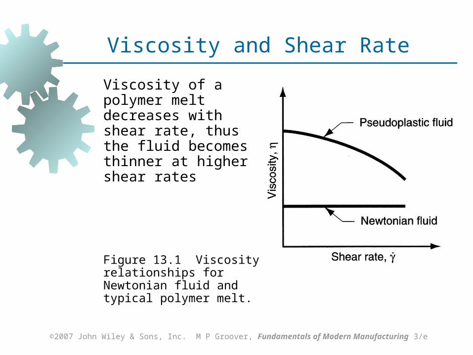
Viscosity of a polymer melt decreases with shear rate, thus the fluid becomes thinner at higher shear rates
Figure 13.1 Viscosity relationships for Newtonian fluid and typical polymer melt.
Page 11
©2007 John Wiley & Sons, Inc. M P Groover, Fundamentals of Modern Manufacturing 3/e
Viscosity and Temperature
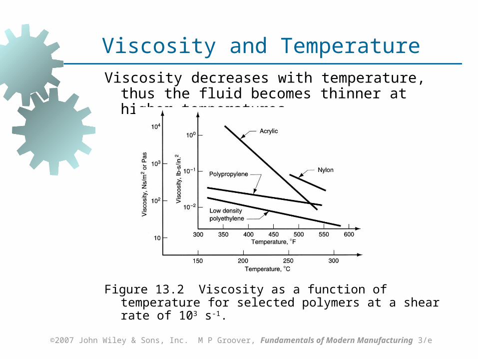
Viscosity decreases with temperature, thus the fluid becomes thinner at higher temperatures
Figure 13.2 Viscosity as a function of temperature for selected polymers at a shear rate of 103 s-1.
Page 12
©2007 John Wiley & Sons, Inc. M P Groover, Fundamentals of Modern Manufacturing 3/e
Viscoelasticity
Combination of viscosity and elasticity Possessed by both polymer solids and polymer
melts Example: die swell in extrusion, in which the
hot plastic expands when exiting the die opening
Page 13
©2007 John Wiley & Sons, Inc. M P Groover, Fundamentals of Modern Manufacturing 3/e
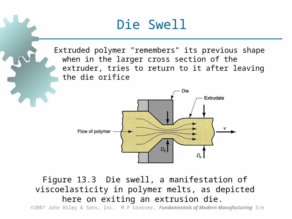
Extruded polymer "remembers" its previous shape when in the larger cross section of the extruder, tries to return to it after leaving the die orifice
Figure 13.3 Die swell, a manifestation of viscoelasticity in polymer melts, as depicted here on exiting an extrusion die.
Die Swell
Page 14
©2007 John Wiley & Sons, Inc. M P Groover, Fundamentals of Modern Manufacturing 3/e
Extrusion
Compression process in which material is forced to flow through a die orifice to provide long continuous product whose cross‑sectional shape is determined by the shape of the orifice
Widely used for thermoplastics and elastomers to mass produce items such as tubing, pipes, hose, structural shapes, sheet and film, continuous filaments, and coated electrical wire
Carried out as a continuous process; extrudate is then cut into desired lengths
Page 15
©2007 John Wiley & Sons, Inc. M P Groover, Fundamentals of Modern Manufacturing 3/e
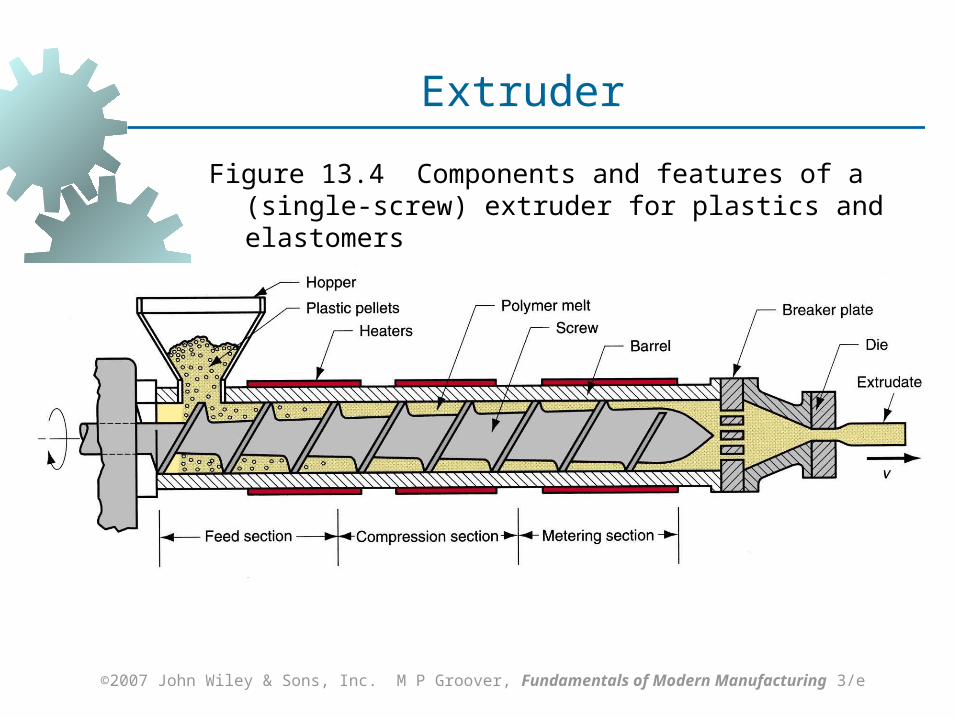
Extruder
Figure 13.4 Components and features of a (single‑screw) extruder for plastics and elastomers
Page 16
©2007 John Wiley & Sons, Inc. M P Groover, Fundamentals of Modern Manufacturing 3/e
Two Main Components of an Extruder
1. Barrel
2. Screw Die - not an extruder component
Special tool that must be fabricated for particular profile to be produced
Page 17
©2007 John Wiley & Sons, Inc. M P Groover, Fundamentals of Modern Manufacturing 3/e
Extruder Barrel
Internal diameter typically ranges from 25 to 150 mm (1.0 to 6.0 in.)
L/D ratios usually between 10 and 30: higher ratios for thermoplastics, lower ratios for elastomers
Feedstock fed by gravity onto screw whose rotation moves material through barrel
Electric heaters melt feedstock; subsequent mixing and mechanical working adds heat which maintains the melt
Page 18
©2007 John Wiley & Sons, Inc. M P Groover, Fundamentals of Modern Manufacturing 3/e
Extruder Screw
Divided into sections to serve several functions: Feed section - feedstock is moved from
hopper and preheated Compression section - polymer is
transformed into fluid, air mixed with pellets is extracted from melt, and material is compressed
Metering section - melt is homogenized and sufficient pressure developed to pump it through die opening
Page 19
©2007 John Wiley & Sons, Inc. M P Groover, Fundamentals of Modern Manufacturing 3/e
Extruder Screw
Figure 13.5 Details of an extruder screw inside the barrel.
Page 20
©2007 John Wiley & Sons, Inc. M P Groover, Fundamentals of Modern Manufacturing 3/e
Die End of Extruder
Progress of polymer melt through barrel leads ultimately to the die zone
Before reaching die, the melt passes through a screen pack - series of wire meshes supported by a stiff plate containing small axial holes
Functions of screen pack: Filter out contaminants and hard lumps Build pressure in metering section Straighten flow of polymer melt and remove
its "memory" of circular motion from screw
Page 21
©2007 John Wiley & Sons, Inc. M P Groover, Fundamentals of Modern Manufacturing 3/e
Melt Flow in Extruder
As screw rotates inside barrel, polymer melt is forced to move forward toward die; as in an Archimedian screw
Principal transport mechanism is drag flow, Qd, resulting from friction between the viscous liquid and the rotating screw
Compressing the polymer melt through the die creates a back pressure that reduces drag flow transport (called back pressure flow, Qb )
Resulting flow in extruder is Qx = Qd – Qb
Page 22
©2007 John Wiley & Sons, Inc. M P Groover, Fundamentals of Modern Manufacturing 3/e
Die Configurations and Extruded Products
The shape of the die orifice determines the cross‑sectional shape of the extrudate
Common die profiles and corresponding extruded shapes: Solid profiles Hollow profiles, such as tubes Wire and cable coating Sheet and film Filaments
Page 23
©2007 John Wiley & Sons, Inc. M P Groover, Fundamentals of Modern Manufacturing 3/e
Extrusion of Solid Profiles
Regular shapes such as Rounds Squares
Irregular cross sections such as Structural shapes Door and window moldings Automobile trim House siding
Page 24
©2007 John Wiley & Sons, Inc. M P Groover, Fundamentals of Modern Manufacturing 3/e
Extrusion Die for Solid Cross Section
Figure 13.8 (a) Side view cross‑section of an extrusion die for solid regular shapes, such as round stock; (b) front view of die, with profile of extrudate. Die swell is evident
in both views.
Page 25
©2007 John Wiley & Sons, Inc. M P Groover, Fundamentals of Modern Manufacturing 3/e
Hollow Profiles
Examples: tubes, pipes, hoses, and other cross‑sections containing holes
Hollow profiles require mandrel to form the shape
Mandrel held in place using a spider Polymer melt flows around legs supporting
the mandrel to reunite into a monolithic tube wall
Mandrel often includes an air channel through which air is blown to maintain hollow form of extrudate during hardening
Page 26
©2007 John Wiley & Sons, Inc. M P Groover, Fundamentals of Modern Manufacturing 3/e
Extrusion Die for Hollow Shapes
Figure 13.10 Side view cross‑section of extrusion die for shaping hollow cross‑sections such as tubes and pipes; Section A‑A is a front view cross‑section showing how the mandrel is held in place; Section B‑B shows the tubular cross‑section just prior to exiting the die; die swell causes an enlargement of the diameter.
Page 27
©2007 John Wiley & Sons, Inc. M P Groover, Fundamentals of Modern Manufacturing 3/e
Wire and Cable Coating
Polymer melt is applied to bare wire as it is pulled at high speed through a die A slight vacuum is drawn between wire and
polymer to promote adhesion of coating Wire provides rigidity during cooling - usually
aided by passing coated wire through a water trough
Product is wound onto large spools at speeds up to 50 m/s (10,000 ft/min)
Page 28
©2007 John Wiley & Sons, Inc. M P Groover, Fundamentals of Modern Manufacturing 3/e
Extrusion Die for Coating Wire
Figure 13.11 Side view cross‑section of die for coating of electrical wire by extrusion.
Page 29
©2007 John Wiley & Sons, Inc. M P Groover, Fundamentals of Modern Manufacturing 3/e
Polymer Sheet and Film
Film - thickness below 0.5 mm (0.020 in.) Packaging - product wrapping material,
grocery bags, and garbage bags Stock for photographic film Pool covers and liners for irrigation ditches
Sheet - thickness from 0.5 mm (0.020 in.) to about 12.5 mm (0.5 in.) Flat window glazing Thermoforming stock
Page 30
©2007 John Wiley & Sons, Inc. M P Groover, Fundamentals of Modern Manufacturing 3/e
Materials for Polymer Sheet and Film
All thermoplastic polymers Polyethylene, mostly low density PE Polypropylene Polyvinylchloride Cellophane
Page 31
©2007 John Wiley & Sons, Inc. M P Groover, Fundamentals of Modern Manufacturing 3/e
Sheet and Film Production Processes
Most widely used processes are continuous, high production operations
Processes include: Slit‑Die Extrusion of Sheet and Film Blown‑Film Extrusion Process Calendering
Page 32
©2007 John Wiley & Sons, Inc. M P Groover, Fundamentals of Modern Manufacturing 3/e
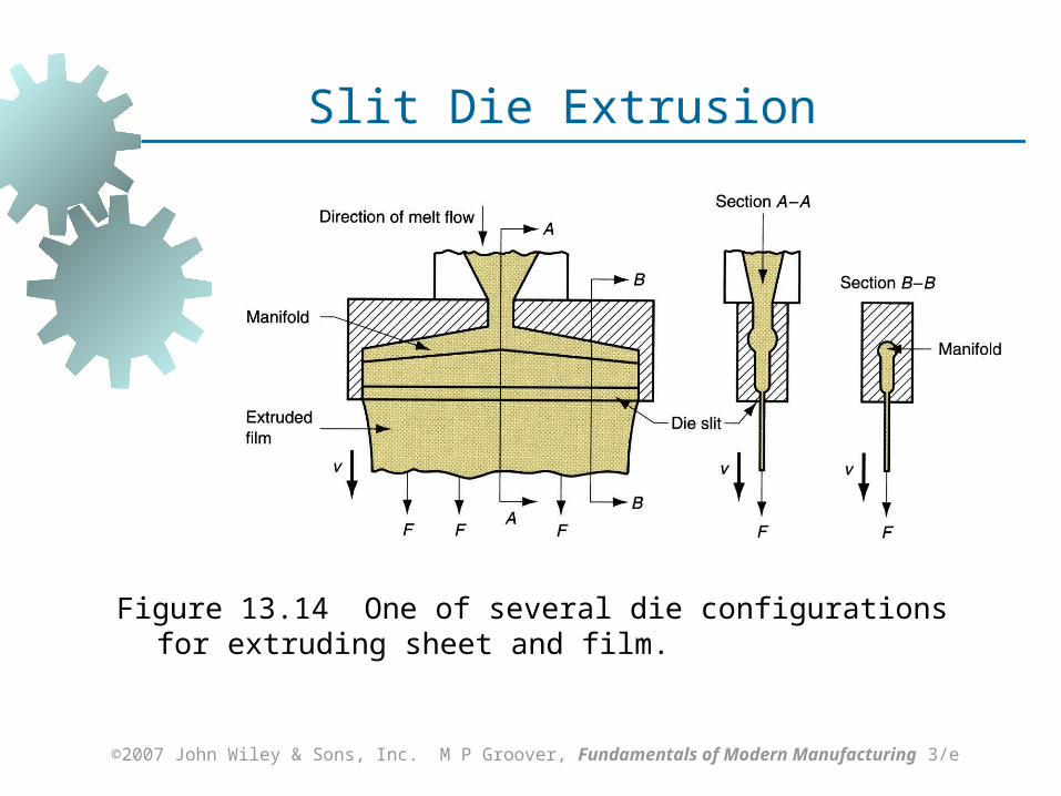
Slit‑Die Extrusion of Sheet and Film
Production of sheet and film by conventional extrusion, using a narrow slit as the die opening
Slit may be up to 3 m (10 ft) wide and as narrow as around 0.4 mm (0.015 in)
A problem is uniformity of thickness throughout width of stock, due to drastic shape change of polymer melt as it flows through die
Edges of film usually must be trimmed because of thickening at edges
Page 33
©2007 John Wiley & Sons, Inc. M P Groover, Fundamentals of Modern Manufacturing 3/e
Figure 13.14 One of several die configurations for extruding sheet and film.
Slit Die Extrusion
Page 34
©2007 John Wiley & Sons, Inc. M P Groover, Fundamentals of Modern Manufacturing 3/e
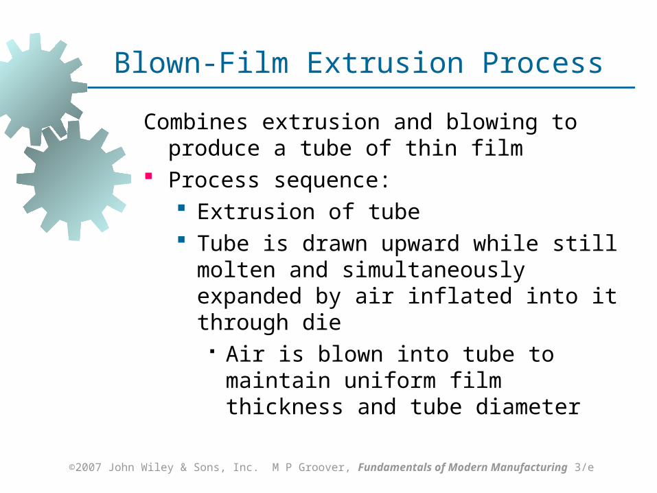
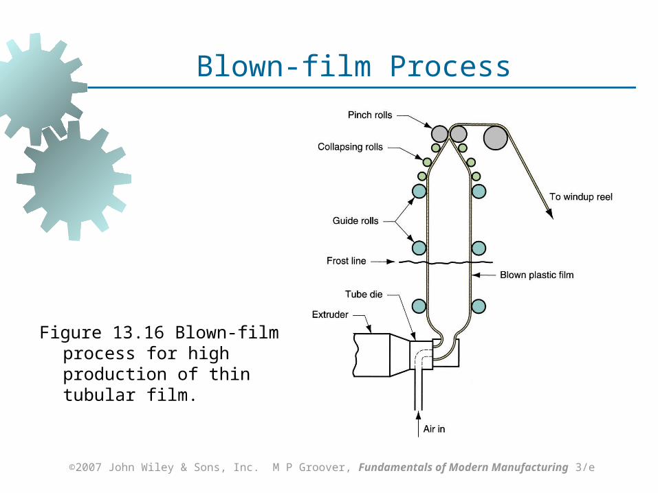
Blown‑Film Extrusion Process
Combines extrusion and blowing to produce a tube of thin film
Process sequence: Extrusion of tube Tube is drawn upward while still molten and
simultaneously expanded by air inflated into it through die
Air is blown into tube to maintain uniform film thickness and tube diameter
Page 35
©2007 John Wiley & Sons, Inc. M P Groover, Fundamentals of Modern Manufacturing 3/e
Figure 13.16 Blown‑film process for high production of thin tubular film.
Blown-film Process
Page 36
©2007 John Wiley & Sons, Inc. M P Groover, Fundamentals of Modern Manufacturing 3/e
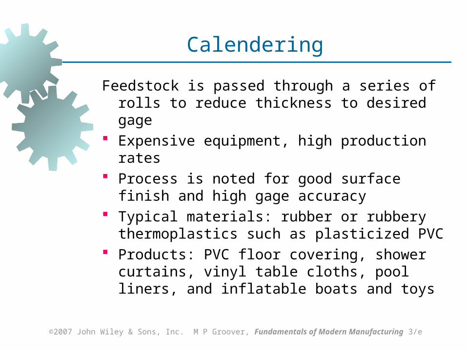
Calendering
Feedstock is passed through a series of rolls to reduce thickness to desired gage
Expensive equipment, high production rates Process is noted for good surface finish and
high gage accuracy Typical materials: rubber or rubbery
thermoplastics such as plasticized PVC Products: PVC floor covering, shower curtains,
vinyl table cloths, pool liners, and inflatable boats and toys
Page 37
©2007 John Wiley & Sons, Inc. M P Groover, Fundamentals of Modern Manufacturing 3/e
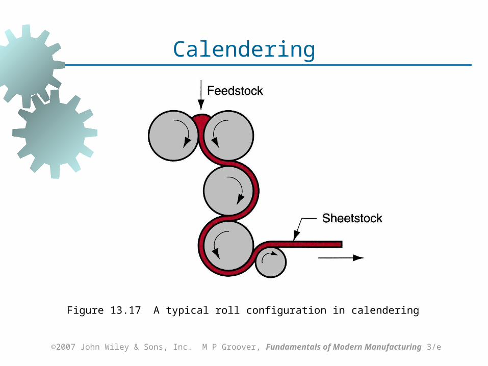
Figure 13.17 A typical roll configuration in calendering
Calendering
Page 38
©2007 John Wiley & Sons, Inc. M P Groover, Fundamentals of Modern Manufacturing 3/e
Fiber and Filament Products
Definitions: Fiber - a long, thin strand whose length is at
least 100 times its cross‑section Filament - a fiber of continuous length
Applications: Fibers and filaments for textiles
Most important application Reinforcing materials in polymer composites
Growing application, but still small compared to textiles
Page 39
©2007 John Wiley & Sons, Inc. M P Groover, Fundamentals of Modern Manufacturing 3/e
Materials for Fibers and Filaments
Fibers can be natural or synthetic Natural fibers constitute ~ 25% of total market
Cotton is by far the most important staple Wool production is significantly less than
cotton Synthetic fibers constitute ~ 75% of total fiber
market Polyester is the most important Others: nylon, acrylics, and rayon
Page 40
©2007 John Wiley & Sons, Inc. M P Groover, Fundamentals of Modern Manufacturing 3/e
Fiber and Filament Production - Spinning
For synthetic fibers, spinning = extrusion of polymer melt or solution through a spinneret, then drawing and winding onto a bobbin
Spinneret = die with multiple small holes The term is a holdover from methods used to
draw and twist natural fibers into yarn or thread
Three variations, depending on polymer :
1. Melt spinning
2. Dry spinning
3. Wet spinning
Page 41
©2007 John Wiley & Sons, Inc. M P Groover, Fundamentals of Modern Manufacturing 3/e
Melt Spinning
Starting polymer is heated to molten state and pumped through spinneret
Typical spinneret is 6 mm (0.25 in) thick and contains approximately 50 holes of diameter 0.25 mm (0.010 in)
Filaments are drawn and air cooled before being spooled onto bobbin
Significant extension and thinning of filaments occur while polymer is still molten, so final diameter wound onto bobbin may be only 1/10 of extruded size
Used for polyester and nylon filaments
Page 42
©2007 John Wiley & Sons, Inc. M P Groover, Fundamentals of Modern Manufacturing 3/e
Figure 13.18 Melt spinning of continuous
filaments
Melt Spinning
Page 43
©2007 John Wiley & Sons, Inc. M P Groover, Fundamentals of Modern Manufacturing 3/e
Dry Spinning
Similar to melt spinning, but starting polymer is in solution and solvent can be separated by evaporation
First step is extrusion through spinneret Extrudate is pulled through a heated chamber
which removes the solvent, leaving the polymer Used for filaments of cellulose acetate and
acrylics
Page 44
©2007 John Wiley & Sons, Inc. M P Groover, Fundamentals of Modern Manufacturing 3/e
Wet Spinning
Similar to melt spinning, but polymer is again in solution, only solvent is non‑volatile
To separate polymer, extrudate is passed through a liquid chemical that coagulates or precipitates the polymer into coherent strands which are then collected onto bobbins
Used to produce filaments of rayon (regenerated cellulose)
Page 45
©2007 John Wiley & Sons, Inc. M P Groover, Fundamentals of Modern Manufacturing 3/e
Subsequent Processing of Filaments
Filaments produced by any of the three processes are usually subjected to further cold drawing to align crystal structure along direction of filament axis Extensions of 2 to 8 are typical Effect is to significantly increase tensile
strength Drawing is done by pulling filament between
two spools, where winding spool is driven at a faster speed than unwinding spool
Page 46
©2007 John Wiley & Sons, Inc. M P Groover, Fundamentals of Modern Manufacturing 3/e
Injection Molding
Polymer is heated to a highly plastic state and forced to flow under high pressure into a mold cavity where it solidifies and the molding is then removed from cavity
Produces discrete components almost always to net shape
Typical cycle time 10 to 30 sec, but cycles of one minute or more are not uncommon
Mold may contain multiple cavities, so multiple moldings are produced each cycle
Page 47
©2007 John Wiley & Sons, Inc. M P Groover, Fundamentals of Modern Manufacturing 3/e
Injection Molded Parts
Complex and intricate shapes are possible Shape limitations:
Capability to fabricate a mold whose cavity is the same geometry as part
Shape must allow for part removal from mold
Part size from 50 g (2 oz) up to 25 kg (more than 50 lb), e.g., automobile bumpers
Injection molding is economical only for large production quantities due to high cost of mold
Page 48
©2007 John Wiley & Sons, Inc. M P Groover, Fundamentals of Modern Manufacturing 3/e
Polymers for Injection Molding
Injection molding is the most widely used molding process for thermoplastics
Some thermosets and elastomers are injection molded Modifications in equipment and operating
parameters must be made to avoid premature cross‑linking of these materials before injection
Page 49
©2007 John Wiley & Sons, Inc. M P Groover, Fundamentals of Modern Manufacturing 3/e
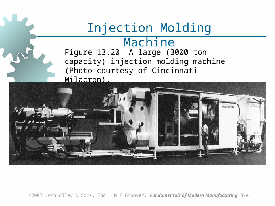
Injection Molding Machine
Two principal components:
1. Injection unit Melts and delivers polymer melt Operates much like an extruder
2. Clamping unit Opens and closes mold each injection
cycle
Page 50
©2007 John Wiley & Sons, Inc. M P Groover, Fundamentals of Modern Manufacturing 3/e
Injection Molding Machine
Figure 13.20 A large (3000 ton capacity) injection molding machine (Photo courtesy of Cincinnati Milacron).
Page 51
©2007 John Wiley & Sons, Inc. M P Groover, Fundamentals of Modern Manufacturing 3/e
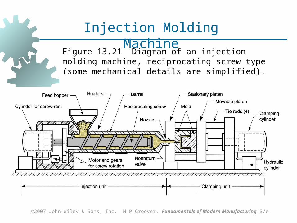
Injection Molding Machine
Figure 13.21 Diagram of an injection molding machine, reciprocating screw type (some mechanical details are simplified).
Page 52
©2007 John Wiley & Sons, Inc. M P Groover, Fundamentals of Modern Manufacturing 3/e
Injection Unit of Molding Machine
Consists of barrel fed from one end by a hopper containing supply of plastic pellets
Inside the barrel is a screw which:
1. Rotates for mixing and heating polymer
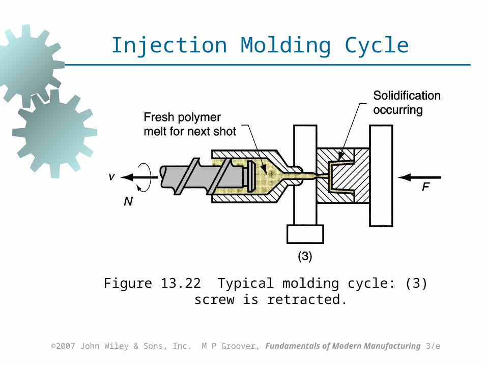
2. Acts as a ram (i.e., plunger) to inject molten plastic into mold Non‑return valve near tip of screw
prevents melt flowing backward along screw threads
Later in molding cycle ram retracts to its former position
Page 53
©2007 John Wiley & Sons, Inc. M P Groover, Fundamentals of Modern Manufacturing 3/e
Clamping Unit of Molding Machine
Functions:
1. Holds two halves of mold in proper alignment with each other
2. Keeps mold closed during injection by applying a clamping force sufficient to resist injection force
3. Opens and closes mold at the appropriate times in molding cycle
Page 54
©2007 John Wiley & Sons, Inc. M P Groover, Fundamentals of Modern Manufacturing 3/e
Figure 13.22 Typical molding cycle: (1) mold is closed
Injection Molding Cycle
Page 55
©2007 John Wiley & Sons, Inc. M P Groover, Fundamentals of Modern Manufacturing 3/e
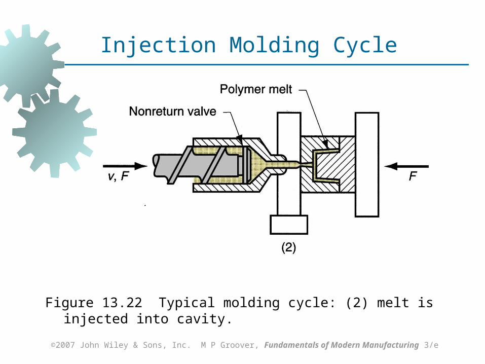
Figure 13.22 Typical molding cycle: (2) melt is injected into cavity.
Injection Molding Cycle
Page 56
©2007 John Wiley & Sons, Inc. M P Groover, Fundamentals of Modern Manufacturing 3/e
Figure 13.22 Typical molding cycle: (3) screw is retracted.
Injection Molding Cycle
Page 57
©2007 John Wiley & Sons, Inc. M P Groover, Fundamentals of Modern Manufacturing 3/e
Figure 13.22 Typical molding cycle: (4) mold opens and part is ejected.
Injection Molding Cycle
Page 58
©2007 John Wiley & Sons, Inc. M P Groover, Fundamentals of Modern Manufacturing 3/e
The Mold
The special tool in injection molding Custom‑designed and fabricated for the part to
be produced When production run is finished, the mold is
replaced with a new mold for the next part Various types of mold for injection molding:
Two-plate mold Three-plate mold Hot-runner mold
Page 59
©2007 John Wiley & Sons, Inc. M P Groover, Fundamentals of Modern Manufacturing 3/e
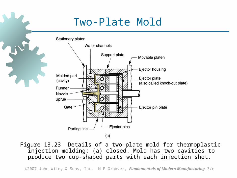
Figure 13.23 Details of a two‑plate mold for thermoplastic injection molding: (a) closed. Mold has two cavities to produce two cup‑shaped parts with each injection shot.
Two-Plate Mold
Page 60
©2007 John Wiley & Sons, Inc. M P Groover, Fundamentals of Modern Manufacturing 3/e
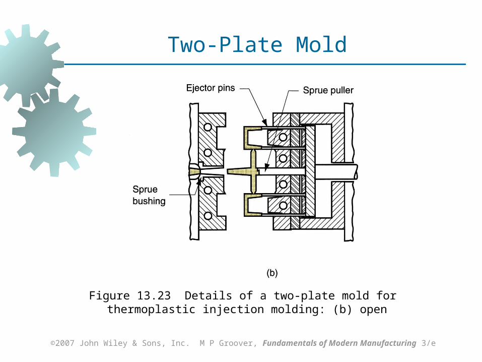
Figure 13.23 Details of a two‑plate mold for thermoplastic injection molding: (b) open
Two-Plate Mold
Page 61
©2007 John Wiley & Sons, Inc. M P Groover, Fundamentals of Modern Manufacturing 3/e
Two‑Plate Mold Features
Cavity – geometry of part but slightly oversized to allow for shrinkage Created by machining of mating surfaces of
two mold halves Distribution channel through which polymer
melt flows from nozzle into mold cavity Sprue - leads from nozzle into mold Runners - lead from sprue to cavity (or
cavities) Gates - constrict flow of plastic into cavity
Page 62
©2007 John Wiley & Sons, Inc. M P Groover, Fundamentals of Modern Manufacturing 3/e
More Two‑Plate Mold Features
Ejection system – to eject molded part from cavity at end of molding cycle Ejector pins built into moving half of mold
usually accomplish this function Cooling system - consists of external pump
connected to passageways in mold, through which water is circulated to remove heat from the hot plastic
Air vents – to permit evacuation of air from cavity as polymer melt rushes in
Page 63
©2007 John Wiley & Sons, Inc. M P Groover, Fundamentals of Modern Manufacturing 3/e
Three‑Plate Mold
Uses three plates to separate parts from sprue and runner when mold opens
Advantages over two-plate mold: As mold opens, runner and parts disconnect
and drop into two containers under mold Allows automatic operation of molding
machine
Page 64
©2007 John Wiley & Sons, Inc. M P Groover, Fundamentals of Modern Manufacturing 3/e
Hot‑Runner Mold
Eliminates solidification of sprue and runner by locating heaters around the corresponding runner channels
While plastic in mold cavity solidifies, material in sprue and runner channels remains molten, ready to be injected into cavity in next cycle
Advantage: Saves material that otherwise would be
scrap in the unit operation
Page 65
©2007 John Wiley & Sons, Inc. M P Groover, Fundamentals of Modern Manufacturing 3/e
Injection Molding Machines
Injection molding machines differ in both injection unit and clamping unit
Name of injection molding machine is based on the type of injection unit used Reciprocating-screw injection molding
machine Plunger-type injection molding machine
Several clamping designs Mechanical (toggle) Hydraulic
Page 66
©2007 John Wiley & Sons, Inc. M P Groover, Fundamentals of Modern Manufacturing 3/e
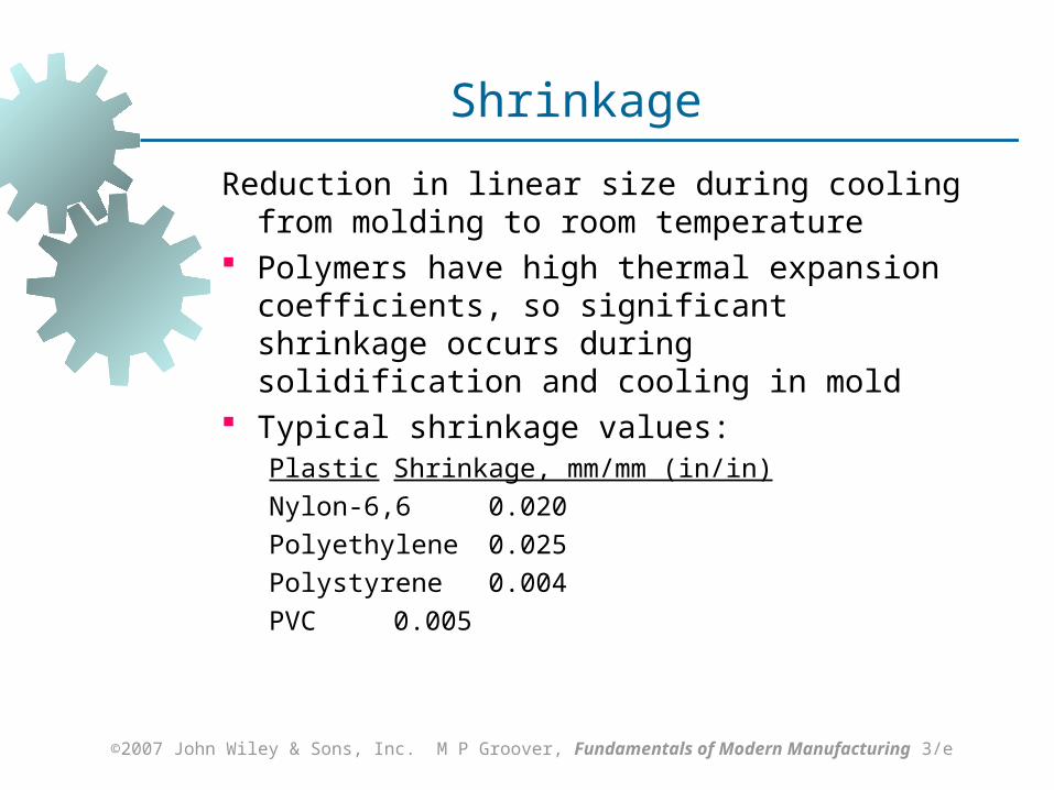
Shrinkage
Reduction in linear size during cooling from molding to room temperature
Polymers have high thermal expansion coefficients, so significant shrinkage occurs during solidification and cooling in mold
Typical shrinkage values: Plastic Shrinkage, mm/mm (in/in)
Nylon‑6,6 0.020
Polyethylene 0.025
Polystyrene 0.004
PVC 0.005
Page 67
©2007 John Wiley & Sons, Inc. M P Groover, Fundamentals of Modern Manufacturing 3/e
Compensation for Shrinkage
Dimensions of mold cavity must be larger than specified part dimensions:
Dc = Dp + DpS + DpS2
where Dc = dimension of cavity; Dp = molded part dimension, and S = shrinkage value Third term on right hand side corrects for
shrinkage in the shrinkage
Page 68
©2007 John Wiley & Sons, Inc. M P Groover, Fundamentals of Modern Manufacturing 3/e
Shrinkage Factors
Fillers in the plastic tend to reduce shrinkage Injection pressure – higher pressures force
more material into mold cavity to reduce shrinkage
Compaction time - similar effect – longer time forces more material into cavity to reduce shrinkage
Molding temperature - higher temperatures lower polymer melt viscosity, allowing more material to be packed into mold to reduce shrinkage
Page 69
©2007 John Wiley & Sons, Inc. M P Groover, Fundamentals of Modern Manufacturing 3/e
Thermoplastic Foam Injection Molding
Molding of thermoplastic parts that possess dense outer skin surrounding lightweight foam center
Part has high stiffness‑to‑weight ratio suited to structural applications
Produced either by introducing a gas into molten plastic in injection unit or by mixing a gas‑producing ingredient with starting pellets
A small amount of melt is injected into mold cavity, where it expands to fill cavity
Foam in contact with cold mold surface collapses to form dense skin, while core retains cellular structure
Page 70
©2007 John Wiley & Sons, Inc. M P Groover, Fundamentals of Modern Manufacturing 3/e
Injection Molding of Thermosets
Equipment and operating procedure must be modified to avoid premature cross‑linking of TS polymer Reciprocating‑screw injection unit with
shorter barrel length Temperatures in barrel are relatively low Melt is injected into a heated mold, where
cross‑linking occurs to cure the plastic Curing in the mold is the most
time‑consuming step in the cycle Mold is then opened and part is removed
Page 71
©2007 John Wiley & Sons, Inc. M P Groover, Fundamentals of Modern Manufacturing 3/e
Reaction Injection Molding
Two highly reactive liquid ingredients are mixed and immediately injected into a mold cavity where chemical reactions leading to solidification occur
RIM was developed with polyurethane to produce large automotive parts such as bumpers and fenders RIM polyurethane parts possess a foam
internal structure surrounded by a dense outer skin
Other materials used in RIM: epoxies, and urea‑formaldehyde
Page 72
©2007 John Wiley & Sons, Inc. M P Groover, Fundamentals of Modern Manufacturing 3/e
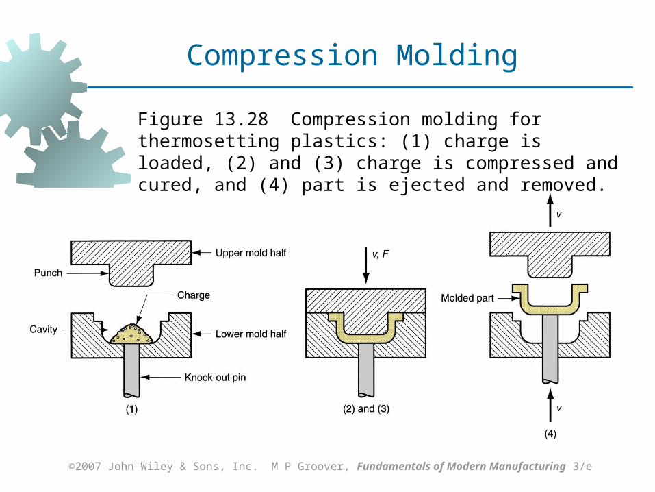
Compression Molding
A widely used molding process for thermosetting plastics
Also used for rubber tires and polymer matrix composite parts
Molding compound available in several forms: powders or pellets, liquid, or preform
Amount of charge must be precisely controlled to obtain repeatable consistency in the molded product
Page 73
©2007 John Wiley & Sons, Inc. M P Groover, Fundamentals of Modern Manufacturing 3/e
Compression Molding
Figure 13.28 Compression molding for thermosetting plastics: (1) charge is loaded, (2) and (3) charge is compressed and cured, and (4) part is ejected and removed.
Page 74
©2007 John Wiley & Sons, Inc. M P Groover, Fundamentals of Modern Manufacturing 3/e
Molds for Compression Molding
Simpler than injection molds No sprue and runner system in a compression
mold Process itself generally limited to simpler part
geometries due to lower flow capabilities of TS materials
Mold must be heated, usually by electric resistance, steam, or hot oil circulation
Page 75
©2007 John Wiley & Sons, Inc. M P Groover, Fundamentals of Modern Manufacturing 3/e
Compression Molding
Molding materials: Phenolics, melamine, urea‑formaldehyde,
epoxies, urethanes, and elastomers Typical compression-molded products:
Electric plugs, sockets, and housings; pot handles, and dinnerware plates
Page 76
©2007 John Wiley & Sons, Inc. M P Groover, Fundamentals of Modern Manufacturing 3/e
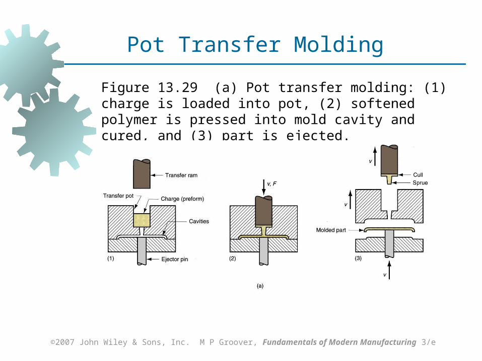
Transfer Molding
TS charge is loaded into a chamber immediately ahead of mold cavity, where it is heated; pressure is then applied to force soft polymer to flow into heated mold where it cures
Two variants: Pot transfer molding - charge is injected
from a "pot" through a vertical sprue channel into cavity
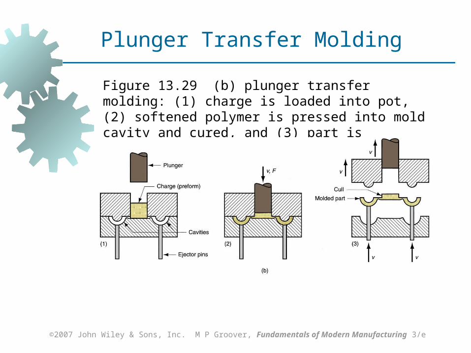
Plunger transfer molding – plunger injects charge from a heated well through channels into cavity
Page 77
©2007 John Wiley & Sons, Inc. M P Groover, Fundamentals of Modern Manufacturing 3/e
Figure 13.29 (a) Pot transfer molding: (1) charge is loaded into pot, (2) softened polymer is pressed into mold cavity and cured, and (3) part is ejected.
Pot Transfer Molding
Page 78
©2007 John Wiley & Sons, Inc. M P Groover, Fundamentals of Modern Manufacturing 3/e
Figure 13.29 (b) plunger transfer molding: (1) charge is loaded into pot, (2) softened polymer is pressed into mold cavity and cured, and (3) part is ejected.
Plunger Transfer Molding
Page 79
©2007 John Wiley & Sons, Inc. M P Groover, Fundamentals of Modern Manufacturing 3/e
Compression vs. Transfer Molding
In both processes, scrap is produced each cycle as leftover material, called the cull
The TS scrap cannot be recovered Transfer molding is capable of molding more
intricate part shapes than compression molding but not as intricate as injection molding
Transfer molding lends itself to molding with inserts, in which a metal or ceramic insert is placed into cavity prior to injection, and the plastic bonds to insert during molding
Page 80
©2007 John Wiley & Sons, Inc. M P Groover, Fundamentals of Modern Manufacturing 3/e
Blow Molding
Molding process in which air pressure is used to inflate soft plastic into a mold cavity
Important for making one‑piece hollow plastic parts with thin walls, such as bottles
Because these items are used for consumer beverages in mass markets, production is typically organized for very high quantities
Page 81
©2007 John Wiley & Sons, Inc. M P Groover, Fundamentals of Modern Manufacturing 3/e
Blow Molding Process
Accomplished in two steps:
1. Fabrication of a starting tube, called a parison
2. Inflation of the tube to desired final shape Forming the parison is accomplished by either
Extrusion or Injection molding
Page 82
©2007 John Wiley & Sons, Inc. M P Groover, Fundamentals of Modern Manufacturing 3/e
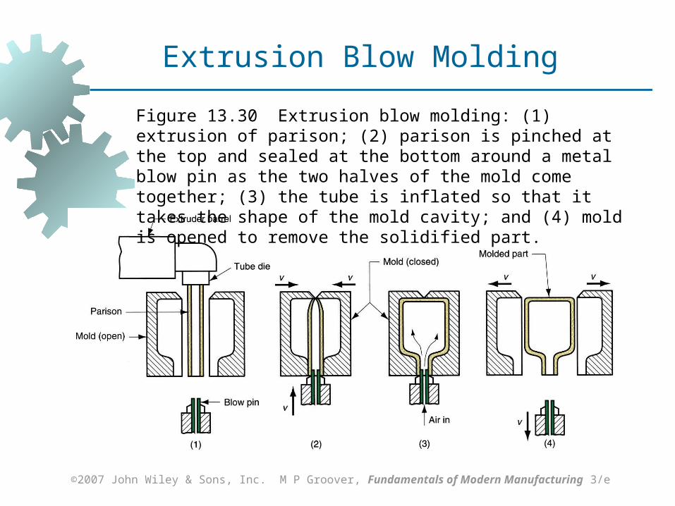
Figure 13.30 Extrusion blow molding: (1) extrusion of parison; (2) parison is pinched at the top and sealed at the bottom around a metal blow pin as the two halves of the mold come together; (3) the tube is inflated so that it takes the shape of the mold cavity; and (4) mold is opened to remove the solidified part.
Extrusion Blow Molding
Page 83
©2007 John Wiley & Sons, Inc. M P Groover, Fundamentals of Modern Manufacturing 3/e
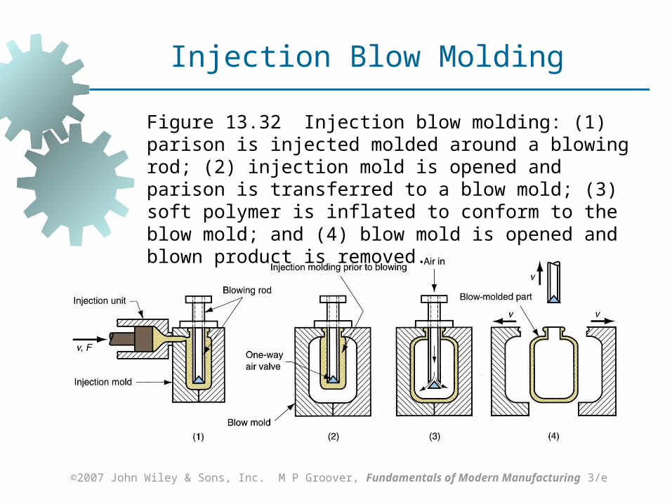
Figure 13.32 Injection blow molding: (1) parison is injected molded around a blowing rod; (2) injection mold is opened and parison is transferred to a blow mold; (3) soft polymer is inflated to conform to the blow mold; and (4) blow mold is opened and blown product is removed.
Injection Blow Molding
Page 84
©2007 John Wiley & Sons, Inc. M P Groover, Fundamentals of Modern Manufacturing 3/e
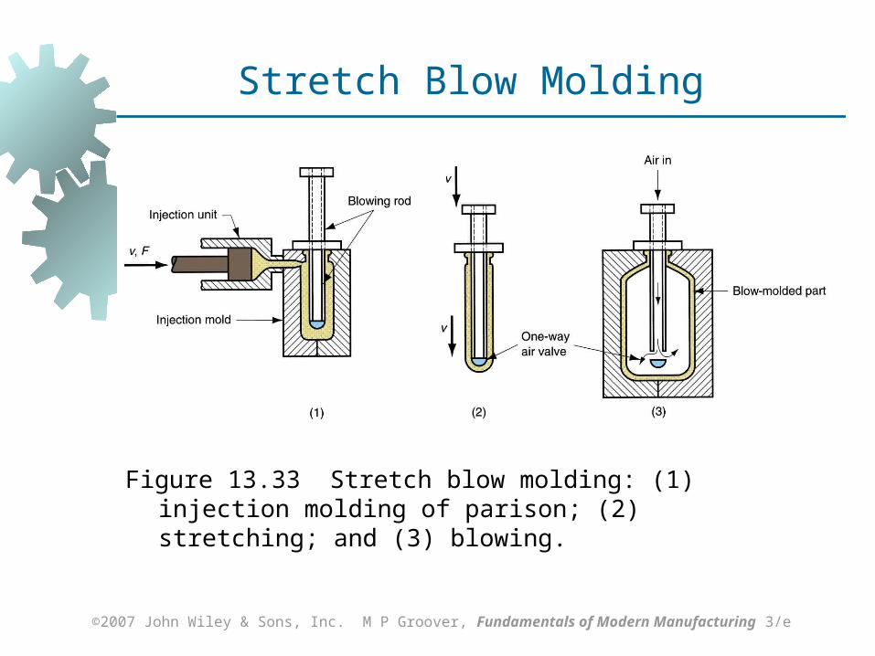
Stretch Blow Molding
Variation of injection blow molding in which blowing rod stretches the soft parison for a more favorable stressing of polymer than conventional blow molding
Resulting structure is more rigid, more transparent, and more impact resistant
Most widely used material is polyethylene terephthalate (PET) which has very low permeability and is strengthened by stretch blow molding Combination of properties makes it ideal as
container for carbonated beverages
Page 85
©2007 John Wiley & Sons, Inc. M P Groover, Fundamentals of Modern Manufacturing 3/e
Figure 13.33 Stretch blow molding: (1) injection molding of parison; (2) stretching; and (3) blowing.
Stretch Blow Molding
Page 86
©2007 John Wiley & Sons, Inc. M P Groover, Fundamentals of Modern Manufacturing 3/e
Materials and Products in Blow Molding
Blow molding is limited to thermoplastics Materials: high density polyethylene,
polypropylene (PP), polyvinylchloride (PVC), and polyethylene terephthalate
Products: disposable containers for beverages and other liquid consumer goods, large shipping drums (55 gallon) for liquids and powders, large storage tanks (2000 gallon), gasoline tanks, toys, and hulls for sail boards and small boats
Page 87
©2007 John Wiley & Sons, Inc. M P Groover, Fundamentals of Modern Manufacturing 3/e
Thermoforming
Flat thermoplastic sheet or film is heated and deformed into desired shape using a mold
Heating usually accomplished by radiant electric heaters located on one or both sides of starting plastic sheet or film
Widely used in packaging of products and to fabricate large items such as bathtubs, contoured skylights, and internal door liners for refrigerators
Page 88
©2007 John Wiley & Sons, Inc. M P Groover, Fundamentals of Modern Manufacturing 3/e
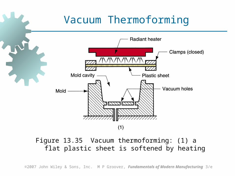
Figure 13.35 Vacuum thermoforming: (1) a flat plastic sheet is softened by heating
Vacuum Thermoforming
Page 89
©2007 John Wiley & Sons, Inc. M P Groover, Fundamentals of Modern Manufacturing 3/e
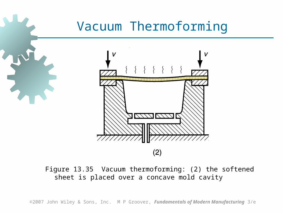
Figure 13.35 Vacuum thermoforming: (2) the softened sheet is placed over a concave mold cavity
Vacuum Thermoforming
Page 90
©2007 John Wiley & Sons, Inc. M P Groover, Fundamentals of Modern Manufacturing 3/e
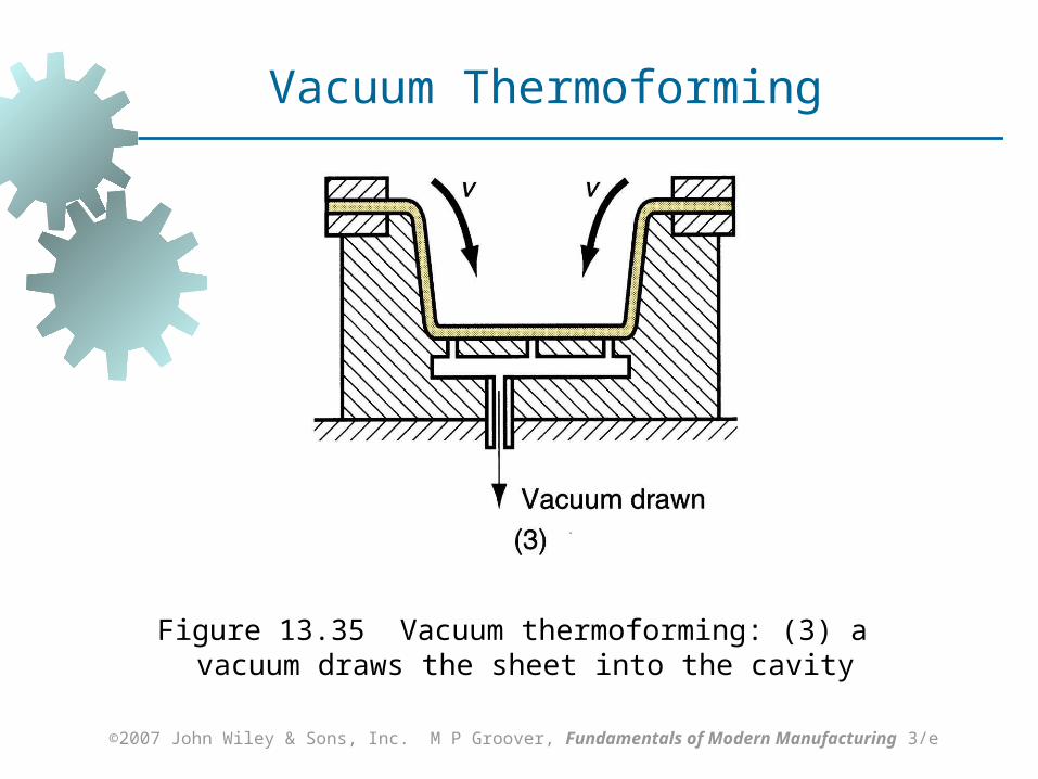
Figure 13.35 Vacuum thermoforming: (3) a vacuum draws the sheet into the cavity
Vacuum Thermoforming
Page 91
©2007 John Wiley & Sons, Inc. M P Groover, Fundamentals of Modern Manufacturing 3/e
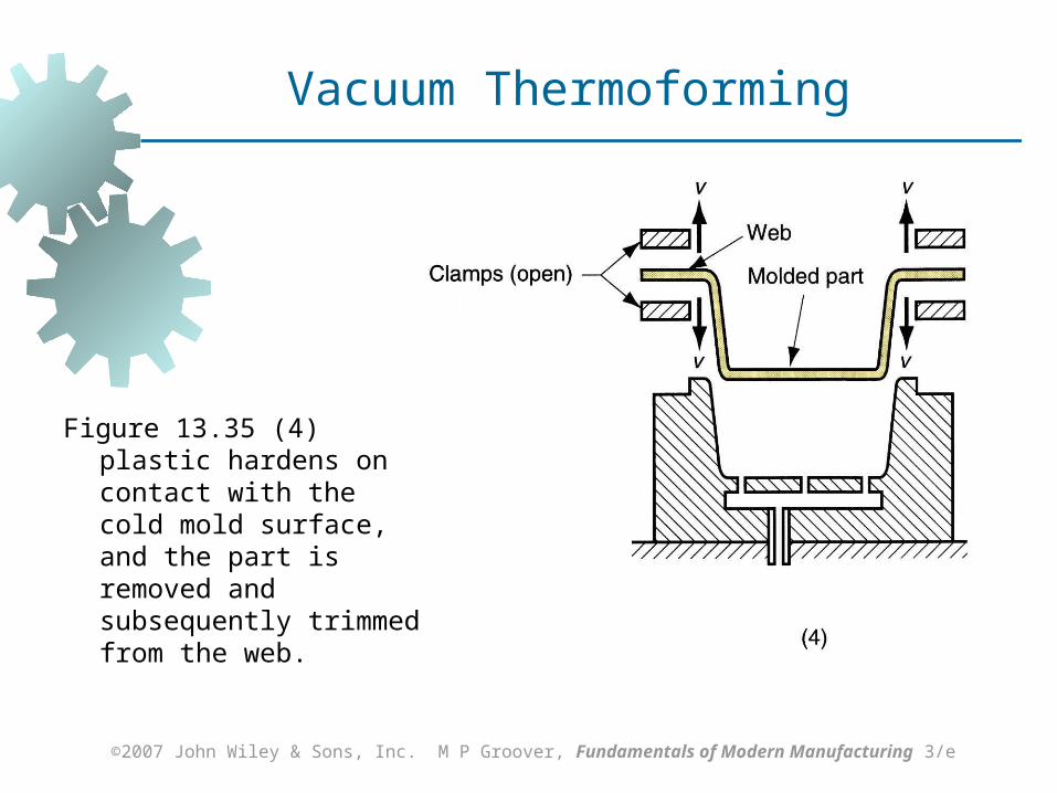
Figure 13.35 (4) plastic hardens on contact with the cold mold surface, and the part is removed and subsequently trimmed from the web.
Vacuum Thermoforming
Page 92
©2007 John Wiley & Sons, Inc. M P Groover, Fundamentals of Modern Manufacturing 3/e
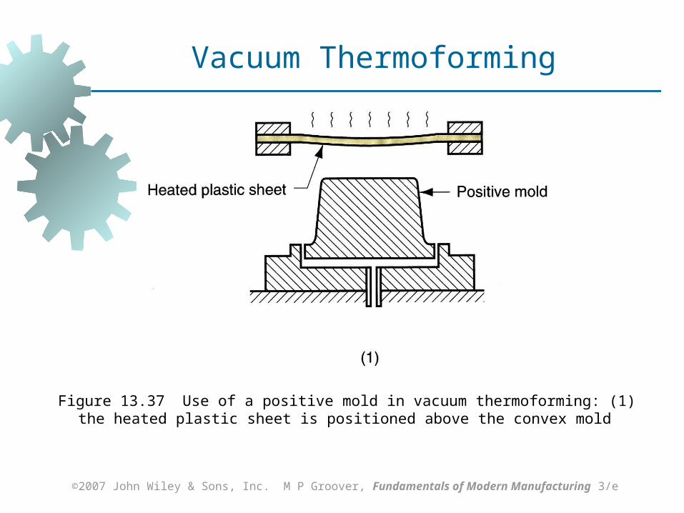
Negative Molds vs. Positive Molds
Negative mold has concave cavity
Positive mold has convex shape Both types are used in thermoforming For positive mold, heated sheet is draped over
convex form and negative or positive pressure forces plastic against mold surface
Page 93
©2007 John Wiley & Sons, Inc. M P Groover, Fundamentals of Modern Manufacturing 3/e
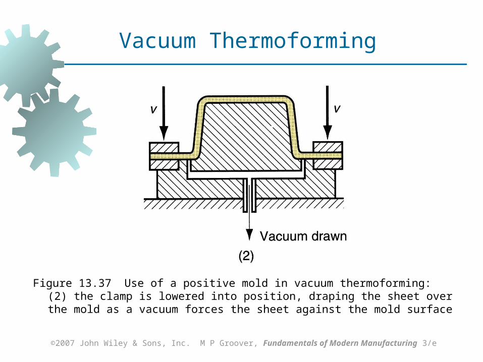
Figure 13.37 Use of a positive mold in vacuum thermoforming: (1) the heated plastic sheet is positioned above the convex mold
Vacuum Thermoforming
Page 94
©2007 John Wiley & Sons, Inc. M P Groover, Fundamentals of Modern Manufacturing 3/e
Figure 13.37 Use of a positive mold in vacuum thermoforming: (2) the clamp is lowered into position, draping the sheet over the mold as a vacuum forces the sheet against the mold surface
Vacuum Thermoforming
Page 95
©2007 John Wiley & Sons, Inc. M P Groover, Fundamentals of Modern Manufacturing 3/e
Materials for Thermoforming
Only thermoplastics can be thermoformed, Extruded sheets of thermosetting or
elastomeric polymers have already been cross‑linked and cannot be softened by reheating
Common TP polymers: polystyrene, cellulose acetate, cellulose acetate butyrate, ABS, PVC, acrylic (polymethylmethacrylate), polyethylene, and polypropylene
Page 96
©2007 John Wiley & Sons, Inc. M P Groover, Fundamentals of Modern Manufacturing 3/e
Applications of Thermoforming
Thin films: blister packs and skin packs for packaging commodity products such as cosmetics, toiletries, small tools, and fasteners (nails, screws, etc.) For best efficiency, filling process to
containerize item(s) is immediately downstream from thermoforming
Thicker sheet stock: boat hulls, shower stalls, advertising displays and signs, bathtubs, certain toys, contoured skylights, internal door liners for refrigerators
Page 97
©2007 John Wiley & Sons, Inc. M P Groover, Fundamentals of Modern Manufacturing 3/e
Casting
Pouring liquid resin into a mold, using gravity to fill cavity, where polymer hardens
Both thermoplastics and thermosets are cast Thermoplastics: acrylics, polystyrene,
polyamides (nylons) and PVC Thermosetting polymers: polyurethane,
unsaturated polyesters, phenolics, and epoxies
Simpler mold Suited to low quantities
Page 98
©2007 John Wiley & Sons, Inc. M P Groover, Fundamentals of Modern Manufacturing 3/e
Polymer Foam
A polymer‑and‑gas mixture that gives the material a porous or cellular structure
Most common polymer foams: polystyrene (Styrofoam, a trademark), polyurethane
Other polymers: natural rubber ("foamed rubber") and polyvinylchloride (PVC)
Page 99
©2007 John Wiley & Sons, Inc. M P Groover, Fundamentals of Modern Manufacturing 3/e
Properties of a Foamed Polymer
Low density High strength per unit weight Good thermal insulation Good energy absorbing qualities
Page 100
©2007 John Wiley & Sons, Inc. M P Groover, Fundamentals of Modern Manufacturing 3/e
Classification of Polymer Foams
Elastomeric - matrix polymer is a rubber, capable of large elastic deformation
Flexible - matrix is a highly plasticized polymer such as soft PVC
Rigid - polymer is a stiff thermoplastic such as polystyrene or a thermoset such as a phenolic
Page 101
©2007 John Wiley & Sons, Inc. M P Groover, Fundamentals of Modern Manufacturing 3/e
Applications of Polymer Foams
Characteristic properties of polymer foams, and the ability to control elastic behavior by selection of base polymer, make these materials suitable for certain applications
Applications: hot beverage cups, heat insulating structural materials, cores for structural panels, packaging materials, cushion materials for furniture and bedding, padding for automobile dashboards, and products requiring buoyancy
Page 102
©2007 John Wiley & Sons, Inc. M P Groover, Fundamentals of Modern Manufacturing 3/e
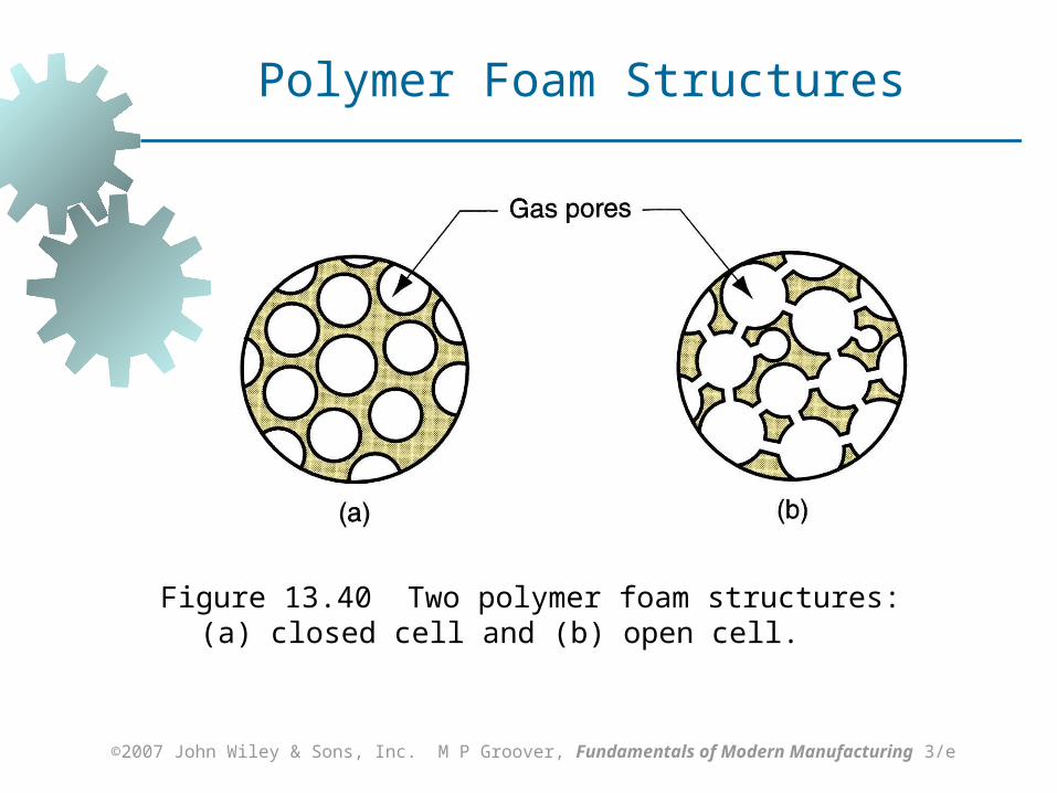
Figure 13.40 Two polymer foam structures: (a) closed cell and (b) open cell.
Polymer Foam Structures
Page 103
©2007 John Wiley & Sons, Inc. M P Groover, Fundamentals of Modern Manufacturing 3/e
Extrusion of Polystyrene Foams
Polystyrene (PS) is a thermoplastic polymer A physical or chemical blowing agent is fed
into polymer melt near die end of extruder barrel; thus, extrudate consists of expanded polymer
Products: large sheets and boards that are subsequently cut to size for heat insulation panels and sections
Page 104
©2007 John Wiley & Sons, Inc. M P Groover, Fundamentals of Modern Manufacturing 3/e
Molding Processes for PS Foams
Expandable foam molding Molding material consists of prefoamed
polystyrene beads Beads are fed into mold cavity where they
are further expanded and fused together to form the molded product
Products: hot beverage cups
Page 105
©2007 John Wiley & Sons, Inc. M P Groover, Fundamentals of Modern Manufacturing 3/e
Shaping of Polyurethane Foams
Polyurethane can be thermosetting, elastomer or thermoplastic (less common)
Polyurethane foam products are made in a one‑step process in which the two liquid ingredients are mixed and immediately fed into a mold or other form Polymer is synthesized and part
geometry is created at the same time Shaping processes for polyurethane foam:
Spraying Pouring
Page 106
©2007 John Wiley & Sons, Inc. M P Groover, Fundamentals of Modern Manufacturing 3/e
Product Design Guidelines: General
Strength and stiffness Plastics are not as strong or stiff as metals Avoid applications where high stresses will
be encountered Creep resistance is also a limitation Strength‑to‑weight ratios for some plastics
are competitive with metals in certain applications
Page 107
©2007 John Wiley & Sons, Inc. M P Groover, Fundamentals of Modern Manufacturing 3/e
Product Design Guidelines: General
Impact Resistance Capacity of plastics to absorb impact is
generally good; plastics compare favorably with most metals
Service temperatures Limited relative to metals and ceramics
Thermal expansion Dimensional changes due to temperature
changes much more significant than for metals
Page 108
©2007 John Wiley & Sons, Inc. M P Groover, Fundamentals of Modern Manufacturing 3/e
Product Design Guidelines: General
Many plastics are subject to degradation from sunlight and other forms of radiation
Some plastics degrade in oxygen and ozone atmospheres
Plastics are soluble in many common solvents Plastics are resistant to conventional corrosion
mechanisms that afflict many metals
Page 109
©2007 John Wiley & Sons, Inc. M P Groover, Fundamentals of Modern Manufacturing 3/e
Product Design Guidelines: Extrusion
Wall thickness Uniform wall thickness is desirable in an
extruded cross section Variations in wall thickness result in non-
uniform plastic flow and uneven cooling which tend to warp extrudate
Page 110
©2007 John Wiley & Sons, Inc. M P Groover, Fundamentals of Modern Manufacturing 3/e
Product Design Guidelines: Extrusion
Hollow sections Hollow sections complicate die design and
plastic flow Desirable to use extruded cross‑sections
that are not hollow yet satisfy functional requirements
Page 111
©2007 John Wiley & Sons, Inc. M P Groover, Fundamentals of Modern Manufacturing 3/e
Product Design Guidelines: Extrusion
Corners Sharp corners, inside and outside, should
be avoided in extruded cross sections They result in uneven flow during
processing and stress concentrations in the final product
Page 112
©2007 John Wiley & Sons, Inc. M P Groover, Fundamentals of Modern Manufacturing 3/e
Product Design Guidelines: Moldings
Economic production quantities Each part requires a unique mold, and the
mold for any molding process can be costly, particularly for injection molding
Minimum production quantities for injection molding are usually around 10,000 pieces
For compression molding, minimum quantities are 1000 parts, due to simpler mold designs
Transfer molding lies between injection molding and compression molding
Page 113
©2007 John Wiley & Sons, Inc. M P Groover, Fundamentals of Modern Manufacturing 3/e
Product Design Guidelines: Moldings
Part complexity An advantage of plastic molding is that it
allows multiple functional features to be combined into one part
Although more complex part geometries mean more costly molds, it may nevertheless be economical to design a complex molding if the alternative involves many individual components that must be assembled
Page 114
©2007 John Wiley & Sons, Inc. M P Groover, Fundamentals of Modern Manufacturing 3/e
Product Design Guidelines: Moldings
Wall thickness Thick cross sections are wasteful of
material, more likely to cause warping due to shrinkage, and take longer to harden
Reinforcing ribs Achieves increased stiffness without
excessive wall thickness Ribs should be made thinner than the walls
they reinforce to minimize sink marks on outside wall
Page 115
©2007 John Wiley & Sons, Inc. M P Groover, Fundamentals of Modern Manufacturing 3/e
Product Design Guidelines: Moldings
Corner radii and fillets Sharp corners, both external and internal,
are undesirable in molded parts They interrupt smooth flow of the melt, tend
to create surface defects, and cause stress concentrations in the part
Holes Holes are quite feasible in plastic moldings,
but they complicate mold design and part removal
Page 116
©2007 John Wiley & Sons, Inc. M P Groover, Fundamentals of Modern Manufacturing 3/e
Product Design Guidelines: Moldings
Draft A molded part should be designed with a
draft on its sides to facilitate removal from mold
Especially important on inside wall of a cup‑shaped part because plastic contracts against positive mold shape
Recommended draft: For thermosets, ~ 1/2 to 1 For thermoplastics, ~ 1/8 to 1/2
Page 117
©2007 John Wiley & Sons, Inc. M P Groover, Fundamentals of Modern Manufacturing 3/e
Product Design Guidelines: Moldings
Tolerances Although shrinkage is predictable under
closely controlled conditions, generous tolerances are desirable for injection moldings because of
Variations in process parameters that affect shrinkage
Diversity of part geometries encountered