EVALUATION OF RUSINEK-KLAPACZKO MODEL FOR HIGH STRAIN RATE RESPONSE OF STEEL SHEETS SHARIFAH NUR’AI SHIKIN BT SYED NOH A thesis submitted in fulfilment of the requirements for the award of the degree of Master of Engineering (Mechanical) Faculty of Mechanical Engineering Universiti Teknologi Malaysia JULY 2013
Transcript
EVALUATION OF RUSINEK-KLAPACZKO MODEL FOR HIGH STRAIN
RATE RESPONSE OF STEEL SHEETS
SHARIFAH NUR’AI SHIKIN BT SYED NOH
A thesis submitted in fulfilment of the
requirements for the award of the degree of
Master of Engineering (Mechanical)
Faculty of Mechanical Engineering
Universiti Teknologi Malaysia
JULY 2013
iii
To my beloved father and mother
iv
ACKNOWLEDGEMENT
First and foremost, I would like to express my heartfelt appreciation to my
respectful supervisors, Prof. Dr. Mohd. Nasir Tamin and Dr. Nazri Kamsah for
providing me with an opportunity to pursue my studies here in the Computational
Solid Mechanics Laboratory (CSMLab), Faculty of Mechanical Engineering,
Universiti Teknologi Malaysia (UTM). They have spared their precious time for me
and guided me with their knowledge and experiences diligently. Without their
outstanding academic and industrial supports, the completion of my project would
not be possible. It has been a pleasure working under his guidance. His support,
encouragement and patience have proved invaluable in the completion of this work.
I would like to extend my gratitude to all CSMLab members especially
Technofund Group members who have provided me with valuable suggestions and
recommendations. To all CSMLab members, thank you for the provided assistance at
various occasions throughout my study. Their views and tips are useful indeed.
Unfortunately, it is not possible to list all of them in this limited space.
Last but not least, I would extend my sincere appreciation to my beloved
parents, Syed Noh b. Syed Abdullah and Sumirah bt. Suparman for their continuous
supports and encouragements throughout these years. I am greatly indebted to them
for their infinite love and confidence towards me. My special gratitude are due to my
younger sister, Sharifah Aneesa bt. Syed Noh, Zainalariffin b. Mohd Hussin, my
friends and co-worker who involved directly and indirectly for their understanding
and support in completing this thesis. Without their encouragement, helps and
understandings it would have been impossible for me to finish this thesis.
v
ABSTRACT
Automotive steel sheet structures are likely to experience high strain-rate
loading during impact and crash conditions. A quasi-static stress-strain at low strain
rate data alone may not give an accurate numerical prediction of sheet metal structure
behaviour at high strain rates. In this study, the response of sheet metal which is low
carbon steel with 0.045 C (wt %) and high strength steel, DP600 subjected to high
strain rates loading is investigated. The Rusinek-Klapaczko (R-K) constitutive model
is employed to predict the material behaviour at varying strain rates because the
model incorporates strain, strain rates and temperature evaluation terms. In order to
characterize the response of sheet metal at high strain rates, tensile experiments using
an Instron machine were carried out at strain rates between 0.001 s-1
until 0.1 s-1
as a
quasi-static rates and together with published high strain rate data up to the range of
500 s-1
was employed. These true stress-strain curves are used to extract the
parameters of the R-K model. The R-K model predictive capability is then assessed
by simulating a tensile test using finite element method (FEM). It was found that the
R-K model is able to predict the tensile behaviour of the materials with an error of
about 5 %. The validated R-K model was then incorporated into a FE simulation of
bending of thin-walled tube made of low carbon steel and the results were compared
with the experimental observation. It was found that the deformation of the structure
has a good agreement with the experimental observation. The R-K model was also
able to adequately capture the variation of the plastic strain rate in the structure.
vi
ABSTRAK
Struktur kepingan besi automotif kebiasaannya akan mengalami terikan
berkadar tinggi ketika hentaman dan perlanggaran. Data tegasan-terikan kuasi-statik
pada kadar terikan yang rendah semata-mata tidak dapat memberikan ramalan
berangka yang tepat tentang kelakuan struktur kepingan besi pada kadar terikan yang
tinggi. Di dalam kajian ini, tindak balas kepingan keluli iaitu keluli karbon rendah
dengan kandungan karbon 0.045 C (wt %) dan keluli berkekuatan tinggi, DP600
terhadap bebanan terikan tinggi akan dikaji. Model Rusinek-Klapaczko (R-K)
digunakan untuk meramal kelakuan kepingan besi pada terikan yang berbeza-beza
kerana model ini menggabungkan terikan, kadar keterikan dan taksiran suhu. Untuk
mencirikan tindak balas kepingan kaluli pada terikan berkadar tinggi, eksperimen
tegasan menggunakan mesin Instron telah di jalankan pada kadar 0.001 s-1
sehingga
0.1 s-1
untuk terikan berkadar rendah dan bersama-sama data berterikan tinggi yang
telah sedia ada sehingga lingkungan kadar 500 s-1
telah digunakan. Graf tegasan-
terikan ini digunakan untuk mendapatkan parameter-parameter bagi model R-K.
Kebolehan meramal oleh model R-K dinilai dengan mensimulasi ujian tegangan
menggunakan kaedah unsur terhingga. Didapati bahawa model R-K boleh
meramalkan tingkah laku tegangan bahan dengan ralat sebanyak 5 %. Model R-K yg
telah disahkan kemudian digabungkan ke dalam simulasi lenturan tiub berdinding
nipis diperbuat daripada keluli karbon rendah dan keputusan yang diperolehi
dibandingkan dengan eksperimen. Keputusan menunjukkan bahawa ubah bentuk
struktur mempunyai persetujuan yang baik dengan eksperimen. Model R-K juga
berkebolehan untuk menangkap variasi terikan plastik di dalam struktur dengan
memadai.
vii
TABLE OF CONTENTS
CHAPTER
TITLE PAGE
DECLARATION
DEDICATION
ACKNOWLEDGEMENTS
ABSTRACT
ABSTRAK
TABLE OF CONTENTS
LIST OF TABLES
LIST OF FIGURES
LIST OF ABBREVIATIONS
LIST OF SYMBOLS
LIST OF APPENDICES
ii
iii
iv
v
vi
vii
x
xi
xiv
xv
xviii
1 INTRODUCTION
1.1 Background of Study
1.2 Overview
1.3 Problem Statement
1.4 Objectives
1.5 Scope of Study
1
1
2
4
5
5
2 LITERATURE REVIEW
2.1 Stress-Strain Response of Metals
2.2 Behavior of Materials at High Strain Rates
2.3 Metallurgy of Steel
7
7
11
14
viii
2.3.1 Carbon Steel
2.3.2 High Strength Steel
2.3.3 Fracture Modes
2.4 Overview of Constitutive Model
2.4.1 The Johnson-Cook Model
2.4.2 The Zerilli-Armstrong Model
2.4.3 The Rusinek-Klepaczko Model
2.5 Rusinek-Klepaczko Material Model
2.5.1 Characteristic of R-K Model
15
18
21
24
26
27
30
30
34
3 RESEARCH METHODOLOGY
3.1 Research Framework
3.2 Metallurgical Study
3.2.1 Materials and Chemical Composition
3.2.2 Microstructures
3.2.3 Hardness
3.3 Tension Tests
3.3.1 Fractographic Analysis
3.3.2 Determination of Rusinek-Klepaczko Model
Parameters
3.4 Bending Test on Thin-Walled Tube
3.4 1 Instrumented Thin-Walled Tube Specimen
3.4 2 Test Set-up and Procedures
3.5 Finite Element Simulations
3.5.1 Tension Test Model Geometry
3.5.2 Thin-Walled Tube Model Geometry
3.5.3 Material Model Subroutine
40
40
42
42
43
44
45
46
47
50
51
52
54
54
56
59
RESULTS & DISCUSSION
4.1 Properties and Behaviour of Steel Sheet Material
4.1.1 Chemical composition
4.1.2 Microstructures
4.1.3 Hardness
61
61
61
62
64
ix
4.1.4 Stress-Strain Curves
4.1.5 Effect of Strain Rates Tensile Behaviour
4.1.6 Fracture Modes
4.1.7 Rusinek-Klepaczko Model Parameters
4.1.8 Validated Rusinek-Klepaczko Model for
Uniaxial Response
4.2 Flexural Response of Thin-Walled Tube
4.2.1 Chemical Composition and Microstructures
4.2.2 Stress-Strain Curves
4.2.3 Determination of Rusinek-Klepaczko Model
Parameters
4.2.4 Deformation Under Three-Point Bending
4.2.5 Stress and Distribution
65
67
72
73
77
82
83
84
85
88
94
5 CONCLUSIONS & RECOMMENDATIONS
5.1 Conclusions
5.2 Recommendations
96
96
97
REFERENCES
99
APPENDIX A-B 103
x
LIST OF TABLES
TABLE NO.
TITLE PAGE
2.1
2.2
2.3
2.4
2.5
3.1
4.1
4.2
4.3
4.4
4.5
R-O model parameters for low carbon steel
J-C model parameters for DDQ
Z-A model parameters for DDQ
Descriptions of R-K model parameters
R-K model parameters for mild steel ES
Material constant of R-K require to determine
Chemical composition of the LCS and DP600 (% of wt)
Mechanical properties for LCS and DP600 at different
strain rates
R-K model parameters for LCS and DP600
Chemical composition of thin-walled tube
R-K parameters for thin-walled tube
25
28
28
34
39
48
62
70
75
83
87
xi
LIST OF FIGURES
FIGURE NO.
TITLE PAGE
2.1
2.2
2.3
2.4
2.5
2.6
2.7
2.8
2.9
2.10
Tension test data obtained from the current study of low
carbon steel
Comparison between engineering stress-strain curve and
true stress-strain curve of low carbon steel obtained from
the current study
Strain rate effects on (a) low carbon steel (b) DP600 at
room temperature
Temperature effects on flow stress for mild steel ES at1s-1
Schematic diagram of strain rate regimes (in reciprocal
seconds) and the techniques that have been developed for
obtaining them
Iron Carbon Diagram
Photomicrographs of α-ferrite
Optical micrograph of low carbon steel sheet (AISI 1010)
in annealed condition
Optical micrographs of DP600
Transmission electron microscope image of the ferrite-
martensite interface in a dual phase steel and the
corresponding stress-strain curve which shows the effect
of the volume percent of martensite
9
11
13
14
14
17
17
18
20
20
xii
2.11
2.12
2.13
2.14
2.15
2.16
2.17
2.18
2.19
2.20
2.21
3.1
3.2
3.3
3.4
3.5
Stage in the cup and cone fracture (a) Initial necking (b)
Small cavity formation (c) Coalescence of cavities to
form a crack (d) Crack propagation (e) Final shear
fracture
Spherical dimples characteristic of ductile fracture
resulting from uniaxial tensile loads
Characteristic of brittle fracture (a) V-shaped “chevron”
marking (b) radial fan-shaped ridges
Micrographs of the tensile fracture surface of the low
carbon steel sheet (AISI 1010)
Fracture surface of DP600 under tensile test
Predicted stress-strain R-O model with experimental data
obtained from the current study of LCS at 0.001667s-1
DDQ sheet ambient temperature results fit with the (a)
Johnson-Cook model (b) Zerilli-Armstrong constitutive
model
Evolution of Young’s modulus ratio for different θ*
values
Evolution of Young’s modulus ratio of different steels
with temperature
(a) effect of the hardening exponent n(έp,T) on the
internal stress σμ during plastic deformation, and
definition of the upper limit of n(έp,T) and (b) Effect of
strain rate on the effective stress with temperature
Comparison between R-K constitutive model predictions
and numerical simulations using the modelling proposed
for two strain rates
Operational research framework
GDS machine
Specimen for microstructure test
Vickers hardness machine
Geometry size of tensile test specimen follows by
E8/E8M standard (ASTM)
22
22
23
23
23
25
29
32
35
37
38
41
43
44
45
46
xiii
3.6
3.7
3.8
3.9
3.10
3.11
3.12
3.13
3.14
3.15
3.16
3.17
4.1
4.2
4.3
4.4
4.5
4.6
4.7
4.8
4.9
4.10
4.11
SEM machine
Dimensions of the thin-walled tube (unit in mm)
45° strain gauge rosette mounted at the thin-walled tube
Schematic fixture for bending test (unit in mm)
The setup of three-point bending of thin-walled tube
Finite element mesh of tensile test geometry
Loading and boundary condition of tensile test FE model
Geometry of thin-walled square tube for FE model
FE model for three-point bending of thin-walled tube
The displacement rate applied in FEM simulation
Flowchart for FE software Abaqus
Flowchart for subroutine VUHARD
The microstructure of LCS (a) surface (b) across
thickness
The microstructure of DP600 (a) surface (b) across
thickness
Hardness values for (a) LCS (b) DP 600
Tensile test result for rolling effect observation (a) LCS
(b) DP600
Comparison stress-strain curve of LCS and DP600 at
0.001667s-1
Engineering stress-strain curves of (a) LCS and (b)
DP600
True stress-strain curve for LCS at strain rates from
0.001667s-1
to 0.1667s-1
True stress-strain curve for DP600 at strain rates from
0.001667s-1
to 0.1667s-1
True stress-true plastic strain curve for LCS between
publish data and experiment
True stress-true plastic strain curve for DP600 between
publish data and experiment
Shear failure under tension on sheet metal specimens (a)
LCS (b) DP600
46
51
51
53
53
55
55
56
58
58
60
60
63
63
64
66
67
68
69
69
71
71
72
xiv
4.12
4.13
4.14
4.15
4.16
4.17
4.18
4.19
4.20
4.21
4.22
4.23
4.24
4.25
4.26
4.27
4.28
4.29
Fractographic of (a) LCS and (b) DP600
True stress-plastic strain curve at strain rates 0.001667s-1
,
0.01667s-1
and 200s-1
for LCS
True stress-plastic strain curve at strain rates 0.0001 s-1
,
0.001667 s-1
and 500s-1
for DP600
Comparison R-K model prediction with experimental
result of LCS at varying strain rates
Comparison R-K model prediction with experimental
result of DP600 at varying strain rates
Validation of FE simulation with LCS test data
Validation of FE simulation with DP600 test data
Validation of FEM results with experimental data at
100s-1
and 0.1s-1
for LCS
Validation of FEM results with experimental data at
0.1667s-1
and 0.01s-1
for DP600
Distribution of von-Misses stress of LCS tension
geometry at 200s-1
Distribution of plastic equivalent strain of LCS tension
geometry at 200s-1
Stress evolution at point A and point B of LCS tension
simulation at 200s-1
Microstructure of thin-walled tube (a) surface (b) across
thickness
Distribution of hardness value for LCS thin-walled tube
across the surface plane
Stress-strain curve of thin-walled tube at various strain
rates
Effect of strain rates on thin-walled tube
Comparison flow stress between LCS sheet metal and
LCS thin-walled tube
Comparison of R-K model with experiment data for thin-
walled tube
73
74
74
76
76
77
78
79
79
81
81
82
83
84
85
85
86
88
xv
4.30
4.31
4.32
4.33
4.34
4.35
4.36
4.37
The load-deflection graph of thin-walled tube under
bending
The deform shapes of the specimens at maximum load of
three points bending test (a) FEM (b) experiment
Strain evolution from experimental data of three-point
bending
Equivalent strain during three-point bending experiment
Distribution of equivalent plastic strain on FE model thin-
walled tube
Load-strain graph of thin-walled tube during bending
Von-Mises stress distribution on FE model thin-walled
tube
Plastic deformation through thickness
89
91
92
93
93
94
95
95
xvi
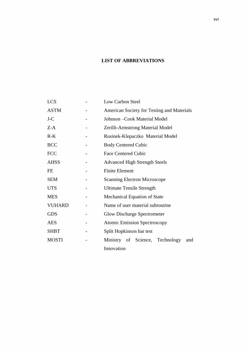
LIST OF ABBREVIATIONS
LCS
ASTM
J-C
Z-A
R-K
BCC
FCC
AHSS
FE
SEM
UTS
MES
VUHARD
GDS
AES
SHBT
MOSTI
-
-
-
-
-
-
-
-
-
-
-
-
-
-
-
-
-
Low Carbon Steel
American Society for Testing and Materials
Johnson –Cook Material Model
Zerilli-Armstrong Material Model
Rusinek-Klepaczko Material Model
Body Centered Cubic
Face Centered Cubic
Advanced High Strength Steels
Finite Element
Scanning Electron Microscope
Ultimate Tensile Strength
Mechanical Equation of State
Name of user material subroutine
Glow Discharge Spectrometer
Atomic Emission Spectroscopy
Split Hopkinson bar test
Ministry of Science, Technology and
Innovation
xvii
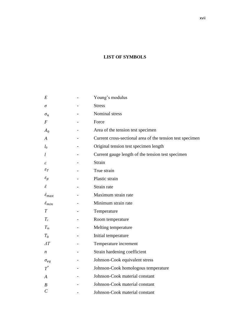
LIST OF SYMBOLS
E
σ
F
A
l0
l
ε
T
Tr
Tm
ΔT
n
T*
A
B
C
-
-
-
-
-
-
-
-
-
-
-
-
-
-
-
-
-
-
-
-
-
-
-
-
-
Young’s modulus
Stress
Nominal stress
Force
Area of the tension test specimen
Current cross-sectional area of the tension test specimen
Original tension test specimen length
Current gauge length of the tension test specimen
Strain
True strain
Plastic strain
Strain rate
Maximum strain rate
Minimum strain rate
Temperature
Room temperature
Melting temperature
Initial temperature
Temperature increment
Strain hardening coefficient
Johnson-Cook equivalent stress
Johnson-Cook homologous temperature
Johnson-Cook material constant
Johnson-Cook material constant
Johnson-Cook material constant
xviii
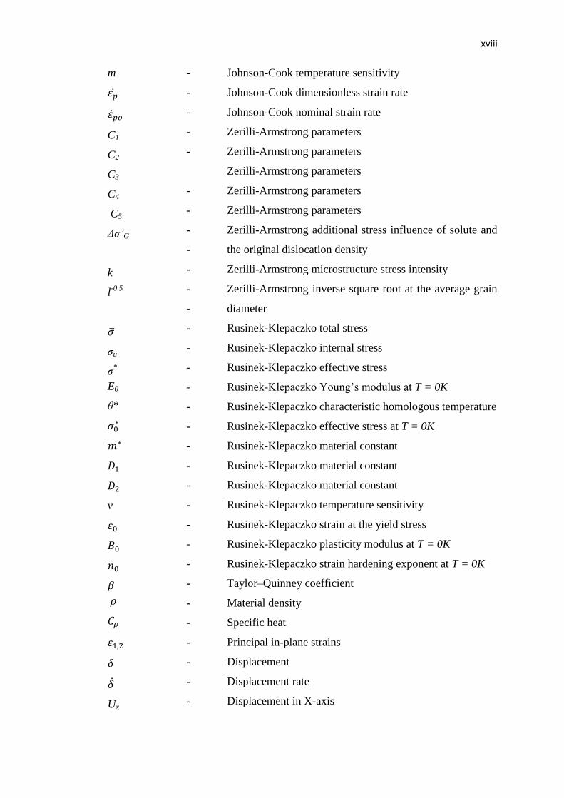
m
C1
C2
C3
C4
C5
Δσ’G
k
l-0.5
σu
σ*
E0
θ*
v
Ux
-
-
-
-
-
-
-
-
-
-
-
-
-
-
-
-
-
-
-
-
-
-
-
-
-
-
-
-
-
-
-
-
Johnson-Cook temperature sensitivity
Johnson-Cook dimensionless strain rate
Johnson-Cook nominal strain rate
Zerilli-Armstrong parameters
Zerilli-Armstrong parameters
Zerilli-Armstrong parameters
Zerilli-Armstrong parameters
Zerilli-Armstrong parameters
Zerilli-Armstrong additional stress influence of solute and
the original dislocation density
Zerilli-Armstrong microstructure stress intensity
Zerilli-Armstrong inverse square root at the average grain
diameter
Rusinek-Klepaczko total stress
Rusinek-Klepaczko internal stress
Rusinek-Klepaczko effective stress
Rusinek-Klepaczko Young’s modulus at T = 0K
Rusinek-Klepaczko characteristic homologous temperature
Rusinek-Klepaczko effective stress at T = 0K
Rusinek-Klepaczko material constant
Rusinek-Klepaczko material constant
Rusinek-Klepaczko material constant
Rusinek-Klepaczko temperature sensitivity
Rusinek-Klepaczko strain at the yield stress
Rusinek-Klepaczko plasticity modulus at T = 0K
Rusinek-Klepaczko strain hardening exponent at T = 0K
Taylor–Quinney coefficient
Material density
Specific heat
Principal in-plane strains
Displacement
Displacement rate
Displacement in X-axis
xix
Uy
URz
URx
URy
URz
σvm
Ø
-
-
-
-
-
-
-
Displacement in Y-axis
Displacement in Z-axis
Rotation about X-axis
Rotation about Y-axis
Rotation about Z-axis
von Mises stress
Diameter
xx
LIST OF APPENDICES
APPENDIX
TITLE PAGE
A
B
Derivation of Rusinek-Klapaczko Constitutive Model
Rusinek-Klapaczko Constitutive Model with Abaqus
VUHARD Subroutine
103
104
CHAPTER 1
INTRODUCTION
1.1 Background of Study
Many advanced processes in engineering such as high-speed metal forming
and cutting, metallic structures under crash and high speed impact, involve complex
thermo mechanical and multi axial loading conditions which include large strain,
high strain rates, temperature softening and adiabatic processes. Over the last few
decades, deformation of metals has been subjected to intensive study since it is of
fundamental interest in analysing failure processes. The mechanical behaviour of
sheet metals under dynamic loading such as sheet metal forming is different from
that under static or quasi-static loading. When a structure deforms in a dynamic state,
the material properties such as strength, stiffness and yield stress are affected by
strain rate [1]. As strain rate is increased from quasi-static to dynamic, conditions
change from isothermal to fully adiabatic, resulting in a gradual decrease in strength
with increasing strain rates [2]. However, the flow stress also highly depends on
many other factors such as strain path, strain rate and temperature history. This
stress-strain response can be represented using a constitutive model with temperature
and strain rate dependent variables. Only a model that includes all of these pertinent
factors is capable of predicting the complex stress state in material deformation [3].
2
Thus, the main task of constitutive model is to predict precisely the response of
engineering structures under large deformation such as impact loading [4].
In this research sheet metal behaviour under high strain rate loading which is
commonly found in the automotive industry is studied. The material properties and
behaviour are obtained from tensile testing for quasi-static state and from published
data, especially for the high strain rate state. After that, it continued with
determination of parameter extraction from experimental data for material model.
Rusinek-Klepaczko model is employed to describe the rate-dependent plastic
behaviour of sheet metal at various strain rates. Their properties include yield stress,
plastic modulus and fracture strain. Then the mechanic behaviour of sheet metal is
demonstrated using finite element method with implemented of material model. Then
all of these features are applied into thin walled tube flexural deformation test.
1.2 Overview
Sheet metals are commonly used in industrial application such as automotive
body such as low carbon sheet metal and high strength steel [5]. Most of the auto-
body metal parts are produced from sheet metal forming such as stamping process.
Moreover, in automotive industries light-weight and safe design of auto-body
structures are the main objectives and challenging to achieve in order to increase fuel
efficiency, satisfying emission-gas vehicle regulations vehicles and to ensure the
safety of passengers in the event of an accident. To achieve these objectives, crash
analyses either from experiment or numerical modelling of the high speed material
deformation have to be accurately carried out with accurate stress-strain curves at the
high strain rate. The dynamic tensile properties of auto-body steel sheets are
important since the range of the strain rate is 500 s-1
in a real auto-body crash [6] and
from 10 s-1
to 100 s-1
in sheet metal forming [3] at which the dynamic response of
steel sheets is different from quasi-static.
3
The flow stress of a material generally increases as the strain rate increases.
It is well known that the behaviour of sheet metals is strongly dependent on the strain
rate and temperature. Worked materials in these large deformation processes such as
stamping and crashworthiness experience a broad range of strain, strain rate,
temperature, and complex loading histories. To describe precisely the behaviour of
materials at high strain rates and temperatures, constitutive model which is widely
applicable and capable of accounting complex stress state in material deformation
was used [3]. The constitutive model will implement into finite element to develop
models which are widely applicable and capable of accounting for complex paths of
deformation, temperature and strain rate which represents the main requirements of
large deformation problems.
There is always a balance between testing and numerical modelling. If one
does no testing, which may be a very expensive task then the production becomes a
very high-risk effort. If one does no numerical modelling, then all design decisions
are based on experience or an expensive testing [7]. Finite element (FE) analysis is
an alternative method for investigating the sheet metal behaviour under various
loading rate issues. By using FE analysis, the mechanics behaviour of sheet metal
such as distributions and evolution of stress and strain can be predicted. Generally,
the purpose of using FE analysis is to grow the design space and shrink the test
space. For example, one of the goals of the automotive industry is to reduce the cost
associated with the safety evaluation of structures. Thus, the industry has
increasingly moved towards finite element simulation of crash tests with fewer
numbers of actual experiments. Good constitutive model is needed for the accuracy
of FE simulation results is highly dependent on material constitutive model, accurate
geometry, loading conditions and boundary conditions employed in the FE model
[7].
To develop FE model the thermo-visco-plastic behaviour of sheet metal
under higher strain rates, several constitutive relations can be found in the literature
such as Johnson-Cook (J-C) [8] model and Zerilli-Armstrong (Z-A) [9] model.
However, J-C [8] models and Z-A [9] models for work hardening of metals are not
physically based, their usage is limited only to the range of deformation conditions at
which they were curve fitted, and the accuracy is often not satisfactory. What is
4
missing in these models is the ability to capture history effects of temperature, strain
rate, and load path in manufacturing processes [3]. Temperature history effects are
magnitude in lower hardening behaviour and properties as the material. Prolonged
exponent to temperature induces creep of the material. Thus, the more sophisticated
material model which is a function of strain hardening, strain rate and temperature
sensitivities of flow stress have been proposed by Rusinek and Klepaczko (R-K) [6]
model. The R-K constitutive relation is used because the precise constitutive
modelling can predict the loading rate effects in terms of strain rate and temperature
sensitivity [6].
1.3 Problem Statement
Sheet metals such as low carbon steel and high strength steel are commonly
used to fabricate the auto-body structures. Under large deformation such as stamping
and crashworthiness, structural materials are subject to very high rates of strain and
complex loading histories. Many material properties, including those of the sheet
metal are strain rate sensitive. Consequently, quasi-static stress-strain data may not
produce accurate predictions of behaviour at high strain rates, and the use of such
data in the analysis and design of dynamically loaded structures can lead to cautious
overweight designs or premature structural failure. Because of its high flow stress,
the thermal coupling in the form of adiabatic heating leading the thermal softening
and material instabilities cannot be neglected, especially at high strain rates and large
deformation. In order to examine deformation fields under different conditions of
loadings, expensive process and testing were involved. Thus, finite element (FE)
analysis is an alternative method for investigating the sheet metal behaviour under
various loading rate issues by implementing the sophisticated constitutive model.
Therefore, to establish the model parameters and to validate the constitutive model,
experimental and FE simulation techniques are presented. The FE results then will
validate with experiments to demonstrate prediction capability of FE and constitutive
model. The R-K model is chosen in this study to accumulate predict material
5
response at varying strain rates because the model incorporates hardening, strain
rates and temperature evaluation terms.
1.4 Objectives
The objectives of this research project are:
1. To determine the properties and quantify behaviour for automotive sheet
metals of low carbon and high strength steels.
2. To validate true stress-plastic strain behaviour of sheet metal at strain
rates in the range of up to 200s-1
for low carbon sheet metal and 500s-1
for high strength steel.
3. To establish a predictive capability of Rusinek-Klepaczko (R-K)
constitutive model through FE simulation of a thin-walled tube under
flexural loading.
4. To develop FORTRAN coding of the R-K model for use in FE
simulation software
1.5 Scope of Study
The present study focuses on sheet metal behaviour and is limited to the
following scope of work:
1. The nominal sheet thicknesses for low carbon steel and DP600 are
0.7mm and 1.2mm, respectively while for thin-wall tube the thickness of
the sheet is 1mm.
2. Mechanical properties and behaviour of sheet metal will be established
in accordance to ASTM E8/E8M standards or equivalent. These tests
6
will be conducted at room temperature and at straining rates ranging
from 0.001667s-1
to 0.1667s-1
.
3. Rusinek-Klepaczko (R-K) constitutive model parameters will be
extracted from three experimental tension test data at 0.001667s-1
,
0.1667s-1
and 200s-1
for low carbon steel while three tension test data at
0.0001s-1
, 0.001667s-1
and 500s-1
for DP600.
4. A subroutine of the R-K constitutive model will be constructed writing
and implement in Abaqus software for general loading FE.
5. Finite element model on flexural test of a thin - walled tube made of low
carbon steel is simulated for prediction capability of the R-K constitutive
model.
REFERENCES
1. Kim, S. and Huh, H. Evaluation of the Failure Elongation of Steel Sheets for
an Auto-body at the Intermediate Strain Rate. Key Engineering Materials.
2008. Volumes (385-387): 749-752
2. Lee, W. S., Shyu, J.C. and Chiou, S.T. Effect of Strain Rate on Impact
Response and Dislocation Substructure of 6061-T6 Aluminum Alloy. Acta
Metallurgica. 2000. (42): 51-56
3. Guo, Y.B., Wen, Q. and Horstemeyer, M.F. An Internal State Variable
Plasticity-Based Approach to Determine Dynamic Loading History Effects on
Material Property in Manufacturing Processes. International Journal of
Mechanical Sciences. 2005. (47): 1423-1441
4. Zaera, R. and Ferna´ndez-Sa´ez, J. An Implicit Consistent Algorithm for the
Integration of Thermoviscoplastic Constitutive Equations in Adiabatic
Conditions and Finite Deformations. International Journal of Solids and
Structures. 2006. (43): 1594–1612
5. Auto/Steel Partnership. High Strength Steel Stamping Design Manual.
Southfield, Michigan. 2000.
6. Rusinek, A., Zaera, R. and Klepaczko, J.R. Constitutive relations in 3-D for a
wide range of strain rates and temperatures – Application to mild steels. Int. J.
Solids Struct. 2007. (44): 5611–5634.
7. Klepaczko, J.R., and Lodygowski, T. Advance in Constitutive Relations
Applied in Computer Codes. Italy: SpringerWienNewYork. 2009
8. Johnson, G.R. and Cook, W.H. A Constitutive Model and Data for Metals
Subjected to Large Strains, High Strain Rates and High Temperatures. In:
Proceedings of 7th International Symposium on Ballistics. 1983. 541–547.
100
9. Zerilli F.J. and Armstrong R.W. Dislocation-Mechanics-Based Constitutive
Relations for Material Dynamics Calculation. Journal of Applied Physics.
1987. (5): 1816-1825.
10. Callister, W.D. and Rethwisch, D.G. Materials Science and Engineering.
(Eight edition). Hoboken, NJ: Wiley. 2011
11. Huh, H., Lim, J. H., Kim, S. B., Han, S. S. and Park, S. H. Formability of the
Steel Sheet at the Intermediate Strain Rate. Key Engineering Materials. 2004
Vols. (274-276): 403-408
12. Yu, H., Guo, Y. and Lai, X. Constitutive Model on the Description of Plastic
Behavior of DP600 Steel at Strain Rate from 10-4
s-1
to 103 s
-1. Computational
Materials Science. 2009. (46): 36-41.
13. Klepaczko, J.R., Rusinek, A., Rodríguez-Martínez, J.A., Pe˛cherski, R.B. and
Arias, A. Modelling of Thermo-Viscoplastic Behaviour of DH-36 and
Weldox 460-E Structural Steels at Wide Ranges of Strain Rates and
Temperatures, Comparison of Constitutive Relations for Impact Problems.
Mechanic of Materials. 2009 (41):599–621
14. Gorham, D.A. The Effect of Specimen Dimensions on High Strain Rate
Compression Measurements of Copper. J. Phys. D: Appl. Phys. 1991. (24):
1489-1492.
15. Gorham, D.A.; Pope, P.H. and Field, J.E. (1992). An Improved Method for
Compressive Stress Strain Measurements at Very High Strain Rates. Proc. R.
Soc. Lond. 1992. ( A 438):153-170.
16. Manna, I., Majumdar, J. D., Chandra, B. R., Nayak, S. And Dahotre, N. B.
Laser surface cladding of Fe–B–C, Fe–B–Si and Fe–BC–Si–Al–C on plain