Section 4 - Using the Transmitter in pH Mode 12LCD Menu 13 - 28
Section 5 - Using the Transmitter in ORP Mode 29LCD Menu 30 - 44
Section 6 - Using the Transmitter in Conductivity Mode 45LCD Menu 46 - 62
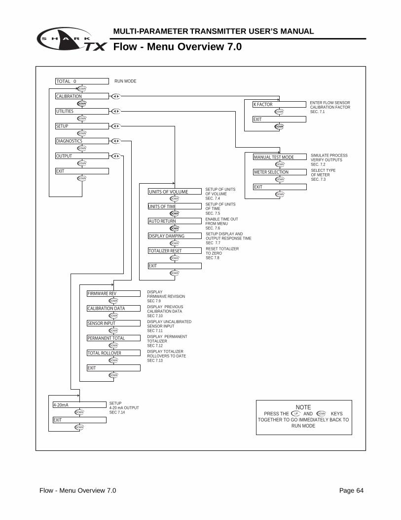
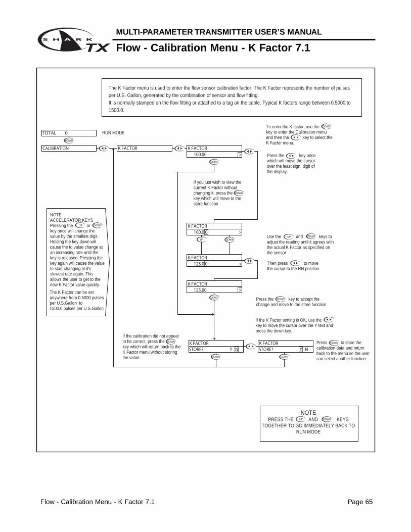
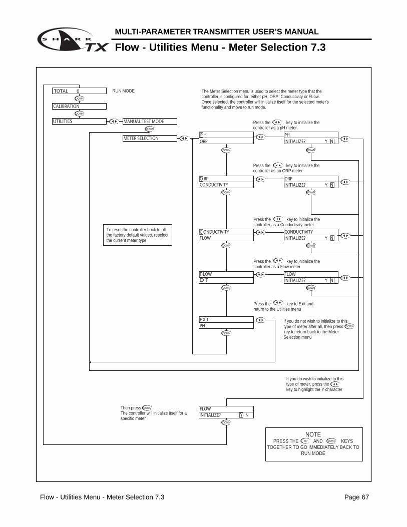
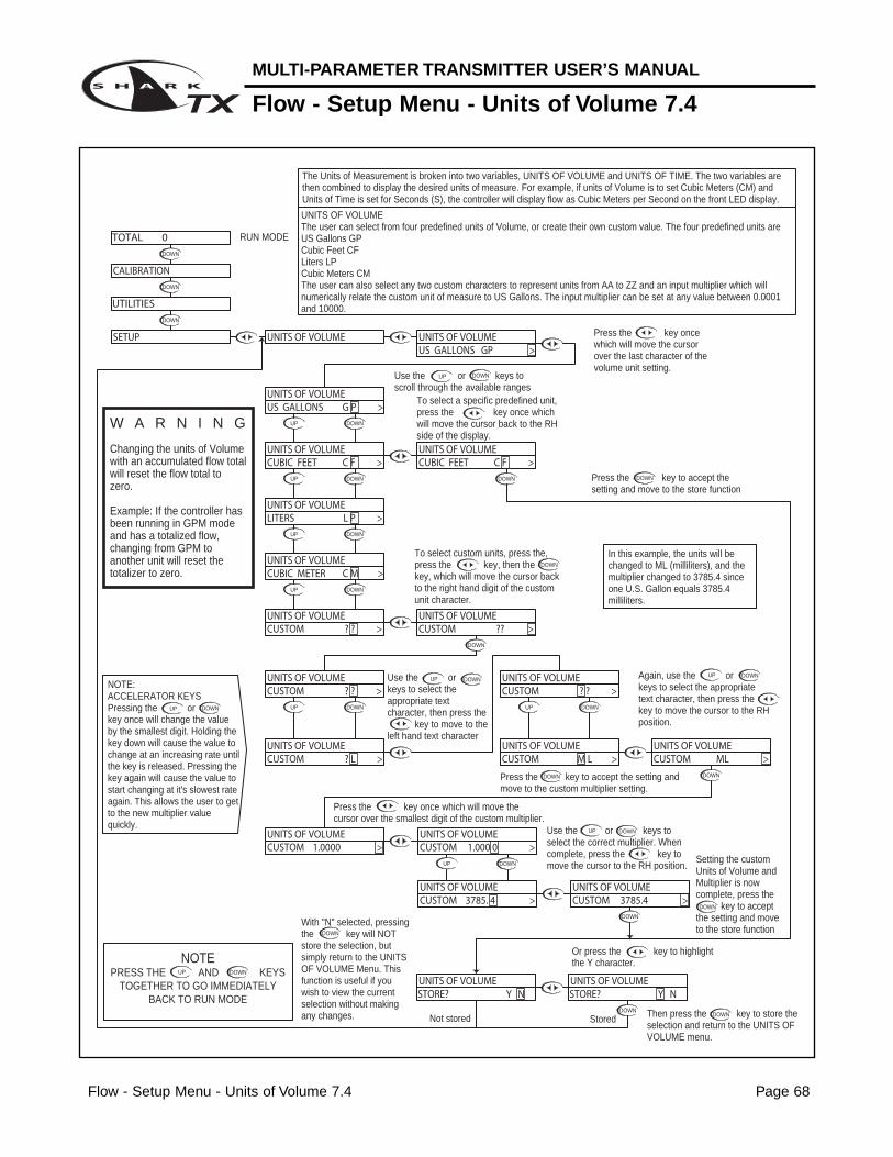
Section 7 - Using the Transmitter in Flow Mode 63LCD Menu 64 - 78
Appendix A - Probe Configuration Table 79
Return Policy & Warranty Plan 80
MULTI-PARAMETER TRANSMITTER USER’S MANUAL
Table of Contents
MULTI-PARAMETER TRANSMITTER USER’S MANUAL
Introduction
Introduction Page 1
The SHARKTX & SHARKTXP multi-parameter transmitter is a microprocessor basedtransmitter capable of measuring one of the following parameters, pH, ORP, conductivi-ty or flow.
When shipped from the factory, the Shark is not set to measure any one parameter.When the Shark is powered up for the first time, it will display the meter selectionscreen where the meter type must be selected. (refer to section 4.5 Meter Selection)
This meter selection screen will only be displayed when the Shark is powered up for thefirst time.
After the user selects a meter type the Shark will remain set to that meter type until it ischanged with the meter selection menu function in the Utilities menu.
To return the Shark to its factory settings, the user must re-select the current meter typefrom the meter selection menu function. This will override all set-points and return allsettings back to the factory settings.
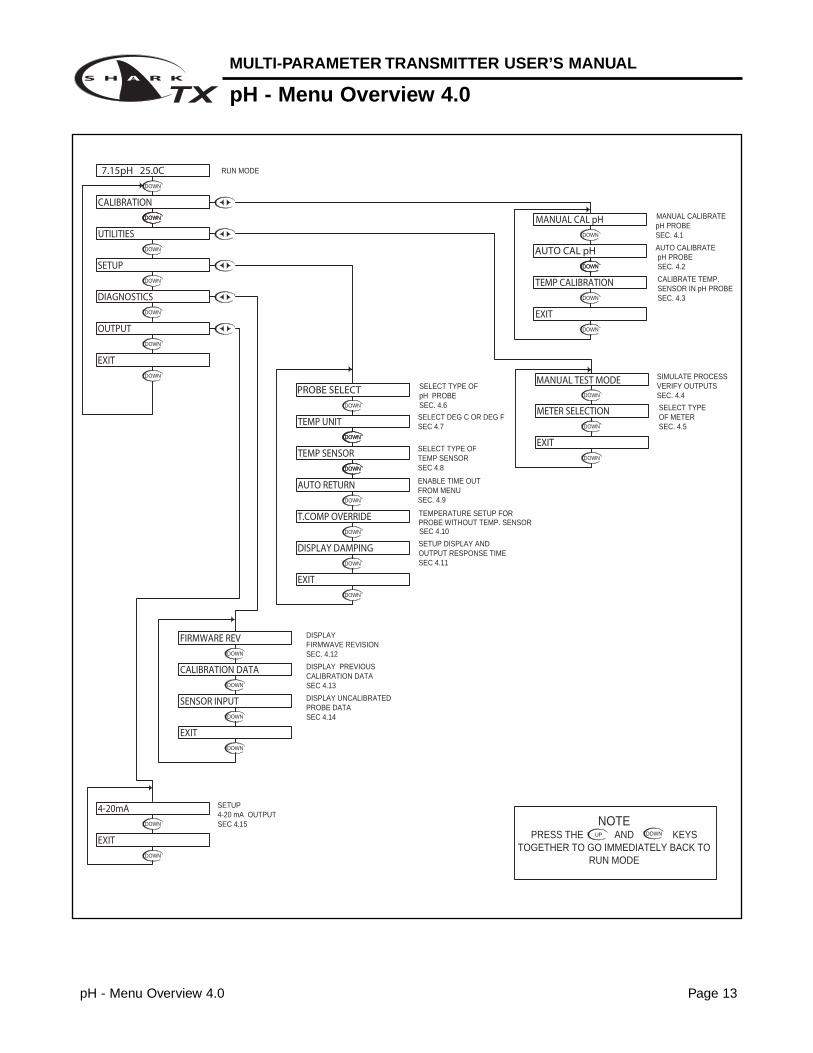
The Shark Users menu has been divided into five main categories
- Calibration, used to calibrate the Shark with the selected sensor- Utilities, used to manually control or override the outputs.- Setup, used to configure the Sharks many options- Diagnostics, used to troubleshoot problems with the Shark or sensor- Outputs, used to configure the Shark’s 4 to 20mA output.
SHARKTX is packaged in a rugged NEMA 4X polycarbonate enclosure with a universalmounting kit for surface, panel and pipe-mount applications. This enclosure is perfect forstand-alone or panel-mount operation.
SHARKTXP enclosure is also polycarbonate with a NEMA 4X front panel. Panel mount,and DIN rail mounting hardware are supplied.
MΩ/cm3 0 to 19.99 0.01
uS/cm3
0 to 2.000 0.01
0 to 20.00 0.1
0 to 200.0 0.1
0 to 5000 1.0
mS/cm30 to 20.00 10
0 to 200.0 50
Section I - Specifications Page 2
MULTI-PARAMETER TRANSMITTER USER’S MANUAL
Section I - Specifications
pH ORP Conductivity FlowDisplay 2 x 16 alpha-numeric LCD display
Power Requir ements 4 to 20mA, Loop Powered, 16 to 32 VDC
Flow: 0 to 9999 with selectable
flow rate units
pH: 0.01 to 14.00 ORP: -1999 to +1999mV Volume: 0 - 999 with Auto Range
Measuring Range (Dependent on sensor) Flow rate units: Gallons (GP), Cubic
Temp: 0 to 100°C or Temp: 0 to 100°C or Feet (CF), Liters (LP), Cubic Meters
32° to +212°F 32° to +212°F (CM), custom by entering factor
related to Gallons
Time units: Seconds (S), Minutes (M)
Temp: 0 to 100°C or 32° to +212°F Hours (H)
Automatic or Manual
Temperatur e Automatic or Manual Not required
User selectable temperature Not required
Compensation 0 - 100°C (32° to +212°F) compensation slope 0.0 to 10.0%/°C.
0 to 100°C (32° to +212°F)
Temperatur e Unit °C or °F Not required
Temperatur e Sensor User selectable: 300Ω NTC Thermistor, 3000Ω NTC Thermistor or Pt. 1000 RTD Not required
Auto-Calibration Manual Calibration
Dry Calibration
Calibration Modes Manual Calibration Temperature Calibration
Sample Calibration K factor Input
Temperature Calibration Temperature Calibration
Ambient Conditions Temperature: -20°C to +60°C or -4°F to +140°F Humidity: 0 to 90% RH (non-condensing)
Sensor to Transmitter Differential Sensor: 3000 ft 300 ft 2000 ft
Distance Combination Sensor: 10 ft
Analog Output 4 to 20mA
Isolated Output, Range expand 0 to 100% of full scale (min segment 10% of full scale), max. load 800ΩMemory Back-up All user settings are retained indefinitely in memory (EEPROM)
SHARKTX Enclosure: NEMA 4X, 1/4 DIN, polycarbonate enclosure with two 1/2” conduit holes
Mechanical SHARKTXP Enclosure: NEMA 4X front panel, 1/4 DIN, polycarbonate
SHARKTX Mounting: Universal Mounting kit for surface, pipe and panel mount included
SHARKTXP Mounting: Panel and DIN rail mount included
Sensor Input Probe: -600 to +600mV Probe: -1999 to +1999mV Cell: 0 to 9999ΩPaddle: 0 to 2000Hz
Temp. Sensor: 0 to 9999Ω Temp. Sensor: 0 to 9999Ω Temp. Sensor: 0 to 9999ΩInvalid Entries Invalid entries cannot be stored
Manual Test Mode Process value can be simulated with arrow keys to verify correct setup of output
Output Hold 4 to 20mA output is placed on hold when the transmitter is in Menu mode
Recall data from lastRecall data from last calibration, calibration mode, calibration, calibration buffer
Calibration Data 1st & 2nd accepted buffer value and probe mV output, accepted value, and cell Recall store K factor.calibration temperature, calibration slope, and probe resistance, calibrationefficiency temperature
Auto Retur n User selectable auto return if the transmitter is left in menu mode for more than 10 min.
Display Damping User can select rate at which the transmitter updates display. Enables display damping of unstable process
Net Weight SHARKTX: 0.71 lbs (0.32 kg)
SHARKTXP: 0.25 lbs (0.12 kg)
Appr ovals ULC (pending)
MULTI-PARAMETER TRANSMITTER USER’S MANUAL
Section 2 - Installation
Section 2 - Installation Page 3
2.1 Unpacking
Save the shipping carton and packing material in case the instrument needs to be stored orreturned. Inspect the instrument and packing material for shipping damage and report anyproblems immediately.
2.2 Location
Locate the transmitter close to the sensor. The list below gives typical maximum distances forvarious sensors. Refer to the sensor specifications for exact information.
• Aquametrix Differential PH Probe 3000 ft (914 meters)• Aquametrix Combination PH Probe 10 ft (3 meters)• Aquametrix Conductivity Probe 300 ft (91 meters)• Aquametrix Flow sensor 2000 ft (610 meters)
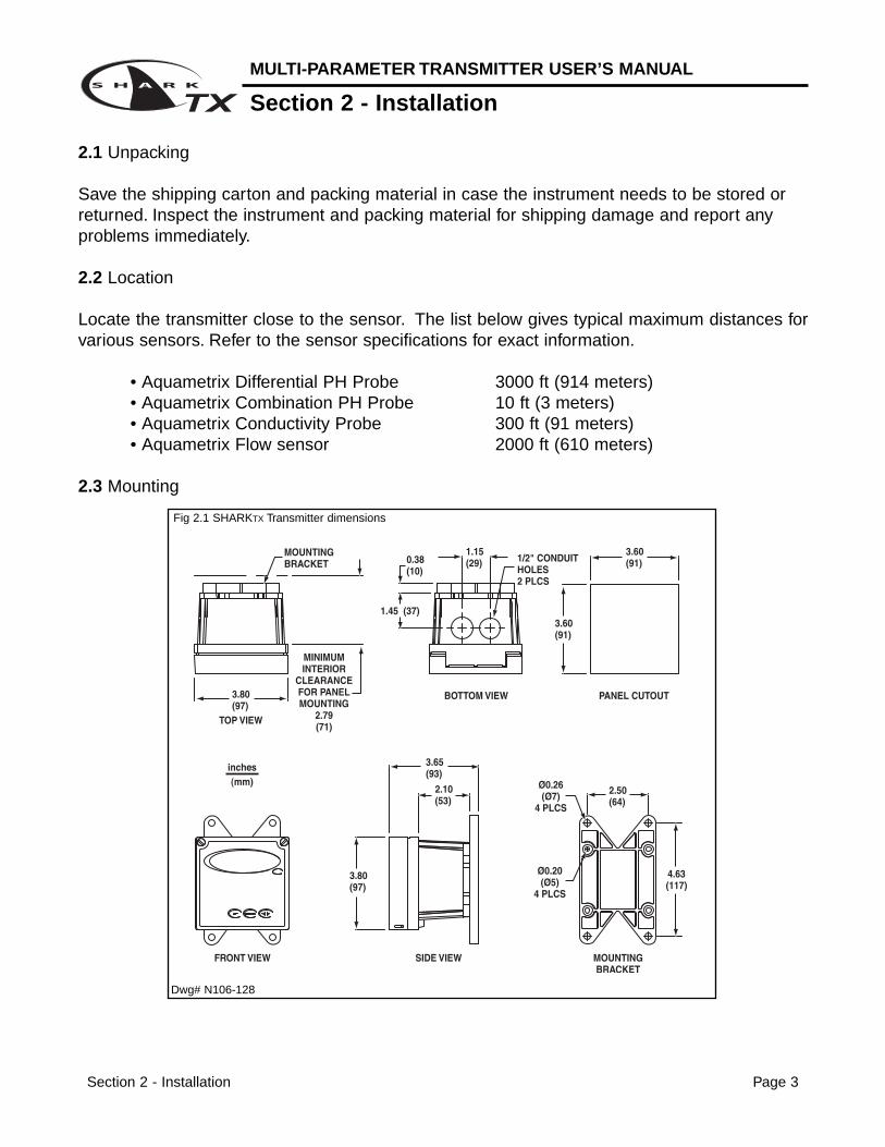
2.3 Mounting
Fig 2.1 SHARKTX Transmitter dimensions
Dwg# N106-128
Section 2 - Installation Page 4
MULTI-PARAMETER TRANSMITTER USER’S MANUAL
Section 2 - Installation
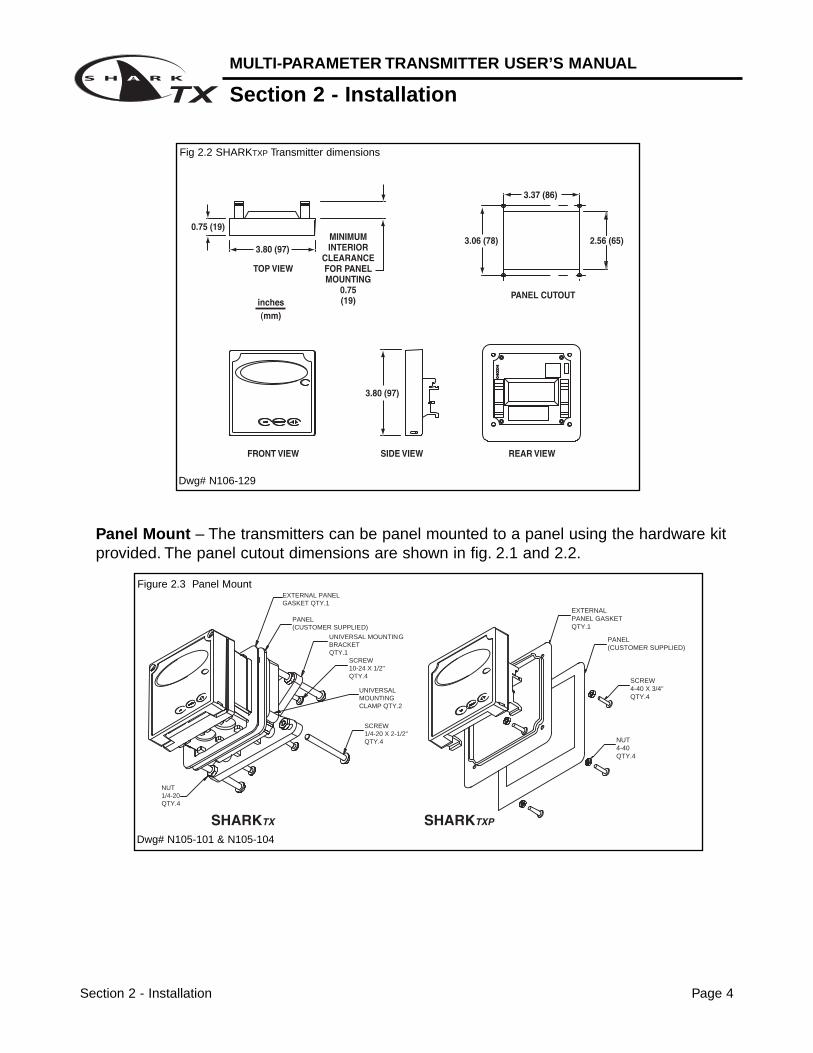
Panel Mount – The transmitters can be panel mounted to a panel using the hardware kitprovided. The panel cutout dimensions are shown in fig. 2.1 and 2.2.
EXTERNAL PANEL GASKETQTY.1
SCREW4-40 X 3/4"QTY.4
NUT4-40QTY.4
PANEL (CUSTOMER SUPPLIED)
PANEL(CUSTOMER SUPPLIED)
EXTERNAL PANEL GASKET QTY.1
SCREW 1/4-20 X 2-1/2"QTY.4
NUT1/4-20 QTY.4
UNIVERSAL MOUNTINGCLAMP QTY.2
SCREW10-24 X 1/2"QTY.4
UNIVERSAL MOUNTING BRACKETQTY.1
Figure 2.3 Panel Mount
Fig 2.2 SHARKTXP Transmitter dimensions
Dwg# N106-129
Dwg# N105-101 & N105-104
MULTI-PARAMETER TRANSMITTER USER’S MANUAL
Section 2 - Installation
Section 2 - Installation Page 5
MIN. PIPE DIA.1" PIPE (NOMINAL)
MAX. PIPE DIA.2" PIPE (NOMINAL)
NUT10-24QTY.4
SCREW 10-24 X 3-1/2"QTY.4
UNIVERSAL MOUNTING BRACKETQTY.1
Figure 2.6 Horizontal Pipe Mount
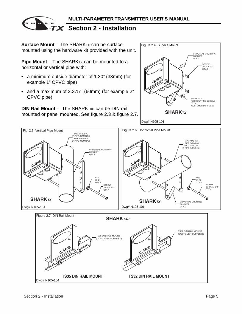
Surface Mount – The SHARKTX can be surfacemounted using the hardware kit provided with the unit.
Pipe Mount – The SHARKTX can be mounted to ahorizontal or vertical pipe with:
• a minimum outside diameter of 1.30” (33mm) (forexample 1” CPVC pipe)
• and a maximum of 2.375” (60mm) (for example 2”CPVC pipe)
DIN Rail Mount – The SHARKTXP can be DIN railmounted or panel mounted. See figure 2.3 & figure 2.7.
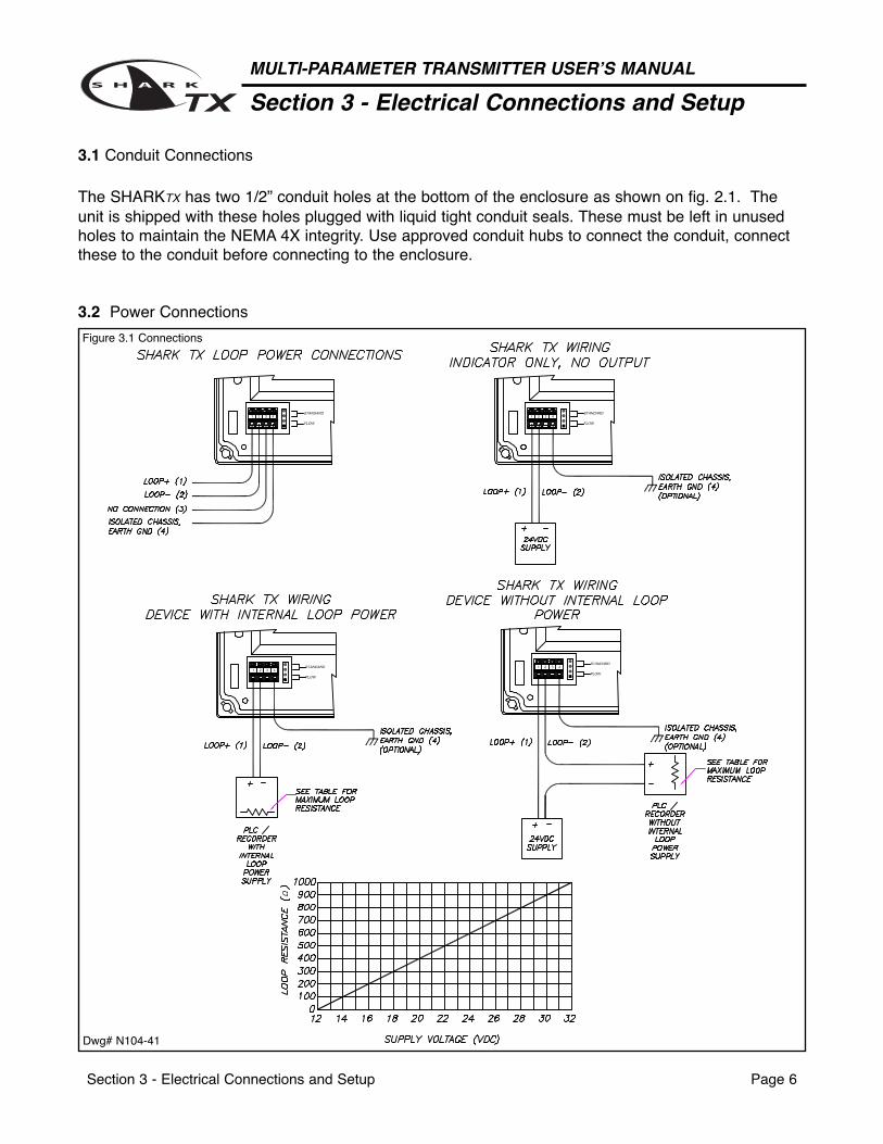
The SHARKTX has two 1/2” conduit holes at the bottom of the enclosure as shown on fig. 2.1. Theunit is shipped with these holes plugged with liquid tight conduit seals. These must be left in unusedholes to maintain the NEMA 4X integrity. Use approved conduit hubs to connect the conduit, connectthese to the conduit before connecting to the enclosure.
3.2 Power Connections
Section 3 - Electrical Connections and Setup Page 6
MULTI-PARAMETER TRANSMITTER USER’S MANUAL
Section 3 - Electrical Connections and Setup
Figure 3.1 Connections
Dwg# N104-41
MULTI-PARAMETER TRANSMITTER USER’S MANUAL
Section 3 - Electrical Connections and Setup
Section 3 - Electrical Connections and Setup Page 7
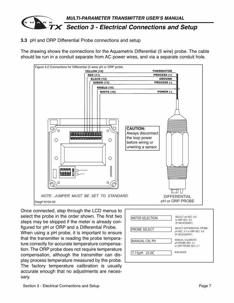
3.3 pH and ORP Differential Probe connections and setup
The drawing shows the connections for the Aquametrix Differential (5 wire) probe. The cableshould be run in a conduit separate from AC power wires, and via a separate conduit hole.
Figure 3.2 Connections for Differential (5 wire) pH or ORP probe
Once connected, step through the LCD menus toselect the probe in the order shown. The first twosteps may be skipped if the meter is already con-figured for pH or ORP and a Differential Probe.When using a pH probe, it is important to ensurethat the transmitter is reading the probe tempera-ture correctly for accurate temperature compensa-tion. The ORP probe does not require temperaturecompensation, although the transmitter can dis-play process temperature measured by the probe.The factory temperature calibration is usuallyaccurate enough that no adjustments are neces-sary.
Dwg# N104-42
CAUTION:Always disconnectthe loop powerbefore wiring orunwiring a sensor
Section 3 - Electrical Connections and Setup Page 8
MULTI-PARAMETER TRANSMITTER USER’S MANUAL
Section 3 - Electrical Connections and Setup
3.4 pH or ORP Combination Probe connections and setup
The drawing shows the connections for the Aquametrix Combination probe. The cable should be runin a conduit separate from AC power wires, and via a separate conduit hole. The cable length shouldnot exceed 10 feet (3 meters).
Fig. 3.3 Connections for the 2 and 4 wire Combination Probe
Once connected, step through the LCD menus to select the probe in the order shown. The first two stepsmay be skipped if the meter is already configured for a Combination Probe. If a two wire pH probe isused, which has no temperature sensor, ensure that the Temp. Comp. Override is set to same temper-ature as the buffer before calibrating. If a two wire ORP probe is used, you can blank the Temp displaywith the T DISP OVERRIDE menu.
The 2 wire version hasno temperature sensorand is connected via acoaxial wire.In a pH meter, the usershould set the T COMPOVERRIDE menu to ON(Section 4.10) and adjustthe temperature setting tothe actual probe temper-ature.In an ORP meter, theuser should set theT.DISP OVERRIDE toON (Section 5.9) to blankthe temperature readingon the display.
The 4 wire version hastwo additional wires forthe probe internal tem-perature sensor. Ensurethat the T COMP OVER-RIDE or T.DISP OVER-RIDE is OFF.
Dwg# N104-43
CAUTION:Always disconnectthe loop powerbefore wiring orunwiring a sensor
MULTI-PARAMETER TRANSMITTER USER’S MANUAL
Section 3 - Electrical Connections and Setup
Section 3 - Electrical Connections and Setup Page 9
3.5 Conductivity Cell (Contacting style) connections and setup
Figure 3.4 Connections for Conductivity Cells
Once connnected, stepthrough the LCD menus toselect the cell in the ordershown. The TEMP COMPCURVE setup default is1.8%/deg C. This is accept-able for most process appli-cations. If your process issignificantly different fromthis, change the setting inthe TEMP COMP CURVEmenu.
The drawing shows the connections for the Aquametrix Conductivity Cells (Contacting style). The cableshould be run in a conduit seperate from the AC power wires, and via a seperate conduit hole. The cellcable length should not exceed 300ft. (91 meters).
Dwg# N104-44
CAUTION:Always disconnectthe loop powerbefore wiring orunwiring a sensor
Section 3 - Electrical Connections and Setup Page 10
MULTI-PARAMETER TRANSMITTER USER’S MANUAL
Section 3 - Electrical Connections and Setup
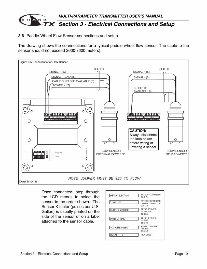
3.6 Paddle Wheel Flow Sensor connections and setup
Figure 3.5 Connections for Flow Sensor
Once connected, step throughthe LCD menus to select thesensor in the order shown. TheSensor K factor (pulses per U.S.Gallon) is usually printed on theside of the sensor or on a labelattached to the sensor cable.
The drawing shows the connnections for a typical paddle wheel flow sensor. The cable to thesensor should not exceed 2000’ (600 meters).
Dwg# N104-45
CAUTION:Always disconnectthe loop powerbefore wiring orunwiring a sensor
Section 3 - Electrical Connections and Setup Page 11
MULTI-PARAMETER TRANSMITTER USER’S MANUAL
Section 3 - Electrical Connections and Setup
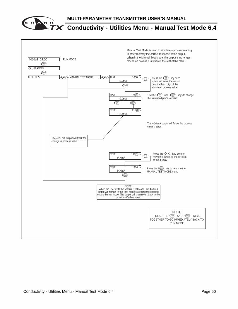
3.10 MANUAL TEST MODE(LCD MENU SECTIONS - pH: 4.4, ORP: 5.3, Conductivity: 6.4, Flow: 7.2)
The setup can be tested using Manual Test Mode to simulate process changes.
MANUAL TEST MODE is used to simulate a process reading in order to verify the correctresponse of the output.
3.11 4-20 mA Isolated Output (LCD MENU SECTIONS - pH: 4.15, ORP: 5.14, Conductivity: 6.16, Flow: 7.14)
The Transmitter has a single 4 to 20mA output, electrically isolated from the ground. The outputcan source current into a resistive load. Maximum resistance depends on supply voltage.Drawing on page 6 (Fig. 3.1)
The output is dedicated to track the process and has fully independent and fully adjustable 4 &20 mA output setpoints. This will enable the operator to span the output over the desired range.
The output can be precisely trimmed through the LCD menu for precision applications.
The drawing on page 6 (Fig. 3.1) shows the connections for the output.
Section 4 - Using the Transmitter in pH Mode Page 12
SIMPLE THREE-BUTTON INTERFACEFOR FAST & EASY SETUP(REFER TO SECTIONS 4.0 TO 4.15)
2 LINE, 16 CHARACTER LCD DISPLAY
MAIN MENU INTERFACE SCREEN
1/4" TURN SCREWS(FOR SHARKTX ONLY)
UNIT LABELLABEL TO INDICATE UNIT OF MEASURE SHARK IS CONFIGURED FOR.
MULTI-PARAMETER TRANSMITTER USER’S MANUAL
pH - Menu Overview 4.0
pH - Menu Overview 4.0 Page 13
DOWN
DOWN
DOWN
DOWN
DOWN
DOWN
DOWN
DOWN
DOWN
DOWN
DOWN
DOWNDOWN
DOWNDOWN
DOWN
DOWN
DOWNDOWN
DOWN
DOWN
DOWN
DOWN
DOWN
DOWN
DOWN
DOWNDOWN
SELECT DEG C OR DEG F
ENABLE TIME OUT
PROBE WITHOUT TEMP. SENSORTEMPERATURE SETUP FOR
SETUP DISPLAY AND OUTPUT RESPONSE TIME
SELECT TYPE OF
FROM MENU
DISPLAYFIRMWAVE REVISIONSEC. 4.12
DISPLAY PREVIOUS CALIBRATION DATASEC 4.13
DISPLAY UNCALIBRATEDPROBE DATASEC 4.14
SEC. 4.9
SEC 4.10
SEC 4.11
SEC. 4.6
SEC 4.7
SELECT TYPE OFTEMP SENSORSEC 4.8
pH PROBE
RUN MODE
SEC. 4.3
UP
NOTEPRESS THE AND KEYS
TOGETHER TO GO IMMEDIATELY BACK TO RUN MODE
DOWN
SELECT TYPEOF METERSEC. 4.5
VERIFY OUTPUTSSIMULATE PROCESS
SEC. 4.4
AUTO CALIBRATE
MANUAL CALIBRATE
SENSOR IN pH PROBECALIBRATE TEMP.
pH PROBESEC. 4.1
pH PROBESEC. 4.2
DIAGNOSTICS
EXIT
SENSOR INPUT
CALIBRATION DATA
FIRMWARE REV
EXIT
DISPLAY DAMPING
T.COMP OVERRIDE
EXIT
AUTO RETURN
TEMP UNIT
TEMP SENSOR
PROBE SELECT
7.15pH 25.0C
UTILITIES
SETUP
CALIBRATION
MANUAL TEST MODE
METER SELECTION
EXIT
EXIT
TEMP CALIBRATION
MANUAL CAL pH
AUTO CAL pH
DOWN
DOWN
DOWN
4-20 mA OUTPUTSETUP
SEC 4.15
EXIT
4-20mA
OUTPUT
pH - Calibration Menu - Manual Calibrate 4.1 Page 14
MULTI-PARAMETER TRANSMITTER USER’S MANUAL
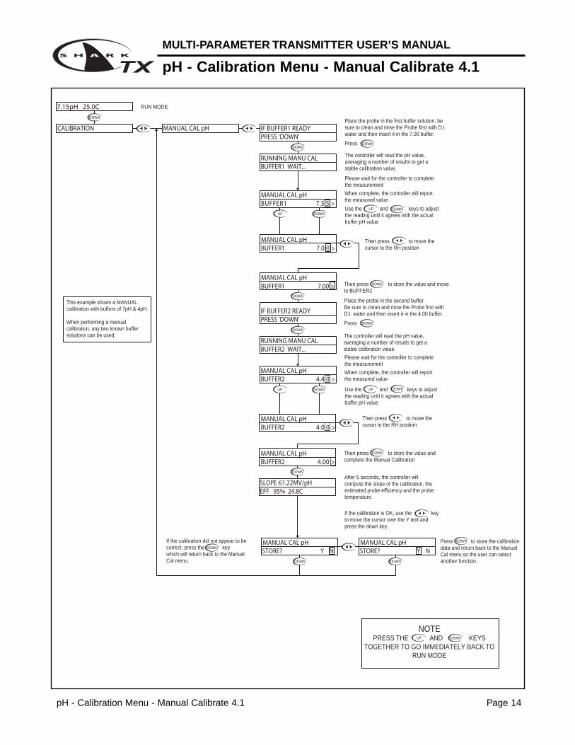
pH - Calibration Menu - Manual Calibrate 4.1
DOWN
DOWN
DOWN
UP DOWN
DOWN
DOWN
UP DOWN
DOWN
DOWN
DOWN
DOWN
DOWN
DOWN
UP DOWN
DOWN
UP DOWN
DOWN
Please wait for the controller to complete the measurement
After 5 seconds, the controller willcompute the slope of the calibration, the estimated probe efficiency and the probe temperature.
Then press to store the value and complete the Manual Calibration
Then press to store the value and move to BUFFER2
Use the and keys to adjust the reading until it agrees with the actual buffer pH value
When complete, the controller will report the measured value
The controller will read the pH value, averaging a number of results to get a stable calibration value.
Place the probe in the second buffer.Be sure to clean and rinse the Probe first with D.I. water and then insert it in the 4.00 buffer.
Press
Use the and keys to adjust the reading until it agrees with the actual buffer pH value
When complete, the controller will report the measured value
Please wait for the controller to complete the measurement
The controller will read the pH value, averaging a number of results to get a stable calibration value.
Place the probe in the first buffer solution, be sure to clean and rinse the Probe first with D.I. water and then insert it in the 7.00 buffer.
Press
If the calibration is OK, use the key to move the cursor over the Y text and press the down key.
If the calibration did not appear to be correct, press the key which will return back to the Manual Cal menu.
RUN MODE
UP
NOTEPRESS THE AND KEYS
TOGETHER TO GO IMMEDIATELY BACK TO RUN MODE
DOWN
Press to store the calibration data and return back to the Manual Cal menu so the user can select another function.
Then press to move the cursor to the RH position
Then press to move the cursor to the RH position
STORE? Y N STORE? Y N
IF BUFFER1 READYCALIBRATION MANUAL CAL pH
MANUAL CAL pH
MANUAL CAL pHBUFFER2 4.00 >
SLOPE 61.22MV/pHEFF 95% 24.8C
BUFFER1 7.00 >
MANUAL CAL pHBUFFER2 4.4 0 >
MANUAL CAL pHBUFFER2 4.0 0 >
BUFFER2 WAIT...RUNNING MANU CAL
IF BUFFER2 READYPRESS 'DOWN'
MANUAL CAL pH
MANUAL CAL pHBUFFER1 7.0 0 >
RUNNING MANU CALBUFFER1 WAIT...
PRESS 'DOWN'
BUFFER1 7.3 5 >MANUAL CAL pH
7.15pH 25.0C
MANUAL CAL pH
This example shows a MANUAL calibration with buffers of 7pH & 4pH.
When performing a manual calibration, any two known buffer solutions can be used.
MULTI-PARAMETER TRANSMITTER USER’S MANUAL
pH - Calibration Menu - Auto Calibrate 4.2
pH - Calibration Menu - Auto Calibrate 4.2 Page 15
DOWN
DOWN DOWN
DOWN
DOWN
DOWN
DOWN
DOWN
DOWNDOWN
DOWN
DOWN
If an erros occurs, the controller will indicate a "BUFFER ERROR" alarm. This could be caused by- using a defective buffer- incorrect probe wiring- defective probe
Press to return to the Auto cal menu, try to correct the problem and calibrate again, or go to the diagnotics menus to test the probesee Section 4.16
If an erros occurs, the controller will indicate a "BUFFER ERROR" alarm. This could be caused by- using the same buffer twice- using a defective buffer- incorrect probe wiring- defective probe
Press to return to the Auto cal menu, try to correct the problem and calibrate again, or go to the diagnotics menus to test the probe
If the calibration did not appear to be correct, press the key which will return back to the Auto cal menu.
UP
NOTEPRESS THE AND KEYS
TOGETHER TO GO IMMEDIATELY BACK TO RUN MODE
DOWN
This will store the calibration data and return back to the Auto cal setup so the user can select another function.
If the calibration is OK, use the key to move the cursor over the Y text and press the down key.
After 5 seconds, the controller willcompute the slope of the calibration, the estimated probe efficiency and the probe temperature.
When complete, the controller will report the measured value
When complete, the controller will report the measured value
Press the key to move to Buffer 2
Please wait for the controller to complete the measurement
The controller will read the pH value, averaging a number of results to get a stable calibration value.
Place the probe in the second buffer solution.Be sure to clean and rinse the Probe first with D.I. water and then insert it in the 4.00 buffer.
Press the key
Please wait for the controller to complete the measurement
The controller will read the pH value, averaging a number of results to get a stable calibration value.
Place the probe in the first buffer solution, be sure to clean and rinse the Probe first with D.I. water and then insert it in the 7.00 buffer.
Press
RUN MODE
AUTO CAL pH
STORE? Y N STORE? Y N AUTO CAL pH
AUTO CAL pH
EFF 95% 24.8CSLOPE 61.22MV/pH
BUFFER2 4.00 >
AUTO CAL pH
AUTO CAL pH
BUFFER ERRORCONTINUE >
RUNNING AUTO CALBUFFER2 WAIT...
BUFFER1 7.00 >
PRESS 'DOWN'IF BUFFER2 READY
BUFFER ERRORCONTINUE >
PRESS 'DOWN'IF BUFFER1 READY
RUNNING AUTO CALBUFFER1 WAIT...
CALIBRATION
7.15pH 25.0C
MANUAL CAL pH
This example shows an AUTO calibration with buffers of 7pH & 4pH.
When performing an auto calibration, any two standard buffers of 4.00, 7.00 or 10.00 pH can be used. The buffers will be automatically recognized if the probe measures them within +/- 1 pH of their nominal value.
pH - Calibration Menu - Temperature Calibration 4.3 Page 16
MULTI-PARAMETER TRANSMITTER USER’S MANUAL
pH - Calibration Menu - Temperature Calibration 4.3
DOWN
DOWN DOWN
DOWNUP
DOWN
DOWN
DOWNUP
DOWN
DOWN
DOWN
DOWN
DOWN
If the Temperature Compensation Override is set to ON (see section 4.11), the Shark cannot calibrate the temperature sensor. This display will appear to alert the user to the condition.
If the calibration does not appear to be correct, press the key which will return back to the Temp Calibration menu.
UP
NOTEPRESS THE AND KEYS
TOGETHER TO GO IMMEDIATELY BACK TO RUN MODE
DOWN
This will store the calibration data and return back to the Temp Calibration setup so the user can select another function.
Use the and to adjust the reading until it agrees with the known temperature of the probe
Press the key to accept the reading and move to the store function
"T FACTOR SHIFTED" will be displayed for 5 seconds to indicate that the temperature sensor has been calibrated. The Shark will then move to the store function.
The controller displays the current probe temperature.If this incorrect, the controller can be adjusted to compensate.
Press the key once which will move the cursor back to the RH side of temperature display.
Press the key once which will move the cursor over the least sign. digit of the temperature display.
RUN MODE
AUTO CAL pH
STORE? Y NTEMP CALIBRATION
STORE? Y N TEMP CALIBRATION
TEMP CALIBRATION 25.0C >
T FACTOR SHIFTED
25. 0 C >TEMP CALIBRATION
TEMP CALIBRATION
TEMP CALIBRATION
TEMP CALIBRATION 22. 4 C >
22.4C >
TEMP CALIBRATIONTEMP O/R ON >
7.15pH 25.0C
CALIBRATION MANUAL CAL pH
MULTI-PARAMETER TRANSMITTER USER’S MANUAL
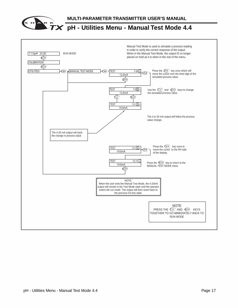
pH - Utilities Menu - Manual Test Mode 4.4
pH - Utilities Menu - Manual Test Mode 4.4 Page 17
DOWN
DOWN
DOWN
UP DOWN
DOWN
UP DOWN
Manual Test Mode is used to simulate a process reading in order to verify the correct response of the output. When in the Manual Test Mode, the output IS no longer placed on hold as it is when in the rest of the menu.
NOTE:When the user exits the Manual Test Mode, the 4-20mA
output will remain in the Test Mode state until the operator enters the run mode. The output will then revert back to
the previous On-line state.
The 4-20 mA output will track the change in process value
RUN MODE
UP
NOTEPRESS THE AND KEYS
TOGETHER TO GO IMMEDIATELY BACK TO RUN MODE
DOWN
Press the key once to move the cursor to the RH side of the display
The 4 to 20 mA output will follow the process value change.
Press the key to return to the MANUAL TEST MODE menu
Use the and keys to change the simulated process value.
Press the key once which will move the cursor over the least digit of the simulated process value.
TEST 7.0 0 >
TEST 7.00 >
7.15pH 25.0C
CALIBRATION
UTILITIES
19.0mA
19.0mA
TEST 13.1 5 >
TEST 13.15 >
MANUAL TEST MODE 12.0mA
12.0mA
19.0mATEST 13.1 5 >
DOWN
pH - Utilities Menu - Meter Selection 4.5 Page 18
MULTI-PARAMETER TRANSMITTER USER’S MANUAL
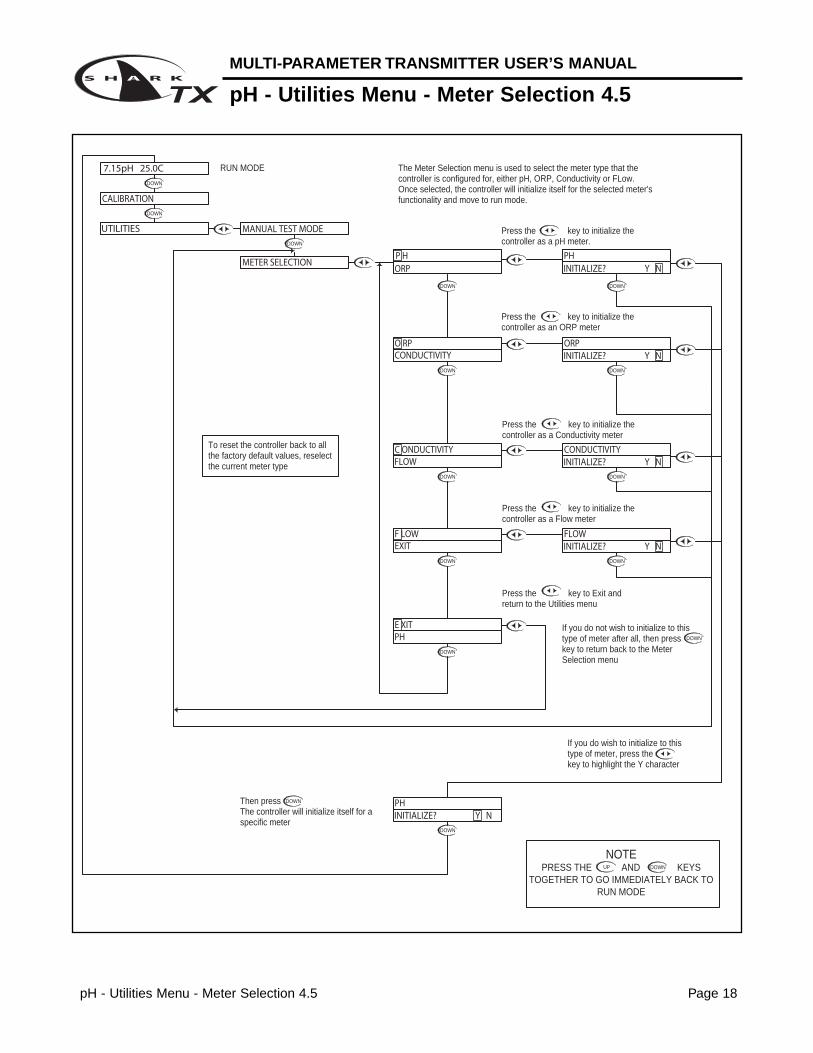
pH - Utilities Menu - Meter Selection 4.5
DOWNDOWN
DOWN
DOWN
DOWN
DOWN
DOWN
DOWN
DOWN
DOWN
DOWN
DOWN
DOWN DOWN
DOWN
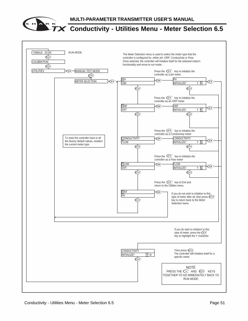
If you do not wish to initialize to this type of meter after all, then press key to return back to the Meter Selection menu
Then press The controller will initialize itself for a specific meter
If you do wish to initialize to this type of meter, press the key to highlight the Y character
UP
NOTEPRESS THE AND KEYS
TOGETHER TO GO IMMEDIATELY BACK TO RUN MODE
DOWN
Press the key to Exit and return to the Utilities menu
RUN MODE
Press the key to initialize the controller as a Flow meter
Press the key to initialize the controller as a Conductivity meter
The Meter Selection menu is used to select the meter type that the controller is configured for, either pH, ORP, Conductivity or FLow. Once selected, the controller will initialize itself for the selected meter's functionality and move to run mode.
Press the key to initialize the controller as an ORP meter
Press the key to initialize the controller as a pH meter.
INITIALIZE? Y N
INITIALIZE? Y N
INITIALIZE? Y N
INITIALIZE? Y N
INITIALIZE? Y NPH
PHE XIT
MANUAL TEST MODE
7.15pH 25.0C
UTILITIES
CALIBRATION
METER SELECTION
C ONDUCTIVITYFLOW
EXITF LOW
CONDUCTIVITYO RP
CONDUCTIVITY
FLOW
ORP
P HORP
PH
To reset the controller back to all the factory default values, reselect the current meter type
MULTI-PARAMETER TRANSMITTER USER’S MANUAL
pH - Setup Menu - Probe Select 4.6
pH - Setup Menu - Probe Select 4.6 Page 19
DOWN
DOWN
DOWN
DOWN
DOWN
DOWN
UP DOWN
DOWN
DOWN
DOWN
UP DOWN
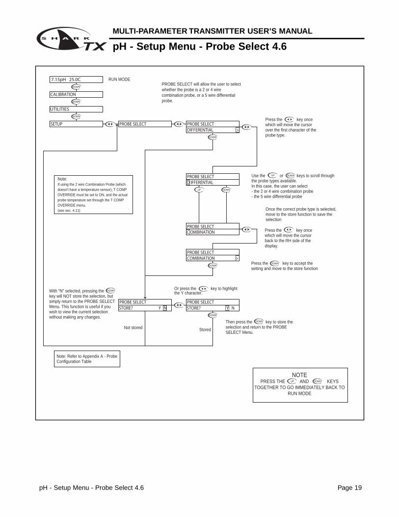
Then press the key to store the selection and return to the PROBE SELECT Menu.
With "N" selected, pressing the key will NOT store the selection, but simply return to the PROBE SELECT Menu. This function is useful if you wish to view the current selection without making any changes.
Not stored Stored
Or press the key to highlightthe Y character.
Note:If using the 2 wire Combination Probe (which doesn't have a temperature sensor), T COMP OVERRIDE must be set to ON, and the actual probe temperature set through the T COMP OVERRIDE menu.(see sec. 4.11)
PROBE SELECT will allow the user to select whether the probe is a 2 or 4 wire combination probe, or a 5 wire differential probe.
RUN MODE
UP
NOTEPRESS THE AND KEYS
TOGETHER TO GO IMMEDIATELY BACK TO RUN MODE
DOWN
Use the or keys to scroll through the probe types available. In this case, the user can select - the 2 or 4 wire combination probe- the 5 wire differential probe
Press the key to accept the setting and move to the store function
Press the key once which will move the cursor back to the RH side of the display.
Once the correct probe type is selected, move to the store function to save the selection
Press the key once which will move the cursor over the first character of the probe type.
STORE? Y N STORE? Y N PROBE SELECT PROBE SELECT
7.15pH 25.0C
UTILITIES
SETUP
CALIBRATION
PROBE SELECTCOMBINATION >
C OMBINATIONPROBE SELECT
D IFFERENTIALPROBE SELECT
PROBE SELECT PROBE SELECTDIFFERENTIAL >
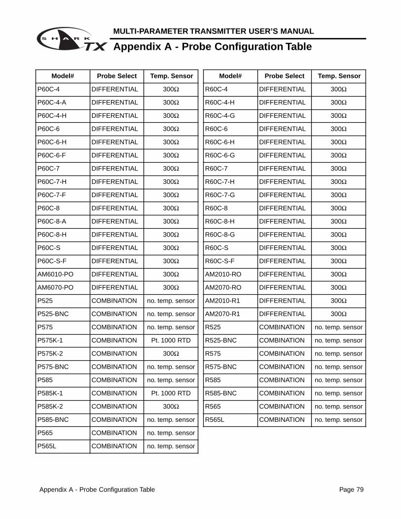
Note: Refer to Appendix A - Probe Configuration Table
pH - Setup Menu - Temp Unit 4.7 Page 20
MULTI-PARAMETER TRANSMITTER USER’S MANUAL
pH - Setup Menu -Temp Unit 4.7
DOWN
DOWN
DOWN
DOWN
DOWN
DOWN DOWN
DOWN
DOWN
UP DOWN
DOWN
UP DOWN
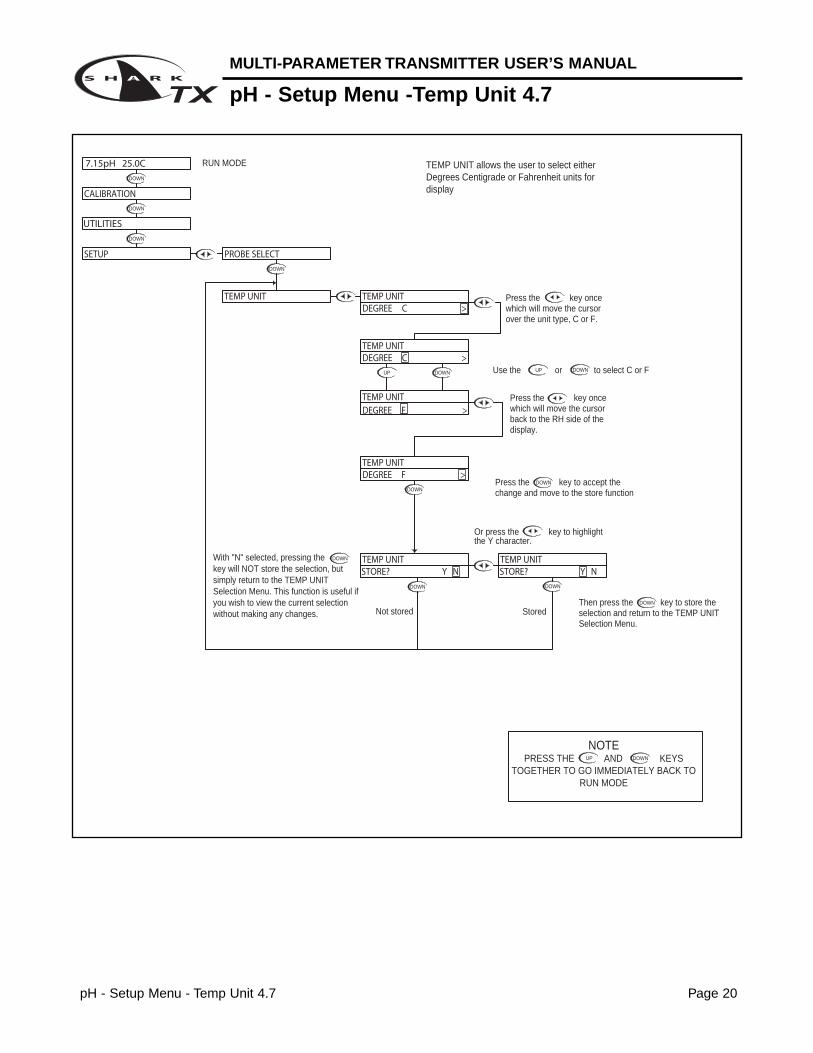
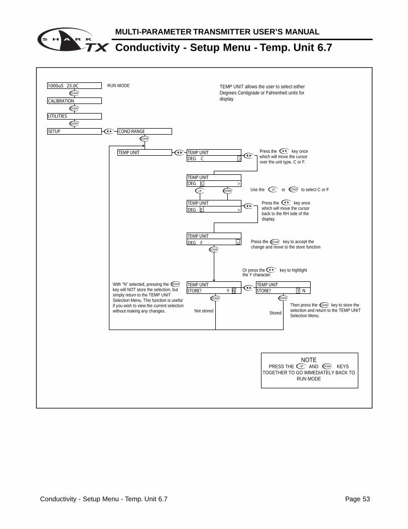
With "N" selected, pressing the key will NOT store the selection, but simply return to the TEMP UNIT Selection Menu. This function is useful if you wish to view the current selection without making any changes.
RUN MODE
Or press the key to highlight
UP
NOTEPRESS THE AND KEYS
TOGETHER TO GO IMMEDIATELY BACK TO RUN MODE
DOWN
Then press the key to store the selection and return to the TEMP UNIT Selection Menu.
Not stored Stored
the Y character.
Use the or to select C or F
Press the key to accept the change and move to the store function
Press the key once which will move the cursor over the unit type, C or F.
Press the key once which will move the cursor back to the RH side of the display.
TEMP UNIT allows the user to select either Degrees Centigrade or Fahrenheit units for display
7.15pH 25.0C
CALIBRATION
UTILITIES
SETUP
TEMP UNIT
PROBE SELECT
STORE? Y N STORE? Y N TEMP UNIT TEMP UNIT
DEGREE C >
DEGREE F >TEMP UNIT
DEGREE F >
DEGREE C >
TEMP UNIT
TEMP UNIT
TEMP UNIT
MULTI-PARAMETER TRANSMITTER USER’S MANUAL
pH - Setup Menu - Temp. Sensor 4.8
pH - Setup Menu - Temp. Sensor 4.8 Page 21
DOWN
DOWN
DOWN
DOWN
DOWN
DOWN
DOWN
DOWN
DOWN
UP
UP
DOWN
DOWN
DOWN
UP DOWN
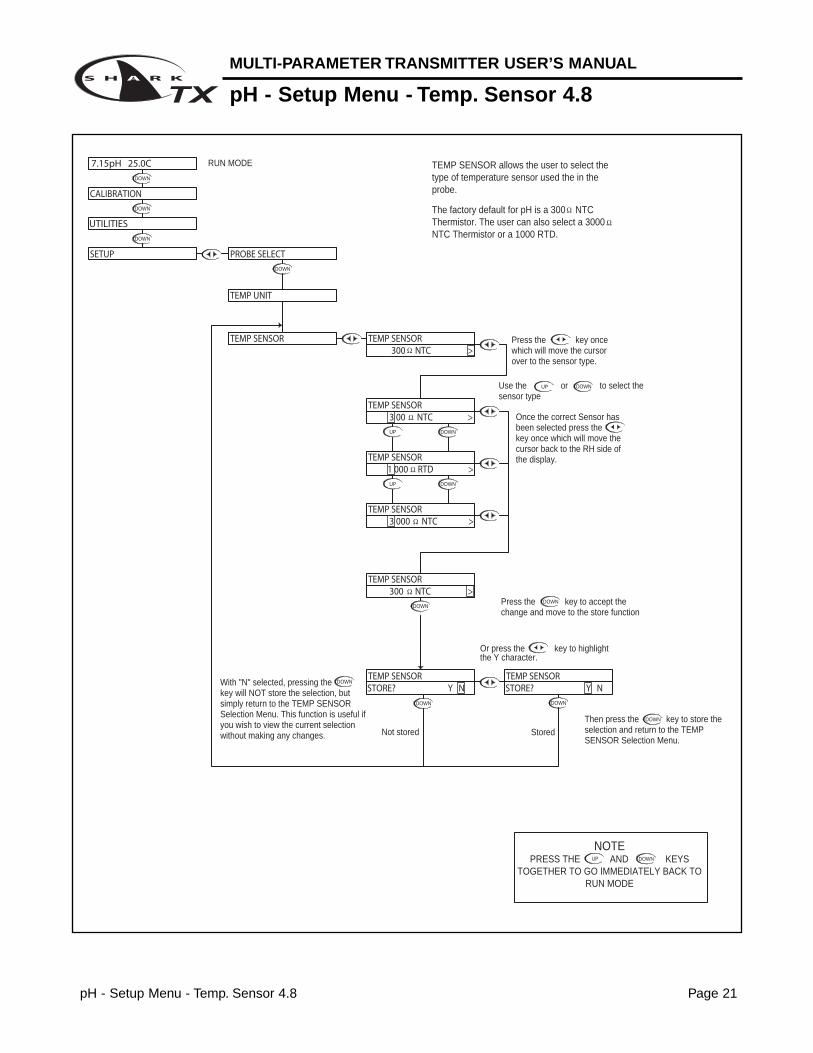
the Y character.Or press the key to highlight
With "N" selected, pressing the key will NOT store the selection, but simply return to the TEMP SENSOR Selection Menu. This function is useful if you wish to view the current selection without making any changes. Not stored
UP
NOTEPRESS THE AND KEYS
TOGETHER TO GO IMMEDIATELY BACK TO RUN MODE
DOWN
Press the key to accept the change and move to the store function
Then press the key to store the selection and return to the TEMP SENSOR Selection Menu.
Stored
TEMP SENSOR allows the user to select the type of temperature sensor used the in the probe.
The factory default for pH is a 300 NTC Thermistor. The user can also select a 3000 NTC Thermistor or a 1000 RTD.
RUN MODE
Use the or to select the sensor type
Once the correct Sensor has been selected press the key once which will move the cursor back to the RH side of the display.
Press the key once which will move the cursor over to the sensor type.
7.15pH 25.0C
SETUP
UTILITIES
CALIBRATION
STORE? Y N STORE? Y N TEMP SENSOR
300 NTC >
3 000 NTC >
TEMP SENSOR
Ω
TEMP SENSOR
TEMP UNIT
TEMP SENSOR
1 000 RTD >
TEMP SENSOR
TEMP SENSOR
3 00 NTC >TEMP SENSOR
Ω
Ω
300 NTC >TEMP SENSOR
PROBE SELECT
Ω
Ω
Ω
Ω
pH - Setup Menu - Auto Return 4.9 Page 22
MULTI-PARAMETER TRANSMITTER USER’S MANUAL
pH - Setup Menu - Auto Return 4.9
DOWN
DOWN
DOWN
DOWN
Not stored
DOWN
Stored
DOWN DOWN
DOWN
DOWN
DOWN
DOWN
DOWN
DOWN
UP DOWN
DOWNUP
UP
NOTEPRESS THE AND KEYS
TOGETHER TO GO IMMEDIATELY BACK TO RUN MODE
DOWN
With "N" selected, pressing the key will NOT store the selection, but simply return to the AUTO RETURN Selection Menu. This function is useful if you wish to view the current selection without making any changes.
Then press the key to store the selection and return to the Auto Return Selection Menu.
Press the key to accept the change and move to the STORE function
Or press the key to highlightthe Y character.
RUN MODE
To change the MENU RETURN setting,Press the key once which will move the cursor to the ON or OFF text
Use the or keys to select either ON or OFF.
Press the key once which will move the cursor back to the RH side of the display.
MENU ON will cause the controller to exit the menu and revert back to the online run mode after 10 minutes with no buttons pressed. This feature ensures that if a user forgets to return back to run mode, the controller will not be left in an offline state. If for some reason, the user would like to remain in the menu mode for extended periods of time, the AUTO RETURN function can be set to "OFF".
AUTO RETURN is used to select what conditions will cause the controller to time-out of the operations menu
7.15pH 25.0C
SETUP
UTILITIES
CALIBRATION
STORE? Y N STORE? Y N AUTO RETURN AUTO RETURN
AUTO RETURNAUTO RETURNMENU ON >
TEMP SENSOR
TEMP UNIT
PROBE SELECTION
AUTO RETURN
MENU OFF >AUTO RETURN
AUTO RETURN
MENU O FF >
MENU O N >
MULTI-PARAMETER TRANSMITTER USER’S MANUAL
pH - Setup Menu - T.Comp Override 4.10
pH - Setup Menu - T.Comp Override 4.10 Page 23
UP
DOWN
UP
DOWN
DOWN
DOWN
DOWN DOWN
DOWN
DOWNUP
DOWN
DOWN
DOWN
DOWN
DOWN
DOWN
DOWN
DOWN
DOWN
DOWNUP
DOWN
DOWN
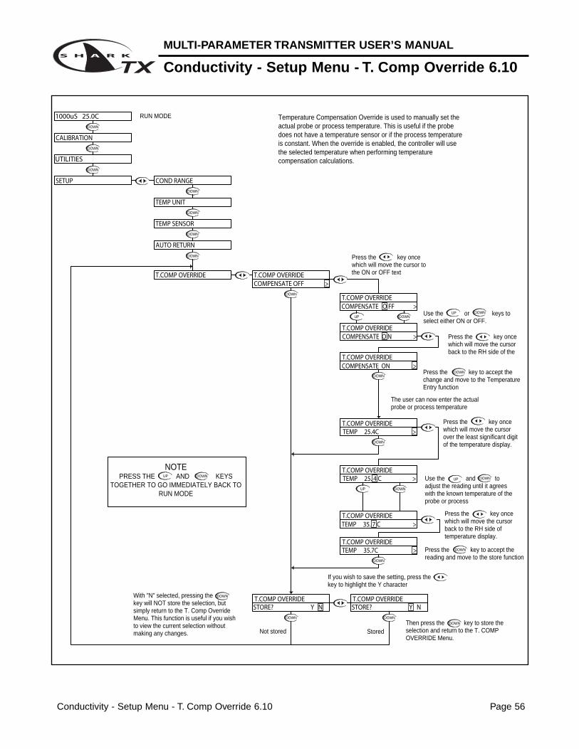
DOWNUse the or keys to select either ON or OFF.
Press the key to accept the change and move to the Temperature Entry function
Press the key once which will move the cursor back to the RH side of the display.
Press the key once which will move the cursor over the least significant digit of the temperature display.
Use the and to adjust the reading until it agrees with the known temperature of the probe or process
Press the key to accept the reading and move to the store function
Press the key once which will move the cursor back to the RH side of temperature display.
The user can now enter the actual probe or process temperature
Then press the key to store the selection and return to the T. COMP OVERRIDE Menu.
UP
NOTEPRESS THE AND KEYS
TOGETHER TO GO IMMEDIATELY BACK TO RUN MODE
DOWN
With "N" selected, pressing the key will NOT store the selection, but simply return to the T. Comp Override Menu. This function is useful if you wish to view the current selection without making any changes.
If you wish to save the setting, press the key to highlight the Y character
Not stored Stored
RUN MODE
Press the key once which will move the cursor to the ON or OFF text
Temperature Compensation Override is used to manually set the actual probe or process temperature. This is useful if the probe does not have a temperature sensor or if the process temperature is constant. When the override is enabled, the controller will use the selected temperature when performing temperature compensation calculations.
T.COMP OVERRIDE
STORE? Y N STORE? Y N
TEMP 35. 7 C >
TEMP 35.7C >T.COMP OVERRIDE
T.COMP OVERRIDE T.COMP OVERRIDE
TEMP 25. 4 C >T.COMP OVERRIDE
T.COMP OVERRIDETEMP 25.4C >
AUTO RETURN
T.COMP OVERRIDE
CALIBRATION
UTILITIES
SETUP
7.15pH 25.0C
TEMP UNIT
TEMP SENSOR
PROBE SELECTION
COMPENSATE O FF >
COMPENSATE O N >T.COMP OVERRIDE
T.COMP OVERRIDE
COMPENSATE O N >T.COMP OVERRIDE
COMPENSATE OFF >T.COMP OVERRIDE
pH - Setup Menu - Display Damping 4.11 Page 24
MULTI-PARAMETER TRANSMITTER USER’S MANUAL
pH - Setup Menu - Display Damping 4.11
DOWN
DOWN
DOWN
DOWN
DOWN
DOWN
DOWN
DOWN
DOWN
DOWN
DOWN
DOWN
DOWN
DOWN
UP
DOWNUP
DOWN
UP
NOTEPRESS THE AND KEYS
TOGETHER TO GO IMMEDIATELY BACK TO RUN MODE
DOWN
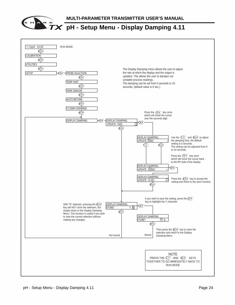
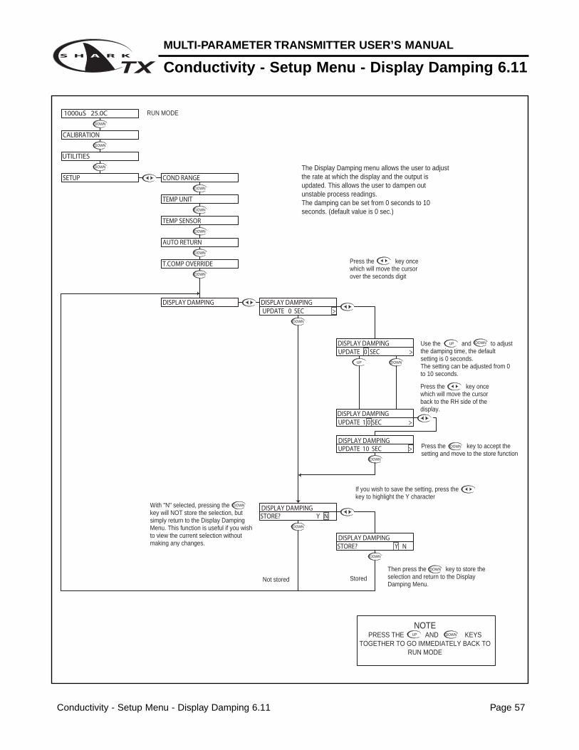
The Display Damping menu allows the user to adjust the rate at which the display and the output is updated. This allows the user to dampen out unstable process readings. The damping can be set from 0 seconds to 10 seconds. (default value is 0 sec.)
With "N" selected, pressing the key will NOT store the selection, but simply return to the Display Damping Menu. This function is useful if you wish to view the current selection without making any changes.
Not stored
RUN MODE
Use the and to adjust the damping time, the default setting is 0 seconds.The setting can be adjusted from 0 to 10 seconds.
Then press the key to store the selection and return to the Display Damping Menu.Stored
If you wish to save the setting, press the key to highlight the Y character
Press the key once which will move the cursor back to the RH side of the display.
Press the key to accept the setting and move to the store function
Press the key once which will move the cursor over the seconds digit
STORE? Y N
UPDATE 10 SEC >
UPDATE 0 SEC >
DISPLAY DAMPING
UPDATE 1 0 SEC >
DISPLAY DAMPING
DISPLAY DAMPING
DISPLAY DAMPING
STORE? Y NDISPLAY DAMPING
7.15pH 25.0C
CALIBRATION
SETUP
UTILITIES
DISPLAY DAMPING
AUTO RETURN
T.COMP OVERRIDE
DISPLAY DAMPINGUPDATE 0SEC >
TEMP UNIT
PROBE SELECTION
DOWN
TEMP SENSOR
pH - Diagnostics Menu - Firmware Rev 4.12 Page 25
MULTI-PARAMETER TRANSMITTER USER’S MANUAL
pH - Diagnostics Menu - Firmware Rev 4.12
DOWN
DOWN
DOWN
DOWN
DOWN
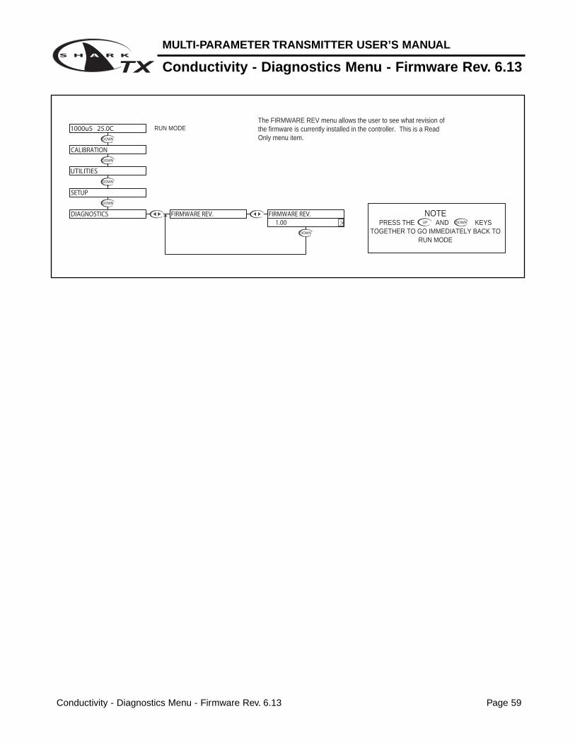
The FIRMWARE REV menu allows the user to see what revision of the firmware is currently installed in the controller. This is a Read Only menu item.
RUN MODE
UP
NOTEPRESS THE AND KEYS
TOGETHER TO GO IMMEDIATELY BACK TO RUN MODE
DOWN
7.15pH 25.0C
DIAGNOSTICS
SETUP
UTILITIES
CALIBRATION
FIRMWARE REV. FIRMWARE REV. 1.00 >
MULTI-PARAMETER TRANSMITTER USER’S MANUAL
pH - Diagnostics Menu - Calibration Data 4.13
pH - Diagnostics Menu - Calibration Data 4.13 Page 26
DOWN
DOWN
DOWN
DOWN
DOWN
DOWN
DOWN
DOWN
DOWN
DOWN
DOWN DOWN
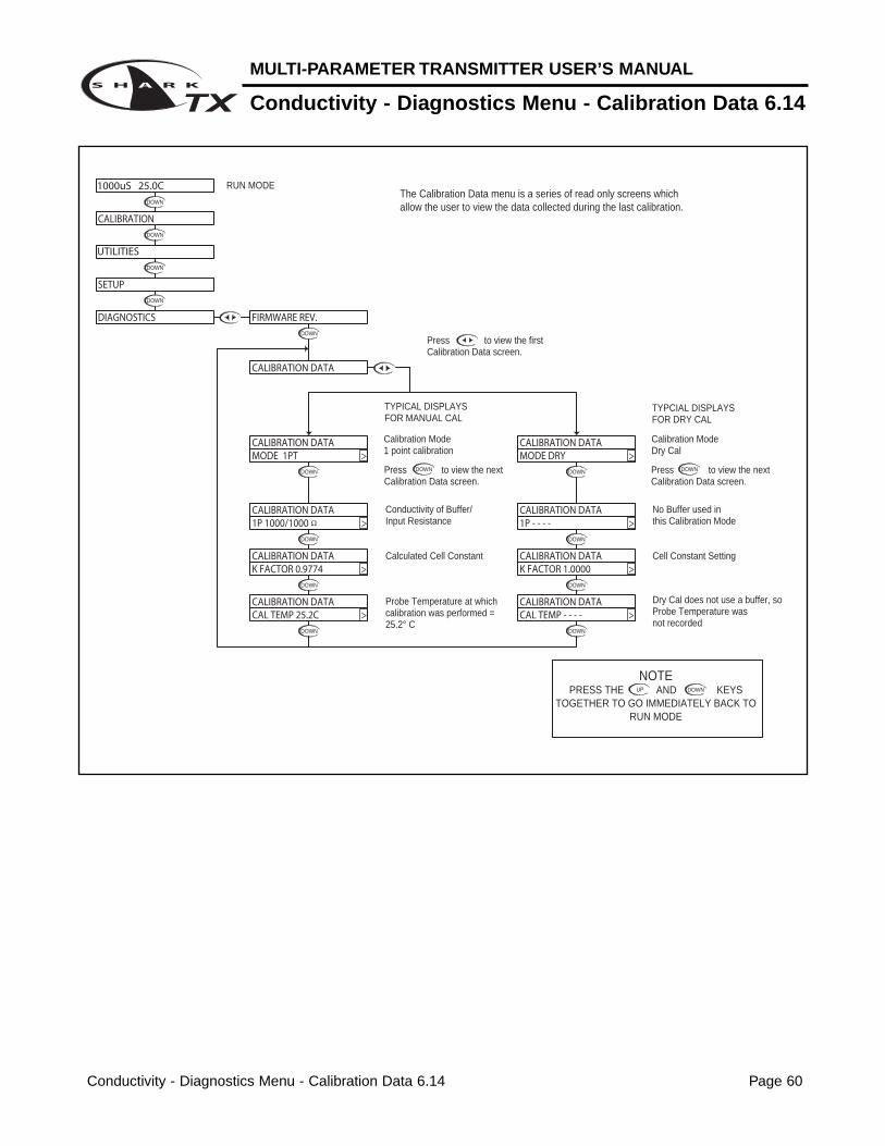
The Calibration Data menu is a series of read only screens which allow the user to view the data collected during the last calibration.
RUN MODE
Press to view the first Calibration Data screen.
UP
NOTEPRESS THE AND KEYS
TOGETHER TO GO IMMEDIATELY BACK TO RUN MODE
DOWN
1st POINT PH = 7.00INPUT FROM PROBE = - 19 mV
Calculated efficiency based on 2 point calibration = 91 %
Calculated slope based on 2 point calibration = 59.16 mV/pH
Probe Temperature at which calibration was performed = 19.4°C
2nd POINT PH = 4.00INPUT FROM PROBE = + 143 mV
Calibration Mode2 point calibration
Press to view the next Calibration Data screen.
EFF 91% >
59.16MV/PH >
CALIBRATION DATACAL TEMP 19.4C >
CALIBRATION DATA2P 4.00/ 143 >
CALIBRATION DATA1P 7.00/ -19 >
MODE 2PT >CALIBRATION DATA
7.15pH 25.0C
DIAGNOSTICS
CALIBRATION
UTILITIES
SETUP
CAL EFFICIENCY
CAL SLOPE
CALIBRATION DATA
FIRMWARE REV.
pH - Diagnostics Menu - Sensor Input 4.14 Page 27
MULTI-PARAMETER TRANSMITTER USER’S MANUAL
pH - Diagnostics Menu - Sensor Input 4.14
DOWN
DOWN
DOWN
DOWN
DOWN
DOWN
DOWN
UP
NOTEPRESS THE AND KEYS
TOGETHER TO GO IMMEDIATELY BACK TO RUN MODE
DOWN
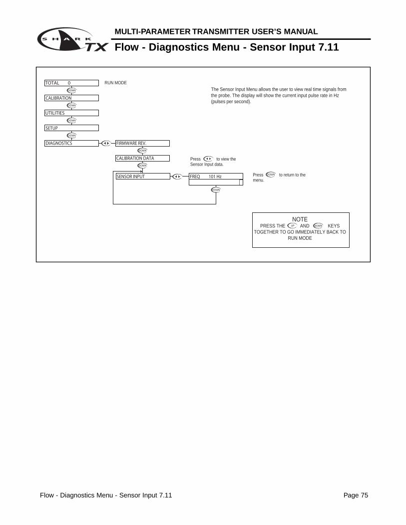
The Sensor Input Menu allows the user to view real time, uncompensated process data from the probe.This is a Read only menu item.
The top line shows the mV input from the probeThe bottom line shows the actual value of the temperature sensor in ohms.
Press to view the Sensor Input data.
CALIBRATION DATA
SETUP
DIAGNOSTICS
SENSOR INPUT
FIRMWARE REV.
7.15pH 25.0C
UTILITIES
CALIBRATION
TEMP 331Ω >PROBE -18mV
RUN MODE
Troubleshooting a pH probe using the sensor input
Sensor input displays the uncompensated sensor input data. The pH probe values are dis-played in mV (millivolts). The temperature sensor value is displayed in Ω (ohm).
Connect the pH probe as per Probe Configuration Table in Appendix A.
1. Place the probe in buffer 7pH (allow temperature to stabilize)• Probe should read 0mV [±50mV]• Temperature should read 300Ω [±50Ω] @ 25°C• Record both of these numbers.
2. Place the probe in buffer 4pH• Probe should read +160mV more than probe value at 7pH• Temperature should read the same as in 7pH
3. Place the probe in buffer 10pH• Probe should read -160mV less then probe value at 7pH• Temperature should read the same as in 7pH
MULTI-PARAMETER TRANSMITTER USER’S MANUAL
pH - Output Menu - 4-20mA Output 4.15
pH - Output Menu - 4-20mA Output 4.15 Page 28
DOWN
DOWN DOWN
DOWN DOWN
DOWN
UP
DOWN
DOWN
DOWN
DOWN
DOWN
DOWN
DOWN
DOWN
DOWN
UP DOWN
UP DOWN
DOWN
DOWN
UP DOWN
DOWN
DOWNUP
DOWNUP
DOWN
DOWNUP
Press the key once which will move the cursor back to the RH side of the display.
Or press the key to highlight the Y character
Then press the key to store the selection and return to the OUTPUT menu
Not stored
Stored
Press the key to accept the setting and move to the next setting
UP
NOTEPRESS THE AND KEYS
TOGETHER TO GO IMMEDIATELY BACK TO RUN MODE
DOWN
The TUNE fuction allows the user to precisely adjust the 4-20 ma output to compensate for any errors in the output circuitry. Normally, fine tuning the 4-20mA output is not necessary.To make the adjustment, place an accurate current meter in series with the 4-20 mA output, with the appropriate loads connected. When the TUNE menu is selected, the controller puts 20 mA out the terminals. Use the or keys to adjust the 20mA output to get exactly 20.
The TUNE value can be adjusted over the range from 0 to 1000, these are unitless numbers used for tuning purposes only.
RUN MODE
With "N" selected, pressing the key will NOT store the selection, but simply return to the OUTPUT Menu. This function is useful if you wish to view the current selection without making any changes.
The example below shows the 4-20 mA set to 4mA =7.00pH and 20mA = 14pH.
The output would then span 4 to 20 mA for a pH swing of 7.0 to 14.0.
Note that the span can reversed, in that 4 mA can be set to a high pH value, and 20
mA can be set to a low pH value, effectively reversing the control direction.
Use the and keys to change the setting
If you wish to change the setting,press the key once which will move the cursor to the first character of the value to be changed
Press the key to accept the setting and move to the next setting
Use the and keys to change the setting
If you wish to change the setting,press the key once which will move the cursor to the first character of the value to be changed
If you wish to change the setting,press the key once which will move the cursor to the first character of the value to be changed
Use the and keys to change the setting
Press the key to accept the setting and move to the next setting
Press the key once which will move the cursor back to the RH side of the display.
Press the key once which will move the cursor back to the RH side of the display.
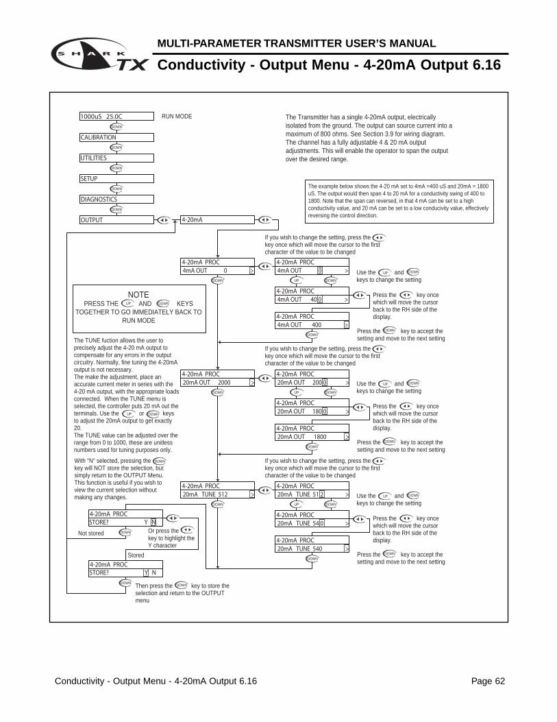
The Transmitter has a single 4-20mA output, electrically isolated from the ground. The output can source current into a maximum of 800 ohms. See Section 3.9 for wiring diagram.The channel has a fully adjustable 4 & 20 mA output adjustments. This will enable the operator to span the output over the desired range.
STORE? Y N
STORE? Y N 4-20mA PROC
20mA TUNE 54 0 >4-20mA PROC
20mA TUNE 54 0 >4-20mA PROC
OUTPUT
CALIBRATION
DIAGNOSTICS
UTILITIES
SETUP
7.15pH 25.0C
4-20mA
20mA TUNE 512 >4-20mA PROC
4-20mA PROC20mA OUT 14.00 >
20mA TUNE 51 2 >
4-20mA PROC
4-20mA PROC
20mA OUT 14.0 0 >
20mA OUT 14.00 >
20mA OUT 14.0 0 >4-20mA PROC
4-20mA PROC
4-20mA PROC
4-20mA PROC4mA OUT 0.00 >
4-20mA PROC
4-20mA PROC
4mA OUT 7.00 >
4mA OUT 7.0 0 >
4-20mA PROC4mA OUT 0.0 0 >
Section 5 - Using the Transmitter in ORP Mode Page 29
MULTI-PARAMETER TRANSMITTER USER’S MANUAL
Section 5 - Using the Transmitter in ORP Mode
SIMPLE THREE-BUTTON INTERFACEFOR FAST & EASY SETUP(REFER TO SECTIONS 5.0 TO 5.13)
2 LINE, 16 CHARACTER LCD DISPLAY
MAIN MENU INTERFACE SCREEN
1/4" TURN SCREWS(FOR SHARKTX ONLY)
UNIT LABELLABEL TO INDICATE UNIT OF MEASURE SHARK IS CONFIGURED FOR.
MULTI-PARAMETER TRANSMITTER USER’S MANUAL
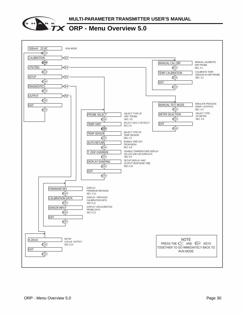
ORP - Menu Overview 5.0
ORP - Menu Overview 5.0 Page 30
DOWN
DOWN
DOWN
DOWN
DOWN
DOWN
DOWN
DOWN
DOWN
DOWN
DOWN
DOWN
DOWNDOWN
DOWN
DOWN
DOWNDOWN
DOWN
DOWN
DOWN
DOWN
DOWN
DOWN
DOWN
SELECT DEG C OR DEG F
ENABLE TIME OUT
ON LCD AND LED DISPLAYSDISABLE TEMPERATURE DISPLAY
SETUP DISPLAY AND OUTPUT RESPONSE TIME
SELECT TYPE OF
FROM MENU
DISPLAYFIRMWAVE REVISIONSEC. 5.11
DISPLAY PREVIOUS CALIBRATION DATASEC 5.12
DISPLAY UNCALIBRATEDPROBE DATASEC 5.13
SEC. 5.8
SELECT TYPE OFTEMP SENSORSEC. 5.7
SEC 5.9
SEC 5.10
SEC. 5.5
SEC 5.6
ORP PROBE
RUN MODE
SEC. 5.2
UP
NOTEPRESS THE AND KEYS
TOGETHER TO GO IMMEDIATELY BACK TO RUN MODE
DOWN
SELECT TYPEOF METERSEC. 5.4
VERIFY OUTPUTSSIMULATE PROCESS
SEC. 5.3
MANUAL CALIBRATE
SENSOR IN ORP PROBECALIBRATE TEMP.
ORP PROBESEC. 5.1
DIAGNOSTICS
EXIT
SENSOR INPUT
CALIBRATION DATA
FIRMWARE REV
EXIT
DISPLAY DAMPING
T. DISP OVERRIDE
EXIT
AUTO RETURN
TEMP SENSOR
TEMP UNIT
PROBE SELECT
500mV 25.0C
UTILITIES
SETUP
CALIBRATION
MANUAL TEST MODE
METER SELECTION
EXIT
EXIT
TEMP CALIBRATION
MANUAL CAL ORP
DOWN
DOWN
DOWN
4-20 mA OUTPUTSETUP
SEC 5.14
EXIT
4-20mA
OUTPUT
ORP - Calibration Menu - Manual Calibrate 5.1 Page 31
MULTI-PARAMETER TRANSMITTER USER’S MANUAL
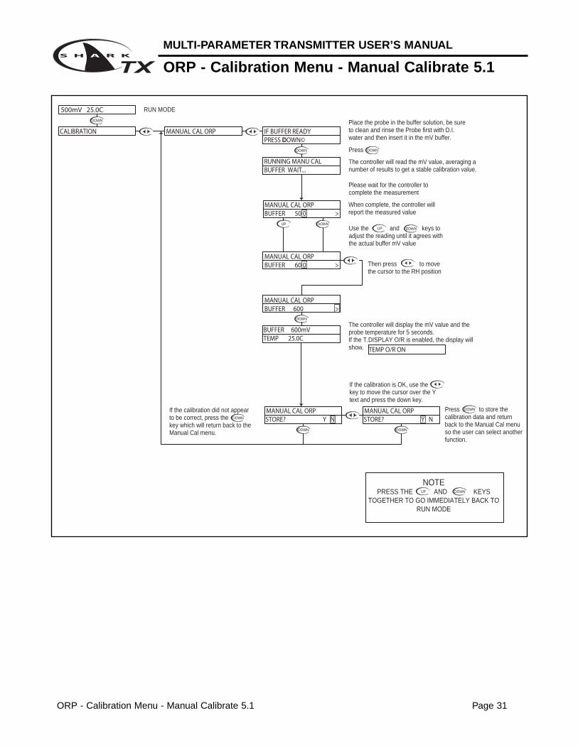
ORP - Calibration Menu - Manual Calibrate 5.1
DOWN
UP
DOWN
DOWN
DOWN
DOWN
UPDOWN
DOWN DOWN
DOWN
DOWN
UP
NOTEPRESS THE AND KEYS
TOGETHER TO GO IMMEDIATELY BACK TO RUN MODE
DOWN
Press to store the calibration data and return back to the Manual Cal menu so the user can select another function.
Place the probe in the buffer solution, be sure to clean and rinse the Probe first with D.I. water and then insert it in the mV buffer.
Press
If the calibration did not appear to be correct, press the key which will return back to the Manual Cal menu.
The controller will display the mV value and the probe temperature for 5 seconds.If the T.DISPLAY O/R is enabled, the display will show.
If the calibration is OK, use the key to move the cursor over the Y text and press the down key.
Then press to move the cursor to the RH position
Use the and keys to adjust the reading until it agrees with the actual buffer mV value
When complete, the controller will report the measured value
Please wait for the controller to complete the measurement
The controller will read the mV value, averaging a number of results to get a stable calibration value.
ORP - Calibration Menu - Temp. Calibration 5.2 Page 32
DOWN
DOWN DOWN
DOWNUP
DOWN
DOWNUP
DOWN
DOWN
DOWN
DOWN
DOWN
If the Temperature Display Override is set to ON (see section 5.10), the Shark cannot calibrate the temperature sensor. This display will appear to alert the user to the condition.
If the calibration did not appear to be correct, press the key which will return back to the Temp Calibration menu.
UP
NOTEPRESS THE AND KEYS
TOGETHER TO GO IMMEDIATELY BACK TO RUN MODE
DOWN
This will store the calibration data and return back to the Temp Calibration setup so the user can select another function.
Use the and to adjust the reading until it agrees with the known temperature of the probe
Press the key to accept the reading and move to the store function
"T FACTOR SHIFTED" will be displayed for 5 seconds to indicate that the temperature sensor has been calibrated. The Shark will then move to the store function.
The controller displays the current probe temperature.If this incorrect, the controller can be adjusted to compensate.
Press the key once which will move the cursor back to the RH side of temperature display.
Press the key once which will move the cursor over the least sign. digit of the temperature display.
RUN MODE
STORE? Y NTEMP CALIBRATION
STORE? Y N TEMP CALIBRATION
TEMP CALIBRATION 25.0C >
T FACTOR SHIFTED
25. 0 C >TEMP CALIBRATION
TEMP CALIBRATION
TEMP CALIBRATION
TEMP CALIBRATION 22. 4 C >
22.4C >
TEMP CALIBRATIONTEMP O/R ON >
500mV 25.0C
CALIBRATION MANUAL CAL ORP
ORP - Utilities Menu - Manual Test Mode 5.3 Page 33
MULTI-PARAMETER TRANSMITTER USER’S MANUAL
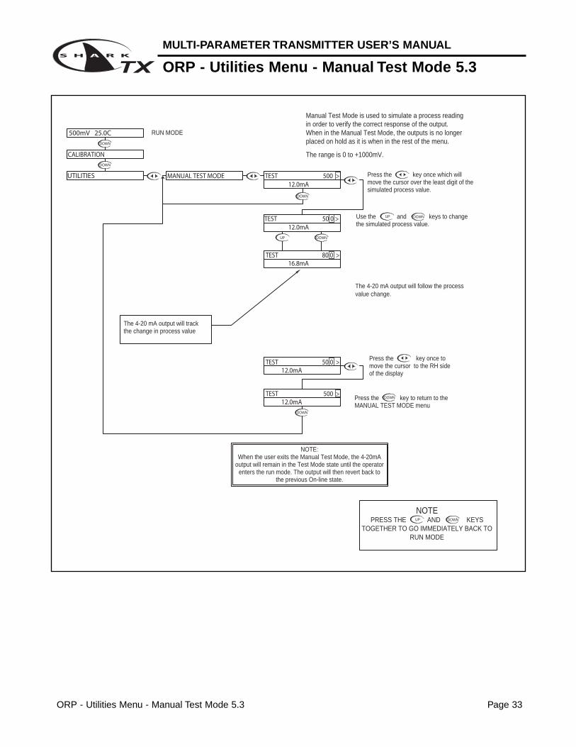
ORP - Utilities Menu - Manual Test Mode 5.3
DOWN
DOWN
DOWN
UP DOWN
DOWN
UP DOWN
Manual Test Mode is used to simulate a process reading in order to verify the correct response of the output. When in the Manual Test Mode, the outputs is no longer placed on hold as it is when in the rest of the menu.
The range is 0 to +1000mV.
NOTE:When the user exits the Manual Test Mode, the 4-20mA
output will remain in the Test Mode state until the operator enters the run mode. The output will then revert back to
the previous On-line state.
The 4-20 mA output will track the change in process value
RUN MODE
UP
NOTEPRESS THE AND KEYS
TOGETHER TO GO IMMEDIATELY BACK TO RUN MODE
DOWN
Press the key once to move the cursor to the RH side of the display
The 4-20 mA output will follow the process value change.
Press the key to return to the MANUAL TEST MODE menu
Use the and keys to change the simulated process value.
Press the key once which will move the cursor over the least digit of the simulated process value.
TEST 50 0 >
TEST 500 >
500mV 25.0C
CALIBRATION
UTILITIES
12.0mA
12.0mA
TEST 50 0 >
TEST 500 >
MANUAL TEST MODE 12.0mA
12.0mA
16.8mATEST 80 0 >
DOWN
MULTI-PARAMETER TRANSMITTER USER’S MANUAL
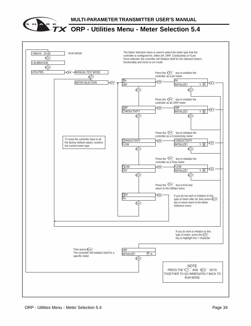
ORP - Utilities Menu - Meter Selection 5.4
ORP - Utilities Menu - Meter Selection 5.4 Page 34
DOWNDOWN
DOWN
DOWN
DOWN
DOWN
DOWN
DOWN
DOWN
DOWN
DOWN
DOWN
DOWN DOWN
DOWN
If you do not wish to initialize to this type of meter after all, then press key to return back to the Meter Selection menu
Then press The controller will initialize itself for a specific meter
If you do wish to initialize to this type of meter, press the key to highlight the Y character
UP
NOTEPRESS THE AND KEYS
TOGETHER TO GO IMMEDIATELY BACK TO RUN MODE
DOWN
Press the key to Exit and return to the Utilities menu
RUN MODE
Press the key to initialize the controller as a Flow meter
Press the key to initialize the controller as a Conductivity meter
The Meter Selection menu is used to select the meter type that the controller is configured for, either pH, ORP, Conductivity or FLow. Once selected, the controller will initialize itself for the selected meter's functionality and move to run mode.
Press the key to initialize the controller as an ORP meter
Press the key to initialize the controller as a pH meter.
INITIALIZE? Y N
INITIALIZE? Y N
INITIALIZE? Y N
INITIALIZE? Y N
INITIALIZE? Y NORP
PHE XIT
MANUAL TEST MODE
500mV 25.0C
UTILITIES
CALIBRATION
METER SELECTION
C ONDUCTIVITYFLOW
EXITF LOW
CONDUCTIVITYO RP
CONDUCTIVITY
FLOW
ORP
P HORP
PH
To reset the controller back to all the factory default values, reselect the current meter type
ORP - Setup Menu - Probe Select 5.5 Page 35
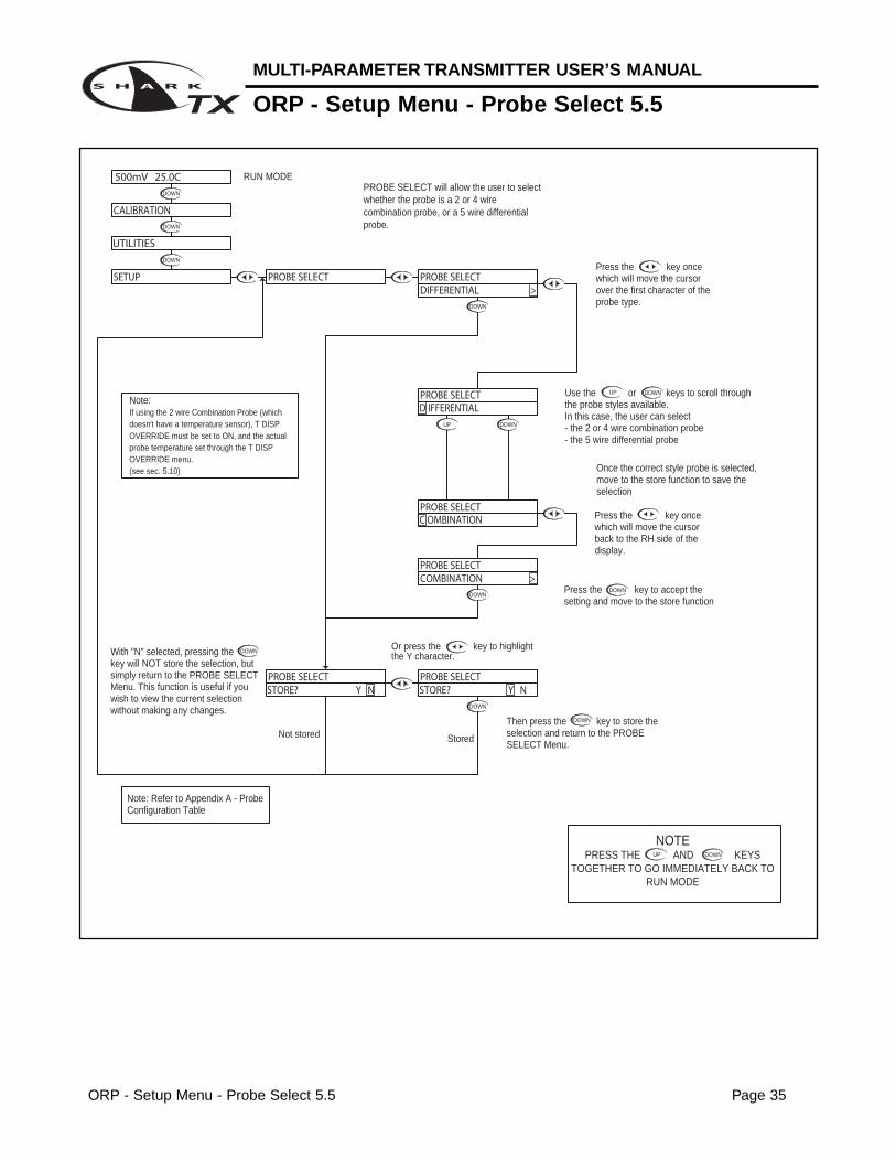
MULTI-PARAMETER TRANSMITTER USER’S MANUAL
ORP - Setup Menu - Probe Select 5.5
DOWN
DOWN
DOWN
DOWN
DOWN
DOWN
UP DOWN
DOWN
DOWN
DOWN
UP DOWN
Then press the key to store the selection and return to the PROBE SELECT Menu.
With "N" selected, pressing the key will NOT store the selection, but simply return to the PROBE SELECT Menu. This function is useful if you wish to view the current selection without making any changes.
Not stored Stored
Or press the key to highlightthe Y character.
Note:If using the 2 wire Combination Probe (which doesn't have a temperature sensor), T DISP OVERRIDE must be set to ON, and the actual probe temperature set through the T DISP OVERRIDE menu.(see sec. 5.10)
PROBE SELECT will allow the user to select whether the probe is a 2 or 4 wire combination probe, or a 5 wire differential probe.
RUN MODE
UP
NOTEPRESS THE AND KEYS
TOGETHER TO GO IMMEDIATELY BACK TO RUN MODE
DOWN
Use the or keys to scroll through the probe styles available. In this case, the user can select - the 2 or 4 wire combination probe- the 5 wire differential probe
Press the key to accept the setting and move to the store function
Press the key once which will move the cursor back to the RH side of the display.
Once the correct style probe is selected, move to the store function to save the selection
Press the key once which will move the cursor over the first character of the probe type.
STORE? Y N STORE? Y N PROBE SELECT PROBE SELECT
500mV 25.0C
UTILITIES
SETUP
CALIBRATION
PROBE SELECTCOMBINATION >
C OMBINATIONPROBE SELECT
D IFFERENTIALPROBE SELECT
PROBE SELECT PROBE SELECTDIFFERENTIAL >
Note: Refer to Appendix A - Probe Configuration Table
MULTI-PARAMETER TRANSMITTER USER’S MANUAL
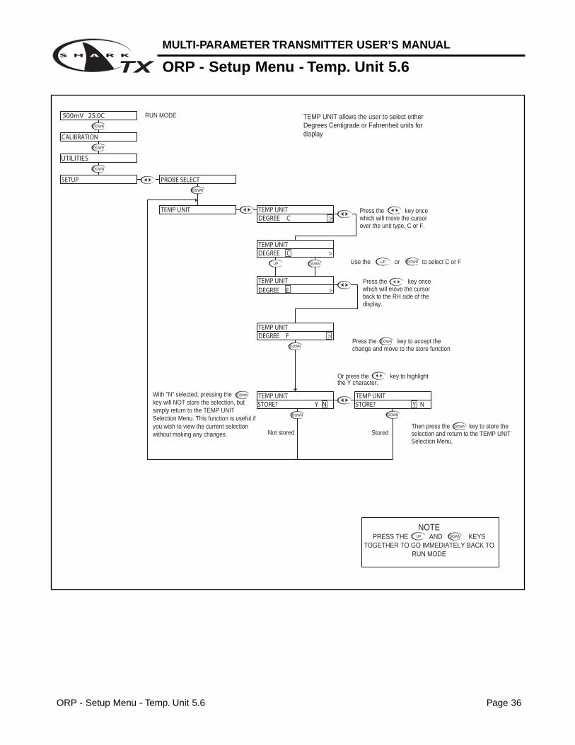
ORP - Setup Menu - Temp. Unit 5.6
ORP - Setup Menu - Temp. Unit 5.6 Page 36
DOWN
DOWN
DOWN
DOWN
DOWN
DOWN DOWN
DOWN
DOWN
UP DOWN
DOWN
UP DOWN
With "N" selected, pressing the key will NOT store the selection, but simply return to the TEMP UNIT Selection Menu. This function is useful if you wish to view the current selection without making any changes.
RUN MODE
Or press the key to highlight
UP
NOTEPRESS THE AND KEYS
TOGETHER TO GO IMMEDIATELY BACK TO RUN MODE
DOWN
Then press the key to store the selection and return to the TEMP UNIT Selection Menu.
Not stored Stored
the Y character.
Use the or to select C or F
Press the key to accept the change and move to the store function
Press the key once which will move the cursor over the unit type, C or F.
Press the key once which will move the cursor back to the RH side of the display.
TEMP UNIT allows the user to select either Degrees Centigrade or Fahrenheit units for display
500mV 25.0C
CALIBRATION
UTILITIES
SETUP
TEMP UNIT
PROBE SELECT
STORE? Y N STORE? Y N TEMP UNIT TEMP UNIT
DEGREE C >
DEGREE F >TEMP UNIT
DEGREE F >
DEGREE C >
TEMP UNIT
TEMP UNIT
TEMP UNIT
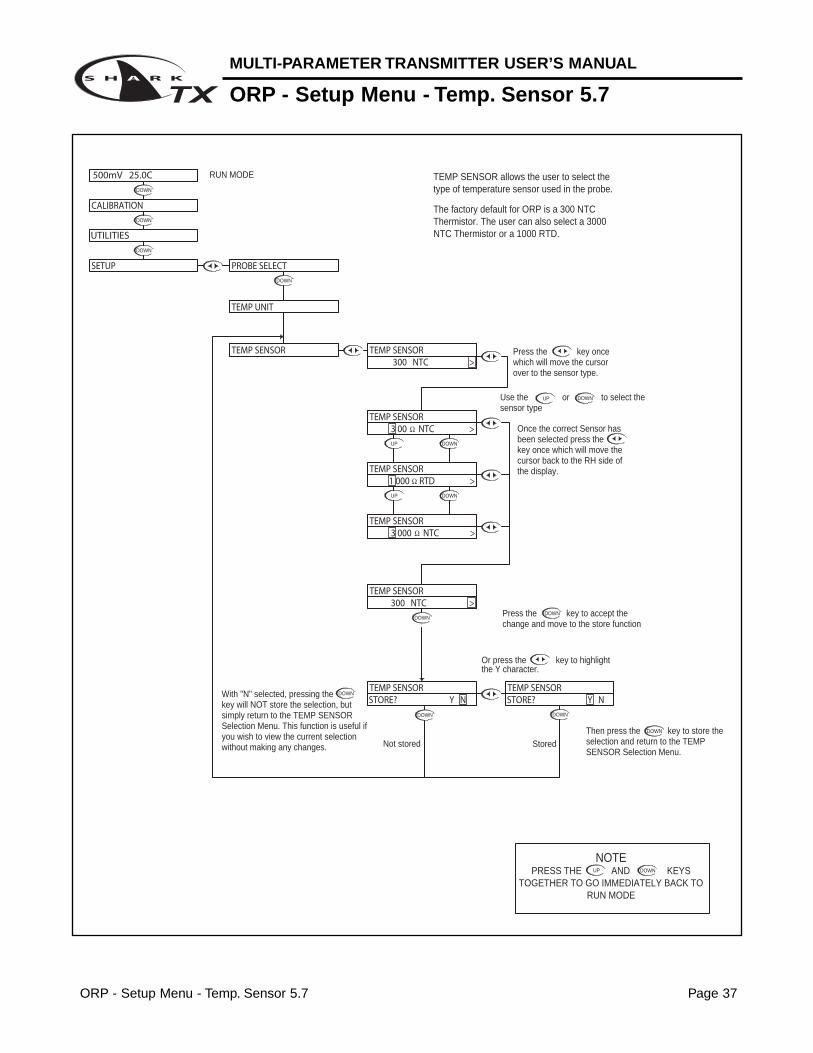
ORP - Setup Menu - Temp. Sensor 5.7 Page 37
MULTI-PARAMETER TRANSMITTER USER’S MANUAL
ORP - Setup Menu - Temp. Sensor 5.7
DOWN
DOWN
DOWN
DOWN
DOWN
DOWN
DOWN
DOWN
DOWN
UP
UP
DOWN
DOWN
DOWN
UP DOWN
the Y character.Or press the key to highlight
With "N" selected, pressing the key will NOT store the selection, but simply return to the TEMP SENSOR Selection Menu. This function is useful if you wish to view the current selection without making any changes. Not stored
UP
NOTEPRESS THE AND KEYS
TOGETHER TO GO IMMEDIATELY BACK TO RUN MODE
DOWN
Press the key to accept the change and move to the store function
Then press the key to store the selection and return to the TEMP SENSOR Selection Menu.
Stored
TEMP SENSOR allows the user to select the type of temperature sensor used in the probe.
The factory default for ORP is a 300 NTC Thermistor. The user can also select a 3000 NTC Thermistor or a 1000 RTD.
RUN MODE
Use the or to select the sensor type
Once the correct Sensor has been selected press the key once which will move the cursor back to the RH side of the display.
Press the key once which will move the cursor over to the sensor type.
500mV 25.0C
SETUP
UTILITIES
CALIBRATION
STORE? Y N STORE? Y N TEMP SENSOR
300 NTC >
3 000 NTC >
TEMP SENSOR
Ω
TEMP SENSOR
TEMP UNIT
TEMP SENSOR
1 000 RTD >
TEMP SENSOR
TEMP SENSOR
3 00 NTC >TEMP SENSOR
Ω
Ω
300 NTC >TEMP SENSOR
PROBE SELECT
MULTI-PARAMETER TRANSMITTER USER’S MANUAL
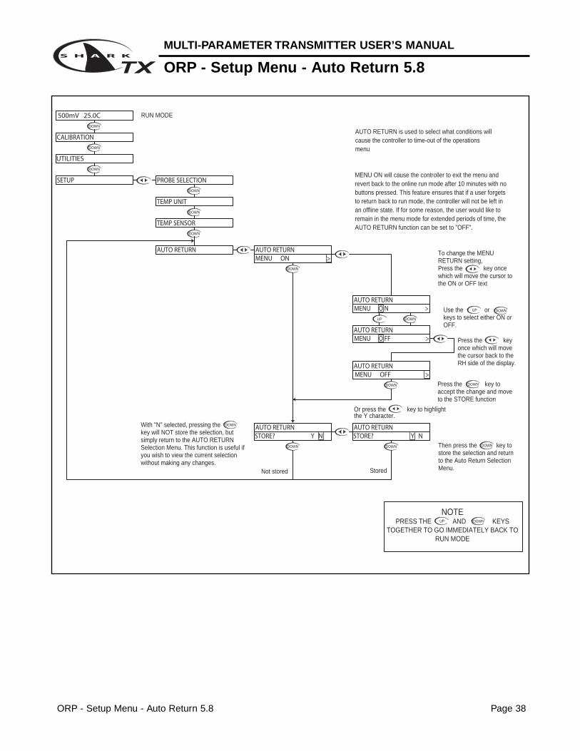
ORP - Setup Menu - Auto Return 5.8
ORP - Setup Menu - Auto Return 5.8 Page 38
DOWN
DOWN
DOWN
DOWN
Not stored
DOWN
Stored
DOWN DOWN
DOWN
DOWN
DOWN
DOWN
DOWN
DOWN
UP DOWN
DOWNUP
UP
NOTEPRESS THE AND KEYS
TOGETHER TO GO IMMEDIATELY BACK TO RUN MODE
DOWN
With "N" selected, pressing the key will NOT store the selection, but simply return to the AUTO RETURN Selection Menu. This function is useful if you wish to view the current selection without making any changes.
Then press the key to store the selection and return to the Auto Return Selection Menu.
Press the key to accept the change and move to the STORE function
Or press the key to highlightthe Y character.
RUN MODE
To change the MENU RETURN setting,Press the key once which will move the cursor to the ON or OFF text
Use the or keys to select either ON or OFF.
Press the key once which will move the cursor back to the RH side of the display.
MENU ON will cause the controller to exit the menu and revert back to the online run mode after 10 minutes with no buttons pressed. This feature ensures that if a user forgets to return back to run mode, the controller will not be left in an offline state. If for some reason, the user would like to remain in the menu mode for extended periods of time, the AUTO RETURN function can be set to "OFF".
AUTO RETURN is used to select what conditions will cause the controller to time-out of the operations menu
Press the key to accept the change and move to the store function
Press the key once which will move the cursor back to the RH side of the display.
Then press the key to store the selection and return to the T. DISP OVERRIDE Menu.
UP
NOTEPRESS THE AND KEYS
TOGETHER TO GO IMMEDIATELY BACK TO RUN MODE
DOWN
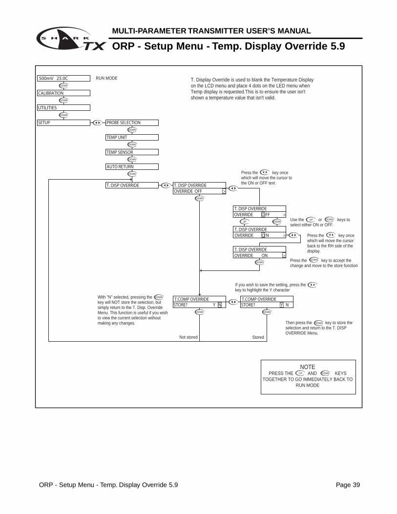
With "N" selected, pressing the key will NOT store the selection, but simply return to the T. Disp. Override Menu. This function is useful if you wish to view the current selection without making any changes.
If you wish to save the setting, press the key to highlight the Y character
Not stored Stored
RUN MODE
Press the key once which will move the cursor to the ON or OFF text
T. Display Override is used to blank the Temperature Display on the LCD menu and place 4 dots on the LED menu when Temp display is requested.This is to ensure the user isn't shown a temperature value that isn't valid.
STORE? Y N STORE? Y N T.COMP OVERRIDE T.COMP OVERRIDE
AUTO RETURN
T. DISP OVERRIDE
CALIBRATION
UTILITIES
SETUP
500mV 25.0C
TEMP UNIT
TEMP SENSOR
PROBE SELECTION
OVERRIDE O FF >
OVERRIDE O N >T. DISP OVERRIDE
T. DISP OVERRIDE
OVERRIDE ON >T. DISP OVERRIDE
OVERRIDE OFF >T. DISP OVERRIDE
MULTI-PARAMETER TRANSMITTER USER’S MANUAL
ORP - Setup Menu - Display Damping 5.10
ORP - Setup Menu - Display Damping 5.10 Page 40
DOWN
DOWN
DOWN
DOWN
DOWN
DOWN
DOWN
DOWN
DOWN
DOWN
DOWN
DOWN
DOWN
DOWN
DOWN
UP
DOWNUP
DOWN
UP
NOTEPRESS THE AND KEYS
TOGETHER TO GO IMMEDIATELY BACK TO RUN MODE
DOWN
The Display Damping menu allows the user to adjust the rate at which the display and the output is updated. This allows the user to dampen out unstable process readings. The damping can be set from 0 seconds to 10 seconds. (default value is 0 sec.)
With "N" selected, pressing the key will NOT store the selection, but simply return to the Display Damping Menu. This function is useful if you wish to view the current selection without making any changes.
Not stored
RUN MODE
Use the and to adjust the damping time, the default setting is 0 seconds.The setting can be adjusted from 0 to 10 seconds.
Then press the key to store the selection and return to the Display Damping Menu.Stored
If you wish to save the setting, press the key to highlight the Y character
Press the key once which will move the cursor back to the RH side of the display.
Press the key to accept the setting and move to the store function
Press the key once which will move the cursor over the seconds digit
STORE? Y N
UPDATE 10 SEC >
UPDATE 0 SEC >
DISPLAY DAMPING
UPDATE 1 0 SEC >
DISPLAY DAMPING
DISPLAY DAMPING
DISPLAY DAMPING
STORE? Y NDISPLAY DAMPING
500mV 25.0C
CALIBRATION
SETUP
UTILITIES
DISPLAY DAMPING
TEMP SENSOR
AUTO RETURN
T. DISP OVERRIDE
DISPLAY DAMPINGUPDATE 0SEC >
TEMP UNIT
PROBE SELECTION
MULTI-PARAMETER TRANSMITTER USER’S MANUAL
ORP - Diagnostics Menu - Firmware Rev 5.11
ORP - Diagnostics Menu - Firmware Rev 5.11 Page 41
DOWN
DOWN
DOWN
DOWN
DOWN
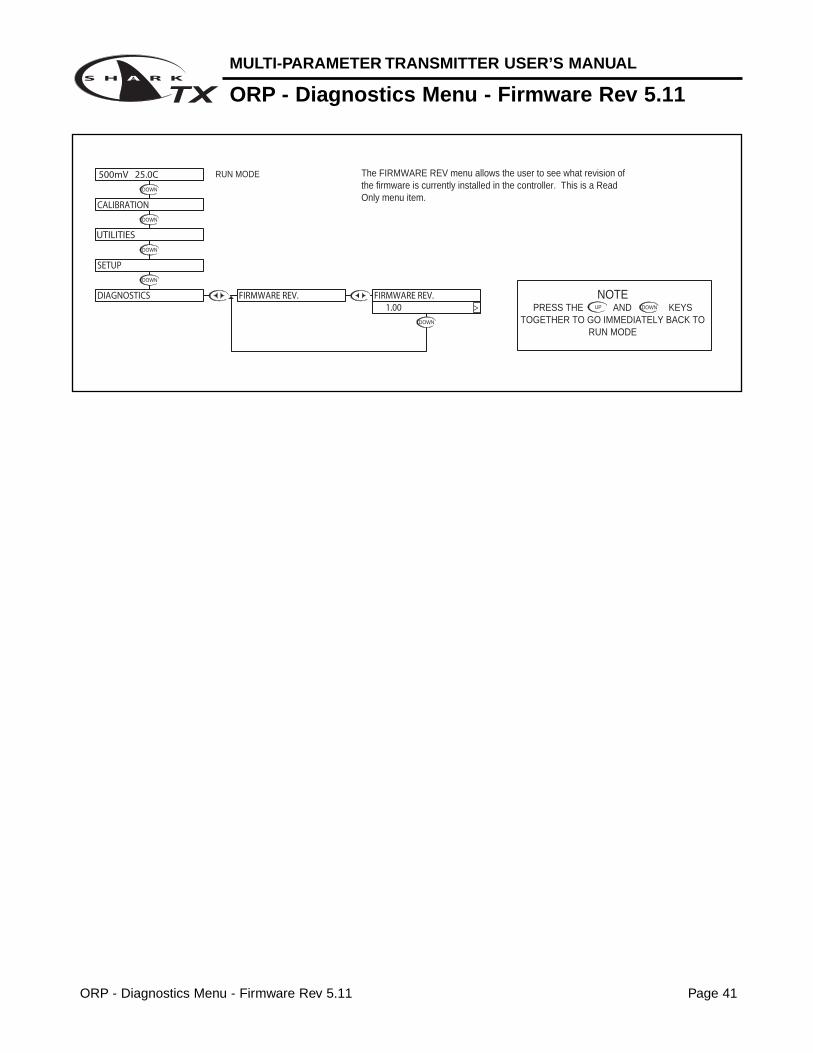
The FIRMWARE REV menu allows the user to see what revision of the firmware is currently installed in the controller. This is a Read Only menu item.
RUN MODE
UP
NOTEPRESS THE AND KEYS
TOGETHER TO GO IMMEDIATELY BACK TO RUN MODE
DOWN
500mV 25.0C
DIAGNOSTICS
SETUP
UTILITIES
CALIBRATION
FIRMWARE REV. FIRMWARE REV. 1.00 >
ORP - Diagnostics Menu - Calibration Data 5.12 Page 42
MULTI-PARAMETER TRANSMITTER USER’S MANUAL
ORP - Diagnostics Menu - Calibration Data 5.12
DOWN
DOWN
DOWN
DOWN
DOWN
DOWN
DOWN
DOWN DOWN
UP
NOTEPRESS THE AND KEYS
TOGETHER TO GO IMMEDIATELY BACK TO RUN MODE
DOWN
The Calibration Data menu is a series of read only screens which allow the user to view the data collected during the last calibration.
RUN MODE
If the Temperature Display Override is ON (Section 5.10), the display will show
Press to view the first Calibration Data screen.
1st POINT 600mV
Probe Temperature at which calibration was performed = 19.4 C
Calibration Mode1 point calibration
Press to view the next Calibration Data screen.
CALIBRATION
UTILITIES
DIAGNOSTICS
SETUP
500mV 25.0C
CALIBRATION DATATEMP O/R ON
CAL TEMP 19.4C >CALIBRATION DATA
CALIBRATION DATA
MODE 1PT >CALIBRATION DATACALIBRATION DATA
FIRMWARE REV.
600mV >
MULTI-PARAMETER TRANSMITTER USER’S MANUAL
ORP - Diagnostics Menu - Sensor Input 5.13
ORP - Diagnostics Menu - Sensor Input 5.13 Page 43
DOWN
DOWN
DOWN
DOWN
DOWN
DOWN
DOWN
UP
NOTEPRESS THE AND KEYS
TOGETHER TO GO IMMEDIATELY BACK TO RUN MODE
DOWN
The Sensor Input Menu allows the user to view real time, uncompensated process data from the probe.This is a Read only menu item.
The top line shows the mV input from the probeThe bottom line shows the actual value of the temperature sensor in ohms.
Press to view the Sensor Input data.
CALIBRATION DATA
SETUP
DIAGNOSTICS
SENSOR INPUT
FIRMWARE REV.
500mV 25.0C
UTILITIES
CALIBRATION
TEMP 331Ω >PROBE 500mV
If the Probe is not equiped with a Temperature Sensing Device, and Temperature Display Override is ON (Section 5.10), the display will show
PROBE 500mVTEMP O/R ON
RUN MODE
ORP - Output Menu - 4-20mA Output 5.14 Page 44
MULTI-PARAMETER TRANSMITTER USER’S MANUAL
ORP - Output Menu - 4-20mA Output 5.14
DOWN
DOWN DOWN
DOWN DOWN
DOWN
UP
DOWN
DOWN
DOWN
DOWN
DOWN
DOWN
DOWN
DOWN
DOWN
UP DOWN
UP DOWN
DOWN
DOWN
UP DOWN
DOWN
DOWNUP
DOWNUP
DOWN
DOWNUP
Press the key once which will move the cursor back to the RH side of the display.
Or press the key to highlight the Y character
Then press the key to store the selection and return to the OUTPUT menu
Not stored
Stored
Press the key to accept the setting and move to the next setting
UP
NOTEPRESS THE AND KEYS
TOGETHER TO GO IMMEDIATELY BACK TO RUN MODE
DOWN
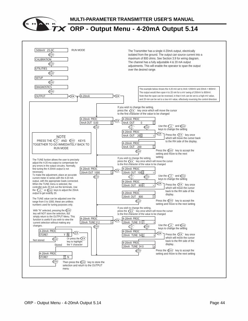
The TUNE fuction allows the user to precisely adjust the 4-20 ma output to compensate for any errors in the output circuitry. Normally, fine tuning the 4-20mA output is not necessary.To make the adjustment, place an accurate current meter in series with the 4-20 mA output, with the appropriate loads connected. When the TUNE menu is selected, the controller puts 20 mA out the terminals. Use the or keys to adjust the 20mA output to get exactly 20.
The TUNE value can be adjusted over the range from 0 to 1000, these are unitless numbers used for tuning purposes only.
RUN MODE
With "N" selected, pressing the key will NOT store the selection, but simply return to the OUTPUT Menu. This function is useful if you wish to view the current selection without making any changes.
The example below shows the 4-20 mA set to 4mA =200mV and 20mA = 800mV.
The output would then span 4 to 20 mA for a mV swing of 200mV to 800mV.
Note that the span can be reversed, in that 4 mA can be set to a high mV value,
and 20 mA can be set to a low mV value, effectively reversing the control direction.
Use the and keys to change the setting
If you wish to change the setting,press the key once which will move the cursor to the first character of the value to be changed
Press the key to accept the setting and move to the next setting
Use the and keys to change the setting
If you wish to change the setting,press the key once which will move the cursor to the first character of the value to be changed
If you wish to change the setting,press the key once which will move the cursor to the first character of the value to be changed
Use the and keys to change the setting
Press the key to accept the setting and move to the next setting
Press the key once which will move the cursor back to the RH side of the display.
Press the key once which will move the cursor back to the RH side of the display.
The Transmitter has a single 4-20mA output, electrically isolated from the ground. The output can source current into a maximum of 800 ohms. See Section 3.9 for wiring diagram.The channel has a fully adjustable 4 & 20 mA output adjustments. This will enable the operator to span the output over the desired range.
STORE? Y N
STORE? Y N 4-20mA PROC
20mA TUNE 54 0 >4-20mA PROC
20mA TUNE 54 0 >4-20mA PROC
OUTPUT
CALIBRATION
DIAGNOSTICS
UTILITIES
SETUP
500mV 25.0C
4-20mA
20mA TUNE 512 >4-20mA PROC
4-20mA PROC20mA OUT 1000 >
20mA TUNE 51 2 >
4-20mA PROC
4-20mA PROC
20mA OUT 80 0 >
20mA OUT 800 >
20mA OUT 100 0 >4-20mA PROC
4-20mA PROC
4-20mA PROC
4-20mA PROC4mA OUT 0.00 >
4-20mA PROC
4-20mA PROC
4mA OUT 200 >
4mA OUT 20 0 >
4-20mA PROC4mA OUT 0 >
Section 6 - Using the Transmitter in Conductivity Mode Page 45
MULTI-PARAMETER TRANSMITTER USER’S MANUAL
Section 6 - Using the Transmitter in Conductivity Mode
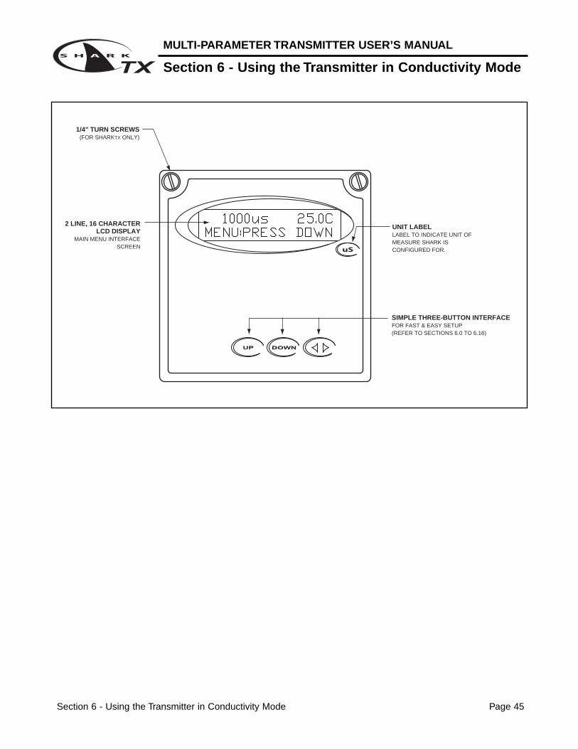
SIMPLE THREE-BUTTON INTERFACEFOR FAST & EASY SETUP(REFER TO SECTIONS 6.0 TO 6.16)
2 LINE, 16 CHARACTER LCD DISPLAY
MAIN MENU INTERFACE SCREEN
1/4" TURN SCREWS(FOR SHARKTX ONLY)
UNIT LABELLABEL TO INDICATE UNIT OF MEASURE SHARK IS CONFIGURED FOR.
MULTI-PARAMETER TRANSMITTER USER’S MANUAL
Conductivity - Menu Overview 6.0
Conductivity - Menu Overview 6.0 Page 46
DOWN
DOWN
DOWN
DOWN
DOWN
DOWN
DOWN
DOWN
DOWN
DOWN
DOWN
DOWNDOWN
DOWN
DOWNDOWN
DOWN
DOWN
DOWNDOWN
DOWN
DOWN
DOWN
DOWN
DOWN
DOWN
DOWN
DOWNDOWN
COMPENSATION VALUE
OUTPUT RESPONSE TIME
SELECT TYPE OF
SELECT DEG C OR DEG F
SELECT MEASURING
ENABLE TIME OUT
FOR PROBE WITHOUT TEMP. SENSORTEMPERATURE SETUP
SETUP DISPLAY AND
SEC 6.15
SEC 6.14
SEC. 6.13
DISPLAYFIRMWAVE REVISION
DISPLAY PREVIOUS CALIBRATION DATA
DISPLAY UNCALIBRATEDPROBE DATA
SEC 6.12
SETUP TEMP
SEC 6.11
SEC 6.10
SEC. 6.6
SEC. 6.9
SEC 6.7
SEC 6.8TEMP SENSOR
FROM MENU
RANGE
RUN MODE
SEC. 6.3
UP
NOTEPRESS THE AND KEYS
TOGETHER TO GO IMMEDIATELY BACK TO RUN MODE
DOWN
VERIFY OUTPUTS
SELECT TYPE
SEC. 6.5
SEC. 6.4
OF METER
SIMULATE PROCESS
SENSOR IN PROBE
MANUFACTURER'S DATACALIBRATE PROBE WITH
CALIBRATE PROBE
CALIBRATE TEMP.
WITH BUFFER SOL'N
SEC. 6.2
SEC. 6.1
DIAGNOSTICS
EXIT
SENSOR INPUT
CALIBRATION DATA
FIRMWARE REV
EXIT
TEMP COMP CURVE
DISPLAY DAMPING
EXIT
AUTO RETURN
TEMP SENSOR
TEMP UNIT
COND. RANGE
T.COMP OVERRIDE
1000uS 25.0C
UTILITIES
SETUP
CALIBRATION
METER SELECTION
MANUAL TEST MODE
EXIT
EXIT
MANUAL CAL COND
TEMP CALIBRATION
DRY CAL COND
DOWN
DOWN
DOWN
4-20 mA OUTPUTSEC 6.16
SETUP
EXIT
4-20mA
OUTPUT
Conductivity - Calibration Menu - Manual Calibrate 6.1 Page 47
MULTI-PARAMETER TRANSMITTER USER’S MANUAL
Conductivity - Calibration Menu - Manual Calibrate 6.1
DOWN
DOWN DOWN
UP DOWN
Manual Calibration is used to "wet calibrate the cell". This can be done with the cell installed in the process, or with the cell suspended in a known buffer solution.When calibrated "In Process", the actual conductivity is determined with a grab sample or a hand held meter, and the value entered in the display.When calibrated with buffers, the cell is placed in a known buffer solution, and the value of the buffer entered on the display.In both cases, make sure the cell has time to stabilize both in temperature and conductivity before entering any data.
If the calibration did not appear to be correct, press the key which will return back to the Manual Cal Cond menu.
DOWN
RUN MODE
UP
NOTEPRESS THE AND KEYS
TOGETHER TO GO IMMEDIATELY BACK TO RUN MODE
DOWN
Place the cell in the buffer solution
Press to store the calibration data and return back to the Manual Cal Cond menu so the user can select another function.
The controller will read the Conductivity value, averaging a number of results to get a stable calibration value.
Use the and keys to adjust the reading until it agrees with the actual buffer conductivityvalue
If the calibration is OK, use the key to move the cursor over the Y text and press the down key.
Then press to move the cursor to the RH position
Press the key once which will move the cursor over the least sign. digit of the display.
UP DOWN
DOWN
CALIBRATION
1000uS 25.0C
MANUAL CAL COND
STORE? Y N STORE? Y N MANUAL CAL COND
MANUAL CAL COND 100 0 uS >
1000 uS >MANUAL CAL COND
MANUAL CAL COND
967 uS >MANUAL CAL COND
96 7 uS >MANUAL CAL COND
MULTI-PARAMETER TRANSMITTER USER’S MANUAL
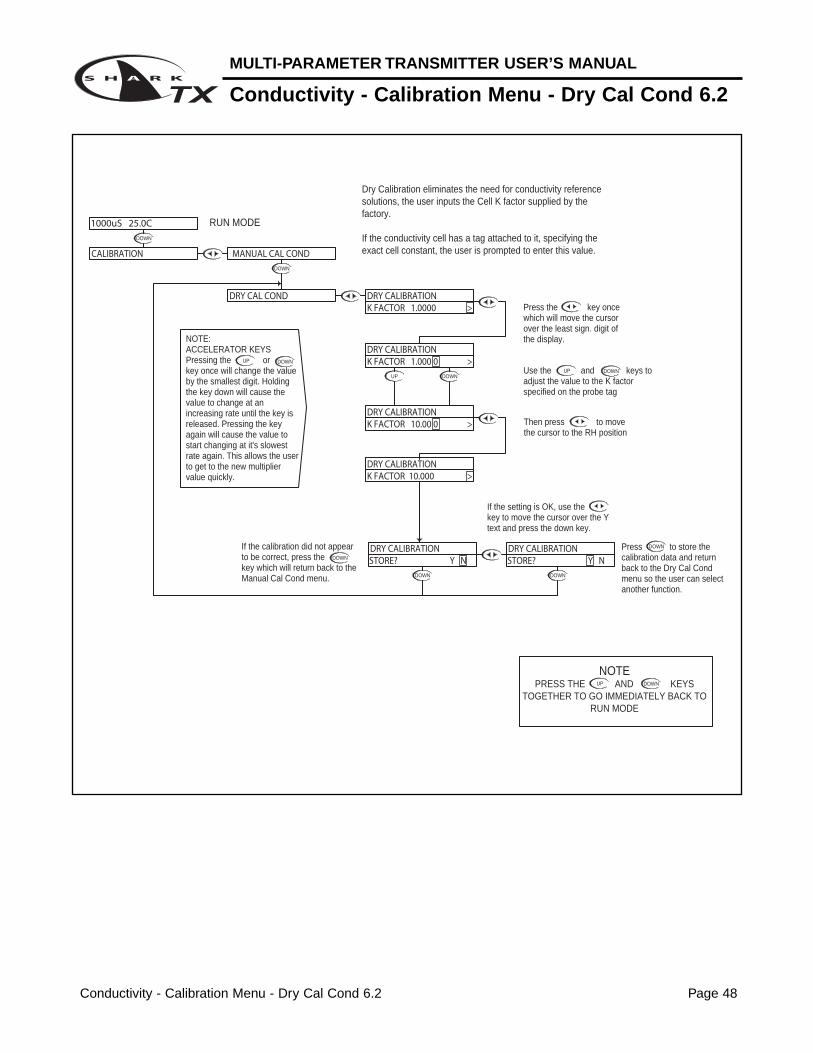
Conductivity - Calibration Menu - Dry Cal Cond 6.2
Conductivity - Calibration Menu - Dry Cal Cond 6.2 Page 48
Dry Calibration eliminates the need for conductivity reference solutions, the user inputs the Cell K factor supplied by the factory.
If the conductivity cell has a tag attached to it, specifying the exact cell constant, the user is prompted to enter this value.
DOWN
DOWN
DOWN
UP
DOWN
DOWN
UP
NOTEPRESS THE AND KEYS
TOGETHER TO GO IMMEDIATELY BACK TO RUN MODE
DOWN
Press to store the calibration data and return back to the Dry Cal Cond menu so the user can select another function.
If the calibration did not appear to be correct, press the key which will return back to the Manual Cal Cond menu.
DOWN
NOTE:ACCELERATOR KEYSPressing the or key once will change the value by the smallest digit. Holding the key down will cause the value to change at an increasing rate until the key is released. Pressing the key again will cause the value to start changing at it's slowest rate again. This allows the user to get to the new multiplier value quickly.
DOWNUP
If the setting is OK, use the key to move the cursor over the Y text and press the down key.
DOWN
UP
Then press to move the cursor to the RH position
Use the and keys to adjust the value to the K factor specified on the probe tag
Press the key once which will move the cursor over the least sign. digit of the display.
DOWN
RUN MODE
CALIBRATION
K FACTOR 10.000 >
K FACTOR 10.00 0 >
DRY CALIBRATION
DRY CALIBRATION
DRY CALIBRATION
STORE? Y N STORE? Y N
K FACTOR 1.000 0 >DRY CALIBRATION
K FACTOR 1.0000 >DRY CALIBRATION
MANUAL CAL COND
DRY CAL COND
DRY CALIBRATION
1000uS 25.0C
Conductivity - Calibration Menu - Temp. Calibration 6.3 Page 49
MULTI-PARAMETER TRANSMITTER USER’S MANUAL
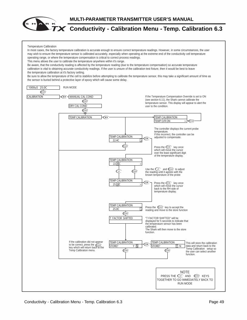
Conductivity - Calibration Menu - Temp. Calibration 6.3
DOWN
DOWN DOWN
DOWNUP
DOWN
DOWN
DOWNUP
DOWN
DOWN
DOWN
If the Temperature Compensation Override is set to ON (see section 6.11), the Shark cannot calibrate the temperature sensor. This display will appear to alert the user to the condition.
If the calibration did not appear to be correct, press the key which will return back to the Temp Calibration menu.
UP
NOTEPRESS THE AND KEYS
TOGETHER TO GO IMMEDIATELY BACK TO RUN MODE
DOWN
This will store the calibration data and return back to the Temp Calibration setup so the user can select another function.
Use the and to adjust the reading until it agrees with the known temperature of the probe
Press the key to accept the reading and move to the store function
"T FACTOR SHIFTED" will be displayed for 5 seconds to indicate that the temperature sensor has been calibrated. The Shark will then move to the store function.
The controller displays the current probe temperature.If this incorrect, the controller can be adjusted to compensate.
Press the key once which will move the cursor back to the RH side of temperature display.
Press the key once which will move the cursor over the least significant digit of the temperature display.
RUN MODE
DRY CAL COND
STORE? Y NTEMP CALIBRATION
STORE? Y N TEMP CALIBRATION
TEMP CALIBRATION 25.0C >
T FACTOR SHIFTED
25. 0 C >TEMP CALIBRATION
TEMP CALIBRATION
TEMP CALIBRATION
TEMP CALIBRATION 22. 4 C >
22.4C >
TEMP CALIBRATIONTEMP O/R ON >
1000uS 25.0C
CALIBRATION MANUAL CAL COND
DOWN
DOWN
Temperature CalibrationIn most cases, the factory temperature calibration is accurate enough to ensure correct temperature readings. However, in some circumstances, the user may wish to ensure the temperature sensor is calibrated accurately, especially when operating at the extreme end of the conductivity cell temperature operating range, or where the temperature compensation is critical to correct process readings.This menu allows the user to calibrate the temperature anywhere within it's range. Be aware, that the conductivity reading is affected by the temperature reading (due to the temperature compensation) so accurate temperature calibration is vital to obtaining accurate conductivity readings. If the user is unsure of the calibration test fixture, then it would be best to leave the temperature calibration at it's factory setting.Be sure to allow the temperature of the cell to stabilize before attempting to calibrate the temperature sensor, this may take a significant amount of time as the sensor is buried behind a protective layer of epoxy which will cause some delay.
MULTI-PARAMETER TRANSMITTER USER’S MANUAL
Conductivity - Utilities Menu - Manual Test Mode 6.4
Conductivity - Utilities Menu - Manual Test Mode 6.4 Page 50
DOWN
DOWN
DOWN
UP DOWN
DOWN
UP DOWN
Manual Test Mode is used to simulate a process reading in order to verify the correct response of the output. When in the Manual Test Mode, the output is no longer placed on hold as it is when in the rest of the menu.
NOTE:When the user exits the Manual Test Mode, the 4-20mA
output will remain in the Test Mode state until the operator enters the run mode. The output will then revert back to the
previous On-line state.
The 4-20 mA output will track the change in process value
RUN MODE
UP
NOTEPRESS THE AND KEYS
TOGETHER TO GO IMMEDIATELY BACK TO RUN MODE
DOWN
Press the key once to move the cursor to the RH side of the display
The 4-20 mA output will follow the process value change.
Press the key to return to the MANUAL TEST MODE menu
Use the and keys to change the simulated process value.
Press the key once which will move the cursor over the least digit of the simulated process value.
TEST 100 0 >
TEST 1000 >
1000uS 25.0C
CALIBRATION
UTILITIES
14.4mATEST 1310 >
TEST 131 0 > 14.4mA
MANUAL TEST MODE 12.0mA
14.4mATEST 131 0 >
12.0mA
DOWN
Conductivity - Utilities Menu - Meter Selection 6.5 Page 51
MULTI-PARAMETER TRANSMITTER USER’S MANUAL
Conductivity - Utilities Menu - Meter Selection 6.5
DOWNDOWN
DOWN
DOWN
DOWN
DOWN
DOWN
DOWN
DOWN
DOWN
DOWN
DOWN
DOWN DOWN
DOWN
Then press The controller will initialize itself for a specific meter
If you do wish to initialize to this type of meter, press the key to highlight the Y character
If you do not wish to initialize to this type of meter after all, then press key to return back to the Meter Selection menu
UP
NOTEPRESS THE AND KEYS
TOGETHER TO GO IMMEDIATELY BACK TO RUN MODE
DOWN
Press the key to Exit and return to the Utilities menu
RUN MODE
Press the key to initialize the controller as a Flow meter
Press the key to initialize the controller as a Conductivity meter
The Meter Selection menu is used to select the meter type that the controller is configured for, either pH, ORP, Conductivity or Flow. Once selected, the controller will initialize itself for the selected meter's functionality and move to run mode.
Press the key to initialize the controller as an ORP meter
Press the key to initialize the controller as a pH meter.
INITIALIZE? Y N
INITIALIZE? Y N
INITIALIZE? Y N
INITIALIZE? Y N
INITIALIZE? Y NCONDUCTIVITY
PHE XIT
MANUAL TEST MODE
1000uS 25.0C
UTILITIES
CALIBRATION
METER SELECTION
C ONDUCTIVITYFLOW
EXITF LOW
EXITO RP
CONDUCTIVITY
FLOW
ORP
P HORP
PH
To reset the controller back to all the factory default values, reselect the current meter type
MULTI-PARAMETER TRANSMITTER USER’S MANUAL
Conductivity - Setup Menu - Conductivity Range 6.6
Conductivity - Setup Menu - Conductivity Range 6.6 Page 52
UP DOWN
DOWN
DOWN
UP
UP
DOWN
DOWN
DOWN
DOWN
DOWN
DOWNUP
UP DOWN
UP DOWN
DOWN
DOWN
DOWN
UP DOWN
Conductivity Range will allow the user to select the measuring range of the instrument. The ranges can be selected from any of the following: 200 mS/cm - cell constant 50 20 mS/cm - cell constant 105000 uS/cm - cell constant 1
With "N" selected, pressing the key will NOT store the selection, but simply return to the COND RANGE Menu. This function is useful if you wish to view the current selection without making any changes.
Not stored
RUN MODE
UP
NOTEPRESS THE AND KEYS
TOGETHER TO GO IMMEDIATELY BACK TO RUN MODE
DOWN
Then press the key to store the selection and return to the COND RANGE Menu.
Stored
Or press the key to highlightthe Y character.
Press the key to accept the setting and move to the store function
Once the correct range is selected, move to the store function to save the selection
Press the key once which will move the cursor back to the RH side of the display.
Use the or keys to scroll through the available ranges
Press the key once which will move the cursor over the last character of the range.
STORE? Y N STORE? Y N COND. RANGE
COND. RANGE
20.00mS/cm >COND. RANGE
20.0 0 mS/cm >
200. 0 mS/cm >
19.9 9 Mo/cm >
COND. RANGE
COND. RANGE
1000uS 25.0C
CALIBRATION
SETUP
UTILITIES
20.0 0 uS/cm >
COND. RANGE
COND. RANGE
2.0 0 uS/cm >
200. 0 uS/cm >COND. RANGE
COND. RANGE500 0 uS/cm >
COND. RANGE COND. RANGE5000uS/cm >
COND. RANGE
Conductivity - Setup Menu - Temp. Unit 6.7 Page 53
MULTI-PARAMETER TRANSMITTER USER’S MANUAL
Conductivity - Setup Menu - Temp. Unit 6.7
DOWN
DOWN
DOWN
DOWN
DOWN DOWN
DOWN
DOWN
UP DOWN
DOWN
DOWN
UP DOWN
With "N" selected, pressing the key will NOT store the selection, but simply return to the TEMP UNIT Selection Menu. This function is useful if you wish to view the current selection without making any changes. Not stored
UP
NOTEPRESS THE AND KEYS
TOGETHER TO GO IMMEDIATELY BACK TO RUN MODE
DOWN
Then press the key to store the selection and return to the TEMP UNIT Selection Menu.
Stored
Or press the key to highlightthe Y character.
TEMP UNIT allows the user to select either Degrees Centigrade or Fahrenheit units for display
RUN MODE
Press the key once which will move the cursor over the unit type, C or F.
Use the or to select C or F
Press the key to accept the change and move to the store function
Press the key once which will move the cursor back to the RH side of the display.
1000uS 25.0C
UTILITIES
SETUP
CALIBRATION
STORE? Y N STORE? Y N TEMP UNIT TEMP UNIT
DEG C >
DEG F >
DEG F >
DEG C >
TEMP UNIT TEMP UNIT
TEMP UNIT
TEMP UNIT
TEMP UNIT
COND RANGE
MULTI-PARAMETER TRANSMITTER USER’S MANUAL
Conductivity - Setup Menu - Temp. Sensor 6.8
Conductivity - Setup Menu - Temp. Sensor 6.8 Page 54
DOWN
DOWN
DOWN
DOWN
DOWN
DOWN
DOWN
DOWN
DOWN
DOWN
UP
UP
DOWN
DOWN
UP DOWN
With "N" selected, pressing the key will NOT store the selection, but simply return to the TEMP SENSOR Selection Menu. This function is useful if you wish to view the current selection without making any changes.
RUN MODE
Then press the key to store the selection and return to the TEMP SENSOR Selection Menu.
Press the key to accept the change and move to the store function
UP
NOTEPRESS THE AND KEYS
TOGETHER TO GO IMMEDIATELY BACK TO RUN MODE
DOWN
Not stored Stored
Or press the key to highlightthe Y character.
Press the key once which will move the cursor over to the sensor type.
Once the correct Sensor has been selected press the key once which will move the cursor back to the RH side of the display.
Use the or to select the sensor type
TEMP SENSOR allows the user to select the type of temperature sensor used the in the probe.The factory default for Conductivity is a 3000 Ω NTC thermistor. The user can also select a 300 Ω NTC thermistor or a Pt. 1000 RTD.
TEMP SENSOR
1000uS 25.0C
CALIBRATION
UTILITIES
SETUP COND RANGE
TEMP UNIT
STORE? Y N STORE? Y N
3 00 NTC >
TEMP SENSOR
TEMP SENSOR
TEMP SENSOR
3000 NTC >
3 000 NTC >
1 000 RTD >
3000 NTC >
Ω
TEMP SENSOR
TEMP SENSORΩ
Ω
TEMP SENSOR
TEMP SENSOR
Ω
Ω
Conductivity - Setup Menu - Auto Return 6.9 Page 55
MULTI-PARAMETER TRANSMITTER USER’S MANUAL
Conductivity - Setup Menu - Auto Return 6.9
DOWN
Not stored
DOWN
Stored
DOWN
DOWN
DOWN
DOWN
DOWN
DOWN
DOWN
DOWN
DOWN
UP DOWN
DOWN
DOWN
DOWNUP
UP
NOTEPRESS THE AND KEYS
TOGETHER TO GO IMMEDIATELY BACK TO RUN MODE
DOWN
Then press the key to store the selection and return to the Auto Return Selection Menu.
Press the key to accept the change and move to the STORE function
To change the MENU RETURN setting,Press the key once which will move the cursor to the ON or OFF text
MENU ON will cause the controller to exit the menu and revert back to the online run mode after 10 minutes with no buttons pressed. This feature ensures that if a user forgets to return back to run mode, the controller will not be left in an offline state. If for some reason, the user would like to remain in the menu mode for extended periods of time, the AUTO RETURN function can be set to "OFF".
AUTO RETURN is used to select what conditions will cause the controller to time-out of the operations menu
With "N" selected, pressing the key will NOT store the selection, but simply return to the AUTO RETURN Selection Menu. This function is useful if you wish to view the current selection without making any changes.
Or press the key to highlightthe Y character.
RUN MODE
Use the or keys to select either ON or OFF.
Press the key once which will move the cursor back to the RH side of the display.
MENU O FF >
MENU O N >
STORE? Y N STORE? Y N AUTO RETURN AUTO RETURN
AUTO RETURN
UTILITIES
SETUP
1000uS 25.0C
CALIBRATION
TEMP SENSOR
TEMP UNIT
COND RANGE
AUTO RETURNMENU ON >
AUTO RETURN
MENU OFF >AUTO RETURN
AUTO RETURN
MULTI-PARAMETER TRANSMITTER USER’S MANUAL
Conductivity - Setup Menu - T. Comp Override 6.10
Conductivity - Setup Menu - T. Comp Override 6.10 Page 56
DOWN
DOWN
DOWN
DOWN
DOWN
DOWN
DOWN
DOWN
DOWN
DOWN
DOWN
DOWN
DOWN
DOWN
DOWN
UP
DOWN
DOWNUP
DOWN
DOWN
UPDOWNUP
DOWN
Not stored Stored
If you wish to save the setting, press the key to highlight the Y character
Temperature Compensation Override is used to manually set the actual probe or process temperature. This is useful if the probe does not have a temperature sensor or if the process temperature is constant. When the override is enabled, the controller will use the selected temperature when performing temperature compensation calculations.
UP
NOTEPRESS THE AND KEYS
TOGETHER TO GO IMMEDIATELY BACK TO RUN MODE
DOWN
With "N" selected, pressing the key will NOT store the selection, but simply return to the T. Comp Override Menu. This function is useful if you wish to view the current selection without making any changes.
RUN MODE
Press the key to accept the reading and move to the store function
Press the key once which will move the cursor back to the RH side of temperature display.
Then press the key to store the selection and return to the T. COMP OVERRIDE Menu.
Press the key to accept the change and move to the Temperature Entry function
Press the key once which will move the cursor over the least significant digit of the temperature display.
Use the and to adjust the reading until it agrees with the known temperature of the probe or process
The user can now enter the actual probe or process temperature
Use the or keys to select either ON or OFF.
Press the key once which will move the cursor back to the RH side of the
Press the key once which will move the cursor to the ON or OFF text
STORE? Y N STORE? Y N
TEMP 35. 7 C >
TEMP 25. 4 C >
COMPENSATE O FF >
COMPENSATE O N >T.COMP OVERRIDE
T.COMP OVERRIDE
COMPENSATE ON >T.COMP OVERRIDE
T.COMP OVERRIDE
T.COMP OVERRIDE
T.COMP OVERRIDETEMP 25.4C >
TEMP 35.7C >T.COMP OVERRIDE
T.COMP OVERRIDE
CALIBRATION
UTILITIES
SETUP
1000uS 25.0C
AUTO RETURN
TEMP SENSOR
T.COMP OVERRIDECOMPENSATE OFF >T.COMP OVERRIDE
TEMP UNIT
COND RANGE
T.COMP OVERRIDE
Conductivity - Setup Menu - Display Damping 6.11 Page 57
MULTI-PARAMETER TRANSMITTER USER’S MANUAL
Conductivity - Setup Menu - Display Damping 6.11
DOWN
DOWN
DOWN
DOWN
DOWN
DOWN
DOWN
DOWN
DOWN
DOWN
DOWN
DOWN
DOWN
DOWN
UP
DOWN
DOWNUP
DOWN
With "N" selected, pressing the key will NOT store the selection, but simply return to the Display Damping Menu. This function is useful if you wish to view the current selection without making any changes.
RUN MODE
UP
NOTEPRESS THE AND KEYS
TOGETHER TO GO IMMEDIATELY BACK TO RUN MODE
DOWN
Use the and to adjust the damping time, the default setting is 0 seconds.The setting can be adjusted from 0 to 10 seconds.
If you wish to save the setting, press the key to highlight the Y character
Then press the key to store the selection and return to the Display Damping Menu.
Press the key once which will move the cursor back to the RH side of the display.
Press the key to accept the setting and move to the store function
Not stored Stored
The Display Damping menu allows the user to adjust the rate at which the display and the output is updated. This allows the user to dampen out unstable process readings. The damping can be set from 0 seconds to 10 seconds. (default value is 0 sec.)
Press the key once which will move the cursor over the seconds digit
DISPLAY DAMPING
TEMP SENSOR
AUTO RETURN
T.COMP OVERRIDE
1000uS 25.0C
CALIBRATION
SETUP
UTILITIES
TEMP UNIT
COND RANGE
STORE? Y N DISPLAY DAMPING
UPDATE 10 SEC >
UPDATE 1 0 SEC >
DISPLAY DAMPING
DISPLAY DAMPING
STORE? Y NDISPLAY DAMPING
UPDATE 0 SEC > DISPLAY DAMPING
DISPLAY DAMPINGUPDATE 0 SEC >
MULTI-PARAMETER TRANSMITTER USER’S MANUAL
Conductivity - Setup Menu - Temp. Comp. Curve 6.12
With "N" selected, pressing the key will NOT store the selection, but simply return to the Temp Cond Curve setting menu. This function is useful if you wish to view the current selection without making any changes.
Not storedThen press the key to store the selection and return to Temp Cond Curve settting menu.
Stored
Press the key to accept the setting and move to the store function
Use the and to adjust the percent compensation.The setting can be changed from 0%/C to 10%/C
If you wish to save the setting, press the key to highlight the Y character
Press the key once which will move the cursor back to the RH side of the display.
The Temperature Compensation Curve setting allows the user to select the temperature compensation to match a specific process.The variation of Conductivity versus Temperature is dependent on the type of solids and liquids in water, so no fixed compensation value will accurately compensate every process. This setting allows the user to fine tune the compensation to their specific process.Estimates of the correct compensation for certain chemicals are available and can be preset via this menu, otherwise the user will need to set the compensation to 0%/C, measure the effect of temperature for a specific process, calculate the actual compensation required and enter it through this menu. The Compensation can be varied from 0%/C to 10%/C.
RUN MODE
Press the key once which will move the cursor over the least digit
1000uS 25.0C
UTILITIES
SETUP
CALIBRATION
2. 0 %/C >
TEMP COMP CURVESTORE? Y N
2.5%/C >
TEMP COMP CURVESTORE? Y N
TEMP COMP CURVE
TEMP COMP CURVE 2. 5 %/C >
TEMP COMP CURVE
DISPLAY DAMPING
T.COMP OVERRIDE
AUTO RETURN
TEMP SENSOR
TEMP COMP CURVE
TEMP COMP CURVE 2.0%/C >
COND RANGE
TEMP UNIT
Conductivity - Diagnostics Menu - Firmware Rev. 6.13 Page 59
MULTI-PARAMETER TRANSMITTER USER’S MANUAL
Conductivity - Diagnostics Menu - Firmware Rev. 6.13
DOWN
DOWN
DOWN
DOWN
DOWN
RUN MODE
NOTEPRESS THE AND KEYS
TOGETHER TO GO IMMEDIATELY BACK TO RUN MODE
The FIRMWARE REV menu allows the user to see what revision of the firmware is currently installed in the controller. This is a Read Only menu item.
UP DOWN
DIAGNOSTICS
SETUP
FIRMWARE REV.
1000uS 25.0C
UTILITIES
CALIBRATION
FIRMWARE REV. 1.00 >
MULTI-PARAMETER TRANSMITTER USER’S MANUAL
Conductivity - Diagnostics Menu - Calibration Data 6.14
Conductivity - Diagnostics Menu - Calibration Data 6.14 Page 60
DOWN
DOWN
DOWN
DOWN
DOWN
DOWN
DOWN
DOWN
DOWN
DOWN
DOWN
DOWN
DOWN
DOWN
DOWN
RUN MODE
UP
NOTEPRESS THE AND KEYS
TOGETHER TO GO IMMEDIATELY BACK TO RUN MODE
DOWN
The Calibration Data menu is a series of read only screens which allow the user to view the data collected during the last calibration.
Calibration Mode1 point calibration
Probe Temperature at which calibration was performed = 25.2° C
Calculated Cell Constant
Conductivity of Buffer/Input Resistance
Press to view the next Calibration Data screen.
Press to view the first Calibration Data screen.
TYPICAL DISPLAYSFOR MANUAL CAL
Calibration ModeDry Cal
Dry Cal does not use a buffer, so Probe Temperature wasnot recorded
Cell Constant Setting
No Buffer used in this Calibration Mode
Press to view the next Calibration Data screen.
TYPCIAL DISPLAYSFOR DRY CAL
CALIBRATION DATA
CALIBRATION DATA
CALIBRATION DATA
CALIBRATION DATA
CALIBRATION DATA
CAL TEMP 25.2C >
K FACTOR 0.9774 >
1P 1000/1000 >
MODE 1PT >
Ω
DIAGNOSTICS
CALIBRATION
UTILITIES
SETUP
FIRMWARE REV.
1000uS 25.0C
CALIBRATION DATA
CAL TEMP - - - - >
K FACTOR 1.0000 >
CALIBRATION DATA
1P - - - - >
MODE DRY >
CALIBRATION DATA
CALIBRATION DATA
Conductivity - Diagnostics Menu - Sensor Input 6.15 Page 61
MULTI-PARAMETER TRANSMITTER USER’S MANUAL
Conductivity - Diagnostics Menu - Sensor Input 6.15
DOWN
DOWN
DOWN
DOWN
DOWN
DOWN
DOWN
UP
NOTEPRESS THE AND KEYS
TOGETHER TO GO IMMEDIATELY BACK TO RUN MODE
DOWN
Press to view the Sensor Input data.
The Sensor Input Menu allows the user to view real time, uncompensated process data from the conductivity cell.This is a Read only menu item.This "Live Data" screen is useful for trouble shooting purposes when diagnosing cell or process problems.
The top line shows the resistance of the cell,The bottom line shows the actual value of the temperature sensor in ohms.
RUN MODE1000uS 25.0C
DIAGNOSTICS
UTILITIES
CALIBRATION
SETUP
CELL 966TEMP 2953 >
SENSOR INPUT
FIRMWARE REV.
CALIBRATION DATA
ΩΩ
MULTI-PARAMETER TRANSMITTER USER’S MANUAL
Conductivity - Output Menu - 4-20mA Output 6.16
Conductivity - Output Menu - 4-20mA Output 6.16 Page 62
DOWN
DOWNDOWN
DOWN
DOWN
UP
DOWN
DOWN
DOWN
DOWN
DOWN
DOWN
DOWN
DOWN
DOWN
UP DOWN
UP DOWN
DOWN
DOWN
UP DOWN
DOWN
DOWNUP
DOWN
DOWNUP
DOWN
DOWNUP
Or press the key to highlight the Y character
Then press the key to store the selection and return to the OUTPUT menu
Not stored
Stored
NOTEPRESS THE AND KEYS
TOGETHER TO GO IMMEDIATELY BACK TO RUN MODE
UP DOWN
The TUNE fuction allows the user to precisely adjust the 4-20 mA output to compensate for any errors in the output circuitry. Normally, fine tuning the 4-20mA output is not necessary.The make the adjustment, place an accurate current meter in series with the 4-20 mA output, with the appropriate loads connected. When the TUNE menu is selected, the controller puts 20 mA out the terminals. Use the or keys to adjust the 20mA output to get exactly 20.The TUNE value can be adjusted over the range from 0 to 1000, these are unitless numbers used for tuning purposes only.
RUN MODE
With "N" selected, pressing the key will NOT store the selection, but simply return to the OUTPUT Menu. This function is useful if you wish to view the current selection without making any changes.
The example below shows the 4-20 mA set to 4mA =400 uS and 20mA = 1800 uS. The output would then span 4 to 20 mA for a conductivity swing of 400 to 1800. Note that the span can reversed, in that 4 mA can be set to a high conductivity value, and 20 mA can be set to a low conducivity value, effectively reversing the control direction.
If you wish to change the setting, press the key once which will move the cursor to the first character of the value to be changed
Use the and keys to change the setting
Press the key to accept the setting and move to the next setting
Press the key once which will move the cursor back to the RH side of the display.
STORE? Y N
STORE? Y N 4-20mA PROC
20mA TUNE 540 >
20mA TUNE 54 0 >
4-20mA PROC
4-20mA PROC
OUTPUT
CALIBRATION
DIAGNOSTICS
UTILITIES
SETUP
1000uS 25.0C
4-20mA
20mA TUNE 512 >4-20mA PROC
4-20mA PROC20mA OUT 2000 >
20mA TUNE 51 2 >
4-20mA PROC
4-20mA PROC
20mA OUT 180 0 >
20mA OUT 1800 >
20mA OUT 200 0 >4-20mA PROC
4-20mA PROC
4-20mA PROC
4-20mA PROC4mA OUT 0 >
4-20mA PROC
4-20mA PROC
4mA OUT 400 >
4mA OUT 40 0 >
4-20mA PROC4mA OUT 0 >
The Transmitter has a single 4-20mA output, electrically isolated from the ground. The output can source current into a maximum of 800 ohms. See Section 3.9 for wiring diagram.The channel has a fully adjustable 4 & 20 mA output adjustments. This will enable the operator to span the output over the desired range.
MULTI-PARAMETER TRANSMITTER USER’S MANUAL
Section 7 - Using the Transmitter in Flow Mode
Section 7 - Using the Transmitter in Flow Mode Page 63
SIMPLE THREE-BUTTON INTERFACEFOR FAST & EASY SETUP(REFER TO SECTIONS 7.0 TO 7.14)
2 LINE, 16 CHARACTER LCD DISPLAY
MAIN MENU INTERFACE SCREEN
1/4" TURN SCREWS(FOR SHARKTX ONLY)
UNIT LABELLABEL TO INDICATE UNIT OF MEASURE SHARK IS CONFIGURED FOR.
Flow - Menu Overview 7.0 Page 64
MULTI-PARAMETER TRANSMITTER USER’S MANUAL
Flow - Menu Overview 7.0
DOWN
DOWN
DOWN
DOWN
DOWN
DOWN
DOWN
DOWN
DOWN
DOWN
DOWNDOWN
DOWN
DOWN
DOWN
DOWN
DOWN
DOWNDOWN
DOWNDOWN
DOWN
DOWN
DOWN
DOWN
DOWNDOWN
ROLLOVERS TO DATEDISPLAY TOTALIZER
TOTALIZERDISPLAY PERMANENT
SENSOR INPUTDISPLAY UNCALIBRATED
CALIBRATION DATADISPLAY PREVIOUS
FIRMWAVE REVISION
SEC 7.13
SEC 7.12
SEC 7.10
SEC 7.11
DISPLAY
SEC 7.9
RUN MODE
UP
NOTEPRESS THE AND KEYS
TOGETHER TO GO IMMEDIATELY BACK TO RUN MODE
DOWN
TO ZEROSEC 7.8
RESET TOTALIZER
SETUP DISPLAY AND OUTPUT RESPONSE TIME
ENABLE TIME OUT
SETUP OF UNITS
SETUP OF UNITS
SEC. 7.4
SEC 7.7
SEC. 7.6FROM MENU
OF TIMESEC. 7.5
OF VOLUME
OF METERSELECT TYPE
SEC. 7.3
VERIFY OUTPUTSSIMULATE PROCESS
SEC. 7.2
CALIBRATION FACTORSEC. 7.1
ENTER FLOW SENSOR
TOTALIZER RESET
AUTO RETURN
DISPLAY DAMPING
UNITS OF TIME
UNITS OF VOLUME
DIAGNOSTICS
EXIT
TOTAL ROLLOVER
PERMANENT TOTAL
FIRMWARE REV
CALIBRATION DATA
SENSOR INPUT
EXIT
EXIT
UTILITIES
CALIBRATION
SETUP
TOTAL 0
MANUAL TEST MODE
METER SELECTION
EXIT
EXIT
K FACTOR
DOWN
DOWN
DOWN
4-20 mA OUTPUTSEC 7.14
SETUP
EXIT
4-20mA
OUTPUT
MULTI-PARAMETER TRANSMITTER USER’S MANUAL
Flow - Calibration Menu - K Factor 7.1
Flow - Calibration Menu - K Factor 7.1 Page 65
DOWN
DOWN DOWN
DOWN
UP DOWN
DOWN
The K Factor menu is used to enter the flow sensor calibration factor. The K Factor represents the number of pulses per U.S. Gallon, generated by the combination of sensor and flow fitting.It is normally stamped on the flow fitting or attached to a tag on the cable. Typical K factors range between 0.5000 to 1500.0.
If the calibration did not appear to be correct, press the key which will return back to the K Factor menu without storing the value.
DOWN
NOTE:ACCELERATOR KEYSPressing the or key once will change the value by the smallest digit.Holding the key down will cause the to value change at an increasing rate until the key is released. Pressing the key again will cause the value to start changing at it's slowest rate again. This allows the user to get to the new K Factor value quickly.
DOWNUP
The K Factor can be set anywhere from 0.5000 pulses per U.S.Gallon to 1500.0 pulses per U.S.Gallon
RUN MODE
Press to store the calibration data and return back to the menu so the user can select another function.
UP
NOTEPRESS THE AND KEYS
TOGETHER TO GO IMMEDIATELY BACK TO RUN MODE
DOWN
DOWN
Press the key to accept the change and move to the store function
Use the and keys to adjust the reading until it agrees with the actual K Factor as specified on the sensor
If the K Factor setting is OK, use the key to move the cursor over the Y text and press the down key.
DOWNTo enter the K factor, use the key to enter the Calibration menu and then the key to select the K Factor menu.
DOWN
Then press to move the cursor to the RH position
UP DOWN
If you just wish to view the current K Factor without changing it, press the key which will move to the store function
DOWN
Press the key once which will move the cursor over the least sign. digit of the display.
TOTAL 0
CALIBRATION K FACTOR
STORE? Y N STORE? Y N K FACTOR K FACTOR
K FACTOR
K FACTOR 125.00 >
125.0 0 >
100.0 0 >
K FACTOR
100.00 >K FACTOR
Flow - Utilities Menu - Manual Test Mode 7.2 Page 66
MULTI-PARAMETER TRANSMITTER USER’S MANUAL
Flow - Utilities Menu - Manual Test Mode 7.2
DOWN
DOWN
DOWN
UP DOWN
NOTE:When the user exits the Manual Test Mode, the 4-20mA
output will remain in the Test Mode state until the operator enters the run mode. The output will then revert back to
the previous On-line state.
The 4-20 mA output will track the change in process value
RUN MODE
UP
NOTEPRESS THE AND KEYS
TOGETHER TO GO IMMEDIATELY BACK TO RUN MODE
DOWN
Press the key once which will move the cursor over the least digit of the simulated process value.
Use the and keys to change the simulated process value.
Manual Test Mode is used to simulate a process reading in order to verify the correct response of the output. When in the Manual Test Mode, the output is no longer placed on hold as it is when in the rest of the menu.
Press the key once to move the cursor to the RH side of the display
Press the key to return to the MANUAL TEST MODE menu
The 4-20 mA output will follow the process value change.
DOWN
UP DOWN
MANUAL TEST MODE
TOTAL 0
CALIBRATION
UTILITIES
TEST 65.00 GPM >
TEST 65.0 0 GPM > 14.4mA
14.4mA
TEST 65.0 0 GPM >
TEST 50.0 0 GPM >
TEST 50.00 GPM > 12.0mA
12.0mA
14.4mA
DOWN
MULTI-PARAMETER TRANSMITTER USER’S MANUAL
Flow - Utilities Menu - Meter Selection 7.3
Flow - Utilities Menu - Meter Selection 7.3 Page 67
DOWNDOWN
DOWN
DOWN
DOWN
DOWN
DOWN
DOWN
DOWN
DOWN
DOWN
DOWN
DOWN DOWN
DOWN
If you do not wish to initialize to this type of meter after all, then press key to return back to the Meter Selection menu
Then press The controller will initialize itself for a specific meter
If you do wish to initialize to this type of meter, press the key to highlight the Y character
UP
NOTEPRESS THE AND KEYS
TOGETHER TO GO IMMEDIATELY BACK TO RUN MODE
DOWN
Press the key to Exit and return to the Utilities menu
RUN MODE
Press the key to initialize the controller as a Flow meter
Press the key to initialize the controller as a Conductivity meter
The Meter Selection menu is used to select the meter type that the controller is configured for, either pH, ORP, Conductivity or FLow. Once selected, the controller will initialize itself for the selected meter's functionality and move to run mode.
Press the key to initialize the controller as an ORP meter
Press the key to initialize the controller as a pH meter.
INITIALIZE? Y N
INITIALIZE? Y N
INITIALIZE? Y N
INITIALIZE? Y N
INITIALIZE? Y NFLOW
PHE XIT
MANUAL TEST MODE
TOTAL 0
UTILITIES
CALIBRATION
METER SELECTION
C ONDUCTIVITYFLOW
EXITF LOW
CONDUCTIVITYO RP
CONDUCTIVITY
FLOW
ORP
P HORP
PH
To reset the controller back to all the factory default values, reselect the current meter type
Flow - Setup Menu - Units of Volume 7.4 Page 68
MULTI-PARAMETER TRANSMITTER USER’S MANUAL
Flow - Setup Menu - Units of Volume 7.4
UP DOWN
UP DOWN
DOWNUP
UP DOWN
UP DOWN
DOWN
DOWN
DOWN
UP DOWN
DOWN
DOWN
UP
DOWN
DOWN
DOWN
DOWN
UNITS OF VOLUMEThe user can select from four predefined units of Volume, or create their own custom value. The four predefined units are US Gallons GPCubic Feet CFLiters LPCubic Meters CMThe user can also select any two custom characters to represent units from AA to ZZ and an input multiplier which will numerically relate the custom unit of measure to US Gallons. The input multiplier can be set at any value between 0.0001 and 10000.
The Units of Measurement is broken into two variables, UNITS OF VOLUME and UNITS OF TIME. The two variables are then combined to display the desired units of measure. For example, if units of Volume is to set Cubic Meters (CM) and Units of Time is set for Seconds (S), the controller will display flow as Cubic Meters per Second on the front LED display.
Press the key once which will move the cursor over the smallest digit of the custom multiplier.
With "N" selected, pressing the key will NOT store the selection, but simply return to the UNITS OF VOLUME Menu. This function is useful if you wish to view the current selection without making any changes.
NOTE:ACCELERATOR KEYSPressing the or key once will change the value by the smallest digit. Holding the key down will cause the value to change at an increasing rate until the key is released. Pressing the key again will cause the value to start changing at it's slowest rate again. This allows the user to get to the new multiplier value quickly.
DOWNUP
UP
NOTEPRESS THE AND KEYS
TOGETHER TO GO IMMEDIATELY BACK TO RUN MODE
DOWN
RUN MODE
To select custom units, press the, press the key, then the key, which will move the cursor back to the right hand digit of the custom unit character.
Again, use the or keys to select the appropriate text character, then press the key to move the cursor to the RH position.
Press the key to accept the setting and move to the custom multiplier setting.
Then press the key to store the selection and return to the UNITS OF VOLUME menu.
Or press the key to highlight
Use the or keys to select the correct multiplier. When complete, press the key to move the cursor to the RH position.
Not stored
DOWN
the Y character.
Stored
Use the or keys to select the appropriate text character, then press the key to move to the left hand text character
DOWNUP
DOWN
UP DOWN
DOWN
Setting the custom Units of Volume and Multiplier is now complete, press the key to accept the setting and move to the store function
DOWN
DOWNUP
In this example, the units will be changed to ML (milliliters), and the multiplier changed to 3785.4 since one U.S. Gallon equals 3785.4 milliliters.
Press the key to accept the setting and move to the store function
Press the key once which will move the cursor over the last character of the volume unit setting.
DOWN
To select a specific predefined unit, press the key once which will move the cursor back to the RH side of the display.
Use the or keys to scroll through the available ranges
UP DOWN
DOWN
CUSTOM 1.0000 >UNITS OF VOLUME
UNITS OF VOLUMECUSTOM ? L >
CUSTOM ? ? >UNITS OF VOLUME
CUSTOM ? ? >UNITS OF VOLUME
CUBIC METER C M >UNITS OF VOLUME
LITERS L P >UNITS OF VOLUME
CUBIC FEET C F >
US GALLONS G P >
UNITS OF VOLUME
UNITS OF VOLUME
TOTAL 0
CALIBRATION
UTILITIES
SETUP UNITS OF VOLUME
UNITS OF VOLUMECUSTOM 3785.4 >
CUSTOM ML >UNITS OF VOLUME
STORE? Y N STORE? Y N
CUSTOM 1.000 0 >
CUSTOM 3785. 4 >
UNITS OF VOLUME
UNITS OF VOLUME
UNITS OF VOLUME
UNITS OF VOLUMECUSTOM ? ? >
UNITS OF VOLUMECUSTOM M L >
CUSTOM ?? >
UNITS OF VOLUME
UNITS OF VOLUME
CUBIC FEET C F >UNITS OF VOLUME
US GALLONS GP >UNITS OF VOLUME
W A R N I N G
Changing the units of Volume with an accumulated flow total will reset the flow total to zero.
Example: If the controller has been running in GPM mode and has a totalized flow, changing from GPM to another unit will reset the totalizer to zero.
MULTI-PARAMETER TRANSMITTER USER’S MANUAL
Flow - Setup Menu - Units of Time 7.5
Flow - Setup Menu - Units of Time 7.5 Page 69
DOWNUP
DOWN
DOWN DOWN
DOWN
UP
UP
UP
DOWN
DOWN
DOWN
DOWN
DOWN
DOWN
DOWN
DOWN
Then press the key to store the selection and return to the UNITS OF TIME Selection Menu.
Press the key to accept the setting and move to the store function
The Units of Measurement is broken into two variables, UNITS OF VOLUME and UNITS OF TIME. The two variables are then combined to display the desired units of measure. For example, if units of Volume is to set Cubic Meters (CM) and Units of Time is set for Seconds (S), the controller will display flow as Cubic Meters per Second on the front LED display.
UP
NOTEPRESS THE AND KEYS
TOGETHER TO GO IMMEDIATELY BACK TO RUN MODE
DOWN
Not stored
With "N" selected, pressing the key will NOT store the selection, but simply return to the UNITS OF TIME Selection Menu. This function is useful if you wish to view the current selection without making any changes.
the Y character.Or press the key to highlight
Stored
UNITS OF TIMEThe user can select from four predefined Units of Time, Seconds, Minutes, Hours, Days.
RUN MODE
Press the key once which will move the cursor over the last character of the time unit setting.
DOWN
DOWNUse the or keys to scroll through the available ranges
UP
TOTAL 0
SETUP
UTILITIES
CALIBRATION
UNITS OF TIMESTORE? Y N STORE? Y N
UNITS OF TIME
HOURS H >
DAYS D >
MINUTES M >
SECONDS S >
UNITS OF TIME
UNITS OF TIME
UNITS OF TIME
UNITS OF TIME
SECONDS S >UNITS OF TIME
UNITS OF TIME
UNITS OF VOLUME
MINUTES M >UNITS OF TIME
Flow - Setup Menu - Auto Return 7.6 Page 70
MULTI-PARAMETER TRANSMITTER USER’S MANUAL
Flow - Setup Menu - Auto Return 7.6
DOWN
Not stored
DOWN
DOWN
DOWN
DOWN
DOWN
DOWN
DOWN
Stored
DOWNDOWN
DOWN
DOWN
DOWN
UP
UP
NOTEPRESS THE AND KEYS
TOGETHER TO GO IMMEDIATELY BACK TO RUN MODE
DOWN
With "N" selected, pressing the key will NOT store the selection, but simply return to the AUTO RETURN Selection Menu. This function is useful if you wish to view the current selection without making any changes.
RUN MODE
Press the key to accept the change and move to the STORE function
Then press the key to store the selection and return to the Auto Return Selection Menu.
Or press the key to highlightthe Y character.
Press the key once which will move the cursor back to the RH side of the display.
To change the MENU RETURN setting,Press the key once which will move the cursor to the ON or OFF text
Use the or keys to select either ON or OFF.
UP DOWN
MENU ON will cause the controller to exit the menu and revert back to the online run mode after 10 minutes with no buttons pressed. This feature ensures that if a user forgets to return back to run mode, the controller will not be left in an offline state. If for some reason, the user would like to remain in the menu mode for extended periods of time, the AUTO RETURN function can be set to "OFF".
AUTO RETURN is used to select what conditions will cause the controller to time-out of the operations menu
MENU O FF >
MENU O N >
MENU ON >
STORE? Y N STORE? Y N AUTO RETURN
TOTAL 0
SETUP
UTILITIES
CALIBRATION
AUTO RETURN AUTO RETURN
UNITS OF VOLUME
UNITS OF TIME
AUTO RETURN
MENU OFF >AUTO RETURN
AUTO RETURN
AUTO RETURN
MULTI-PARAMETER TRANSMITTER USER’S MANUAL
Flow - Setup Menu - Display Damping 7.7
Flow - Setup Menu - Display Damping 7.7 Page 71
DOWN
DOWN
DOWN
DOWN
DOWN
DOWN
UP
DOWN
DOWN
DOWN
DOWN
DOWN
With "N" selected, pressing the key will NOT store the selection, but simply return to the Display Damping Menu. This function is useful if you wish to view the current selection without making any changes.
RUN MODE
UP
NOTEPRESS THE AND KEYS
TOGETHER TO GO IMMEDIATELY BACK TO RUN MODE
DOWN
If you wish to save the setting, press the key to highlight the Y character
StoredNot stored
DOWN
Then press the key to store the selection and return to the Display Damping Menu.
DOWN
DOWNPress the key to accept the setting and move to the store function
Press the key once which will move the cursor over the seconds digit
The Display Damping menu allows the user to adjust the rate at which the display and the output is updated. This allows the user to dampen out unstable process readings. The damping can be set from 0 seconds to 10 seconds. (default value is 0 sec.)
Press the key once which will move the cursor back to the RH side of the display.
Use the and to adjust the damping time, the default setting is 0 seconds.The setting can be adjusted from 0 to 10 seconds.
UP DOWN
DISPLAY DAMPING
AUTO RETURN
UNITS OF VOLUME
UNITS OF TIME
TOTAL 0
CALIBRATION
SETUP
UTILITIES
DISPLAY DAMPINGUPDATE 1 0 SEC >
UPDATE 10 SEC >
DISPLAY DAMPINGSTORE? Y N
DISPLAY DAMPING
DISPLAY DAMPINGSTORE? Y N
UPDATE 0 SEC > DISPLAY DAMPING
UPDATE 0 SEC >DISPLAY DAMPING
Flow - Setup Menu - Totalizer Reset 7.8 Page 72
MULTI-PARAMETER TRANSMITTER USER’S MANUAL
Flow - Setup Menu - Totalizer Reset 7.8
DOWN
DOWN
DOWN
DOWN
DOWNDOWN
DOWN
DOWN
DOWN
DOWN
DOWN
DOWN
The controller will confirm the action and return back to the Totalizer Reset menu.
then Press the key to complete the action.
The controller will ask once more, If you wish to reset the totalizer, press the key to highlight the Y character
If you wish to reset the totalizer, press the key to highlight the Y character
Totalizer Reset is used to reset the Flow totalizer to zero.
Note that once complete, this action cannot be reversed. The accumulated total will be erased permanently.
UP
NOTEPRESS THE AND KEYS
TOGETHER TO GO IMMEDIATELY BACK TO RUN MODE
DOWN
If you do not wish to reset the totalizer, Press the key which will return back to the Totalizer Reset menu
DOWN
If you do not wish to reset the totalizer, Press the key which will return back to the Totalizer Reset menu
RUN MODE
DOWN
DOWN
then Press the key to confirm the action.
DOWN
TO 0TOTALIZER RESET
CONFIRM Y N
RESET? Y N
TOTALIZER RESET
TOTALIZER RESET
CONFIRM Y N
TOTALIZER RESET
DISPLAY DAMPING
UNITS OF TIME
UNITS OF VOLUME
AUTO RETURN
TOTAL 0
UTILITIES
SETUP
CALIBRATION
TOTALIZER RESET
TOTALIZER RESETRESET? Y N
MULTI-PARAMETER TRANSMITTER USER’S MANUAL
Flow - Diagnostics Menu - Firmware Rev 7.9
Flow - Diagnostics Menu - Firmware Rev 7.9 Page 73
DOWN
DOWN
DOWN
DOWN
DOWN
RUN MODE
UP
NOTEPRESS THE AND KEYS
TOGETHER TO GO IMMEDIATELY BACK TO RUN MODE
DOWN
The FIRMWARE REV menu allows the user to see what revision of the firmware is currently installed in the controller. This is a Read Only menu item.
DIAGNOSTICS
SETUP
FIRMWARE REV.
TOTAL 0
UTILITIES
CALIBRATION
FIRMWARE REV. 1.00 >
Flow - Diagnostics Menu - Calibration Data 7.10 Page 74
MULTI-PARAMETER TRANSMITTER USER’S MANUAL
Flow - Diagnostics Menu - Calibration Data 7.10
DOWN
DOWN
DOWN
DOWN
DOWN
DOWN
RUN MODE
UP
NOTEPRESS THE AND KEYS
TOGETHER TO GO IMMEDIATELY BACK TO RUN MODE
DOWN
The Calibration Data menu is a read only screen which allow the user to view the K factor entered during the last calibration.
This screen shows the K factor entered during calibration.
Press to view the first Calibration Data screen.
DOWNPress to return to the Calibration Data menu.
CALIBRATION DATA
TOTAL 0
DIAGNOSTICS
CALIBRATION
UTILITIES
SETUP
FIRMWARE REV.
K FACTOR 125.00 >CALIBRATION DATA
MULTI-PARAMETER TRANSMITTER USER’S MANUAL
Flow - Diagnostics Menu - Sensor Input 7.11
Flow - Diagnostics Menu - Sensor Input 7.11 Page 75
DOWN
DOWN
DOWN
DOWN
DOWN
DOWN
DOWN
DOWN
UP
NOTEPRESS THE AND KEYS
TOGETHER TO GO IMMEDIATELY BACK TO RUN MODE
DOWN
Press to view the Sensor Input data.
Press to return to the menu.
The Sensor Input Menu allows the user to view real time signals from the probe. The display will show the current input pulse rate in Hz (pulses per second).
RUN MODETOTAL 0
DIAGNOSTICS
UTILITIES
CALIBRATION
SETUP
FREQ 101 HzSENSOR INPUT
FIRMWARE REV.
CALIBRATION DATA
Flow - Diagnostics Menu - Permanent Total 7.12 Page 76
MULTI-PARAMETER TRANSMITTER USER’S MANUAL
Flow - Diagnostics Menu - Permanent Total 7.12
DOWN
DOWN
DOWN
DOWN
DOWN
DOWN
DOWN
DOWN
DOWN
Press to view the Total Life Flow to date.
The Permanent Total is a running total of all the volume units that have been accumulated by the controller. It starts at zero when new, and can only be set to zero at the factory.
This is a read only screen.
UP
NOTEPRESS THE AND KEYS
TOGETHER TO GO IMMEDIATELY BACK TO RUN MODE
DOWN
Press to return to the menu.
RUN MODE
7421413 >TOTAL LIFE FLOW
DIAGNOSTICS
SETUP
CALIBRATION
UTILITIES
TOTAL 0
PERMANENT TOTAL
SENSOR INPUT
CALIBRATION DATA
FIRMWARE REV.
MULTI-PARAMETER TRANSMITTER USER’S MANUAL
Flow - Diagnostics Menu - Total Rollover 7.13
Flow - Diagnostics Menu - Total Rollover 7.13 Page 77
DOWN
DOWN
DOWN
DOWN
DOWN
DOWN
DOWN
DOWN
DOWN
DOWN
UP
NOTEPRESS THE AND KEYS
TOGETHER TO GO IMMEDIATELY BACK TO RUN MODE
DOWN
The Total Rollover menu is another read only screen. It is used to indicate how many times the Permanent and Resetable Totalizers have rolled over during the life of the controller.
Press to view the Totalizer Rollovers to date.
PER indicate the number of times the Permanent Totalizer has rolled over.
RST indicates the number of times the Resetable Totalizer has rolled over.
Press to return to the menu.
RUN MODE
>TOTAL ROLLOVER
DIAGNOSTICS
CALIBRATION
UTILITIES
SETUP
TOTAL 0
FIRMWARE REV.
TOTAL ROLLOVER
CALIBRATION DATA
SENSOR INPUT
PERMANENT TOTAL
PER 0 RST 0
Flow - Output Menu - 4-20mA Output 7.14 Page 78
MULTI-PARAMETER TRANSMITTER USER’S MANUAL
Flow - Output Menu - 4-20mA Output 7.14
DOWN
DOWN
DOWN
DOWN
DOWN
DOWN
DOWN
DOWN
DOWN
DOWN
DOWN
UP DOWN
UP DOWN
DOWN
DOWN
UP DOWN
UP
NOTEPRESS THE AND KEYS
TOGETHER TO GO IMMEDIATELY BACK TO RUN MODE
DOWN
The TUNE fuction allows the user to precisely adjust the 4-20 mA output to compensate for any errors in the output circuitry. Normally, fine tuning the 4-20mA output is not necessary.The make the adjustment, place an accurate current meter in series with the 4-20 mA output, with the appropriate loads connected. When the TUNE menu is selected, the controller puts 20 mA out the terminals. Use the or keys to adjust the 20mA output to get exactly 20.The TUNE value can be adjusted over the range from 0 to 1000, these are unitless numbers used for tuning purposes only.
Or press the key to highlight the Y character
With "N" selected, pressing the key will NOT store the selection, but simply return to the OUTPUT Menu. This function is useful if you wish to view the current selection without making any changes.
Then press the key to store the selection and return to the OUTPUT menu
Not stored
Stored
DOWN
UP
DOWN
The example below shows the 4-20 mA set to 4mA = 20 and 20mA = 90.The output would then span 4 to 20 mA for a flow swing of 20 to 90.Note that the span can reversed, in that 4 mA can be set to a high flow value and 20 mA can be set to a low flow value, effectively reversing the control direction.
DOWN
RUN MODE
Press the key once which will move the cursor back to the RH side of the display.
If you wish to change the setting, press the key once which will move the cursor to the first character of the value to be changed
DOWNPress the key to accept the setting and move to the next setting
UPUse the and keys to change the setting
DOWN
STORE? Y N
STORE? Y N
4-20mA PROC
4-20mA PROC
OUTPUT
CALIBRATION
DIAGNOSTICS
UTILITIES
SETUP
TOTAL 0
20mA TUNE 54 0 >
20mA TUNE 540 >4-20mA PROC
4-20mA
20mA TUNE 51 2 >
4-20mA PROC
4-20mA PROC
20mA OUT 90.0 0 >
20mA OUT 90.00 >
20mA OUT 100.0 0 >4-20mA PROC
4-20mA PROC
4-20mA PROC
4-20mA PROC
4-20mA PROC
4-20mA PROC
4mA OUT 20.00 >
4mA OUT 20.0 0 >
4mA OUT 0.0 0 >
20mA TUNE 512 >
20mA OUT 100.00 >
4-20mA PROC
4-20mA PROC
4mA OUT 0.00 >4-20mA PROC
The Transmitter has a single 4-20mA output, electrically isolated from the ground. The output can source current into a maximum of 800 ohms. See Section 3.9 for wiring diagram.The channel has a fully adjustable 4 & 20 mA output adjustments. This will enable the operator to span the output over the desired range.
MULTI-PARAMETER TRANSMITTER USER’S MANUAL
Appendix A - Probe Configuration Table
Appendix A - Probe Configuration Table Page 79
Model# Probe Select Temp. Sensor
P60C-4 DIFFERENTIAL 300Ω
P60C-4-A DIFFERENTIAL 300Ω
P60C-4-H DIFFERENTIAL 300Ω
P60C-6 DIFFERENTIAL 300Ω
P60C-6-H DIFFERENTIAL 300Ω
P60C-6-F DIFFERENTIAL 300Ω
P60C-7 DIFFERENTIAL 300Ω
P60C-7-H DIFFERENTIAL 300Ω
P60C-7-F DIFFERENTIAL 300Ω
P60C-8 DIFFERENTIAL 300Ω
P60C-8-A DIFFERENTIAL 300Ω
P60C-8-H DIFFERENTIAL 300Ω
P60C-S DIFFERENTIAL 300Ω
P60C-S-F DIFFERENTIAL 300Ω
AM6010-PO DIFFERENTIAL 300Ω
AM6070-PO DIFFERENTIAL 300Ω
P525 COMBINATION no. temp. sensor
P525-BNC COMBINATION no. temp. sensor
P575 COMBINATION no. temp. sensor
P575K-1 COMBINATION Pt. 1000 RTD
P575K-2 COMBINATION 300Ω
P575-BNC COMBINATION no. temp. sensor
P585 COMBINATION no. temp. sensor
P585K-1 COMBINATION Pt. 1000 RTD
P585K-2 COMBINATION 300Ω
P585-BNC COMBINATION no. temp. sensor
P565 COMBINATION no. temp. sensor
P565L COMBINATION no. temp. sensor
Model# Probe Select Temp. Sensor
R60C-4 DIFFERENTIAL 300Ω
R60C-4-H DIFFERENTIAL 300Ω
R60C-4-G DIFFERENTIAL 300Ω
R60C-6 DIFFERENTIAL 300Ω
R60C-6-H DIFFERENTIAL 300Ω
R60C-6-G DIFFERENTIAL 300Ω
R60C-7 DIFFERENTIAL 300Ω
R60C-7-H DIFFERENTIAL 300Ω
R60C-7-G DIFFERENTIAL 300Ω
R60C-8 DIFFERENTIAL 300Ω
R60C-8-H DIFFERENTIAL 300Ω
R60C-8-G DIFFERENTIAL 300Ω
R60C-S DIFFERENTIAL 300Ω
R60C-S-F DIFFERENTIAL 300Ω
AM2010-RO DIFFERENTIAL 300Ω
AM2070-RO DIFFERENTIAL 300Ω
AM2010-R1 DIFFERENTIAL 300Ω
AM2070-R1 DIFFERENTIAL 300Ω
R525 COMBINATION no. temp. sensor
R525-BNC COMBINATION no. temp. sensor
R575 COMBINATION no. temp. sensor
R575-BNC COMBINATION no. temp. sensor
R585 COMBINATION no. temp. sensor
R585-BNC COMBINATION no. temp. sensor
R565 COMBINATION no. temp. sensor
R565L COMBINATION no. temp. sensor
MULTI-PARAMETER TRANSMITTER USER’S MANUAL
Return Policy & Warranty Plan
Return Policy & Warranty Plan Page 80
AQUAMETRIX, INC. RETURN POLICY
1. Contact Aquametrix for a “Return Material Authorization” (RMA) form & number. This RMA number is required for all returns or they will not be accepted.
2. The RMA number must be written on the outside of the box for proper identification.
3. A copy of the RMA form along with a description of the problem, model & serial number must be attached with the returning item(s).
4. All C.O.D. & freight collect shipments will be refused unless authorized by AquaMetrix.
5. Shipping documents must indicate "RETURNING FOR REPAIR ONLY, NOCOMMERCIAL VALUE".
12-MONTH AQUAMETRIX WARRANTY REPLACEMENT PLAN
AquaMetrix, Inc. will replace or repair any AquaMetrix SHARKTX or SHARKTXP transmitter that failsdue to defects in material or workmanship for a period of up to 12 months from the date of shipment
from our facility.
A warranty claim will not be honored if defects are not reported within the warranty period, or ifAquaMetrix determines that defects or damages are due to normal wear, misapplication, lack of
maintenance, abuse, improper installation, alteration, or abnormal conditions. AquaMetrix’sobligation under this warranty shall be limited to, at its option, replacement or repair of this product.The product must be returned to AquaMetrix Inc, freight prepaid, for examination. The product mustbe accompanied with an MSDS for all the process chemicals used, must be thoroughly cleaned and
any process chemicals removed before it will be accepted for replacement or repair. AquaMetrix liability shall not exceed the cost of the product. Under no circumstances will AquaMetrix be liablefor any incidental or consequential damages, whether to person or property. AquaMetrix will not beliable for any other loss, damage or expense of any kind, including loss of profits, resulting from the
installation, use, or inability to use this product.