Fig. 4-3 Beam supported on a wall: (a) actual construction, and (b) representation as a roller support. Beam-to-column connection: (c) actual construction, and (d) representation as a pin support. Pole anchored to a concrete pier: (e) actual construction, and (f) representation as a fixed support.
Fig. 4-6Deformations (highly exaggerated) of a beam element caused by (a) shear forces, and (b) bending moments.
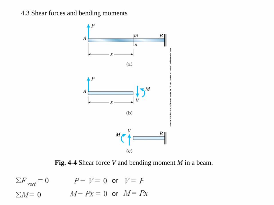
Sign convention are called deformation sign convention because they are based
upon how the material is deformed.
By contrast, when writing equations of equilibrium we use static sign convention, in
which forces are positive or negative according to their directions along the
coordinate axes.
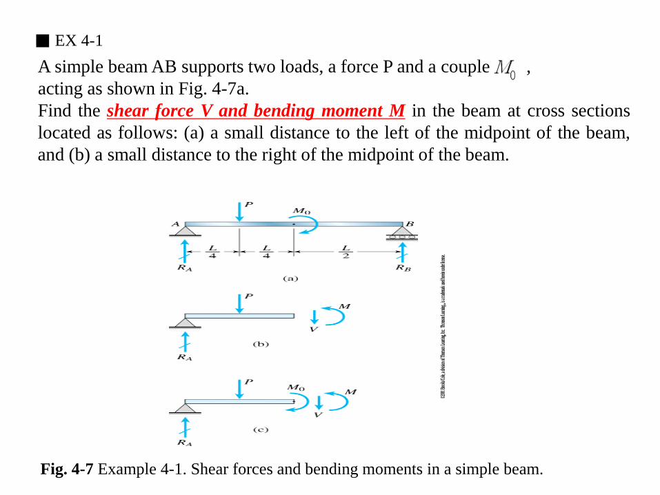
■ EX 4-1 A simple beam AB supports two loads, a force P and a couple , acting as shown in Fig. 4-7a. Find the shear force V and bending moment M in the beam at cross sections located as follows: (a) a small distance to the left of the midpoint of the beam, and (b) a small distance to the right of the midpoint of the beam.
Fig. 4-7 Example 4-1. Shear forces and bending moments in a simple beam.
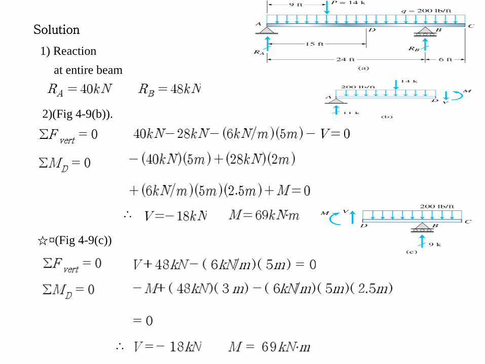
Solution
Reaction.
1) total free-body diagram
2) left-hand half of beam as the free body (Figure 4-7(b)).
(a)
(b) ∴
(c)
3) (Figure 4-7(c)).
(d,e)
■ Example 4-2
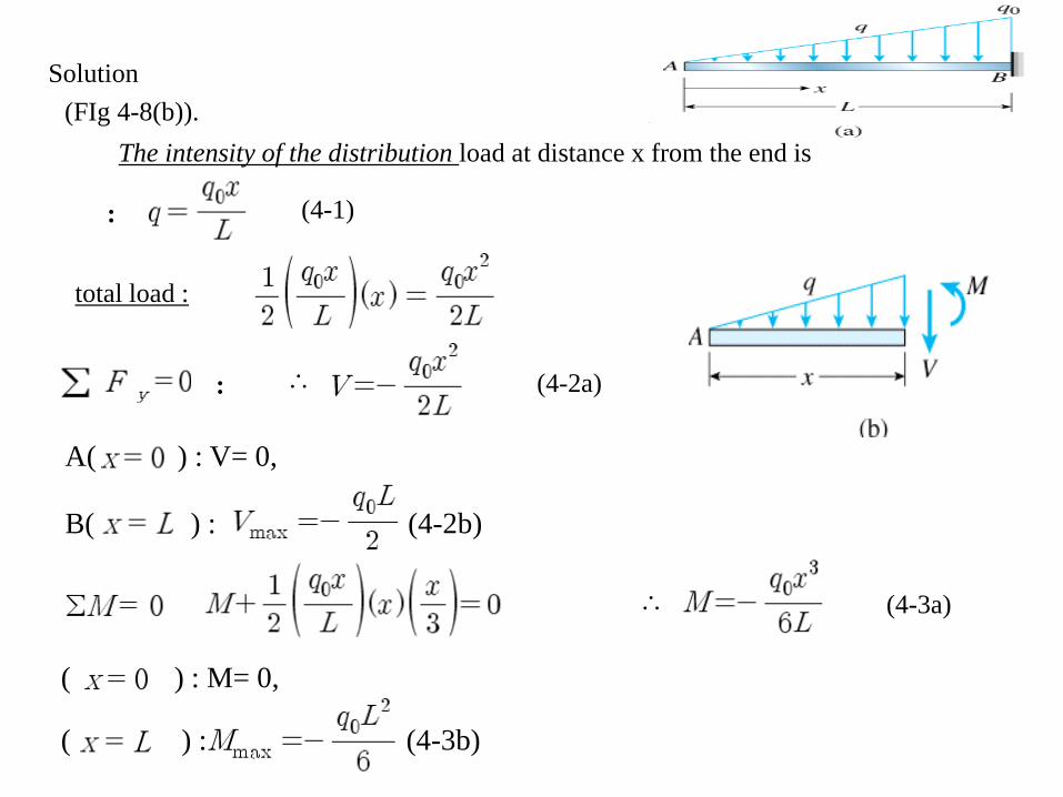
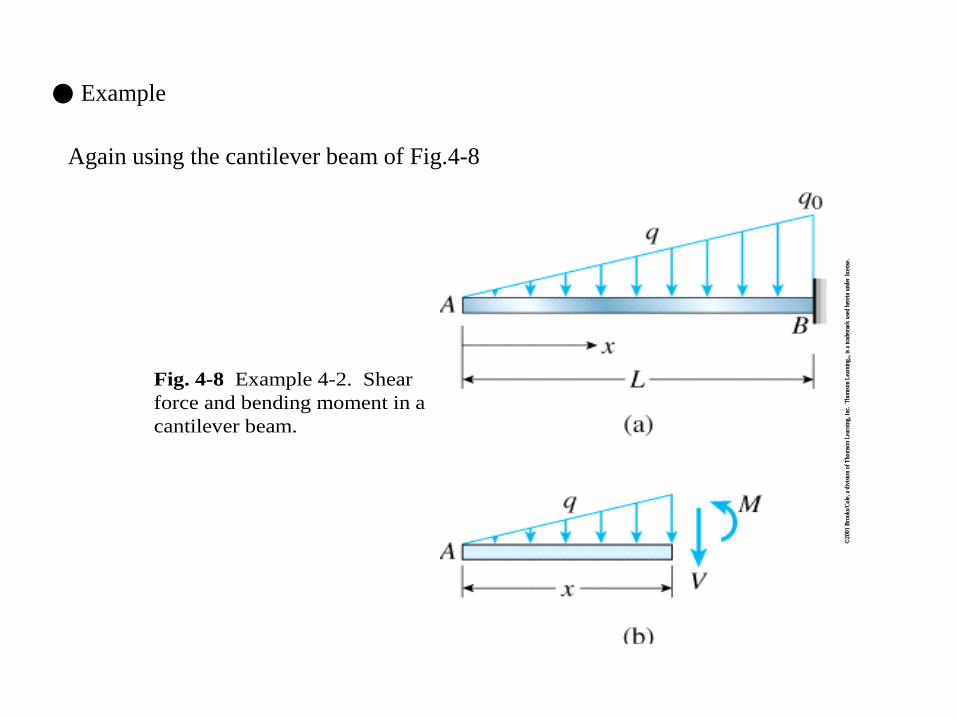
A cantilever beam that is free at end A and fixed at end B is subjected to a distributed load of linearly varying intensity q (Fig. 4-8a). The maximum intensity of the load occurs at the fixed support and is equal to . q0
Find the shear force V and bending moment M at distance x from the free end of the beam.
Fig. 4-8 Example 4-2. Shear force and bending moment in a cantilever beam.
Solution (FIg 4-8(b)).
The intensity of the distribution load at distance x from the end is
total load :
∴ (4-2a) :
(4-1) :
A( ) : V= 0,
B( ) : (4-2b)
∴ (4-3a)
( ) : M= 0,
( ) : (4-3b)
a
■ EX 4-3
A simple beam with an overhang is supported at points A and B(Fig. 4-9a). A uniform load of intensity acts throughout the length of the beam and a concentrated load acts at a point 9ft from the left-hand support. The span length is 24ft and the length of the overhang is 6ft. Calculate the shear force V and bending moment M at cross section D located 15ft from the left-hand support.
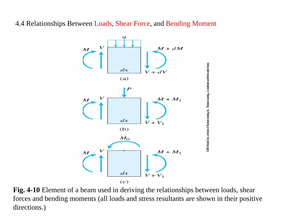
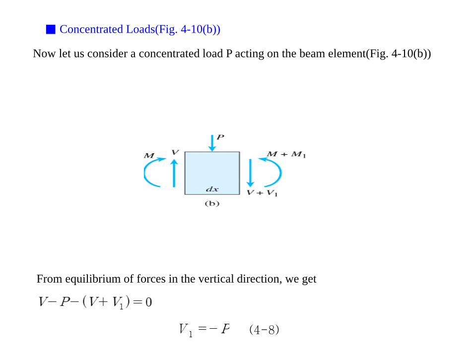
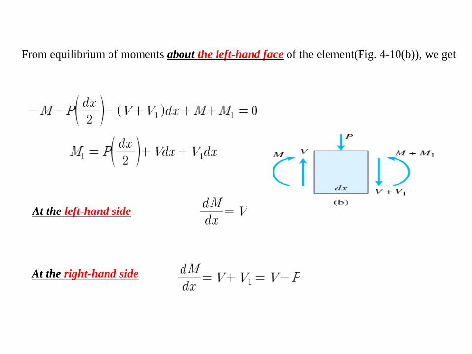
Fig. 4-10 Element of a beam used in deriving the relationships between loads, shear forces and bending moments (all loads and stress resultants are shown in their positive directions.)
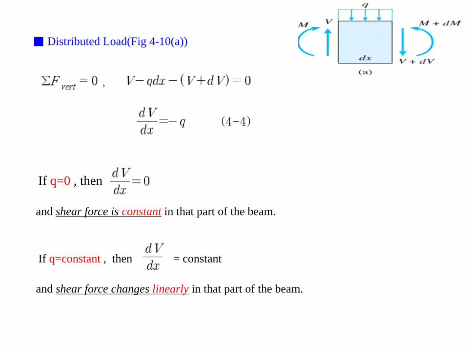
■ Distributed Load(Fig 4-10(a))
(4-4)
,
If q=0 , then
and shear force is constant in that part of the beam.
If q=constant , then = constant
and shear force changes linearly in that part of the beam.
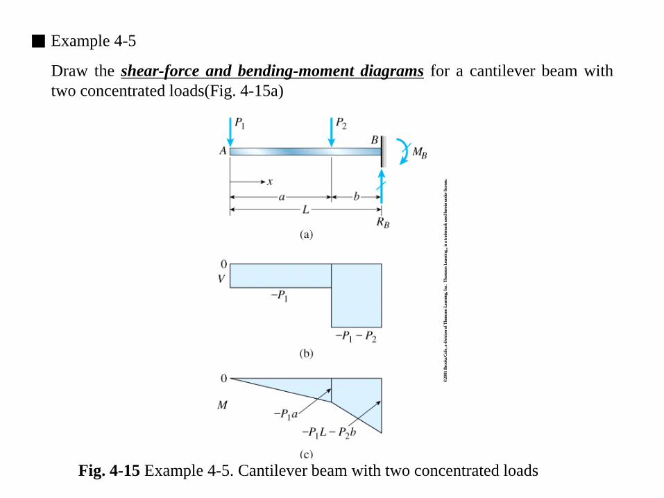
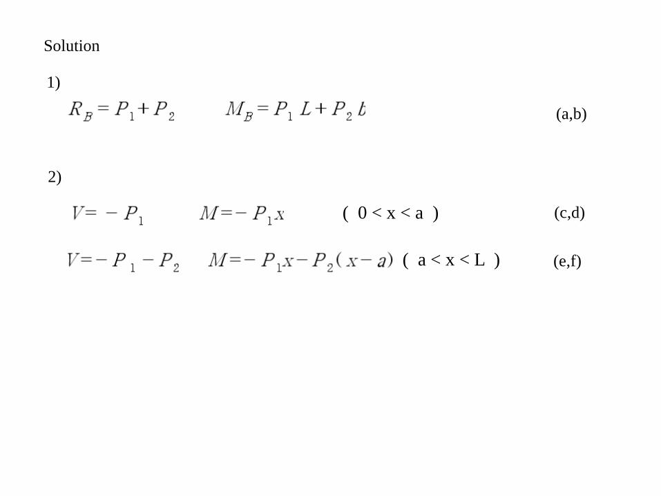
Fig. 4-15 Example 4-5. Cantilever beam with two concentrated loads
Solution
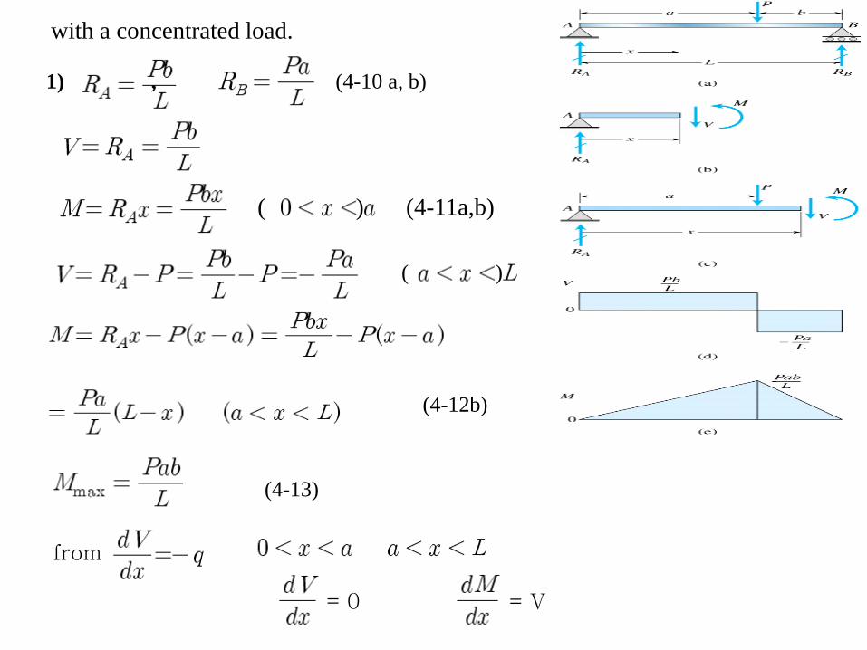
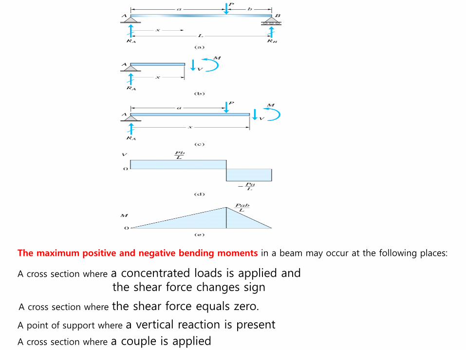
1)
(a,b)
2)
( 0 < x < a ) (c,d)
( a < x < L ) (e,f)
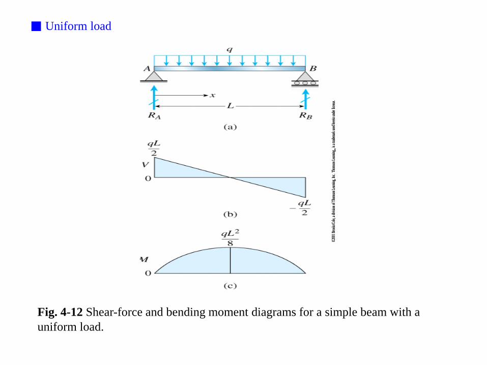
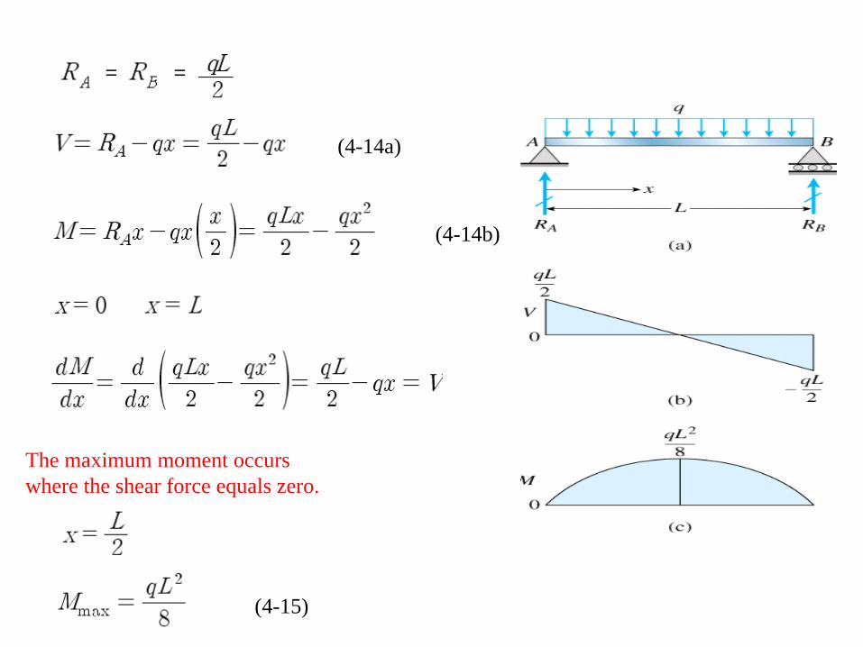
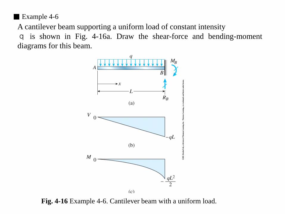
■ Example 4-6 A cantilever beam supporting a uniform load of constant intensity q is shown in Fig. 4-16a. Draw the shear-force and bending-moment diagrams for this beam.
Fig. 4-16 Example 4-6. Cantilever beam with a uniform load.
Solution
1)
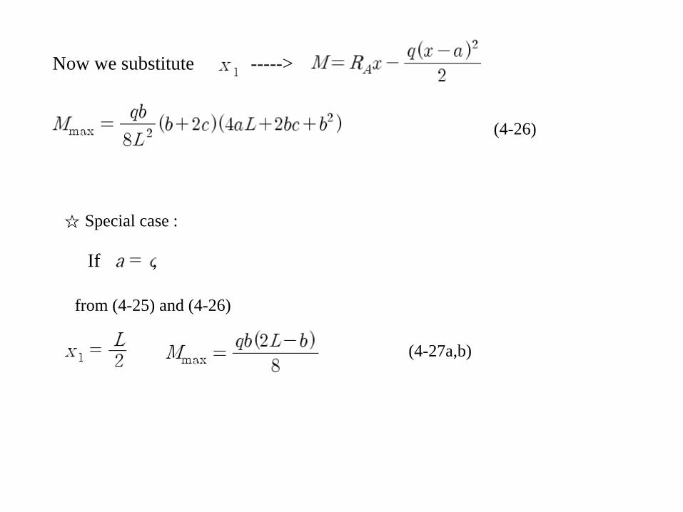
(4-28a,b)
2)
(4-29a,b)
3) (4-30a,b)
☆¤
(g)
(h)
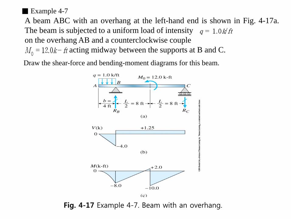
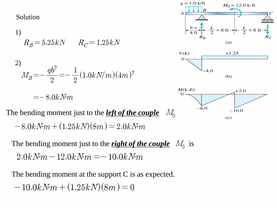
■ Example 4-7 A beam ABC with an overhang at the left-hand end is shown in Fig. 4-17a. The beam is subjected to a uniform load of intensity on the overhang AB and a counterclockwise couple acting midway between the supports at B and C. Draw the shear-force and bending-moment diagrams for this beam.


![[9] shear force n bending moment](https://static.documents.pub/doc/80x56/553af101550346f92f8b4613/9-shear-force-n-bending-moment.jpg)


