13
Manoj Chopade Roll No : 21 ME –Design (II Semester) Shear locking Phenomenon 27 th May 2014
| Date post: | 28-Dec-2015 |
| Category: |
Documents |
| Upload: | lonkardineshgmailcom |
| View: | 71 times |
| Download: | 16 times |

Manoj ChopadeRoll No : 21ME –Design (II Semester)
Shear locking Phenomenon
27th May 2014
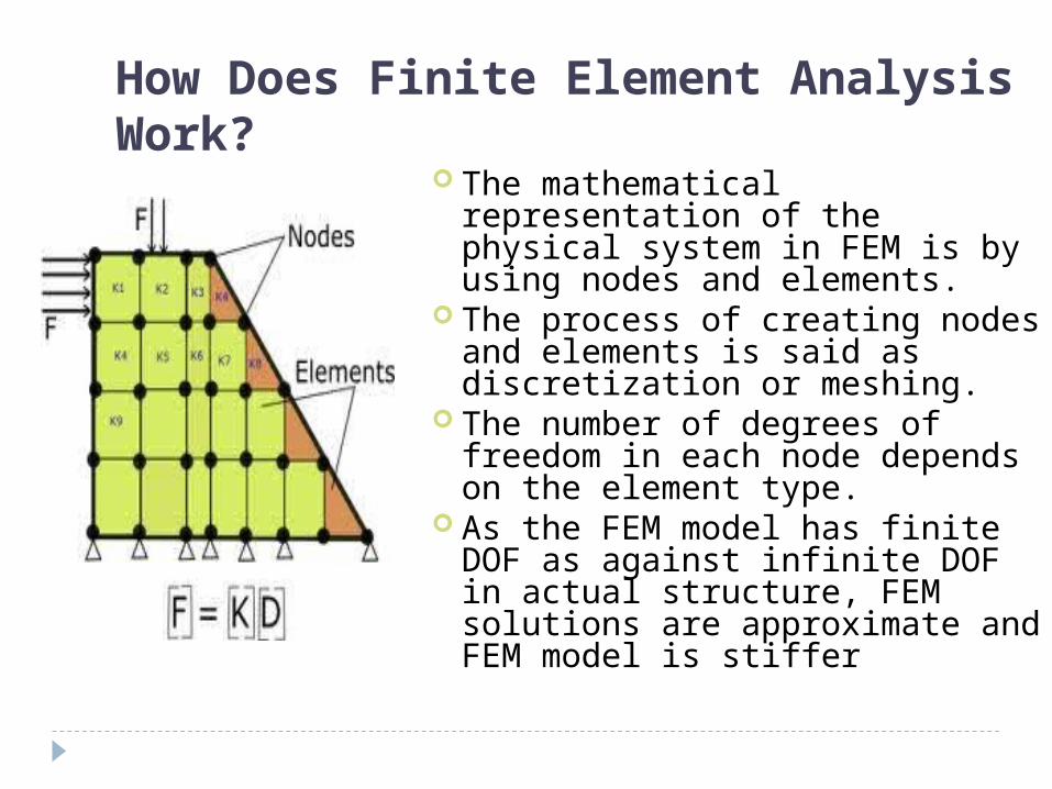
How Does Finite Element Analysis Work?
The mathematical representation of the physical system in FEM is by using nodes and elements.
The process of creating nodes and elements is said as discretization or meshing.
The number of degrees of freedom in each node depends on the element type.
As the FEM model has finite DOF as against infinite DOF in actual structure, FEM solutions are approximate and FEM model is stiffer
Shear locking Phenomenon
Error called “locking” and how it is being overcome by the commercial FEA codes.
In spite of providing approximate solutions to problems which cannot be solved analytically, there are some situations for which convergence is poor in FEM.
LOCKING :
Shear locking: Timoshenko beam theory works for all l/d ratio
whereas Bernoullie beam theory works for only large values of l/d ratio.
In thick beams , shear deformation becomes predominant and Bernoulli’s theory wont give accurate result.
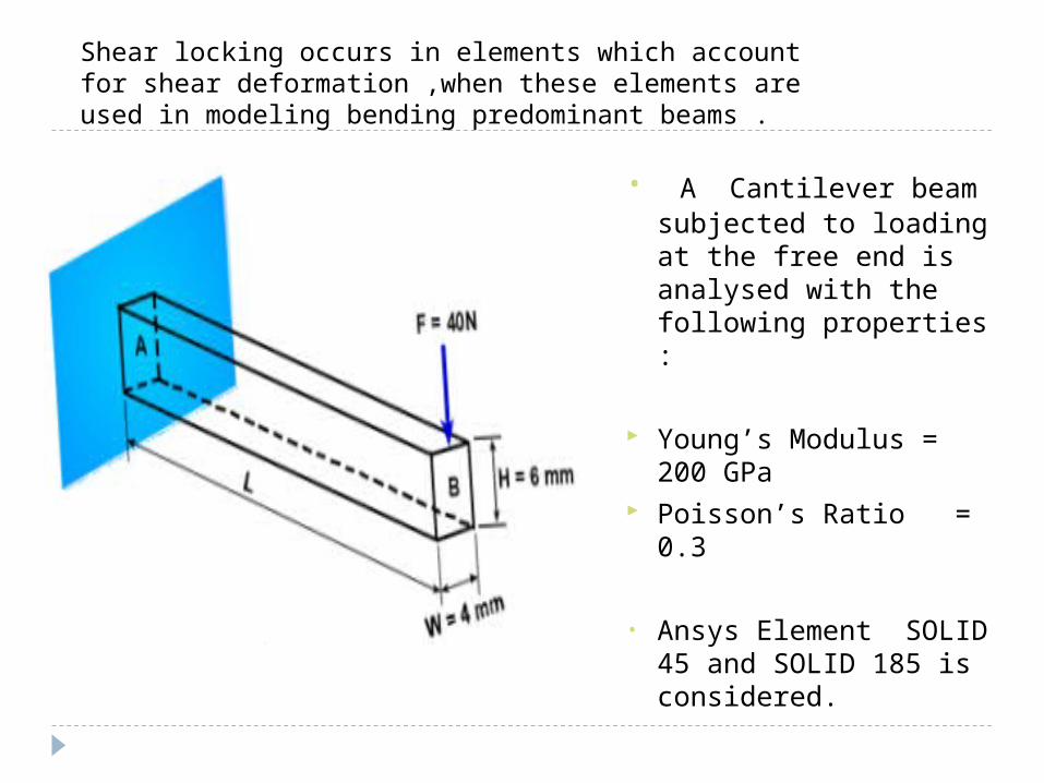
Shear locking occurs in elements which account for shear deformation ,when these elements are used in modeling bending predominant beams .
Shear locking occurs in elements which account for shear deformation ,when these elements are used in modeling bending predominant beams .
• A Cantilever beam subjected to loading at the free end is analysed with the following properties :
Young’s Modulus = 200 GPa
Poisson’s Ratio = 0.3
• Ansys Element SOLID 45 and SOLID 185 is considered.
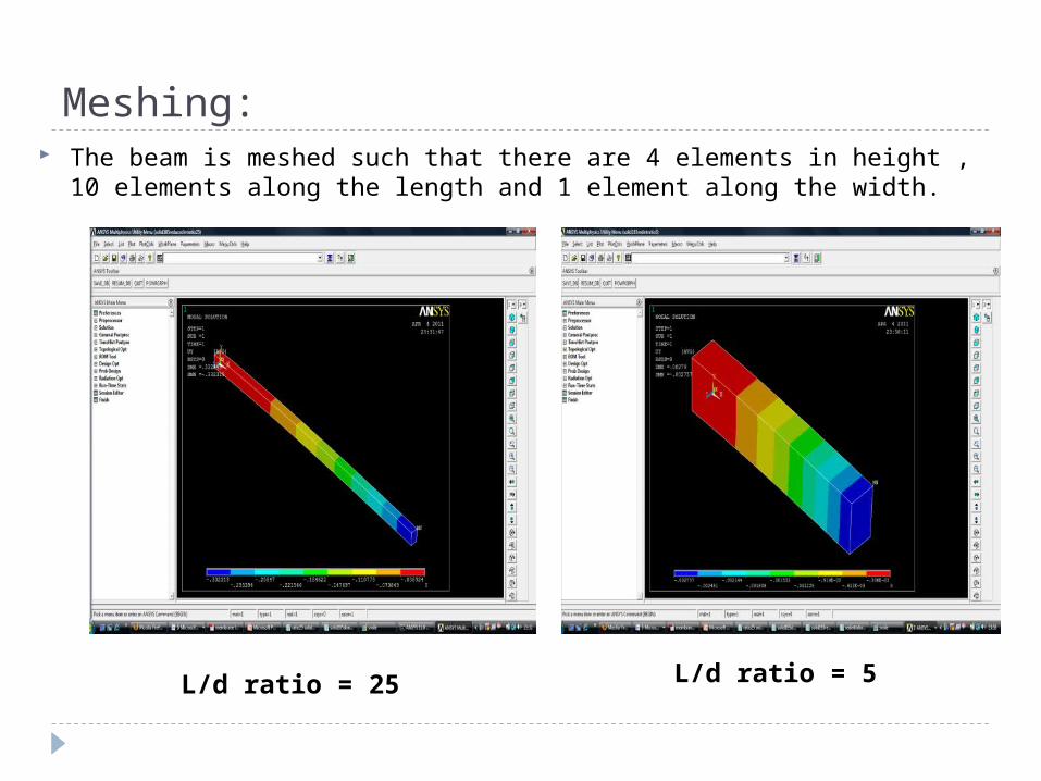
Meshing:
L/d ratio = 25 L/d ratio = 5
The beam is meshed such that there are 4 elements in height , 10 elements along the length and 1 element along the width.
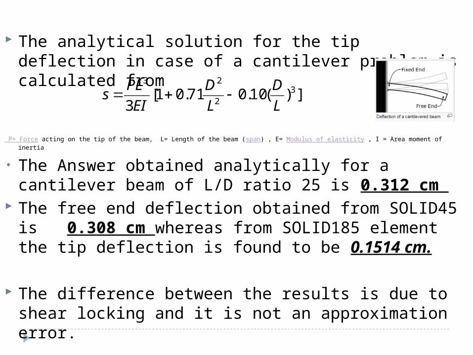
The analytical solution for the tip deflection in case of a cantilever problem is calculated from
P= Force acting on the tip of the beam, L= Length of the beam (span) , E= Modulus of elasticity , I = Area moment of inertia
• The Answer obtained analytically for a cantilever beam of L/D ratio 25 is 0.312 cm
The free end deflection obtained from SOLID45 is 0.308 cm whereas from SOLID185 element the tip deflection is found to be 0.1514 cm.
The difference between the results is due to shear locking and it is not an approximation error.
])(10.071.01[3
32
23
L
D
L
D
EI
PLs
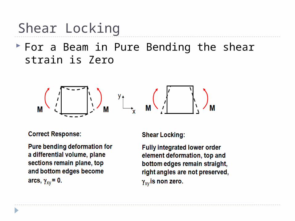
Shear Locking For a Beam in Pure Bending the shear strain is
Zero
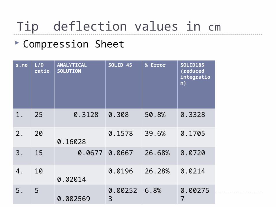
Tip deflection values in cm
s.no L/D ratio
ANALYTICAL SOLUTION
SOLID 45 % Error SOLID185 (reduced integration)
1. 25 0.3128 0.308 50.8% 0.3328
2. 20 0.16028 0.1578 39.6% 0.1705
3. 15 0.0677 0.0667 26.68% 0.0720
4. 10 0.02014 0.0196 26.28% 0.0214
5. 5 0.002569 0.002523
6.8% 0.002757
Compression Sheet
Interpretation of the results :
It is clear from the table, as the beam thickness increases (as shear becomes predominant) the error is minimized.
The error in the tip deflection values of
bending predominant beams is due to Shear locking.

THANK YOU
References : Finite Element Analysis by C.S.Krishnamoorthy , IIT ,
Madras. Strength of Materials- Elementary theory and
problems by Stephen Timoshenko Eric Quili Sun, “ Shear locking and hourglassing in
MSC Nastran, Abaqus and Ansys” www.cmmacs.ernet.in/cmmacs/pdf/ www.imechanica.org www.mscsoftware.com/events/vpd2006/na/
presentations/.../27.pdf www.eng-tips.org www.springerlink.com www.openpdf.com www.sciencedirect.com


![On the Assumed Natural Strain method to alleviate locking in … · 2014. 5. 27. · To alleviate shear locking in Reissner-Mindlin plate elements, Thai et al. [52] have implemented](https://static.documents.pub/doc/80x56/60b729ad20a87a2cf45b0e2a/on-the-assumed-natural-strain-method-to-alleviate-locking-in-2014-5-27-to-alleviate.jpg)


