In this study, a series of small and large scale direct shear tests were conducted to evaluate the effect of mixing fly ash in two ratios i.e. 20 and 25% by volume on the shear strength behaviour of coal mine overburden dump material and these results are compared with direct shear tests conducted on overburden dump material without fly ash. The effect of mixing fly ash on stability of both internal and external overburden dumps were assessed with FDM based slope stability software using determined shear strength parameters and dump slope angle were optimized for safe disposal of the fly ash by mixing it with overburden dumps in the coal mines. The investigation carried out as above revealed that fly ash mixed internal and external overburden dumps having an overall slope angle ranging between 24 to 280 in two benches of 30 m height is stable and disposal of fly ash can be carried out safely by mixing it with the coal mine overburden rock material. Keywords: overburden dumps, fly ash, direct shear test, external dumps, internal dumps, stability.
INTRODUCTION
Indian Thermal Power Plants (TPP) are facing problems of disposal of fly ash. Continuous research either for its effective utilization in various industries or safe disposal in mine voids and low lying areas are being carried out in India. In spite of lot of efforts and stringent regulation by the Ministry of Environment and Forest (MoEF), Govt. of India, the utilization of fly ash in India has achieved merely 60 %, most of which is being utilized for making cement, bricks and concrete and remaining being disposed off in ash ponds. A very little percentage (6 to 10 %) of fly ash generated are being disposed off in mines and reclamation of low lying areas in India (Central Electricity Authority, 2014). There is a continuous need to explore and promote all possible modes of fly ash utilization or its safe disposal. More than 80, 000 MW of new power generation capacity is expected to come up in the country in the next five years. Out of this major portion of around 60 to 70 per cent would come from coal based TPP. Location of TPP near open cast coal mines in India and huge availability of fly ash and overburden dump rock material there on can create very favourable conditions for disposing these waste materials in mine voids. Recent notification issued by MoEF has made mandatory to utilize fly ash for reclamation and compaction of low lying areas and construction of roads and embankments for all the construction activities carried out within radius of 100 km from TPP. A similar compulsion has been made for stowing of underground mine voids with fly ash and mixing of 25 % fly ash by volume in the overburden dumps formed in all the opencast mines situated within a radius of 50 km from TPP.
Fly ash is non-plastic, fine powdery material generally having negligible cohesion in dry condition and internal friction angle in the range of 290 to 370, (Pandian 2004), while under wet condition it hardens and strengthen with age due to its self-cementing properties and exhibits some cohesion (Porbaha et al. 2000). Fly ash consists of often hollow spheres of silicon, aluminum, and iron oxides and unoxidized carbon and is pozzolanic in nature and contains some lime. A lot of research has been carried out on stabilization of expansive soil with fly ash and it has been revealed that mixing of fly ash improves the performance of soil by improving its Atterberg limits, compressive strength, durability, hydration, permeability and compaction characteristics (Cokca, 2001; Prabhakar et al. 2004; Sharma et al., 2006; Geliga et al. 2010; Brooks et al. 2011; Bose 2012; Takhelmayum et al., 2013). Addition of fly ash in the soil also resulted in increased shear strength of the mixture (Phani Kumar and Sharma, 2004). A plenty of research regarding effect of mixing fly ash with mine overburden rock on its CBR were conducted to investigate the suitability of fly ash as a road construction material (Pandian, 2004; Kim et al. 2005; Arora and Aydilek, 2006; Edil and Benson, 2007; Okunade, 2010; Kumar, 2010; Santos et al. 2011). Utilization of fly ash for construction of highway embankments has also been investigated by some researchers (Martin et al 1990; Yoon et al. 2009).
There are two main safety and environmental concerns in the disposal of fly ash when it is mixed with the overburden dumps, the first one is related with changes in shear strength behaviour of the overburden dumps and its stability and second one related with the ground water contamination from fly ash leachates. Some research has
been carried out on the environmental characteristics of Indian fly ash leachates and it has been reported that the fly ash interaction with the ground/mine water produces toxic elements well below the permissible/threshold levels (Singh, 2005; Maiti et. al. 2005; Sarode et al. 2010; Kumar Ritesh, 2010; Behra and Mishra, 2012). Ground water contamination due to leaching of heavy and toxic metals from fly ash can also be minimized and controlled if they are separated from the ground water aquifer by suitable liners (Snigdha and Batra, 2006). Very few research work were found available which has examined the change in shear strength behaviour of mixing fly ash with coal mine overburden dump materials and the stability of fly ash mixed overburden dumps. Singh, 2011, studied the effect of mixing 30% fly ash on factor of safety for an overburden dump slope of a height of 120 m under both under dry and wet conditions using numerical simulation. He found that the slope remained stable under dry condition while under wet condition reduction in factor of safety of the slope was reported. Jayanthu et al, 2012, studied the dump stability of fly ash (25 % by weight) mixed overburden dumps of an opencast coal mine having a total height of 120 m. Two types of dumps were formed, one with alternate layer of fly ash and overburden and the other by mixing fly ash in the overburden dumps. In both conditions, dumps were found stable. Pradhan et al. 2014 also analyzed the stability of dump slope of 60 m height having an overall slope angle of 320 made up of overburden materials randomly mixed with 20% fly ash and found the slope stable. In all the above studies, shear strength parameters for slope stability analysis were determined by conducting small scale triaxial tests on fly ash mixed with sand and silty fractions of dump material. The main drawback of the studies was the inclusion of only fine portion of the dump material for shear strength determination of the mixture formed with fly ash. A shortcoming to this small scale laboratory testing is that oversized rock fragments are usually scalped to accommodate the testing equipment capacity. The influence of coarser fraction of rock fragments present on the overburden dumps on its shear strength is not taken in to consideration. These shortcomings lead to uncertainties associated with the assignment of accurate shear strength parameters for slope stability modelling and design. Determination of accurate shear strength characteristics of fly ash mixed mine overburden rock is one of the most important parameter in design and analysis of stability of fly ash mixed overburden dump slopes.
This study primarily aims to characterize the shear strength behaviour of fly ash mixed overburden dump material of coal mines by conducting a series of small and large scale direct shear tests which will take care of both fine and coarse sized rock fragments present in the dump materials. An assessment of stability of external and internal overburden dumps dumps were carried out using
Flac/Slope 2D version 6.0 and dump slope angles were optimized for dump height of 60 m. MATERIALS AND METHODS
Bulk quantities of overburden dump samples were collected from a large, partially consolidated rock dump from a large open-cast coal mine situated in Korba area of SECL, Bilaspur, Chattishgarh. During collection of samples from the dump, rock fragments larger in sizes more than 80 mm were discarded at the site itself. Particle size analysis of the dump materials were carried out in the laboratory as per IS Standard IS 2720 (Part 4) 1985 to know the size distribution of the rock fragments forming the dump and a modelled gradation curve (Proto Type Sample) was prepared to represent the size of rock fragments present in the dump material. The various relevant geotechnical index properties were measured in the laboratory to classify the investigated materials. Laboratory tests were carried out on the experimental overburden dump rock samples, which include specific gravity, point load strength index, slake durability tests, Atterberg limits etc. The specific gravity of the experimental samples containing overburden rock fragments were determined using volumetric flask method as per IS: 2720 (Part 3-1980). Point load strength index and Slake durability of the rock samples were determined as per IS: 8764 (1998) and IS:10050 (1981) test procedure. In order to reduce the field particle sizes to laboratory particle sizes to suit the available shear box size, the laboratory specimens were scaled by some degrees. During sieving of dump sample, the rock fragments passing through different sieve sizes ranging from 31.5 mm to less than 200 μm were collected in separate bags /containers. Using parallel gradation technique developed by John Lowe (Lowe, 1964), these rock fragments of different sizes were then mixed together to produce a well graded experimental sample having size distribution parallel to the proto type representing the particle size distribution of the actual dump material in the field. Numerous researchers have tested materials based on this model and validated the effectiveness of this model to estimate the shear strength of rock fills and rail ballast (Sitharam and Nimbkar, 2000; Varadrajan et al. 2003; Cambio and Ge, 2007; Sevi, 2008; Ghanbari, 2008). This sample preparation takes into account the effect of coarser rock fragments on the compaction behavior and shear strength behaviour of the dump material. In this research, test gradation was made following the above method having similar coefficient of uniformity and curvature using two maximum particle diameters of 31.5 mm, and 3.75 mm considering the size of the shear box (300 mm x300 mm x190 mm and 60 mm x60mmx31 mm).
The various important and relevant geotechnical parameters of studied materials are listed in Table-1 and the gradational characteristics is summarized in Table-2.
Table-1. Geotechnical properties of experimental material.
Properties Overburden rock
sample Fly ash
Specific gravity 2.65 2.1
Liquid limit 18.6% 35%
Plastic limit Non Plastic Non Plastic
Point load strength index, MPa
0.4 to 1 NA
Maximum unit weight, KN/m3
19.83 13.34
Optimum moisture content, %
9 25
Table-2. Gradational characteristics of experimental overburden dump sample.
Gradation characteristics Insitu dump
sample
Coarse fractions of overburden rock sample
Fine fractions of overburden rock sample
Maximum fragment size, Dmax, mm
80 31.5 4.75
Average fragment size, D50, mm 18.5 9 1.6
Coefficient of uniformity, Cu 23 24 23
Coefficient of curvature, Cc 2.80 2.78 2.78
% fines less than 4.75 mm by weight, f200
22 33 100
% fines less than 0.6 mm by weight
7 11 25
Group symbol as per BIS GW GW-GM SM
Sample name Proto Type
Sample (PTS)
Gravel type overburden
dump sample 1 (GTODS1)
Sand Type Overburden
Dump Sample (STODS)
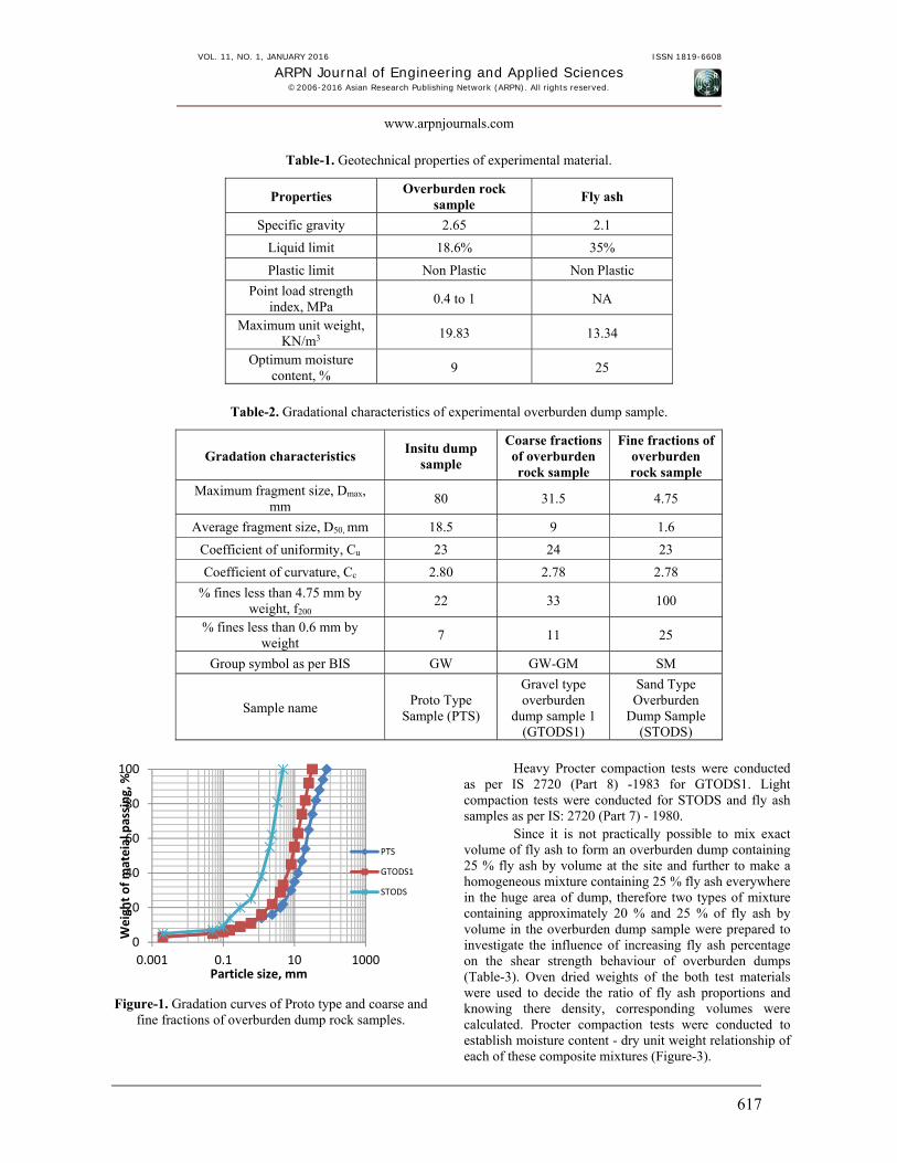
Figure-1. Gradation curves of Proto type and coarse and fine fractions of overburden dump rock samples.
Heavy Procter compaction tests were conducted as per IS 2720 (Part 8) -1983 for GTODS1. Light compaction tests were conducted for STODS and fly ash samples as per IS: 2720 (Part 7) - 1980.
Since it is not practically possible to mix exact volume of fly ash to form an overburden dump containing 25 % fly ash by volume at the site and further to make a homogeneous mixture containing 25 % fly ash everywhere in the huge area of dump, therefore two types of mixture containing approximately 20 % and 25 % of fly ash by volume in the overburden dump sample were prepared to investigate the influence of increasing fly ash percentage on the shear strength behaviour of overburden dumps (Table-3). Oven dried weights of the both test materials were used to decide the ratio of fly ash proportions and knowing there density, corresponding volumes were calculated. Procter compaction tests were conducted to establish moisture content - dry unit weight relationship of each of these composite mixtures (Figure-3).
Large scale direct shear tests for this study were carried out using multispeed direct shear equipment having a shear box of 300 mm by 300 mm by 190 mm deep. The prepared various experimental dump rock materials were pretreated by adding and mixing distilled water so that the optimum water content for the mixture were obtained, and the same were compacted in the shear box in five different layers. In each layer compaction was given using a 2.5 kg rammer so as to obtain 90% compaction relative to the maximum dry density. In the
direct shear test, the soil is first consolidated under an applied normal stress. After consolidation is completed, the specimen is sheared directly at a constant rate of deformation. The strain rates chosen were very low and of the order of 0.2 mm/min, so that excess pore pressure which might build up during the test could be dissipated easily. Small scale direct shear tests were carried in a similar manner using a shear box of 60 mm by 60 mm by 31 mm deep at the same strain rate.
Table-3. List of experimental samples prepared for various compaction and shear tests.
Name of the sample Composition Compaction tests
(Heavy /Light) Direct Shear Tests
(Large/Small)
GTODS1 Only OB Heavy Large
STODS Only OB Light Small
GTODS1M20F 80% OB + 20% FA Heavy Large
GTODS1M25F 75% OB + 25% FA Heavy Large
STODSM20F 80% OB + 8% FA Light Small
STODSM25F 75% OB + 25% FA Light Small
RESULTS AND DISCUSSIONS
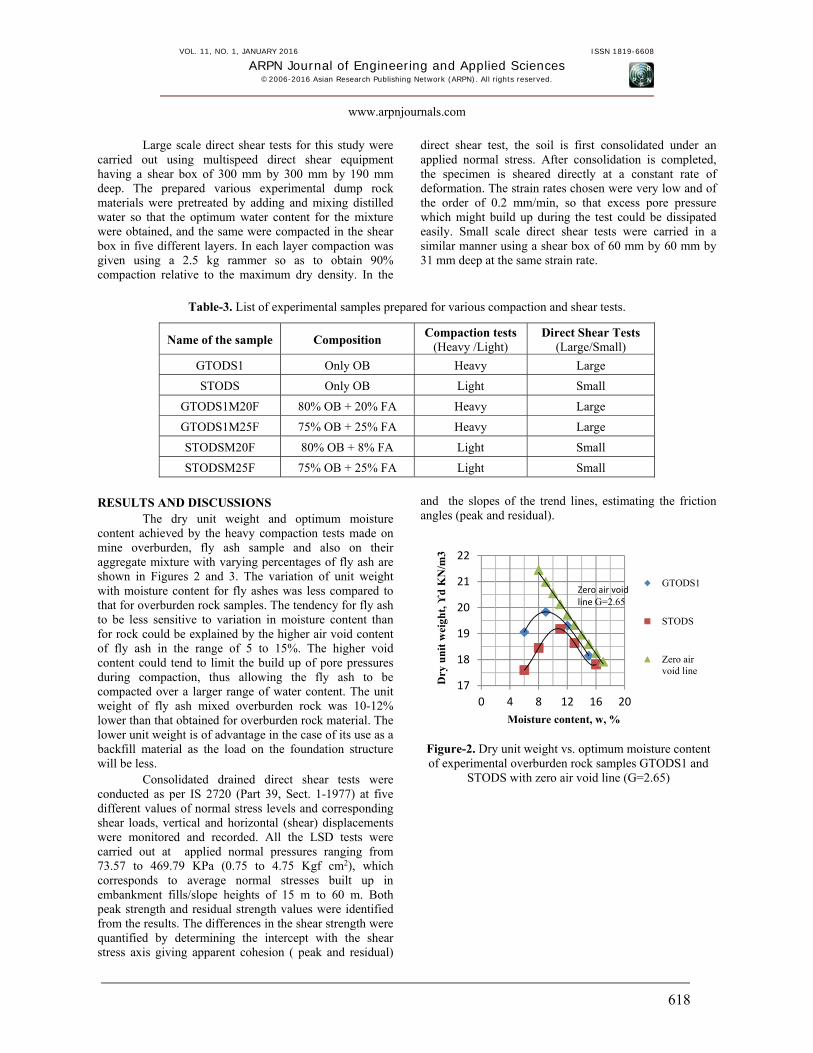
The dry unit weight and optimum moisture content achieved by the heavy compaction tests made on mine overburden, fly ash sample and also on their aggregate mixture with varying percentages of fly ash are shown in Figures 2 and 3. The variation of unit weight with moisture content for fly ashes was less compared to that for overburden rock samples. The tendency for fly ash to be less sensitive to variation in moisture content than for rock could be explained by the higher air void content of fly ash in the range of 5 to 15%. The higher void content could tend to limit the build up of pore pressures during compaction, thus allowing the fly ash to be compacted over a larger range of water content. The unit weight of fly ash mixed overburden rock was 10-12% lower than that obtained for overburden rock material. The lower unit weight is of advantage in the case of its use as a backfill material as the load on the foundation structure will be less.
Consolidated drained direct shear tests were conducted as per IS 2720 (Part 39, Sect. 1-1977) at five different values of normal stress levels and corresponding shear loads, vertical and horizontal (shear) displacements were monitored and recorded. All the LSD tests were carried out at applied normal pressures ranging from 73.57 to 469.79 KPa (0.75 to 4.75 Kgf cm2), which corresponds to average normal stresses built up in embankment fills/slope heights of 15 m to 60 m. Both peak strength and residual strength values were identified from the results. The differences in the shear strength were quantified by determining the intercept with the shear stress axis giving apparent cohesion ( peak and residual)
and the slopes of the trend lines, estimating the friction angles (peak and residual).
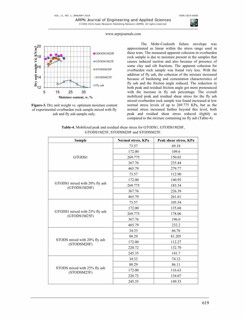
Figure-2. Dry unit weight vs. optimum moisture content of experimental overburden rock samples GTODS1 and
Figure-3. Dry unit weight vs. optimum moisture content of experimental overburden rock sample mixed with fly
ash and fly ash sample only.
The Mohr-Coulomb failure envelope was approximated as linear within the stress range used in these tests. The measured apparent cohesion in overburden rock sample is due to moisture present in the samples that causes induced suction and also because of presence of some clay and silt fractions. The apparent cohesion for overburden rock sample was found very less. With the addition of fly ash, the cohesion of the mixture increased because of hardening and cementation characteristics of fly ash and the friction angle reduced. The reduction in both peak and residual friction angle got more pronounced with the increase in fly ash percentage. The overall mobilized peak and residual shear stress for the fly ash mixed overburden rock sample was found increased at low normal stress levels of up to 269.775 KPa, but as the normal stress increased further beyond this level, both peak and residual shear stress reduced slightly as compared to the mixture containing no fly ash (Table-4).
Table-4. Mobilized peak and residual shear stress for GTODS1, GTODS1M20F, GTODS1M25F, STODSM20F and STODSM25F.
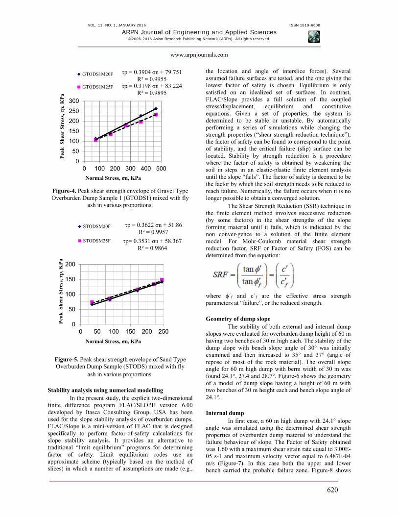
Figure-4. Peak shear strength envelope of Gravel Type Overburden Dump Sample 1 (GTODS1) mixed with fly
ash in various proportions.
Figure-5. Peak shear strength envelope of Sand Type Overburden Dump Sample (STODS) mixed with fly
ash in various proportions. Stability analysis using numerical modelling
In the present study, the explicit two-dimensional finite difference program FLAC/SLOPE version 6.00 developed by Itasca Consulting Group, USA has been used for the slope stability analysis of overburden dumps. FLAC/Slope is a mini-version of FLAC that is designed specifically to perform factor-of-safety calculations for slope stability analysis. It provides an alternative to traditional “limit equilibrium” programs for determining factor of safety. Limit equilibrium codes use an approximate scheme (typically based on the method of slices) in which a number of assumptions are made (e.g.,
the location and angle of interslice forces). Several assumed failure surfaces are tested, and the one giving the lowest factor of safety is chosen. Equilibrium is only satisfied on an idealized set of surfaces. In contrast, FLAC/Slope provides a full solution of the coupled stress/displacement, equilibrium and constitutive equations. Given a set of properties, the system is determined to be stable or unstable. By automatically performing a series of simulations while changing the strength properties (“shear strength reduction technique”), the factor of safety can be found to correspond to the point of stability, and the critical failure (slip) surface can be located. Stability by strength reduction is a procedure where the factor of safety is obtained by weakening the soil in steps in an elastic-plastic finite element analysis until the slope “fails”. The factor of safety is deemed to be the factor by which the soil strength needs to be reduced to reach failure. Numerically, the failure occurs when it is no longer possible to obtain a converged solution.
The Shear Strength Reduction (SSR) technique in the finite element method involves successive reduction (by some factors) in the shear strengths of the slope forming material until it fails, which is indicated by the non conver-gence to a solution of the finite element model. For Mohr-Coulomb material shear strength reduction factor, SRF or Factor of Safety (FOS) can be determined from the equation:
where ϕ΄f and c΄f are the effective stress strength parameters at “failure”, or the reduced strength. Geometry of dump slope
The stability of both external and internal dump slopes were evaluated for overburden dump height of 60 m having two benches of 30 m high each. The stability of the dump slope with bench slope angle of 30° was initially examined and then increased to 35° and 37° (angle of repose of most of the rock material). The overall slope angle for 60 m high dump with berm width of 30 m was found 24.1°, 27.4 and 28.7°. Figure-6 shows the geometry of a model of dump slope having a height of 60 m with two benches of 30 m height each and bench slope angle of 24.1°. Internal dump
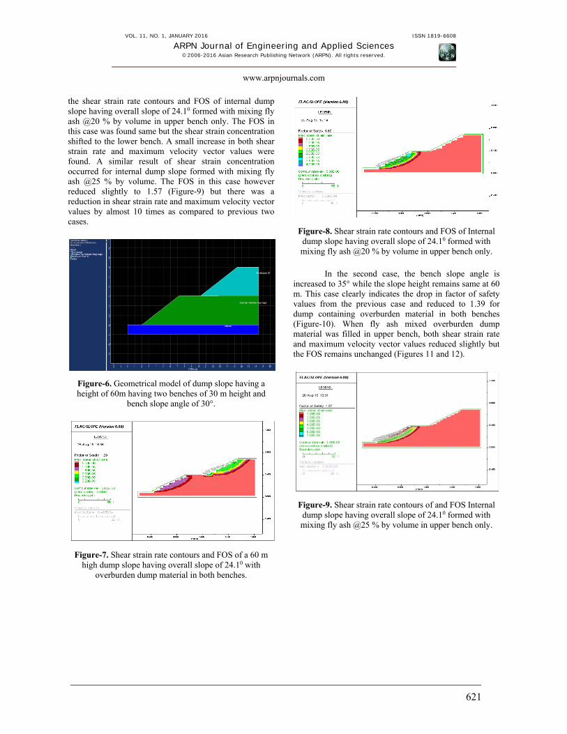
In first case, a 60 m high dump with 24.1° slope angle was simulated using the determined shear strength properties of overburden dump material to understand the failure behaviour of slope. The Factor of Safety obtained was 1.60 with a maximum shear strain rate equal to 3.00E-05 s-1 and maximum velocity vector equal to 6.487E-04 m/s (Figure-7). In this case both the upper and lower bench carried the probable failure zone. Figure-8 shows
the shear strain rate contours and FOS of internal dump slope having overall slope of 24.10 formed with mixing fly ash @20 % by volume in upper bench only. The FOS in this case was found same but the shear strain concentration shifted to the lower bench. A small increase in both shear strain rate and maximum velocity vector values were found. A similar result of shear strain concentration occurred for internal dump slope formed with mixing fly ash @25 % by volume. The FOS in this case however reduced slightly to 1.57 (Figure-9) but there was a reduction in shear strain rate and maximum velocity vector values by almost 10 times as compared to previous two cases.
Figure-6. Geometrical model of dump slope having a height of 60m having two benches of 30 m height and
bench slope angle of 30°.
Figure-7. Shear strain rate contours and FOS of a 60 m high dump slope having overall slope of 24.10 with
overburden dump material in both benches.
Figure-8. Shear strain rate contours and FOS of Internal dump slope having overall slope of 24.10 formed with mixing fly ash @20 % by volume in upper bench only.
In the second case, the bench slope angle is
increased to 35° while the slope height remains same at 60 m. This case clearly indicates the drop in factor of safety values from the previous case and reduced to 1.39 for dump containing overburden material in both benches (Figure-10). When fly ash mixed overburden dump material was filled in upper bench, both shear strain rate and maximum velocity vector values reduced slightly but the FOS remains unchanged (Figures 11 and 12).
Figure-9. Shear strain rate contours of and FOS Internal dump slope having overall slope of 24.10 formed with mixing fly ash @25 % by volume in upper bench only.
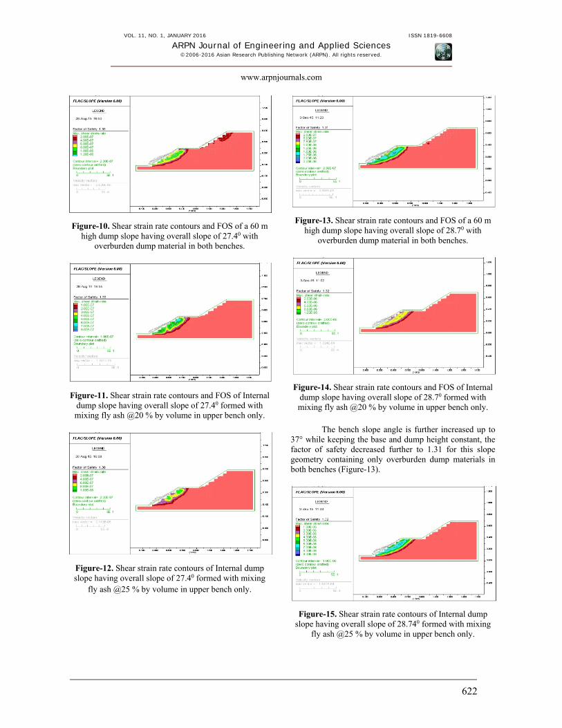
Figure-10. Shear strain rate contours and FOS of a 60 m high dump slope having overall slope of 27.40 with
overburden dump material in both benches.
Figure-11. Shear strain rate contours and FOS of Internal dump slope having overall slope of 27.40 formed with mixing fly ash @20 % by volume in upper bench only.
Figure-12. Shear strain rate contours of Internal dump slope having overall slope of 27.40 formed with mixing
fly ash @25 % by volume in upper bench only.
Figure-13. Shear strain rate contours and FOS of a 60 m high dump slope having overall slope of 28.70 with
overburden dump material in both benches.
Figure-14. Shear strain rate contours and FOS of Internal dump slope having overall slope of 28.70 formed with mixing fly ash @20 % by volume in upper bench only.
The bench slope angle is further increased up to
37° while keeping the base and dump height constant, the factor of safety decreased further to 1.31 for this slope geometry containing only overburden dump materials in both benches (Figure-13).
Figure-15. Shear strain rate contours of Internal dump slope having overall slope of 28.740 formed with mixing
The maximum shear strain accumulated in lower bench only. In case of fly ash mixed overburden dumps, the FOS value remains almost unchanged but both the shear strain rate and maximum velocity vector was found increased (Figures 14 and 15). The bench slope angle was not increased further and the simulation was stopped here as the FOS value approximately reaches to 1.30. This value of FOS can be used for safe and stable design of internal dumps mixed with fly ash in its upper bench only. The analysis revealed that there is very marginal effect on stability of overburden slopes when the fly ash is mixed within 20 to 25 % by volume in the upper bench of internal overburden dumps of 60 m height. The disposal of fly ash in the upper benches of internal overburden dumps of 60 m high can be carried out without reducing the existing dump slope angle. The numerical analysis also revealed overall deformation of the slope material in case fly ash mixed overburden dump slopes was found slightly lesser. External dumps
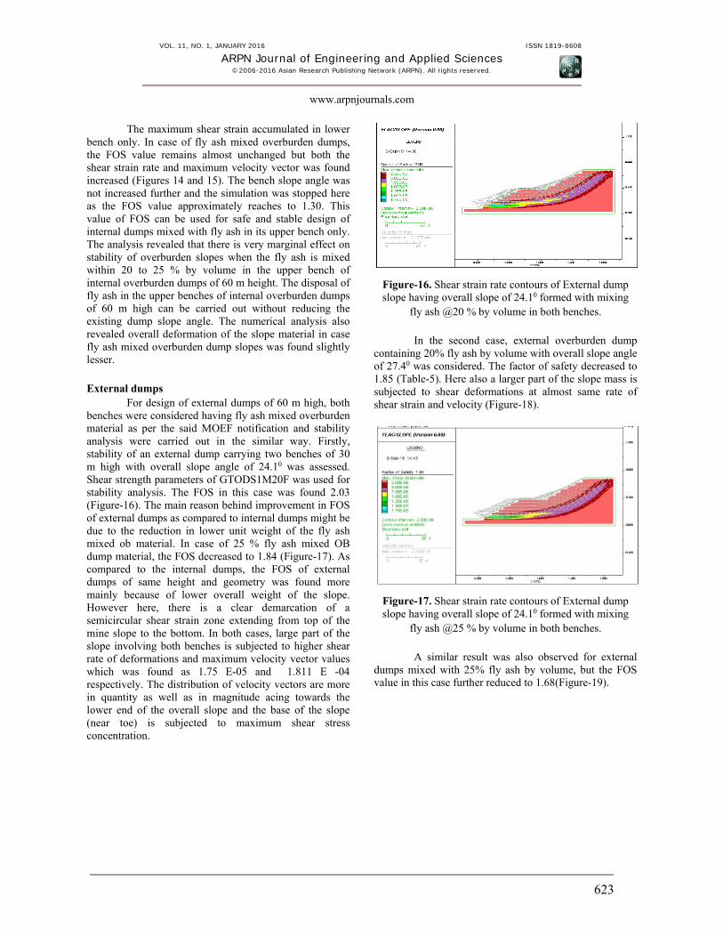
For design of external dumps of 60 m high, both benches were considered having fly ash mixed overburden material as per the said MOEF notification and stability analysis were carried out in the similar way. Firstly, stability of an external dump carrying two benches of 30 m high with overall slope angle of 24.10 was assessed. Shear strength parameters of GTODS1M20F was used for stability analysis. The FOS in this case was found 2.03 (Figure-16). The main reason behind improvement in FOS of external dumps as compared to internal dumps might be due to the reduction in lower unit weight of the fly ash mixed ob material. In case of 25 % fly ash mixed OB dump material, the FOS decreased to 1.84 (Figure-17). As compared to the internal dumps, the FOS of external dumps of same height and geometry was found more mainly because of lower overall weight of the slope. However here, there is a clear demarcation of a semicircular shear strain zone extending from top of the mine slope to the bottom. In both cases, large part of the slope involving both benches is subjected to higher shear rate of deformations and maximum velocity vector values which was found as 1.75 E-05 and 1.811 E -04 respectively. The distribution of velocity vectors are more in quantity as well as in magnitude acing towards the lower end of the overall slope and the base of the slope (near toe) is subjected to maximum shear stress concentration.
Figure-16. Shear strain rate contours of External dump slope having overall slope of 24.10 formed with mixing
fly ash @20 % by volume in both benches.
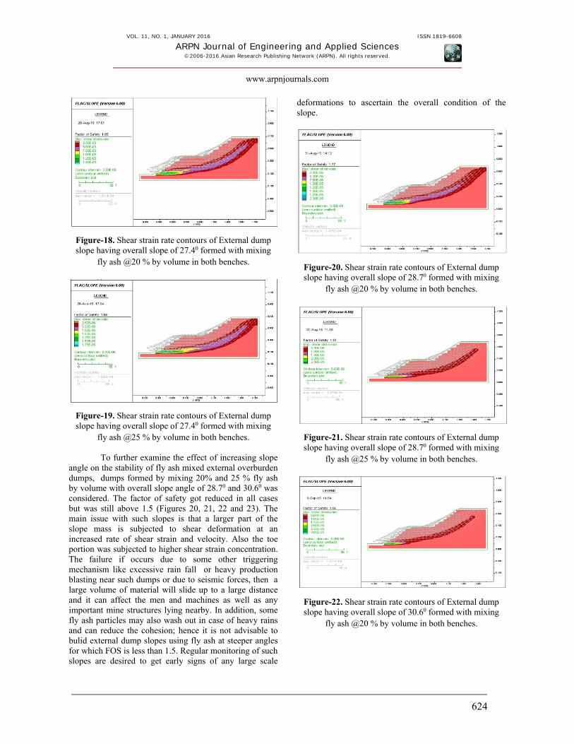
In the second case, external overburden dump containing 20% fly ash by volume with overall slope angle of 27.40 was considered. The factor of safety decreased to 1.85 (Table-5). Here also a larger part of the slope mass is subjected to shear deformations at almost same rate of shear strain and velocity (Figure-18).
Figure-17. Shear strain rate contours of External dump slope having overall slope of 24.10 formed with mixing
fly ash @25 % by volume in both benches.
A similar result was also observed for external dumps mixed with 25% fly ash by volume, but the FOS value in this case further reduced to 1.68(Figure-19).
Figure-18. Shear strain rate contours of External dump slope having overall slope of 27.40 formed with mixing
fly ash @20 % by volume in both benches.
Figure-19. Shear strain rate contours of External dump slope having overall slope of 27.40 formed with mixing
fly ash @25 % by volume in both benches.
To further examine the effect of increasing slope angle on the stability of fly ash mixed external overburden dumps, dumps formed by mixing 20% and 25 % fly ash by volume with overall slope angle of 28.70 and 30.60 was considered. The factor of safety got reduced in all cases but was still above 1.5 (Figures 20, 21, 22 and 23). The main issue with such slopes is that a larger part of the slope mass is subjected to shear deformation at an increased rate of shear strain and velocity. Also the toe portion was subjected to higher shear strain concentration. The failure if occurs due to some other triggering mechanism like excessive rain fall or heavy production blasting near such dumps or due to seismic forces, then a large volume of material will slide up to a large distance and it can affect the men and machines as well as any important mine structures lying nearby. In addition, some fly ash particles may also wash out in case of heavy rains and can reduce the cohesion; hence it is not advisable to bulid external dump slopes using fly ash at steeper angles for which FOS is less than 1.5. Regular monitoring of such slopes are desired to get early signs of any large scale
deformations to ascertain the overall condition of the slope.
Figure-20. Shear strain rate contours of External dump slope having overall slope of 28.70 formed with mixing
fly ash @20 % by volume in both benches.
Figure-21. Shear strain rate contours of External dump slope having overall slope of 28.70 formed with mixing
fly ash @25 % by volume in both benches.
Figure-22. Shear strain rate contours of External dump slope having overall slope of 30.60 formed with mixing
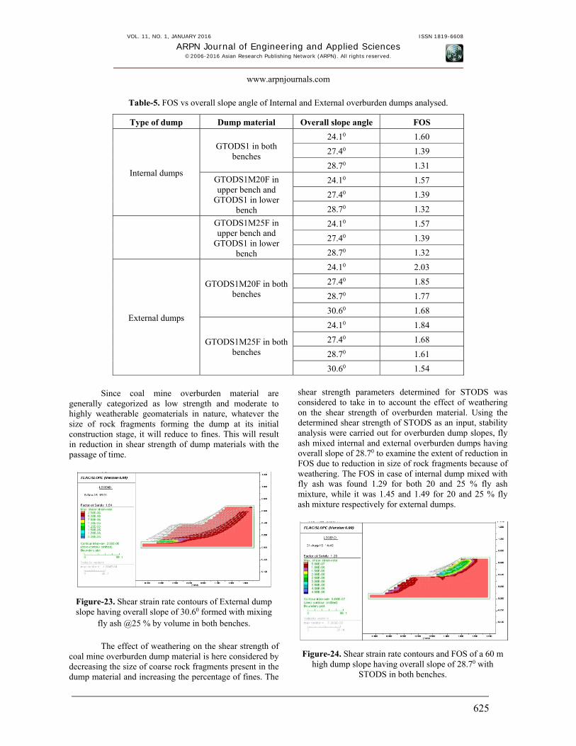
Table-5. FOS vs overall slope angle of Internal and External overburden dumps analysed.
Type of dump Dump material Overall slope angle FOS
Internal dumps
GTODS1 in both benches
24.10 1.60
27.40 1.39
28.70 1.31
GTODS1M20F in upper bench and
GTODS1 in lower bench
24.10 1.57
27.40 1.39
28.70 1.32
GTODS1M25F in upper bench and
GTODS1 in lower bench
24.10 1.57
27.40 1.39
28.70 1.32
External dumps
GTODS1M20F in both benches
24.10 2.03
27.40 1.85
28.70 1.77
30.60 1.68
GTODS1M25F in both benches
24.10 1.84
27.40 1.68
28.70 1.61
30.60 1.54
Since coal mine overburden material are
generally categorized as low strength and moderate to highly weatherable geomaterials in nature, whatever the size of rock fragments forming the dump at its initial construction stage, it will reduce to fines. This will result in reduction in shear strength of dump materials with the passage of time.
Figure-23. Shear strain rate contours of External dump slope having overall slope of 30.60 formed with mixing
fly ash @25 % by volume in both benches.
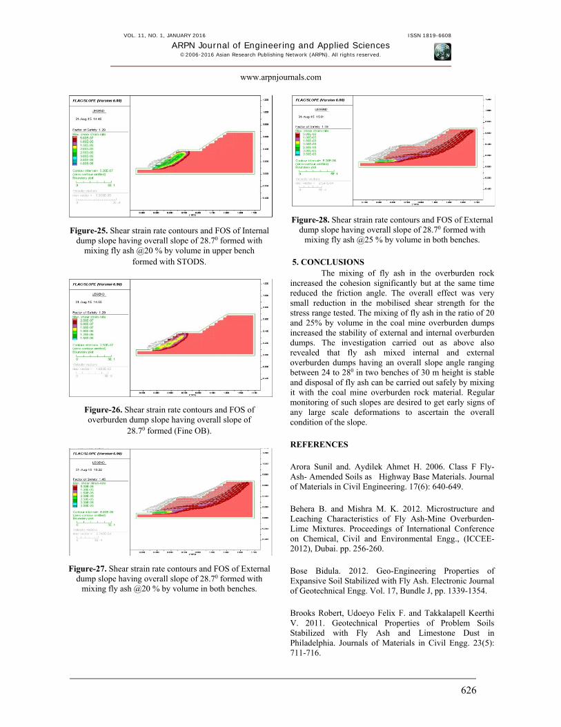
The effect of weathering on the shear strength of coal mine overburden dump material is here considered by decreasing the size of coarse rock fragments present in the dump material and increasing the percentage of fines. The
shear strength parameters determined for STODS was considered to take in to account the effect of weathering on the shear strength of overburden material. Using the determined shear strength of STODS as an input, stability analysis were carried out for overburden dump slopes, fly ash mixed internal and external overburden dumps having overall slope of 28.70 to examine the extent of reduction in FOS due to reduction in size of rock fragments because of weathering. The FOS in case of internal dump mixed with fly ash was found 1.29 for both 20 and 25 % fly ash mixture, while it was 1.45 and 1.49 for 20 and 25 % fly ash mixture respectively for external dumps.
Figure-24. Shear strain rate contours and FOS of a 60 m high dump slope having overall slope of 28.70 with
Figure-25. Shear strain rate contours and FOS of Internal dump slope having overall slope of 28.70 formed with
mixing fly ash @20 % by volume in upper bench formed with STODS.
Figure-26. Shear strain rate contours and FOS of overburden dump slope having overall slope of
28.70 formed (Fine OB).
Figure-27. Shear strain rate contours and FOS of External dump slope having overall slope of 28.70 formed with
mixing fly ash @20 % by volume in both benches.
Figure-28. Shear strain rate contours and FOS of External dump slope having overall slope of 28.70 formed with
mixing fly ash @25 % by volume in both benches. 5. CONCLUSIONS
The mixing of fly ash in the overburden rock increased the cohesion significantly but at the same time reduced the friction angle. The overall effect was very small reduction in the mobilised shear strength for the stress range tested. The mixing of fly ash in the ratio of 20 and 25% by volume in the coal mine overburden dumps increased the stability of external and internal overburden dumps. The investigation carried out as above also revealed that fly ash mixed internal and external overburden dumps having an overall slope angle ranging between 24 to 280 in two benches of 30 m height is stable and disposal of fly ash can be carried out safely by mixing it with the coal mine overburden rock material. Regular monitoring of such slopes are desired to get early signs of any large scale deformations to ascertain the overall condition of the slope. REFERENCES Arora Sunil and. Aydilek Ahmet H. 2006. Class F Fly-Ash- Amended Soils as Highway Base Materials. Journal of Materials in Civil Engineering. 17(6): 640-649. Behera B. and Mishra M. K. 2012. Microstructure and Leaching Characteristics of Fly Ash-Mine Overburden-Lime Mixtures. Proceedings of International Conference on Chemical, Civil and Environmental Engg., (ICCEE-2012), Dubai. pp. 256-260. Bose Bidula. 2012. Geo-Engineering Properties of Expansive Soil Stabilized with Fly Ash. Electronic Journal of Geotechnical Engg. Vol. 17, Bundle J, pp. 1339-1354. Brooks Robert, Udoeyo Felix F. and Takkalapell Keerthi V. 2011. Geotechnical Properties of Problem Soils Stabilized with Fly Ash and Limestone Dust in Philadelphia. Journals of Materials in Civil Engg. 23(5): 711-716.
Cambio Domenica and Ge Louis. 2007. Effect of parallel gradation on strength properties of ballast Material, Proceedings of Advances in Measurement and Modeling of Soil Behavior, Denver, Colarado. pp. 1-7. Cocka Erdal. 2001. Use of Class C Fly Ashes for the Stabilization of an Expansive Soil. Journal of Geotechnical and Geoenvironmental Engineering. 127(7): 568-573. Edil Tuncer B. and Benson Craig H. 2007. Sustainable Construction Case History: Fly Ash Stabilization of Road Surface Gravel. World of Coal Ash, Northern Kentucky, USA. pp. 1-12. Geliga Emilliani Anak and Ismail Dygku Salma Awg. 2010. Geotechnical Properties of Fly Ash and its Application on Soft Soil Stabilization, UNIMAS, E-Journal of Civil Engg. 1(2): 1-6. Ghanbari Ali, Sadeghpour Amir Hossien and Mohamadzadeh Masoud. 2008. An Experimental Study on the Behaviour of Rockfill Materials using Large Scale Tests, Electronic Journal of Geotechnical Engg. Vol. 13, Bundle G, pp. 1-16. IS: 2720 -Part 4. 1985. Indian Standard Methods of Test for Soils: Grain size analysis, Bureau of Indian Standards. IS: 2720 -Part 39, Section 1. 1979. Indian Standard Methods of Test for Soils: Direct Shear Test For soil containing gravel more than 4.75 mm size, Bureau of Indian Standards. IS: 10050. 1981. Indian Standard methods: Method for Determination of Slake Durability Index of Rock, Bureau of Indian Standards, New Delhi, India. pp. 1-7. IS: 2720- Part 7. 1980. Indian Standard Methods of test for soils: Determination of Water Content-Dry Density Relation Using Light Compaction. Bureau of Indian Standards, New Delhi, India. pp. 1-8. IS: 2720-Part-5. 1985. Indian Standard Methods of Test for Soils: Determination of Liquid and Plastic Limit, Bureau of Indian Standards, New Delhi, India. IS: 2720-Part 16, (1987) Indian Standard methods of test for soils: Laboratory Determination of CBR, Bureau of Indian Standards, New Delhi, India. pp. 1-15. IS: 2720-Part 3. 1980. Indian Standard Methods of test for soils: Determination of Specific gravity. Bureau of Indian Standards, New Delhi, India. pp. 1-8.
IS: 2720-Part 8. 1983. Indian Standard methods of test for soils: Laboratory Determination of Water Content-Dry Density Relation Using Heavy Compaction, Bureau of Indian Standards, New Delhi, India. pp. 1-9. IS: 8764. 1998. Indian Standard: Method for Determination of Point Load Strength Index of Rocks, Bureau of Indian Standards, New Delhi, India. pp. 1-10. Jayanthu S., Das Sarat K and Sk. Md. Equeenuddin. 2012. Stability of Fly Ash and Overburden Material in Opencast Mines- A Case Study. Proceedings of International Conference on Chemical Civil and Environmental Engineering (ICCEE’ 2012). pp. 276-278. Kim Bumjoo, Prezzi Monica and Salgado Rodrigo. 2005. Geotechnical Properties of Fly and Bottom Ash Mixtures for Use in Highway Embankments. Journal of Geotechnical and Geoenvironmental Engineering. 131(7): 914-924. Kumar M. Anjan, Prasad D. S.V. and Prasada Raju G. V. R. 2010. Performance Evaluation of Stablized Fly Ash Subbases. ARPN Journal of Engineering and Applied Sciences. 5(8): 50-57. Kumar Ritesh. 2010. Comparative Study of Leachate Characteristics of Pond Ash from Long-Term Leaching and Ash Pond Disposal Point Effluent from Chandrapura Thermal Power Station, India. E-Journal of Chemistry (http://www.e-journals.net). 7(S1): S131-S136, 1-6. Lowe John. 1964. Shear Strength of Coarse Embankment Dam Materials. Proceedings of 8th Congress on Large dams. pp. 745-761. Maiti S.K., Singh Gurdeep, Srivastava S.B. 2005. Study of the Possibility of Utilizing Fly Ash for Backfilling and Reclamation of Opencast Mines: Pilot and Field Scale Study with Chandrapura Fly Ash. Fly Ash Utilization Programme (FAUP), TIFAC, DST, New Delhi, India. pp. XII 31.1-31.13. Martin Joseph P., Collins Robert A., Browning John S. and Bieh Francis J. 1990. Properties and Use of Fly Ashes for Embankments. Journal of Energy Engineering. 116(2): 71-86. Ministry of Environment and Forest Notification, 3rd Nov. 2009. The Gazette of India: Extraordinary Part II, Section 3 (ii), New Delhi, Govt. of India. Ministry of Power, Central Electricity Authority (CEA), (August 2014), Annual Report. pp. 01-12.
Okunade Emmanuel Akintunde. 2010. Geotechnical Properties of Some Coal Fly Ash Stabilized Southwestern Nigeria Lateritic Soils. Modern Applied Science. 4(12): 66-73. Pandian NS. 2004. Fly ash characterization with reference to geotechnical applications. J. Indian Inst Sci. 84: 189-216. Phani Kumar B.R. and Sharma Radhey S. 2004. Effect of Fly Ash on Engineering Properties of Expansive Soils. Journal of Geotechnical and Geoenvironmental Engineering. 130(7): 764-767. Porbaha A., Pradhan T.B.S, and Yamane N. 2000. Time Effect on Shear Strength and Permeability of Fly Ash. Journal of Energy Engineering. 15: 15-31. Pradhan S.P., Vishal V, Singh T.N., Singh V.K. 2014. Optimisation of dump slope geometry vis-a-vis fly ash Utilization using numerical simulation. American Journal of Mining and Metallurgy. 2(1): 1-7. Prabakar J., Dendorkar Nitin and Morchhale R.K. 2004. Influence of Fly Ash on Strength Behavior of Typical Soils. Construction and Building Materials. 18: 263-267. Santos Fabio, Li Lin, Li Yadong and Amini Farshad. 2011. Geotechnical Properties of Fly Ash and Soil Mixtures for Use in Highway Embankments. Proceedings of World of Coal Ash Conference. pp. 1-11. Sarode Dhananjay Bhaskar , Jadhav Ramanand Niwratti, Vasimshaikh Ayubshaikh Khatik, Ingle Sopan Tukaram, Attarde Sanjay Baliram. 2010. Extraction and Leaching of Heavy Metals from Thermal Power Plant Fly Ash and its Admixtures. Polish J. of Environ. Stud. 19(6): 1325-1330. Sevi Adam F. 2008. Physical Modelling of Rail Road Ballast Using the Parallel Gradation Scaling Technique within the Cyclical Triaxial Framework. PhD Thesis, Missouri University of Science and Technology. pp. 7-13. Sharma Neeraj Kumar, Swain S.K., Sahoo Umesh C. 2006. Stabilization of a Clayey Soil with Fly Ash and Lime: A Micro Level Investigation. Journal of Geotechnical and Geological Engineering. 24(2): 1-11. Singh Gurdeep. 2005. Environmental Assessment of Fly Ash from Some Thermal Power Stations for Reclamation of Mined Out Areas. Fly Ash Utilization Programme (FAUP), TIFAC, DST, New Delhi, India. pp. IV 9.1-9.10. Singh T.N. 2011. Assessment of Coal Mine Overburden Dump Behaviour Using Numerical Modeling. Proceedings
of Rock Mechanics, Fuenkajorn and Phien-wej (eds). pp. 25-36. Sitharam T.G. and Nimbkar M.S. 2000. Micromechanical Modelling of Granular Material: Effect of Particle Size and Gradation. Journal of Geotechnical and Geological Engineering. 18: 91-117. Snigdha Sushil and Vidya S. Batra. 2006. Analysis of Fly Ash Heavy Metal Content and Disposal in Three Thermal Power Plants in India. Published by Elsevier Ltd. pp. 1-4. Takhelmayum Gyanen, Savitha A.L, Krishna Gudi. 2013. Laboratory Study on Soil Stabilization Using Fly Ash Mixtures. International Journal of Engineering Science and Innovative Technology (IJESIT). 2(1): 477-482. Tannant DD, Kumar V. 2000. Properties of fly ash stabilized haul road construction materials . Int J Surf Min Reclam Environ. 14: 121-135. Ugbe Felix C. 2011. Effect of Multicyclic Compaction on Cohesion in Lateritic Soils. Archives of Applied Science Research. 3(3): 115-121. Varadarajan A., Sharma K.G., Abbas S.M. and Dhawan A.K. 2006. Constitutive Model for Rockfill Materials and Determination of Material Constants” International Journal of Geomechanics. 6(4): 226-237. Varadarajan A., Sharma K. G., Venkatachalam K. and Gupta A. K. 2003. Testing and Modeling of Two Rockfill Materials. Journal of Geotechnical and Geoenvironmental Engineering. pp. 206-218. Yoon Sungmin, Balunaini Umashankar, Yildirim Irem Z., Prezzi, Monica and Siddiki Nayyar Z. 2009. Construction of an Embankment with a Fly and Bottom Ash Mixture: Field Performance Study. Journal of Materials in Civil Engineering. 21(6): 271-278.