Shearing interferometer as an interferometric filter for the reduction of scattered light H. A. Hill, P. T. Ballard, J. W. Figoski, and T. P. Caudell The background radiation problem encountered in astronomical observations is reviewed, and it is observed that a considerable reduction of the background radiation can be achieved by using interferometric tech- niques. A longitudinal radial shearing interferometer is described which meets the requirements of this ap- plication. The formal development of its properties as well as the results of preliminary tests are presented. It is shown that for a small region of the telescope field, this interferometer can be expected to reduce the background radiation originating in the telescope by a factor of 50 to 500,to reduce the background radiation produced by Mie type scattering external to the telescope to a level belowthat produced by Rayleigh scatter- ing, and to reduce the background radiation from Rayleigh scattering by a factor of two. These properties can be extended to broadband spectral operation and can be achieved without degrading the astrometric qualities of the telescope. The size of the interferometer is quite small making it easy to add to an existing telescope. 1. Introduction The presence of unwanted radiation in astronomical measurements has always placed constraints on the effective information gathering abilities of an instru- ment. This problem not only plagues the daytime as- tronomer but also limits the nighttime astronomer as well. An extensive reexamination of this problem has been made, looking for the possible advances that might be achieved with the introduction of interferometric techniques. To this end we have found a member of the class of radial shearing interfrometers which filters the incoming radiation as a function of longitudinal source position. That is, the transmission coefficient is high for certain source locations and low for others. We further find that this interferometric filter does not degrade the astrometric properties of a particular in- strument. These properties will then allow, for exam- ple, the daytime astromet to measure with greater ac- curacy star positions within a few solar radii from the sun's limb, and will extend the magnitude limit of the nighttime astronomer who is restricted by city limits or the glare of the moon. The properties of this interferometer, as well as the results of tests demonstrating these properties, are given in the following sections. In addition, the background radiation problem is reviewed so that the problem as it The authors are with University of Arizona, Tucson, Arizona 85721. J. W. Figoski is with the Optical Sciences Center; the other authors are with the Physics Department. Received 8 May 1976. presently exists can be clearly stated. This serves two purposes. First, it points the way to the natural in- clusion of interferometric techniques in this area, and second, it furnishes the information used to establish the specifications for an interferometric filter. II. Sources and Magnitude of Background Radiation A knowledge of the sources and magnitudes of background radiation is necessary to define the back- ground radiation problem and to judge the success of the particular compensating system. It is with this in mind that the sources and the associated magnitudes of background radiation are reviewed. Sources of background radiation may be classified into two categories, external and internal, which are easily distinguished by the location of the scattering center. The predominant source of external back- ground arising from large angle scattering is atmo- spheric Rayleigh scattering resulting in the familiar blue sky. It is also a significant source of background on a moonlit night. The predominant source of external background arising from small angle scattering is due to Mie scattering from particulates and aerosols sus- pended in the lower atmosphere causing the familiar haze. 1 Note also that the presence of insects in the at- mosphere contributes significantly to this problem. These external sources of small angle scattering are partially removed by placing the observatory on a mountain top above a large fraction of the material. However, as reported by Newkirk,' substantial quan- tities of particulates and aerosolsstill remain even at the January 1977 / Vol. 16, No. 1 / APPLIED OPTICS 195
Transcript
Shearing interferometer as an interferometric filter for thereduction of scattered light
H. A. Hill, P. T. Ballard, J. W. Figoski, and T. P. Caudell
The background radiation problem encountered in astronomical observations is reviewed, and it is observedthat a considerable reduction of the background radiation can be achieved by using interferometric tech-niques. A longitudinal radial shearing interferometer is described which meets the requirements of this ap-plication. The formal development of its properties as well as the results of preliminary tests are presented.It is shown that for a small region of the telescope field, this interferometer can be expected to reduce thebackground radiation originating in the telescope by a factor of 50 to 500, to reduce the background radiationproduced by Mie type scattering external to the telescope to a level below that produced by Rayleigh scatter-ing, and to reduce the background radiation from Rayleigh scattering by a factor of two. These propertiescan be extended to broadband spectral operation and can be achieved without degrading the astrometricqualities of the telescope. The size of the interferometer is quite small making it easy to add to an existingtelescope.
1. Introduction
The presence of unwanted radiation in astronomicalmeasurements has always placed constraints on theeffective information gathering abilities of an instru-ment. This problem not only plagues the daytime as-tronomer but also limits the nighttime astronomer aswell. An extensive reexamination of this problem hasbeen made, looking for the possible advances that mightbe achieved with the introduction of interferometrictechniques. To this end we have found a member of theclass of radial shearing interfrometers which filters theincoming radiation as a function of longitudinal sourceposition. That is, the transmission coefficient is highfor certain source locations and low for others. Wefurther find that this interferometric filter does notdegrade the astrometric properties of a particular in-strument. These properties will then allow, for exam-ple, the daytime astromet to measure with greater ac-curacy star positions within a few solar radii from thesun's limb, and will extend the magnitude limit of thenighttime astronomer who is restricted by city limits orthe glare of the moon.
The properties of this interferometer, as well as theresults of tests demonstrating these properties, are givenin the following sections. In addition, the backgroundradiation problem is reviewed so that the problem as it
The authors are with University of Arizona, Tucson, Arizona 85721.J. W. Figoski is with the Optical Sciences Center; the other authorsare with the Physics Department.
Received 8 May 1976.
presently exists can be clearly stated. This serves twopurposes. First, it points the way to the natural in-clusion of interferometric techniques in this area, andsecond, it furnishes the information used to establishthe specifications for an interferometric filter.
II. Sources and Magnitude of Background Radiation
A knowledge of the sources and magnitudes ofbackground radiation is necessary to define the back-ground radiation problem and to judge the success ofthe particular compensating system. It is with this inmind that the sources and the associated magnitudesof background radiation are reviewed.
Sources of background radiation may be classifiedinto two categories, external and internal, which areeasily distinguished by the location of the scatteringcenter. The predominant source of external back-ground arising from large angle scattering is atmo-spheric Rayleigh scattering resulting in the familiar bluesky. It is also a significant source of background on amoonlit night. The predominant source of externalbackground arising from small angle scattering is dueto Mie scattering from particulates and aerosols sus-pended in the lower atmosphere causing the familiarhaze.1 Note also that the presence of insects in the at-mosphere contributes significantly to this problem.These external sources of small angle scattering arepartially removed by placing the observatory on amountain top above a large fraction of the material.However, as reported by Newkirk,' substantial quan-tities of particulates and aerosols still remain even at the
typical elevation of telescope sites, i.e., 2-3 km. For thisreason Mie scattering remains the predominant sourceof background near a bright source such as the sun ormoon.
Lyot2-4 identified five principal sources of internalbackground radiation which are (1) diffraction at theentrance pupil of the telescope, (2) multiple reflectionin the optics causing unfocused images on the primaryfocal plane, (3) macroscopic defects within the glass(bubbles, striae, etc.), (4) microscopic defects in theglass, and (5) surface defects (scratches, dust, or poorpolish). He was able to remove diffraction effects byimaging the objective onto an occulting stop, removingthe first- and higher-order bright diffraction rings. Tocompensate for spurious images due to multiple re-flections, he placed a small occulting disk in the secon-dary field of the telescope blocking the unwanted im-ages. The reduction of the remaining sources rested inchoosing suitable material for the telescope optics suchthat they too were minimized. By these techniques,Lyot demonstrated that it was possible to design atelescope with an image field irradiance of approxi-mately 5 X 10⁻⁶ that produced by the mean solar disk.Since the net irradiance from the sky is nearly 10-5 ata good site, diminishing the instrumental scatter furtherwould serve little purpose.
Finally, with respect to surface imperfections in thesystem, continuous maintenance of the optics is essen-tial if the ideal situation is to be achieved. In manytelescopes this is a tedious and, in most cases, a difficulttask to perform correctly if further damage to the sur-faces is to be avoided. Therefore, there is a strongtendency for the telescope to be operated at somethingless than its optimum capabilities. This may meanoperating with an internally produced background of10-5-10-4 of the mean solar disk.
Thus the problem presented by the scattering sourcesmay be summarized as follows:
External sources: the Mie scattered radiation orig-inates within a few kilometers of the telescope, whereasthe Rayleigh scattered radiation drops off with a scaleheight of 8 km.1 It is the latter which imposes the mostdifficult source to remove because of its extended rangein the object space.
Internal sources: the optical and mechanical com-ponents of the measuring instrument itself give rise tothe largest amount of scattered light for daytime work.These sources need to be reduced by a factor of 50 to 500in order to achieve an irradiance level significantlybelow that which is set by the external sources.
The problem of how to achieve this reduction of thescattered light is presented in the next section.
111. Reducing the Effect of the Scattered Light
Considerable progress has been made in the generalreduction of this background radiation with the classicwork of Lyot described in Sec. II and the more recentwork of Newkirk and Bohlin.5 With one exception, thework subsequent to Lyot's has been for the most part
refinement of his work without introducing any signif-icant new techniques. The one exception has been theintroduction of external stops by Newkirk and Boh-lin.
The background flux which remains after the appli-cation of these various techniques must still be mea-sured independently in the telescope field and then, bymeans of extrapolation or interpolation to the region ofinterest, subtracted from the total flux containing thedesired signal and unwanted radiation. Although thisdoes permit the removal of the systematic errors, it doesnot reduce, but actually increases, the statistical errorthat defines the range of meaningful applications for aparticular instrument, and it is the reduction of thisstatistical error that is the problem to be solved.
It is this statistical error, for example, which deter-mines the ultimate accuracy of the astrometric obser-vations at SCLERA6 where a program is under way tomeasure the gravitational deflection of star light by thesun.7'8 A factor of 10 reduction in this statistical errorwould permit observations with msec of arc accuracy ofsixth magnitude stars near the sun. It was this poten-tial of the observational program at SCLERA that ac-tually motivated the search for a solution to this prob-lem. The initial work and the actual identification ofthe resolution of the problem are credited to two of theauthors (H. Hill and P. Ballard).
In the above discussion, the reduction of systematicerrors without reducing the statistical errors arises fromthe fact that the background correction is made bysubtracting intensities. That is, the number of photonsdetected in one part of the field is subtracted from thenumber detected at a different location. However, thesimultaneous reduction of the statistical and systematicerrors can be achieved if, instead of subtracting inten-sities, the amplitudes of each scattered photon aresubtracted. This is the physics which strongly suggeststhat interferometric techniques should be introducedto solve the problem.
The information needed to reach the solution is alsoquite accessible. The wavefront produced by a scat-tering center in the atmosphere or at the telescope hasa structure inherently different from that produced bya star. The wavefront of the scatterer is spherical, whilethat of the star is planar. In the focal plane of thetelescope the wavefront of the stellar photon will belocalized in a very small region, while the wavefront ofthe scattered photon will be spread over a large extent,i.e., it is out of focus. The design of an interferometerwhich distinguishes between these two wavefrontcharacteristics is the solution we are after.
The goals for this interferometer, in terms of howmuch reduction is needed, are set by the types of scat-terers discussed in Sec. II. It was mentioned that, at anelevation of a few kilometers above the observation site,the density of particulate matter, aerosols, and insectsis sufficiently low that the Rayleigh scattering is thedominant background source. This is independent ofthe relative location of a bright object and the point ofobservation in the sky. Consequently, one design goalthat would be quite significant would be the removal ofthe background radiation from sources which are lo-
cated below an elevation of 6 km, i.e., an elevation 3 kmabove the typical telescope site. Should this goal beattained, the remaining external background irradiancewould be about 4 X 10⁻⁷ of the mean solar disc.1 9 Sincethe scale height for the atmosphere is 8 km it is apparentthat any further significant gains in the Rayleigh scat-tering are achieved slowly. Consequently, this level of4 X 10-7 also establishes the practical design goal for thereduction of internally produced background radiationas well.
It should be noted that, although the design goal thatis chosen for the compensated background level is onlya factor of 10 better than the best achieved by Lyot, itnonetheless represents a considerable improvement.This is particularly true when one realizes that this newlevel of operation can be achieved for a telescope thatis not maintained in a state-of-the-art low scatteringcondition.
IV. A Shearing Interferometer
Radial and lateral shearing interferometers arecommonly used to test the figure of a wavefront.10
Their application to background compensation may bethought of as actually an optical testing exercise. Asnoted in Sec. III there are significant differences in thewavefronts originating from a star and a scatteringcenter. The shearing interferometer is used in this caseto test the wavefront and identify its origin. There arevarious ways that this testing may be performed.
The test could be done in a manner suggested by thebackground correcting scheme discussed in Sec. III.The technique described was to sample the backgroundintensity at specific points and then, by extrapolatingto the region of interest, subtract the background toobtain the desired signal. Now if background com-pensation is considered from the point of view of in-terferometry, the process analogous to this is classifiedas lateral shearing interferometry. In this case thewavefront amplitudes would be shifted with respect toeach other and the lateral shear introduced would bechosen sufficiently large so that the localized amplitudeof the stellar image does not destructively interfere withitself. However, lateral shearing interferometers ingeneral exhibit one peculiarity which will not allow theiruse in this application. The problem is that a changein the angle of incidence of the wave into the interfer-ometer will produce a change in the optical path dif-ference between the two emerging wavefronts that isproportional to the change in the angle of incidence andto the lateral shear. Thus on-axis and off-axis back-ground radiation cannot both be compensated simul-taneously.
The class of radial shearing interferometers exhibitsan analogous property. Fortunately, the optical pathdifference in this case is a function of more parameters,i.e., there are more degrees of freedom. Thus a radialshearing interferometer affords a possible solution tothe background reduction problem. The two emergingwavefronts in a pure radial shearing interferometer havedifferent radial magnifications and are not shifted lat-erally relative to each other. However, as one moves offaxis, the location of the point at which no relative shift
BEAM SPLITTER
FI ELDLENS
BEAM SPLITTER
AUXILIARYCELLS
EXIT PINHOLE
Fig. 1. Isometric view of the radial shearing interferometer. Itconsists of a Mach-Zehnder interferometer with additional auxiliary
lens cells in each leg and a field lens in front.
occurs does depend on the angle of incidence of the waveand the details of the interferometer itself (the extradegree of freedom). To be of any practical value, thispoint must be stationary at some location in the imagespace, i.e., at the exit pinhole. Taking advantage of theextra degree of freedom, a design for a radial shearinginterferometer has been found which does exhibit thisstationary property for any source located on a prese-lected plane of the object space. This particular in-terferometer has properties similar to a longitudinalradial shearing interferometer in that the twoemerging wavefronts diverge from two different points.In our particular application of this interferometerthough, the emerging wavefronts have the same opticalpath except for a 1800 phase shift. This phase shift isintroduced in order that the central fringe is a null at theexit pinhole.
A broad null fringe at the pinhole is obtained for thescattering centers since they are imaged by the systemat a location far from the exit pinhole. However, theinterferometer images a star as two points close to theexit pinhole, and the resulting fringe pattern is a highlycondensed pattern of concentric circles entirely con-tained within the exit pinhole. It is the size differencein the fringe pattern that is used to distinguish betweenthe different origins of the waves in the object space.
This interferometer is shown in Fig. 1. It consists ofa Mach-Zehnder interferometer with additional auxil-iary lens cells in each leg and a field lens in front. Therole of the field lens in this case is to map as best aspossible the external and internal sources of backgroundradiation into the preselected plane identified in theabove discussion. In the application studied here, thefield lens is located close to the primary focal plane ofthe telescope and the exit pinhole is positioned at adistance essentially equal to the principal focus of thefield lens. The auxiliary lenses are used to image thestar and scatterers in the desired manner.
The intensity of the stellar image will be dividedequally between the two exit beams of the interferom-eter as a result of the interference occurring in the stellarimage at the exit pinhole. Nonetheless, the preferentialreduction of the unwanted radiation is still achieved.A telescope fully implemented for reduction of scatteredlight by the use of Lyot techniques also has a trans-mission of about 50%. Consequently the replacementof an instrument using Lyot techniques with one using
this radial shearing interferometer results in no furtherreduction of signal, while, as shown in Appendix C, itis possible to achieve a considerable improvement in thereduction of background radiation for a small area of thefield.
Other assets of the radial shearing interferometer arethat it is possible to incorporate it into an instrumentwith a minimum of mechanical problems and that thiscan be done in such a way so as not to degrade the as-trometric qualities of a particular telescope. This is,however, not the case with the incorporation of the Lyottechniques or the external stops of Newkirk and Bohlin.The Lyot techniques require multiple optical elementswhich in general are widely separated. Zanoni andHill12 have observed that because of this, such tech-niques are difficult to incorporate into an astrometricinstrument and still maintain its astrometric qualities.On the other hand, the external stop technique presentsmechanical problems. For example, to observe within2 min of arc of the solar disk with a 15-cm aperture, thefirst external occulting disk must be located 262 m awayfrom the objective.
The formal development of the mathematical rela-tionships for the interferometer is given in the Appen-dices. The mathematical relationships derived thereare the basis for the specifications of the system pa-rameters as well as for evaluating the merits of a specificconfiguration.
It is concluded from the results of Appendices C andD that the design goal of a background of 4 X 10⁻⁷ givenin Sec. III is achievable in monochromatic light. Be-cause of the symmetry and simplicity of the configura-tion it is anticipated that the design can be refined toexhibit such properties in white light as well.
V. Demonstration of Feasibility
The general constraint equations which define theradial shearing interferometer are described in Ap-pendix A. In addition to these, particular solutions arefound and given in Appendix B. These solutions arerequired for two reasons. First, they demonstrate thatthere exist practical solutions to the constraint equa-tions, and second, they provide the specifications for aninterferometer whose properties can be examined ex-perimentally and compared with theoretical predic-tions.
An interferometer was fabricated with off-the-shelf,commercial optics which met the specifications of thesecond solution given in Appendix B. This system,however, did not meet the necessary requirements withregard to tolerances on the figures of the transmittedwavefronts as discussed in Appendix D. Nonethelessit was possible to demonstrate the essential features ofthe interferometer with this optical system.
The two essential features are, first, the stationaryproperty of the dark fringe for a scattering center lo-cated in the preselected plane, and, second, the con-densation of the interference pattern into the exit pin-hole for a wave simulating one originating from a star.For the first test, the scattering center and scatteredwave were simulated by the diverging wave from a fo-cused laser beam (632.8 nm). The source was located
on the stationary plane as defined by the chosen optics.It was then moved to various positions off axis. Thelocation of the dark fringe was found to be stationaryto better than one quarter of a fringe over a 0.250 en-trance cone. This is to be compared to the motion ofthe dark fringe typically found in radial shearing in-terferometers of several fringes.
The second test was performed by simulating thestellar image in the focal plane of the telescope with thesame focused laser beam. In this case the location ofthe source was moved from the preselected plane to theequivalent focal plane of the telescope. In this instancethe complex image produced by the interferometer wasat the exit pinhole and contained in the pinhole.
The main limitation in these two tests was obviouslythe quality of the interferometer optics. Nonetheless,the results clearly demonstrate that the principles in-volved in this interferometer are well understood.
VI. Applications
As one would expect, the background compensatorhas a wide spectrum of applications, the daytime lightbending experiment (see Sec. III) being only one. Therealization that diffuse as well as point sources willconstructively interfere within the canceled backgroundlight leads to several interesting examples. We willlimit this discussion to astronomical applications only,although a field such as laser communications mightalso benefit.
One astronomical object that may be studied only inthe daytime is the solar corona. The time available forstudy has in the past been limited to total solar eclipsesand, after the development of the coronagraph, limitedto heights beyond the limb of less than one half of a solarradius. The limitation is clearly due to instrumentaland atmospheric scattering. When this scattering isreduced, the corona could be examned out to greaterheights, perhaps two or three solar radii.9
In the preceding sections it was assumed that eitherone technique was used or the other. That is, either theuse was made of the Lyot techniques and external oc-culting disks or the radial shearing interferometer.However, in those situations where external occultingdisks can be conveniently used, the combination of thesedisks and the radial shearing interferometer offer evengreater potential in gains. In the use of external oc-culting disks, the diffracted light produced by thesedisks is the limiting factor. However, this remainingbackground can be reduced further by the interferom-etric techniques.
The compensator provides additional advantages inthe light bending experiment. While for a given starthe SNR may be improved by a factor of 10, for a givenminimum acceptable SNR the number of stars availablefor measurement increases by a factor of 50. Thus thisimprovement in statistics will permit partial reductionof systematic errors which arise due to the small sampleof objects presently available for study.
The nighttime astronomer has background limitsalso. On a clear moonless night, far away from the city,the magnitude limit is set by upper atmospheric skyglow and by integrated diffuse starlight in the galaxy.
But due to scattering in the instrument and near at-mosphere this limit can be reached only with greatdifficulty. Scattered moonlight interferes with nearlyone half of observing time at the telescope. Suburbansprawl steadily encroaches on even the most remoteobservatory site, making light pollution one of the mostserious problems facing astronomers today. Obviouslya reduction in background light would allow the recov-ery of precious telescope time.
Another place where observations are limited, inmuch the same way as daytime observations, is ir as-tronomy. In this case, an additional source of back-ground radiation is the thermal radiation from thetelescope objective and the sky. A considerable re-duction of this radiation in the near ir should be possiblewith the incorporation of the radial shearing interfer-ometer in the telescope.
Although the above discussion is not quantitativewith regard to various applications, it is apparent thatsuch a device should afford considerable gains in manyareas of astronomy.
VII. Summary
A discussion of the sources and magnitudes of thebackground radiation problem in the context of limitingdaytime and nighttime astronomical observations, alongwith a new technique for the reduction of this back-ground, has been presented. Until now, any reductionbeyond that obtained by some correction scheme reliedupon the technique of subtracting intensities. Thedrawback to this method is that it does not reduce thestatistical errors.
The new solution which we present uses interferom-etric techniques to reduce the amplitude of the scatteredwavefront and thus reduce both systematic and statis-tical errors at the same time. In addition, the desiredsignal from a star is allowed to pass through withoutdegrading the astrometric qualities of the instrument.A formal development of the mathematics used to de-scribe this system is given in the Appendices, and it isshown that a reduction of the scattered light to a levelof 4 X 10⁻⁷ of the irradiance levels of the solar image canbe achieved over a limited region of the telescope field.A graph is presented which shows the preferentialcancellation for scatterers in a preselected plane andsignificant cancellation for distances out to about 4 kmbeyond the telescope objective.
The authors acknowledge the helpful discussions withR. T. Stebbins, T. M. Brown, and F. M. Smolka and thecontributions of E. Wainright in performing the pre-liminary test. This work was supported by the NationalScience Foundation.
q sLENS -!"LENS 2
f~~~~~~ p< 02~~~?f+E
L
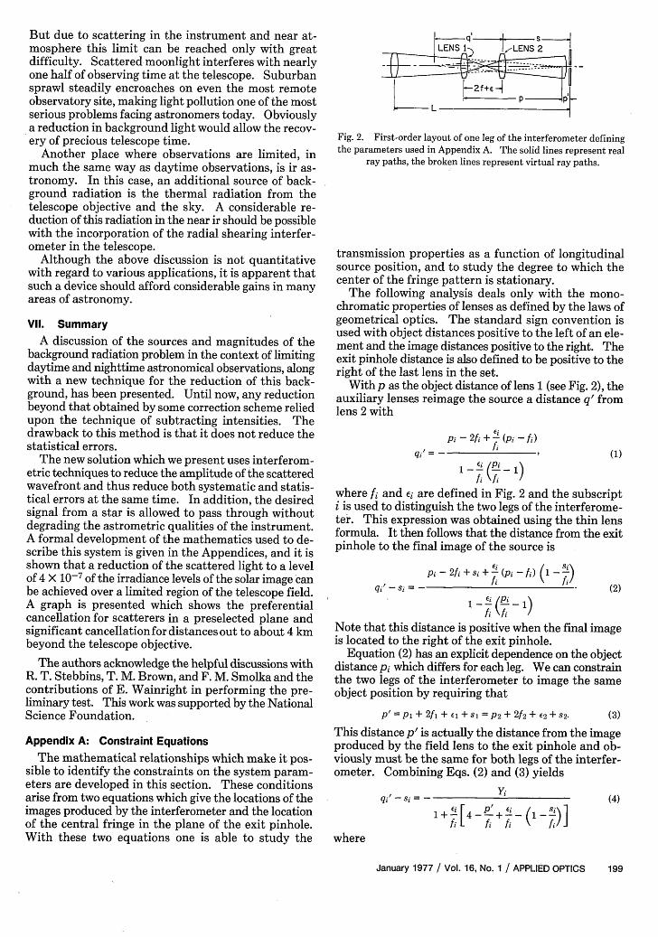
Fig. 2. First-order layout of one leg of the interferometer definingthe parameters used in Appendix A. The solid lines represent real
ray paths, the broken lines represent virtual ray paths.
transmission properties as a function of longitudinalsource position, and to study the degree to which thecenter of the fringe pattern is stationary.
The following analysis deals only with the mono-chromatic properties of lenses as defined by the laws ofgeometrical optics. The standard sign convention isused with object distances positive to the left of an ele-ment and the image distances positive to the right. Theexit pinhole distance is also defined to be positive to theright of the last lens in the set.
With p as the object distance of lens 1 (see Fig. 2), theauxiliary lenses reimage the source a distance q' fromlens 2 with
qi' = -
Pi- 2fi +- (pi -fi)fi
(1)
where fi and Ei are defined in Fig. 2 and the subscripti is used to distinguish the two legs of the interferome-ter. This expression was obtained using the thin lensformula. It then follows that the distance from the exitpinhole to the final image of the source is
Si Pi - 2 i + si + - (pi - ) 1 - I)
_~~~~f fiqi' - si = (2)
Note that this distance is positive when the final imageis located to the right of the exit pinhole.
Equation (2) has an explicit dependence on the objectdistance pi which differs for each leg. We can constrainthe two legs of the interferometer to image the sameobject position by requiring that
P'= PI + 2fl + l + S = P2 + 2f2 + E2 + S2. (3)
Appendix A: Constraint Equations
The mathematical relationships which make it pos-sible to identify the constraints on the system param-eters are developed in this section. These conditionsarise from two equations which give the locations of theimages produced by the interferometer and the locationof the central fringe in the plane of the exit pinhole.With these two equations one is able to study the
This distance p' is actually the distance from the imageproduced by the field lens to the exit pinhole and ob-viously must be the same for both legs of the interfer-ometer. Combining Eqs. (2) and (3) yields
Equation (4) is the first of the two equations which willbe used to evaluate the transmission properties of theinterferometer.
For the study of the degree to which the fringe pat-tern is stationary, one needs to know the angle of inci-dence Oi of the incoming waves. The tangent of is angleis given by
tanOi= hi' ()qi' - s
where hi' is the final image height produced by the in-terferometer. This can be put in terms of the objectheight h and qi' - si of Eq. (4) to give
tanOi = - - (6)Yi
The height h is defined for the scatterer with the objectdistance p.
The requirement that the central fringe be stationaryas the source is moved off axis is satisfied when
tanO1 = tanO2. (7)
Since the off-axis distance h is the same for the two legs,the consequence of Eq. (7) is to require that the de-nominator of Eq. (6) be invariant. That is, it must bethe same for the two legs of the interferometer. Sincethis leads to an equation which is linear in p', there doesexist in general, a solution that is real. That is, thereexists a p' for which the location of the central fringe atthe exit pinhole is independent of the off-axis sourceposition. This is the property that is desired.
For two equal amplitude spherical waves, the re-sulting intensity distribution in the interference patternis
Ii = o(l + cosaj), (8)
where Io is the intensity of the individual waves, aj isthe phase difference between the two waves, and thesubscript j refers to the two output paths of the inter-ferometer. The compensated output, = 1 is at the exitpinhole, and its complement j = 2, follows the otherroute through the beam splitter. The values of aj canbe shown to be
a = r + r [(2 )]
and (9)a2 = aYi - r
where r is the radial distance out from the center ofthe pattern. and R1 and R2 are the respective radii ofcurvature of the spherical waves. This is valid for r <<Ri. Note that in Eq. (9) we have introduced a 7r phaseshift in leg one in order to achieve a dark centralfringe.
Therefore
II= o 1 - cos r > kR2 RP ] J, (10)
where the radii Ri are given by Eq. (3), i.e., Ri = qi' -si. Thus it is possible to calculate the transmission ofthe system for a particular configuration.
The transmission T for the interferometer is obtainedby integrating I, uver the exit pinhole and normalizingit to the total energy in both output paths. This can bestated as
J'IldxdyT = , ~~~~~~~~(11)
X (II + I 2)dxdy
where A denotes the area of the pinhole. For the casewhere the central fringe remains on axis, this can beintegrated yielding
T = 1h (1 - sinc at0 2), (12)
where 40 is the radius of the exit pinhole, a = 7r/X(1/R2-1/R1) and sinc a O = (sin at2)/a O.
It is obvious on examination of Eq. (12) that the de-sired transmission properties are obtained when at «1 for the scattered wave and a 4 > 1 for the unscatteredwave. In other words, the q' - s given by Eq. (4) mustbe large and approximately the same size when p' cor-responds to the preselected plane and when p' ischanged to that corresponding to a star, the q' - simust become small and maintain a finite difference. Asolution to this constraint does exist and is demon-strated by the examples given in Appendix B and thecorresponding transmission properties given in Ap-pendix C.
Appendix B: Solutions
Two solutions which satisfy the constraints imposedin Appendix A are listed in Table I. The notation usedin the table is the same as that used in Appendix A andFig. 2. These solutions are given for several reasons.First, their existence demonstrates that solutions doexist. Second, a solution (solution 1) has been foundthat meets the requirements of the SCLERA facility.The degree to which they are met is shown in AppendixC. Thus solution 1 demonstrates that there are solu-tions that not only satisfy the constraints but also so-lutions which do offer a considerable improvement inthe reduction of the background radiation. Third, asecond solution (solution 2) has been found which isbuilt around off-the-shelf optical components. Thisis the solution that was used in feasibility studies dis-cussed in Sec. V.
The transmission properties of the interferometricfilter are given by Eq. (12) when the central fringe re-mains on axis. But, as noted in Appendix A, the fringepattern is stationary only for sources in one particularplane of the object space. Thus Eq. (12) is not valid ingeneral. However, Eqs. (101 and (11) remain valid aslong as proper expressions for the quantity r are used.That is, for each contributing point of the object space,r is the distance from the center of the fringe pattern tothe point of observation t in the exit pinhole field.
An expression for the intensity at the point of ob-servatin t in the exit pinhole field was obtained, takinginto account the motion of the fringe pattern using thelaws of geometrical optics. For a given plane in theobject space which is characterized by p' and for a givenI, an expression for r was found, and the resulting I1given by Eq. (10) was averaged over the object space.For a 2 < 1, the averaged intensity (Ii) is given by(Ii) oa2
2
X [ (1 - Ot) + 242(1 - t3)2po20p2 + Io4 4] (13)
where
(Y2 Y) R2 1 (ff )
(Y2 Y) (2R)(t
Po = ff (d/fo),
and d and fo are the semiaperture and focal length ofthe telescope objective, respectively. The other pa-rameters are as defined in Appendix A.
The transmission T for the interferometer is foundby using Eqs. (11) and (13). This gives
where 40 is the radius of the exit pinhole.The transmission given by Eq. (14) was evaluated for
the SCLERA facility, where d/fo = 1/200, using the pa-rameters listed in solution 1. The results are plottedfor three different values of 40 in Fig. 3. The curves 1, 2,and 3 correspond to the exit pinhole diameter of 4.35 secof arc, 8.70 sec of arc, and 13.0 sec of arc, respectively.This figure clearly shows that the design goal of abackground of 4 X 10⁻⁷ given in Sec. III is quite feasi-ble.
One closing remark is relevant to Eqs. (13) and (14)in regard to the use of the laws of geometrical optics intheir derivation. For the SCLERA facility with a 12-cmaperture, diffraction effects give rise-to only small cor-rections to Eqs. (13) and (14) in the region of interest.
Appendix D: Tolerances on Figures of OpticalSurfaces
The transmission properties for the interferometricfilter which are shown in Fig. 3 were obtained assumingthat the optics in the system were ideal.' However, thereare problems presented by both the optical aberrations
Elevation (km)
C0
.Ewa
2 3p' (cm)
Fig. 3. The transmission of the interferometric filter as a functionof the source location relative to the telescope objective. The pa-rameterp' is shown in Fig.2 and defined by Eq. (3). The transmissioncurves 1,2, and 3 are for three different exit pinhole diameters of 4.35
sec of arc, 8.70 sec of arc, and 13.0 sec of arc, respectively.
and the figuring errors produced in the manufacture ofthe optical elements.
The optical aberrations, geometrical and chromatic,are not treated here and must wait for further work.However, it should be noted that the effect of theseaberrations well cancel out to a large extent because ofthe symmetry of the system.
The wavefront errors due to figuring errors in theoptics do not cancel in general and are judged the mostdifficult of the two problems. The transmission pro-duced by a small wavefront error of AW is to a goodapproximation
T= (or 2 (15)
For a T of 1/400, the figure of the individual wave mustbe good to X/60. This would normally be an extremelydifficult goal to achieve with a multielement system.However, this is required only over a very small region.For example, the diameter of the region in the SCLERAtelescope is 0.025 cm for a 4.35-sec of arc aperture.Because of this it should be possible to reach the abovetolerance level in the region of interest with X/20 op-tics.
References1. G. A. Newkirk, Jr., J. Opt. Soc. Am. 46, 1028 (1956).2. B. Lyot, C. R. Acad. Sci. 191, 834 (1930).3. B. Lyot, C. R. Acad. Sci. 193, 1169 (1931).4. B. Lyot, Mon. Not. R. Astron. Soc. 99, 580 (1939).5. G. Newkirk, Jr., and B. Bohlin, Appl. Opt. 2, 131 (1963).6. SCLERA is the acronym for the Santa Catalina Laboratury for
Experimental Relativity by Astrometry, a facility of the Uni-versity of Arizona and Wesleyan University.
7. C. A Zanoni, Ph.D. Thesis, Princeton University (1966).8. J. R. Oleson, C. A. Zanoni, H. A. Hill, A. W. Healy, P. D. Clayton,
and D. L. Patz, Appl. Opt. 13, 206 (1974).9. See, for example, H. Zirin, The Solar Atmosphere (Blaisdell,
Waltham, 1966); Sec. 6.3.10. Fouer6 and D. Malacara, Bol. Inst. Tonantzintla 1, 227 (1975).11. S. C. Som, Opt. Acta 17, 107 (1970).12. C. A. Zanoni and H. A. Hill, J. Opt. Soc. Am. 55, 1608 (1965).