Page 1
arX
iv:c
ond-
mat
/010
7563
v1 [
cond
-mat
.sof
t] 2
7 Ju
l 200
1
Under consideration for publication in J. Fluid Mech. 1
A frictional Cosserat model for the slow
shearing of granular materials
By L. SRIN IVASA MOHAN†, K. KESAVA RAO1, AND
PRABHU R. NOTT2
Department of Chemical Engineering, Indian Institute of Science
Bangalore 560 012, INDIA
e-mail: [email protected] , [email protected]
A rigid-plastic Cosserat model for slow frictional flow of granular materials, proposed
by us in an earlier paper, has been used to analyze plane and cylindrical Couette flow.
In this model, the hydrodynamic fields of a classical continuum are supplemented by the
couple stress and the intrinsic angular velocity fields. The balance of angular momen-
tum, which is satisfied implicitly in a classical continuum, must be enforced in a Cosserat
continuum. As a result, the stress tensor could be asymmetric, and the angular velocity
of a material point may differ from half the local vorticity. An important consequence of
treating the granular medium as a Cosserat continuum is that it incorporates a material
length scale in the model, which is absent in frictional models based on a classical con-
tinuum. Further, the Cosserat model allows determination of the velocity fields uniquely
in viscometric flows, in contrast to classical frictional models. Experiments on viscomet-
ric flows of dense, slowly deforming granular materials indicate that shear is confined
to a narrow region, usually a few grain diameters thick, while the remaining material
is largely undeformed. This feature is captured by the present model, and the velocity
† Currently at Fluent India Pvt. Ltd., South Koregaon park, Pune 411 001, India
Page 2
2 L. S. Mohan, K. Kesava Rao and P. R. Nott
profile predicted for cylindrical Couette flow is in good agreement with reported data.
When the walls of the Couette cell are smoother than the granular material, the model
predicts that the shear layer thickness is independent of the Couette gap H when the
latter is large compared to the grain diameter dp. When the walls are of the same rough-
ness as the granular material, the model predicts that the shear layer thickness varies as
(H/dp)1/3 in the limit (H/dp) ≫ 1, for plane shear under gravity and cylindrical Couette
flow.
1. Introduction
The slow flow of densely packed granular materials is a subject of considerable impor-
tance, primarily due to the obvious commercial and technological implications resulting
from a better understanding of granular flows. Granular materials are transported and
processed in a variety of industrial operations, and furthering our knowledge of their
rheology opens up the possibility of improving the design of these processes. The phrase
‘slow flow’ denotes the regime of where the density is high and the deformation rate low,
so that momentum is mainly transferred during sustained contact between the grains,
and the stress generated by grain collisions is insignificant. If we define the ratio of the
stress arising from grain collisions to the total stress, R ≡ ρp d2p γ
2/N , where ρp and dp
are the density and mean diameter of the grains, γ is the nominal shear rate and N is
the total (normal or shear) stress, the slow flow regime corresponds to R ≪ 1. This is the
case in many terrestrial flows, where gravity consolidates the medium to a state where
sustained frictional contact occurs between the particles.
Experimental observations suggest that the drag force exerted by a granular medium
when it flows slowly past a solid surface is not steady, but fluctuates in time (Budny 1979;
Page 3
Frictional Cosserat model for slow granular flows 3
Tuzun & Nedderman 1985; Munch-Andersen & Askegaard 1993; Nasuno et al. 1998;
Albert et al. 2000). The oscillations diminish in magnitude as the flow velocity increases.
In some cases, the amplitude of the oscillations is of the same order of magnitude as the
mean value. This phenomenon is referred to as stick-slip. The frequency of the oscillations
depends on the relative velocity between the granular material and the surface, and also
on various other factors. In some of the studies cited above, the frequency was in the
range of 0.05 - 100 Hz, and the relative velocity was in the range of 5 µm/s - 10 mm/s.
In this work we do not address the issue of stick-slip; rather we propose a hydrodynamic
model for slow granular flows that can predict only the time averaged values of the stress
and velocity fields. It is assumed that the time-averaging is over a large number of
stick-slip events. A prominent feature of the time averaged stress in slow flow is its rate
independence. For instance, Albert et al. (1999) found the drag force F on a vertical rod
dipped into a rotating bed of glass beads to be independent of the velocity, for velocities
in the range of 0.1 - 1.5 mm/s. Tardos et al. (1998) sheared granular materials in the
annular gap of a vertical Couette cell, and measured the torque required to rotate the
inner cylinder at a constant speed. For speeds in the range of 2.5 - 50 cm/s, which
correspond to nominal shear rates in the range of 2 - 40 s−1, F decreased very slightly
as the shear rate increased; at higher shear rates, F increased with the shear rate.
As a first approximation in modelling the above experiments, we may assume that
the drag force does not vary with the velocity. Within the framework of continuum
mechanics, this is equivalent to the assumption that the constitutive equation relating
the stress tensor to D is unaffected if all components of D are changed by a common
factor. This is termed rate independent behaviour. Rate independent models for slow
flow, which are usually based on concepts in metal plasticity and soil mechanics, have
Page 4
4 L. S. Mohan, K. Kesava Rao and P. R. Nott
used with some success for flow in hoppers and bunkers (Brennen & Pearce 1978; Cleaver
& Nedderman 1993; Michalowski 1987).
However, these models fail for viscometric flows, in which the direction of variation of
the velocity is orthogonal to the direction of flow. Experimental observations of visco-
metric flows, such as flow through vertical channels (Natarajan et al. 1995; Nedderman
& Laohakul 1980) or shear in a cylindrical Couette cell (Tardos et al. 1998) show large
portions of the material not suffering sustained deformation, and shear occurring only
in thin layers (Gudehus & Tejchman 1991; Nedderman & Laohakul 1980). Moreover,
the thickness of the shear layer is influenced by the nature of the boundaries; it is less
when the flowing medium is confined by smooth walls than that in the case of rough
walls (Nedderman & Laohakul 1980). In contrast, conventional plasticity-based models
predict no shear layers (Mohan et al. 1997; Tejchman & Wu 1993), with the entire region
behaving like a rigid block and slipping relative to the walls.
Owing to the occurrence of narrow shear layers, the nominal shear rate differs signif-
icantly from the actual shear rate, making it difficult to interpret rheological data. A
theory that predicts the extent of the locked, or “plug”, region and the velocity field
within the shear layer would therefore be useful.
The inability of frictional models to determine the velocity field in viscometric flows
has been attributed to the absence of a material length scale in their constitutive equa-
tions (Muhlhaus 1986, cited in Muhlhaus & Vardoulakis (1987)). An attempt to correct
this deficiency of the classical frictional models was recently made by Mohan et al. (1999).
They modeled the granular medium as a Cosserat continuum, which includes a material
length scale in the constitutive equations. Cosserat plasticity models have been applied to
problems in granular flow earlier (Muhlhaus 1989; Muhlhaus & Vardoulakis 1987; Tejch-
man & Gudehus 1993; Tejchman & Wu 1993, 1994), but the models in these studies are
Page 5
Frictional Cosserat model for slow granular flows 5
posed in terms of strain increments as they only address unsteady flows, and no results
are reported for steady flow.
In this work, we use the Cosserat model of Mohan et al. (1999) to examine steady
shear between parallel plates and concentric cylinders. Unlike a classical continuum, a
Cosserat continuum involves two additional field variables, namely, the intrinsic angular
velocity vector ω, and the couple stress tensor M. The former represents the local rate
of spin of material elements, and the latter represents the couple per unit area exerted
by the medium. Hence the mass and linear momentum balances must be supplemented
by the angular momentum balance relating the angular velocity vector, the stress tensor
and the couple stress tensor. (In a classical continuum, the angular momentum balance
is identically satisfied, and the angular velocity is equal to half the vorticity.) For steady,
fully developed flow, spatial gradients of M cause σ to be asymmetric. To our knowl-
edge, these effects have not been directly measured in the laboratory so far, and careful
experiments in this direction would be of value. However, the consequences of our model
are easily measurable even in simple viscometric flows, as we shall indicate later.
While there is no direct experimental evidence of stress asymmetry or deviation of
the angular velocity from half of the vorticity, there is, however, sufficient motivation for
treating a granular medium as a Cosserat continuum. In his analysis of the stress in a
fluid composed of diatomic molecules, Dahler (1959) shows that an asymmetric Cauchy
stress can result from the presence of non-central interactions forces between grains.
Grain interactions in slow flows are dominated by frictional forces, which are inherently
non-central. Jenkins et al. (1989) constructed a micro-mechanical model for an assembly
of identical spheres. They found that an asymmetric stress resulted when the distribu-
tion of contact normals was anisotropic. However, they secured symmetry of the stress
tensor by suitably enforcing the rotation of particles. In his simulations of rapid shear of
Page 6
6 L. S. Mohan, K. Kesava Rao and P. R. Nott
rough circular discs between parallel plates (the disks interacted through instantaneous
collisions), Campbell (1993) observed that the stress tensor was asymmetric and that
non-zero couple stresses existed near the walls. Therefore, a frictional Cosserat model
may be an appropriate, and perhaps even the correct description, for slow granular flow.
2. Governing equations
As in a classical continuum, the mass and linear momentum balances are given by
Dρ
Dt+ ρ∇·u = 0, (2.1)
ρDu
Dt+ ∇·σ − ρ b = 0. (2.2)
Here D/Dt represents the material derivative, u the velocity, ρ ≡ ρp ν is the bulk density
of the medium, ρp is the intrinsic density of the grains, ν is the solids fraction, σ the
Cauchy stress tensor (defined in the compressive sense), and b the body force per unit
mass. As discussed in the preceding section, for a Cosserat continuum these must be
supplemented by the angular momentum balance (Jaunzemis 1967, p. 233), which takes
the form
ρD(I ·ω)
Dt+ ∇·M − ε :σ − ρ ζ = 0. (2.3)
Here I is the intrinsic inertia tensor, ω is the intrinsic angular velocity, M is couple stress,
ε is the alternating tensor and ζ is the body couple. On a plane with unit normal n, the
couple per unit area transmitted to the side towards which n points (by the material on
the other side) is n · M . We follow the commonly used right-hand convention for the
signs of ω and n · M . In general, the distribution of size, shape, and orientation of the
particles is required to determine the inertia tensor I. As the present work is confined to
steady, fully developed flow, the term involving I in (2.3) vanishes.
Constitutive relations for σ and M for slow granular flow were proposed by Muhlhaus
Page 7
Frictional Cosserat model for slow granular flows 7
& Vardoulakis (1987) and Tejchman & Wu (1993) as extensions of the yield conditions
and flow rules used in classical plasticity. Their relations are posed in terms of strains
and strain increments, which they employed to study the temporal development of shear
bands. Here we rewrite these relations in terms of the rate of deformation tensor, to
render them in a form that is appropriate for sustained flow.
2.0.1. Yield condition
A commonly used model for a block sliding on a plane is that the shear force Sf is
proportional to the normal force Nf , the constant of proportionality being the coefficient
of friction µ. When the block does not slide, Sf < µNf . The yield condition is a continuum
analog of this relation. For a classical continuum, it is of the form F (σ, ν) = 0, where
F is a scalar function of the stress tensor σ and the solids fraction ν. As elastic effects
are neglected, the material is rigid if F < 0. If F = 0, either plastic or irrecoverable
deformation occurs, or the material is in a state of incipient yielding. The extended von
Mises yield condition, used in some studies, has F ≡ τ(J2)−Y (J1, ν) where J1 is the first
invariant (i.e. the trace) of σ and J2 is the second invariant of the deviatoric stress tensor
σ′ (see below). To generalise this for a Cosserat continuum, we write τ as a function of
J2 and the couple stress M , as described below.
Following Besdo (1974) (cited in Lippmann (1995)), de Borst (1993), and Tejchman &
Wu (1993), we take the yield condition to be given by
F ≡ τ − Y = 0, (2.4a)
where
τ ≡(
a1σ′
ijσ′
ij + a2σ′
ijσ′
ji +1
(Ldp)2MijMij
)1/2
, (2.4b)
σ′
ij ≡ σij − (1/3)σkk δij is the deviatoric stress, δij is the Kronecker delta, a1, a2, and
L are material constants, and dp is the grain diameter. de Borst (1993) assumed that
Page 8
8 L. S. Mohan, K. Kesava Rao and P. R. Nott
the yield function Y depends on the mean stress σ ≡ σkk/3 and a hardening parameter
h. Here h is taken as the solids fraction ν, and hence Y = Y (σ, ν). The parameter Ldp
determines the characteristic material length scale, and is perhaps related to the length
of force-chains (Howell et al. 1999).
Only two of the three parameters a1, a2 and L in (2.4b) are independent, because the
third may be absorbed in the definition of Y (σ, ν) (see (2.4a)). Following Muhlhaus &
Vardoulakis (1987) we set a1 + a2 = 1/2, without loss of generality. When M vanishes,
the quantity τ in (2.4b) reduces√J2, and hence the extended von Mises yield condition
is recovered.
While it is desirable to determine the parameters independently, neither experiments
nor micro-mechanical models are currently available to guide their choice. However, the
condition τ2 ≥ 0 imposes the bound |a2/a1| ≤ 1, which follows from the result that the
expression for τ2 in (2.4b) is a quadratic form. We retain the value of 10 used by Mohan
et al. (1999) for L, as it nicely fits experimental data for flow down vertical channels,
and also their choice of A ≡ a2/a1 = 1/3. Nevertheless, we explore the sensitivity of the
model predictions to these parameters in §7.
The yield function Y (σ, ν) is usually written in the form Y = Y1(α)σc(ν) sin φ, where
α = σ/σc, and σc(ν) is the mean stress at critical state, which is a state of deformation
at constant density (see, for example, Jackson 1983). The parameter φ is a material
constant called the angle of internal friction. For the problems considered in this paper,
it is shown later that the material is everywhere at critical state, and hence α = 1.
The function Y1(α) may then be set equal to 1 without loss of generality, and the yield
condition reduces to
F = τ − σc(ν) sin φ = 0 ; σ = σc(ν) (2.5)
at a critical state. We expect σc to vanish when the solids fraction is below that of loose
Page 9
Frictional Cosserat model for slow granular flows 9
random packing νmin, when the grains are no longer in sustained contact, and to increase
rapidly as ν approaches the solids fraction at dense random packing, νmax.
However, we simplify the analysis in this work by assuming that the material is in-
compressible. Hence σc is treated as an primitive variable, and an explicit expression for
σc(ν) is not required.
2.0.2. Flow rule
The flow rule relates the rate of deformation tensor to the stress tensor. A commonly
used flow rule in classical frictional models is the plastic potential flow rule, which is
expressed as
Dij ≡ 1
2
(
∂vi
∂xj+∂vj
∂xi
)
= λ∂G
∂σji. (2.6)
Here Dij is the rate of deformation tensor, G(σ, ν) is scalar function called the plastic
potential, and λ is a scalar factor which must be determined as a part of the solution.
As detailed information on the plastic potential G is not usually available, we use the
associated flow rule (Schofield & Wroth 1968, p. 43), for which
G ≡ F = τ − Y. (2.7)
This form for the flow rule, in conjunction with a yield condition defined by (2.4a)-(2.4b),
accounts for density changes accompanying deformation. Together, they constitute a rate-
independent constitutive relation, which is a desirable feature for slow granular flows.
Tejchman & Wu (1993) used the approach of Muhlhaus (1989) to modify (2.6) for a
Cosserat continuum, but posed it in terms of strain increments as they were addressing
unsteady deformation. Because we are interested in sustained flow, we replace the plastic
strain increments used by Tejchman & Wu (1993) by the appropriate deformation rates
Page 10
10 L. S. Mohan, K. Kesava Rao and P. R. Nott
(Muhlhaus 1989), and thereby write the flow rule as
E ≡ ∇v + ε · ω = λ∂F
∂σt , H ≡ ∇ω = λ∂F
∂M t . (2.8a,b)
Here ε is the alternating tensor, and the superscript t indicates the transpose. Equations
(2.8) may be written in Cartesian tensor notation as
Eij =∂vi
∂xj+ εijkωk = λ
∂F
∂σji, Hij =
∂ωi
∂xj= λ
∂F
∂Mji. (2.9a,b)
We note here that Eij is the sum of the rate of deformation tensor Dij and an objective
antisymmetric tensor representing the difference between the spin tensor and the particle
spin −εijkωk. The quantities Eij and Hij are conjugate to the stress σji and the couple
stress Mji, respectively, in the sense that the dissipation rate per unit volume by the
contact forces and couples is given by −(σjiEij +MjiHij) (Muhlhaus 1989).
If M vanishes and σ is symmetric, (2.9) reduces to
Dij = λ∂F
∂σji. (2.10)
and
εijkωk =1
2(∂vj
∂xi− ∂vi
∂xj) ;
∂ωi
∂xj= 0. (2.11)
Equation (2.10) is identical to the associated flow rule for the classical frictional model
(defined by (2.6) with G = F ). For steady flow, equation (2.11) implies that ω is a
constant, and is equal to half the vorticity. On the other hand, the vorticity need not be
a constant in a classical frictional model. Thus, only some of the features of the latter
are recovered in this special case.
As explained in §10, the most important aspects of our results, i.e. the ability of the
model to predict the velocity fields in viscometric flows and the dependence of the shear
layer thickness on the properties of the material and the flow cell, are not specific to the
particular forms of the constitutive relation chosen above, but have greater validity. The
Page 11
Frictional Cosserat model for slow granular flows 11
forms of the yield condition and flow rule we have chosen above serve to illustrate the
importance of Cosserat effects in slow granular flows.
The application of the above Cosserat model to flow in vertical channels has been
described in Mohan et al. (1999). Here we consider two other viscometric flows: (i) plane
shear, and (ii) cylindrical Couette flow. As rheological measurements are usually made
in these geometries, it is useful to develop models for these cases.
3. Application to plane shear
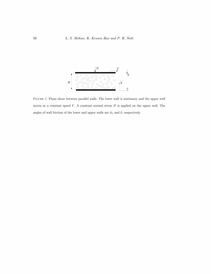
Consider steady, fully developed flow between horizontal walls which are separated by
a gap H (see figure 1). The upper wall moves in the positive x direction with a constant
speed V , the lower wall is stationary, and a constant compressive normal stress N is
applied to the upper wall. (For the case of zero gravity, considered in section 5.1, the
bottom wall is also subjected to a compressive normal stress of magnitude N .) Typically
in an experiment, the initial gap, before the walls are set in motion, is fixed, at say H0.
Owing to dilation and compaction during shearing, this can change to a different value
H once steady flow is established.
The velocity fields are of the form
vx = vx(y) , vy = 0 , vz = 0 ,
ωx = 0 , ωy = 0 , ωz = ωz(y) ,
(3.1)
and all the stresses are assumed to depend only on the y− coordinate. Equations (3.1)
and (2.1) imply that Dρ/Dt = 0. Hence the material is at a critical state, and the yield
condition is given by (2.5).
The mass balance (2.1) is identically satisfied, and the x− and y− components of the
linear momentum balance (2.2) reduce to
dσyx
dy= 0 ,
dσyy
dy= −ρ g. (3.2a,b)
Page 12
12 L. S. Mohan, K. Kesava Rao and P. R. Nott
As there is no externally imposed body couple, the z− component of the angular mo-
mentum balance reduces to
dMyz
dy+ σxy − σyx = 0. (3.3)
The diagonal components of Eij are zero, and hence the flow rule (2.9) implies that
0 =λ
6τ(2σ′
xx − σ′
yy − σ′
zz), (3.4a)
0 =λ
6τ(2σ′
yy − σ′
xx − σ′
zz), (3.4b)
0 =λ
6τ(2σ′
zz − σ′
xx − σ′
yy). (3.4c)
As σ′
ij = σij − σδij , we have σ′
xx + σ′
yy + σ′
zz = 0. Hence, (3.4) imply equality of the
normal stresses,
σxx = σyy = σzz = σ = σc(ν). (3.5)
¿From (3.1) and (2.9), we have
Exz = Ezx = Eyz = Ezy = 0,
which imply that all the shear stresses except σxy and σyx vanish. Similarly, all the couple
stresses except Myz vanish. Hence the yield condition (2.4a) reduces to
τ2 = a1(σ2xy + σ2
yx) + 2a2σxyσyx +M2
yz
(Ldp)2 = (σc sinφ)2. (3.6)
The remaining equations of the flow rule (2.9) are
Exy =dvx
dy+ ωz =
λ
τ(a1σyx + a2σxy) , (3.7)
Eyx = −ωz =λ
τ(a1σxy + a2σyx) , (3.8)
Hzy =dωz
dy=λ
τ
Myz
(Ldp)2 . (3.9)
Page 13
Frictional Cosserat model for slow granular flows 13
Eliminating λ from (3.7) - (3.9), we get
dvx
dy= − (A+ 1)(σxy + σyx)ωz
σxy +Aσyx, (3.10)
dωz
dy= − ωz
(Ldp)2
2(A+ 1)m
(σxy +Aσyx). (3.11)
Equations (3.2), (3.3), (3.6), and (3.10) – (3.11) constitute the governing equations for
plane shear. They may be cast in dimensionless form by introducing the dimensionless
variables
ξ =yH , u = vx
V , σij =σij
N ,
m = 1L√
2(A+ 1)
Myz
(Ndp), and ω = ωz H
V .
(3.12)
The governing equations now take the form
dσyx
dξ= 0, (3.13)
dσyy
dξ+Bν = 0, (3.14)
ε αdm
dξ+
1
2(A+ 1)(σxy − σyx) = 0, (3.15)
(σ2xy + σ2
yx) + 2Aσxyσyx + 4(A+ 1)2m2 − 2(A+ 1)(σc sinφ)2 = 0, (3.16)
du
dξ+
(A+ 1)(σxy + σyx)ω
σxy +Aσyx= 0, (3.17)
εαdω
dξ+
2(A+ 1)mω
(σxy +Aσyx)= 0. (3.18)
where ε ≡ dp/H , B ≡ ρpgH/N is ratio of the gravitational head at the base to the
applied normal stress on the top plate, and α ≡ L/√
2(A+ 1).
The yield condition (3.16) may be solved for σxy to get
σxy = −Aσyx+√
(A2 − 1)σ2yx + 2(A+ 1)σ2
csin2φ− 4(A+ 1)2m2 (3.19)
where σc = σc/N .
Page 14
14 L. S. Mohan, K. Kesava Rao and P. R. Nott
4. Boundary Conditions
Equations (3.13) - (3.19) require five boundary conditions. We first consider boundary
conditions for the linear and angular momentum balances (3.13)-(3.15). The first is the
specification of the normal stress N acting on the upper wall, i.e.
σyy(1) = 1. (4.1)
If the material slips relative to a wall, we use the usual friction boundary condition
(Brennen & Pearce 1978, Nedderman 1992, p. 41),
−σyx/σyy = tan δ, (4.2)
where δ, the angle of wall friction, is a property of the wall and the granular material. This
is an approximate time-averaged boundary condition and is not expected to capture rapid
events such as stick-slip. For the special case of shear in the absence of gravity between
identical walls, (4.2) applies on both walls, which is equivalent to specifying (4.2) at one
wall and m(ξ = 1/2) = 0, as elaborated in §5.1. We therefore have the requisite number
of boundary conditions for (3.13)-(3.15).
As discussed in Kaza (1982)and Nedderman (1992, p. 161), the classical frictional
model suggests that tan δ ≤ sinφ. A “fully rough” wall is defined as one for which the
angle of wall friction satisfies
tan δ = sinφ. (4.3)
Physically we may try to realize this by coating the wall with a monolayer of the granular
material. In some experiments involving walls coated with sand, polystyrene beads, and
glass beads, the measured values of δ were found to be within 1◦ of the values predicted
by (4.3) (Kaza 1982). However, (4.3) should not be taken too seriously, as it rests on
assumptions which are difficult to verify. Moreover, it is well known that grains do not
Page 15
Frictional Cosserat model for slow granular flows 15
pack as densely near a solid boundary as in the bulk; hence it is reasonable to suppose
that a fully rough wall is an idealization that is difficult to achieve practically.
When the material does not slip relative to a wall, (as is the case in most of the
problems considered in §5), friction is not fully mobilized and an alternative to (4.2)
must be specified. One choice is to specify the value of m (= mw) at the wall. In this
work, we use the condition
σxy = σyx (4.4)
at a wall where the material does not slip relative to it. This is equivalent to specifying
mw, as it can then be expressed in terms of σyx using (4.4) and the yield condition (3.16).
Equation (4.4) was motivated by an expectation that Cosserat effects such as the stress
asymmetry would vanish outside the shear layer. However, the results presented later do
not support this conjecture. Fortunately, the velocity profile is relatively insensitive to
the value of mw, as discussed in section 5.
We now consider boundary conditions for the flow rule (3.17)-(3.18). If the material
slips relative to a boundary, we assume as in our earlier work (Mohan et al. 1999) that
v − vw = −Kdp n×ω, (4.5)
where K is a dimensionless constant which reflects the roughness of the wall, n is the
unit normal at the wall (pointing into the granular material) and vw is the linear velocity
of the wall. This boundary condition relates the angular velocity of the material adjacent
to the wall to the slip velocity. It was introduced by Tejchman & Gudehus (1993) and
Tejchman & Wu (1993), who formulated it in terms of displacement and rotation. Here
we use an equivalent form in terms of velocity and angular velocity.
An explanation of this condition was provided by Mohan et al. (1999), which we repeat
here for the sake of completeness. If we consider a single spherical particle moving past
Page 16
16 L. S. Mohan, K. Kesava Rao and P. R. Nott
a stationary wall, the linear velocity v′ of its center of mass and the angular velocity ω′
about an axis passing through the center of mass are related by v′ = (dp/2)n×ω′ if the
particle rolls without slipping. Conversely, if the particle slides without rolling, ω′ = 0
but v′ is arbitrary. For the boundary condition (4.5), these limits correspond to K → 1/2
and K → ∞, respectively. If the particles are rough or angular, rolling and slipping may
be altogether absent, reducing the lower limit of K to zero. In a continuum description,
we expect that K will decrease as the wall roughness increases. It is reasonable to expect
thatK and the angle of wall friction δ are related, as they both characterize the roughness
of the wall. However, as data bearing on this is lacking, both K and δ will be treated as
independent parameters.
For the present problem, (4.5) may be written in dimensionless form as
u(1) = 1 + εKω(1) (4.6)
if (4.2) holds at the upper wall, and
u(0) = −εKω(0) (4.7)
if (4.2) holds at the lower wall.
If the material does not slip relative to the upper wall, we have
u(1) = 1. (4.8)
Similarly, if the material does not slip relative to the lower wall, we have
u(0) = 0 (4.9)
Page 17
Frictional Cosserat model for slow granular flows 17
5. Results for plane shear
We first consider the case of zero gravity, for which the parameter B in (3.14) is set to
zero. We then consider finite gravity, for which B determines the gravitational overburden
at the base in comparison with the applied normal load.
5.1. Shear in the absence of gravity
We first consider the case where the two walls are identical, i.e. δL = δ, where δL and
δ are the angles of wall friction of the lower and upper walls, respectively. The domain
is symmetric about the mid-plane ξ = 1/2, and (3.13)-(3.18) admit a solution wherein
the stresses are symmetric and m is antisymmetric about ξ = 1/2. Similarly u − 1/2 is
antisymmetric while the angular velocity ω is symmetric about ξ = 1/2. It then suffices
to solve the problem in the half-domain 1/2 ≤ ξ ≤ 1, with boundary conditions
m(1/2) = 0, u(1/2) = 1/2. (5.1)
and (4.1), (4.2)( at ξ = 1), and (4.6). The momentum balances (3.13) and (3.14) and the
boundary conditions (4.1) and (4.2) imply that
σyy = 1 and σyx = − tan δ. (5.2)
Hence (3.5) implies that the solids fraction ν is also a constant, and its value is given by
σc(ν) = 1. Substituting for σxy from (3.19) into the angular momentum balance (3.15)
yields the following equation for the couple stress:
α εdm
dξ= −a∓
√
b2 −m2 (5.3)
where
a =tan δ
2and b = (a2 +
1
2(A+ 1)(sin2 φ− tan2 δ))1/2. (5.4)
This must be solved for m in the region 1/2 ≤ ξ ≤ 1 with boundary condition (5.1). The
shear stress σxy then follows from (3.19).
Page 18
18 L. S. Mohan, K. Kesava Rao and P. R. Nott
Let us consider the choice of signs in the right-hand side of (5.3). If the negative sign
is used in front of the square root, dm/dξ < 0. Equation (5.1) implies that |m| increases
as ξ increases from 1/2. Therefore, for small enough values of ε, m = −b at some value
of ξ = ξr < 1, and hence a real valued solution cannot be constructed for ξ > ξr. We
therefore choose the positive sign in front of the square root. This leads to an acceptable
solution because, though dm/ξ ≥ 0, the structure of (5.3) ensures that |m| ≤√b2 − a2.
This choice of roots is used throughout the paper. It corresponds to the use of the negative
sign in front of the square root in (3.19).
The differential equation (5.3) may be integrated by making the substitution m =
b sinψ, to get
ξ − 1/2
α ε= ψ +
a√b2 − a2
ln
(
c+ tan(ψ/2)
c− tan(ψ/2)
)
(5.5)
with c =√b− a/
√b+ a. The velocity fields must be determined by integrating (3.17)
and (3.18) numerically subject to the boundary conditions (4.6) and the second of (5.1).
Before discussing results for arbitrary values of the angle of wall friction δ, it is in-
structive to consider the special case of a fully rough wall, defined by (4.3), for which
b = a. In this case, (5.3) and the first of (5.1) imply that m and all its derivatives with
respect to ξ vanish at ξ = 1/2, resulting in m(ξ) = 0. It then follows that
σxy = σyx = − tan δ, (5.6a)
ω = ω1 (constant), and (5.6b)
u = 1/2− 2ω1(ξ − 1/2). (5.6c)
Using the boundary condition (4.6), we get
ω1 = −1/(2 + 2εK). (5.6d)
As expected from the direction of motion of the upper plate (figure 1), ω1 is negative,
Page 19
Frictional Cosserat model for slow granular flows 19
implying that the particles rotate about the z− axis in the clockwise direction. If the gap
width is large compared to the particle diameter, ε → 0 and therefore u(1) → 1. Thus
the velocity slip at the walls vanishes when thick layers are sheared.
Thus the couple stress vanishes, the stress tensor is symmetric, and the angular velocity
equal to half the vorticity, all of which are features of a classical continuum. However, the
classical frictional model does not lead to a unique velocity profile, unlike the Cosserat
model. As noted earlier, this is because the two models are not identical for this special
case.
For tan δ < sinφ, rather than determining m by solving (5.5) and then the velocity
fields by integrating (3.17)-(3.18), all the fields are obtained by integrating (3.15) - (3.18),
after substituting for σxy from (3.19). This is done because such a numerical solution
procedure is anyway required for plane shear under gravity and cylindrical Couette flow,
as analytical solutions could not be constructed for these problems. The system of equa-
tions were solved numerically using the lsoda routine (Petzold 1983) from the odepack
library in netlib. Our numerical procedure was verified by favourable comparison with
the analytical solution given by (5.5), and the asymptotic solutions in §A (see figures 4
and 7).
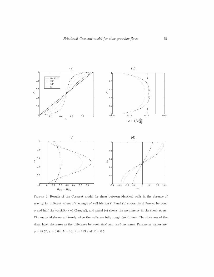
Figure 2 shows the velocity and stress profiles for different values of the angle of wall
friction δ. The velocity profile is linear for the case of fully rough walls (tan δ = sinφ),
and becomes curved as the difference between sinφ and tan δ increases. Correspondingly,
the thickness of the shearing layer decreases. Panels (b) and (c) illustrate the deviation
of ω from half the vorticity and the stress asymmetry, respectively. The choice of signs
in (3.19) forces σyx − σxy to be non-negative.
When the angle of friction of the lower wall (δL) differs from that of the upper wall (δ),
the solution is no longer symmetric about ξ = 1/2. We assume without loss of generality
Page 20
20 L. S. Mohan, K. Kesava Rao and P. R. Nott
that δL > δ. If the friction boundary condition (4.2) is satisfied at the upper wall,
−σyx/σyy = tan δ < tan δL. Hence (4.2) is not satisfied at the lower wall. Conversely, if
(4.2) is satisfied at the lower wall, −σyx/σyy = tan δL > tan δ at the upper wall. As this
is not permissible within the present framework, (4.2) is used at the upper wall, along
with the velocity boundary condition (4.6). At the lower wall we use boundary condition
(4.4) for the couple stress, and the no-slip condition (4.9).
Equations (3.15) and (4.4) imply that dm/dξ = 0 at ξ = 0. It then follows from (5.3)
that all higher derivatives of m vanish at ξ = 0. Hence, the couple stress is constant and
the shear stresses are equal,
m = m0 = (b2 − a2)1/2, (5.7a)
σxy = σyx = − tan δ. (5.7b)
Substitution of these in (3.17) yields
du
dξ= −2ω.
Thus, the stress tensor is symmetric and the angular velocity is equal to half the vorticity,
as in a classical continuum. However, the couple stress is finite and the velocity field is
uniquely determined, in contrast to the predictions of a classical frictional model. The
velocity fields are readily obtained by integrating (3.17)-(3.18), resulting in
ω = ω1 exp(−k(1 − ξ)/ε), (5.8a)
u =−2ω1ε
k(exp(−k(1 − ξ)/ε) − exp(−k/ε)), (5.8b)
where
ω1 = − ε−1(2/k +K − 2e−k/ε/k)−1 (5.8c)
Page 21
Frictional Cosserat model for slow granular flows 21
is the angular velocity at the upper wall and
k = m0/(α a). (5.8d)
We see from equation (5.8b) that the shear layer thickness increases with the roughness
of the upper wall. The velocity profile becomes progressively linear as tan δ → sinφ (or
k → 0). However, the velocity profile in this limit still differs from the uniformly shearing
solution given in (5.6c), owing to the difference in velocity boundary conditions at the
lower wall in the two cases. Profiles of the velocity and angular velocity (which equals half
the vorticity) fields are shown in figure 3 for three values of δ. The increasing localization
of shear near the upper wall as δ decreases is apparent. In this case, the velocity slip
at the upper wall is nonzero in the limit ε → 0. This is in contrast to the case of shear
between fully rough walls, where the velocity slip vanishes in this limit.
When the Couette gap is large compared to the grain size, i.e. ε≪ 1, an approximate
solution may be obtained by an asymptotic analysis, described in Appendix §A. For shear
between identical walls, the couple stress is constant and the Cauchy stress is symmetric,
i.e.
m = m0 = (b2 − a2)1/2, σxy = σyx = − tan δ, (5.9a,b)
except in a boundary layer of thickness ∼ O(ε) near ξ = 1/2. In the boundary layer, m
decreases from m0 to zero at ξ = 1/2, but this variation has no effect on the velocity
fields (see §A.0.1). There is no boundary layer when one of the walls is rougher. The
leading order velocity fields for the two cases, given in (A 3) and (A 4), may be combined
and written as,
ω =−(1 − u0)
ε(K + 2/k)exp (−k(1 − ξ)/ε) , (5.9c)
u− u0 =(1 − u0)2/k
(K + 2/k)exp (−k(1 − ξ)/ε) . (5.9d)
Here u0 is the reference velocity, equal to 1/2 (the velocity at the symmetry axis) for
Page 22
22 L. S. Mohan, K. Kesava Rao and P. R. Nott
shear between identical walls, and zero (the velocity of the lower wall) for a rougher
lower wall. The rapid decay of ω and u with distance from the wall is apparent. Equation
(5.9) is not valid when the walls are fully rough, as we have assumed in its derivation
that k ≫ ε (see §A.0.1); as stated earlier, all Cosserat effects vanish and the material
shears uniformly in the gap when the walls are fully rough. The asymptotic solution
for the velocity fields (5.9c-d) agrees well with the numerical solution for shear between
identical walls and for the case of a rougher lower wall (figure 4). The dependence of the
shear layer thickness on ε is discussed in §8.
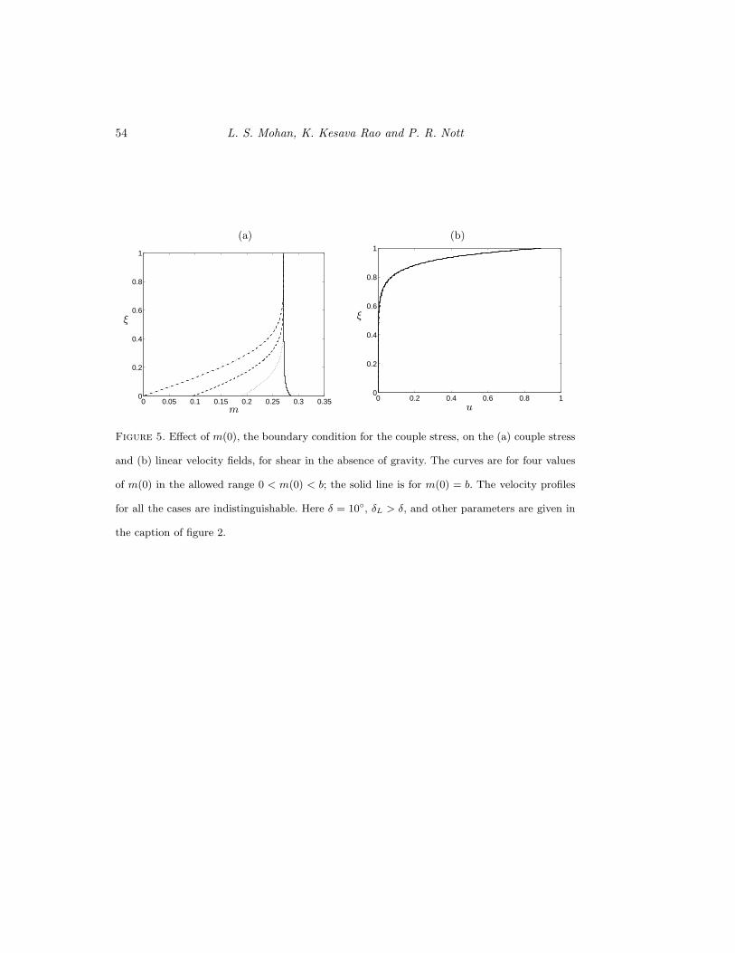
As discussed in §4, we do not have rigourous basis for the boundary condition (4.4) for
the case of a rougher lower wall. A study of the sensitivity of the model predictions to
varying the boundary condition is therefore in order. The imposition of any condition for
the angular momentum at the lower wall is equivalent to specifying the value of the couple
stress there. In particular, the boundary condition (4.4) is equivalent to m(0) = m0,
where m0 is defined by (5.7a). For the shear stress σxy to be real, (5.3) implies that
the maximum value m(0) can take is b, defined in (5.4); for ω and the velocity gradient
to increase in magnitude with distance from the lower wall (as is physically reasonable)
the flow rule (3.17)-(3.18) dictates that the minimum value m(0) can take is zero. As
shown in figure 5, the value of m(0) has a negligible effect on the velocity profile. The
reason for this result is that the couple stress approaches a common asymptote as ξ → 1
for all values of m(0) (see also §A.0.2). As the velocity and angular velocity fields decay
exponentially with distance from the upper wall, with a decay length set by the couple
stress near the upper wall, the boundary condition for m(0) is largely unimportant in
determining the velocity fields.
Page 23
Frictional Cosserat model for slow granular flows 23
5.2. Shear in a gravitational field
Let us first consider the case where both walls have the same roughness, so that δL = δ.
Equations (3.13) and (3.14) imply
σyx = constant,dσyy
dξ= −B ν. (5.10)
Hence the ratio |σyx|/σyy decreases with distance from the upper wall, and (4.2) cannot
be satisfied at the lower wall if it holds at the upper wall. Therefore, for the same reasons
given in §5.1 (for the case δ < δL), the boundary conditions are (4.1), (4.2) and (4.6) at
the upper wall (ξ = 1), and (4.4) and (4.9) at the lower wall (ξ = 0).
As the normal stress σyy increases with distance from the upper wall, (3.5) implies
that the solids fraction ν also increases. However, in the regime of high solids fraction,
a moderate change in σc causes only a small change in ν. As gravitational compaction
alone is usually sufficient to bring the solids fraction to a level close to maximum packing,
we treat the material as incompressible, and the mean stress at critical state σc as an
independent field. This approximation is used only to simplify the analysis; the variation
in the body force can be easily be accounted for.
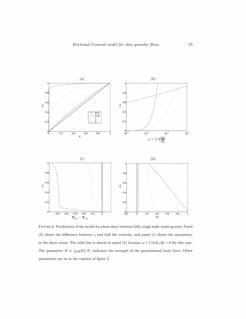
Figure 6 shows results for shear between fully rough walls under gravity, for four values
of the parameter B. The solution for B = 0 corresponds to the uniform shear solution in
the absence of gravity. As B increases, the velocity profile becomes curved, and shear is
localized in a thin layer adjacent to the upper wall for large B. While the couple stress
increases with distance from the upper wall, other Cosserat effects, such as the difference
between ω and half the vorticity and the asymmetry in the Cauchy stress are maximum
at the upper wall.
For large Couette gap, the asymptotic analysis in §A.0.2 provides an approximate
solution. If the walls are not fully rough, the leading order solution for the velocity fields
Page 24
24 L. S. Mohan, K. Kesava Rao and P. R. Nott
is identical to that for gravity-free shear, given by (5.9) with u0 = 0. If the walls are fully
rough, there is a boundary layer of thickness ∼ ε2/3 near the upper wall within which
m deviates from m0. Consequently, the shear layer is thinner than in the zero gravity
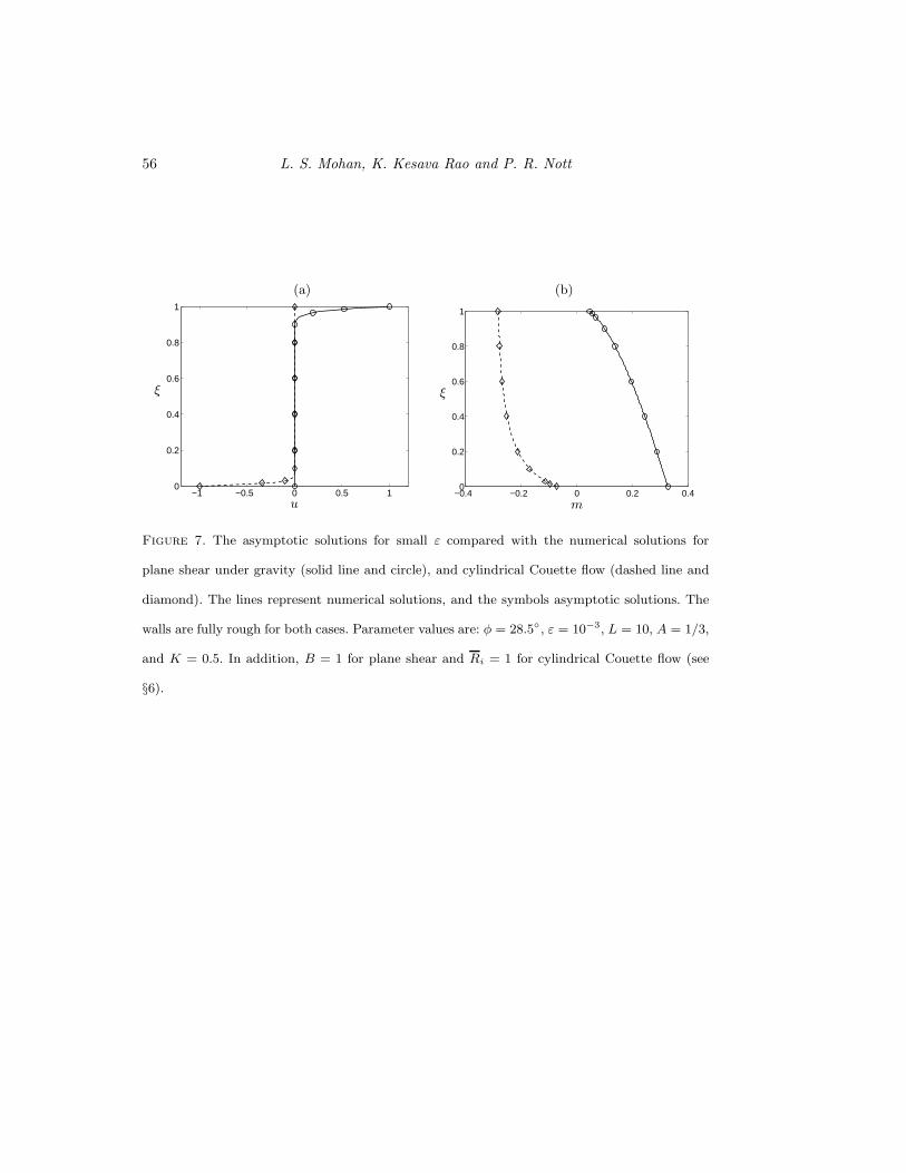
case(see §8). The leading order asymptotic solution for the couple stress and velocity
fields are compared with the numerical solution in figure 7, showing good agreement. As
a small value of ε has been used, the slip velocity at the upper wall is negligible.
If δL is sufficiently smaller than δ, the friction boundary condition (4.2) can be satisfied
at the lower wall. Assuming that the density of the material remains constant across the
layer (see above), it is seen that (4.2) holds at the lower wall if tan δL ≤ tan δ/(1 +Bν),
and at the upper wall if tan δL ≥ tan δ/(1+Bν). The shear layer is adjacent to the lower
wall in the former case, and adjacent to the upper wall (as in figure 6.
6. Cylindrical Couette flow
The cylindrical Couette cell is a common device for making rheological measurements.
The material is confined between two vertical coaxial cylinders of radii Ri and Ri +H .
Typically, the inner cylinder is rotated at constant speed, while the outer cylinder is kept
stationary.
Using the cylindrical coordinates indicated in figure 8, the velocity field for steady
axisymmetric flow is assumed to be of the form
vr = 0, vz = 0, vθ = vθ(r). (6.1)
The only non-vanishing component of the vorticity is in the z- direction, and we expect
the same for the intrinsic angular velocity,
ωr = ωθ = 0, ωz = ωz(r). (6.2)
As in the case of plane shear (see §3), the diagonal components of (2.8) imply equality
Page 25
Frictional Cosserat model for slow granular flows 25
of normal stresses,
σrr = σθθ = σzz = σc(ν) (6.3)
It also follows from the flow rule (2.8) that all shear stresses except σrθ and σθr vanish,
and all couple stresses except Mrz vanish.
We note as an interesting aside that, as σrz = 0, there is no shear stress in the vertical
direction on the walls of the Couette cell, regardless of either the wall roughness or the
height of the material in the cell. In contrast, it is well known that the shear stress at
the walls supports a part of the weight of a static granular column, leading to the so-
called Janssen saturation of the stress with distance from the upper surface (Janssen
1895; Nedderman 1992, p. 84). While clear evidence as to whether or not this feature is
preserved during flow is lacking, the data of Tardos et al. (1998) appear to be inconsistent
with the Janssen solution. Nevertheless, measurements of σrz in cylindrical Couette flow
have not been reported in the literature, and such measurements would provide a valuable
check on the model predictions.
We introduce the dimensionless variables
u = vθVi, ω = ωzH
Vi, ξ = r −Ri
H , ζ = zH ,
σij =σij
ρp g H, σc = σc
ρp gH, m = 1
L√
2(A+ 1)
Mrzρp gHdp
,
(6.4)
where Ri and Vi are the radius and the velocity of the inner cylinder, respectively. The
yield condition (2.4a) then reduces to
(σ2rθ + σ2
θr) + 2Aσθrσrθ + 4(A+ 1)2m2 = 2(A+ 1)(σc sinφ)2. (6.5)
As in §3, the remaining components of the flow rule, after elimination of the factor
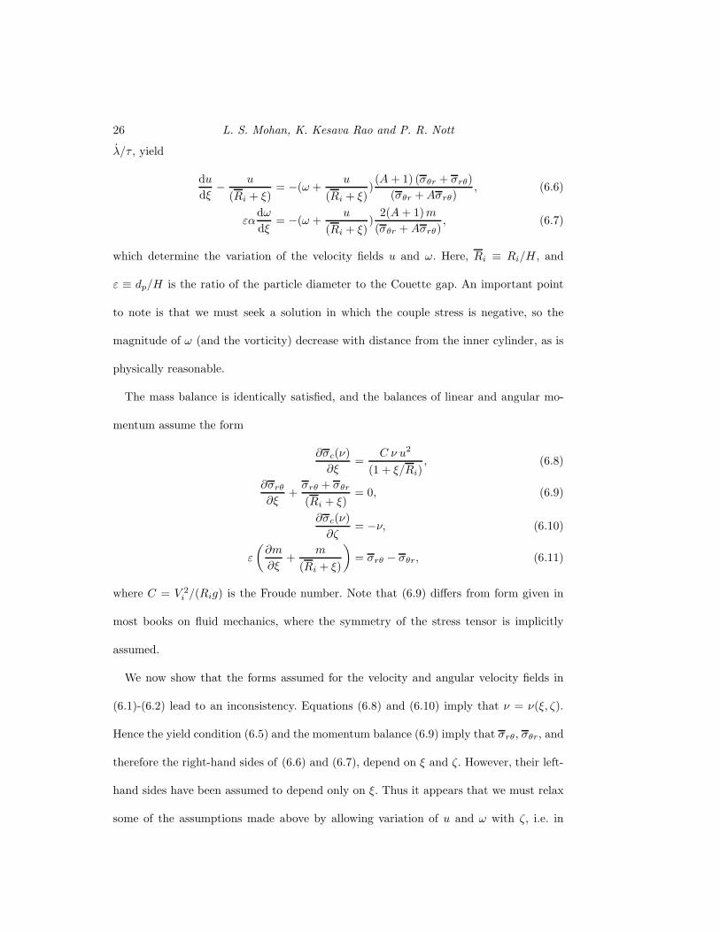
Page 26
26 L. S. Mohan, K. Kesava Rao and P. R. Nott
λ/τ , yield
du
dξ− u
(Ri + ξ)= −(ω +
u
(Ri + ξ))(A+ 1) (σθr + σrθ)
(σθr +Aσrθ), (6.6)
εαdω
dξ= −(ω +
u
(Ri + ξ))
2(A+ 1)m
(σθr +Aσrθ), (6.7)
which determine the variation of the velocity fields u and ω. Here, Ri ≡ Ri/H , and
ε ≡ dp/H is the ratio of the particle diameter to the Couette gap. An important point
to note is that we must seek a solution in which the couple stress is negative, so the
magnitude of ω (and the vorticity) decrease with distance from the inner cylinder, as is
physically reasonable.
The mass balance is identically satisfied, and the balances of linear and angular mo-
mentum assume the form
∂σc(ν)
∂ξ=
C ν u2
(1 + ξ/Ri), (6.8)
∂σrθ
∂ξ+σrθ + σθr
(Ri + ξ)= 0, (6.9)
∂σc(ν)
∂ζ= −ν, (6.10)
ε
(
∂m
∂ξ+
m
(Ri + ξ)
)
= σrθ − σθr, (6.11)
where C = V 2i /(Rig) is the Froude number. Note that (6.9) differs from form given in
most books on fluid mechanics, where the symmetry of the stress tensor is implicitly
assumed.
We now show that the forms assumed for the velocity and angular velocity fields in
(6.1)-(6.2) lead to an inconsistency. Equations (6.8) and (6.10) imply that ν = ν(ξ, ζ).
Hence the yield condition (6.5) and the momentum balance (6.9) imply that σrθ, σθr, and
therefore the right-hand sides of (6.6) and (6.7), depend on ξ and ζ. However, their left-
hand sides have been assumed to depend only on ξ. Thus it appears that we must relax
some of the assumptions made above by allowing variation of u and ω with ζ, i.e. in
Page 27
Frictional Cosserat model for slow granular flows 27
the vertical direction, and also to allow a non-zero ωr. This however leads to a large
set of coupled partial differential equations whose solution appears to be a formidable
task. This is contrary to our purpose of developing simple solutions that bring out the
qualitative features of our model. However, it is possible construct a simple approximate
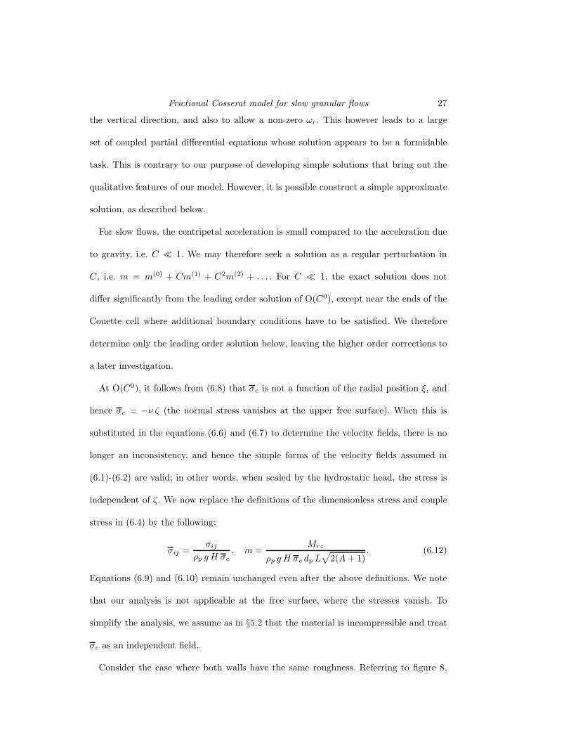
solution, as described below.
For slow flows, the centripetal acceleration is small compared to the acceleration due
to gravity, i.e. C ≪ 1. We may therefore seek a solution as a regular perturbation in
C, i.e. m = m(0) + Cm(1) + C2m(2) + . . . . For C ≪ 1, the exact solution does not
differ significantly from the leading order solution of O(C0), except near the ends of the
Couette cell where additional boundary conditions have to be satisfied. We therefore
determine only the leading order solution below, leaving the higher order corrections to
a later investigation.
At O(C0), it follows from (6.8) that σc is not a function of the radial position ξ, and
hence σc = −ν ζ (the normal stress vanishes at the upper free surface). When this is
substituted in the equations (6.6) and (6.7) to determine the velocity fields, there is no
longer an inconsistency, and hence the simple forms of the velocity fields assumed in
(6.1)-(6.2) are valid; in other words, when scaled by the hydrostatic head, the stress is
independent of ζ. We now replace the definitions of the dimensionless stress and couple
stress in (6.4) by the following:
σij =σij
ρp g H σc, m =
Mrz
ρp g H σc dp L√
2(A+ 1). (6.12)
Equations (6.9) and (6.10) remain unchanged even after the above definitions. We note
that our analysis is not applicable at the free surface, where the stresses vanish. To
simplify the analysis, we assume as in §5.2 that the material is incompressible and treat
σc as an independent field.
Consider the case where both walls have the same roughness. Referring to figure 8,
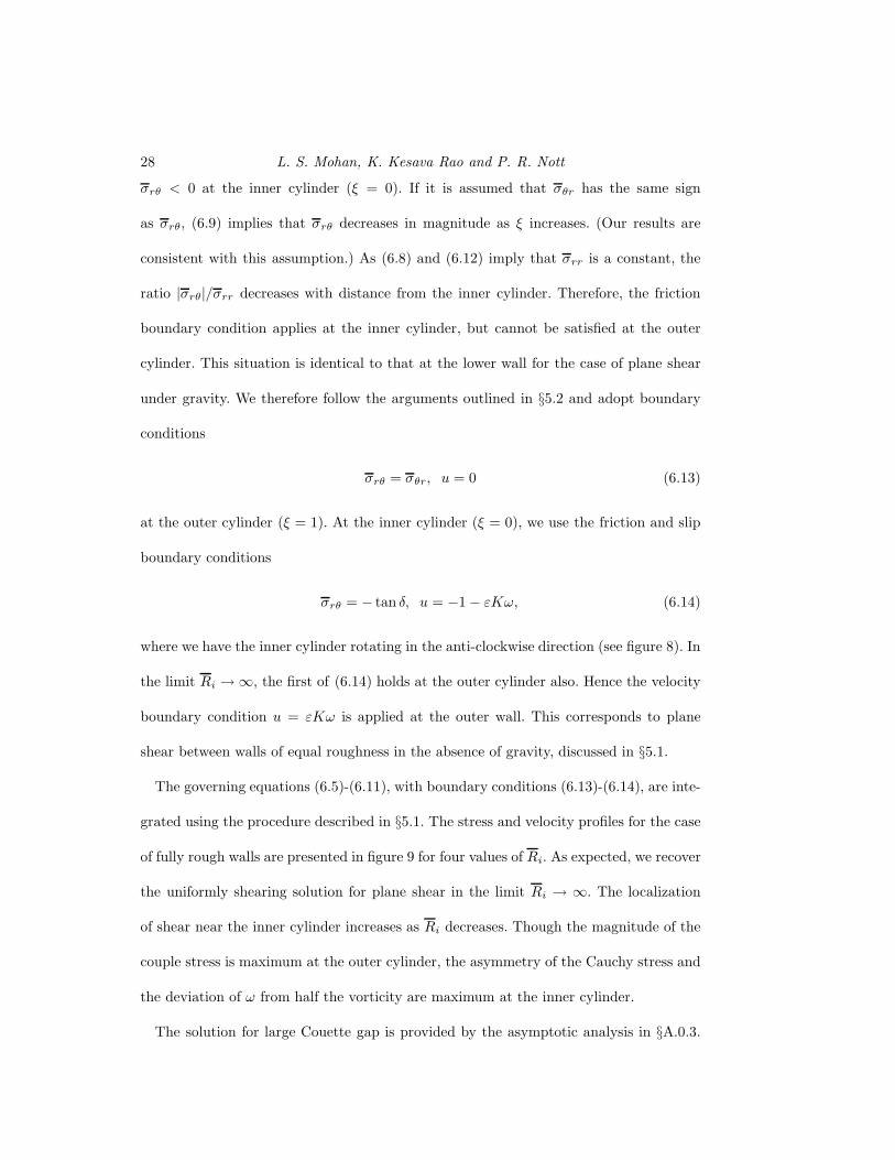
Page 28
28 L. S. Mohan, K. Kesava Rao and P. R. Nott
σrθ < 0 at the inner cylinder (ξ = 0). If it is assumed that σθr has the same sign
as σrθ, (6.9) implies that σrθ decreases in magnitude as ξ increases. (Our results are
consistent with this assumption.) As (6.8) and (6.12) imply that σrr is a constant, the
ratio |σrθ|/σrr decreases with distance from the inner cylinder. Therefore, the friction
boundary condition applies at the inner cylinder, but cannot be satisfied at the outer
cylinder. This situation is identical to that at the lower wall for the case of plane shear
under gravity. We therefore follow the arguments outlined in §5.2 and adopt boundary
conditions
σrθ = σθr, u = 0 (6.13)
at the outer cylinder (ξ = 1). At the inner cylinder (ξ = 0), we use the friction and slip
boundary conditions
σrθ = − tan δ, u = −1 − εKω, (6.14)
where we have the inner cylinder rotating in the anti-clockwise direction (see figure 8). In
the limit Ri → ∞, the first of (6.14) holds at the outer cylinder also. Hence the velocity
boundary condition u = εKω is applied at the outer wall. This corresponds to plane
shear between walls of equal roughness in the absence of gravity, discussed in §5.1.
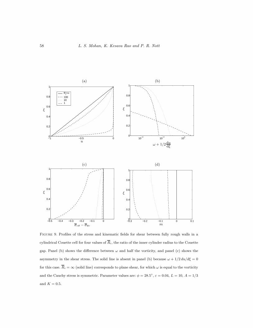
The governing equations (6.5)-(6.11), with boundary conditions (6.13)-(6.14), are inte-
grated using the procedure described in §5.1. The stress and velocity profiles for the case
of fully rough walls are presented in figure 9 for four values of Ri. As expected, we recover
the uniformly shearing solution for plane shear in the limit Ri → ∞. The localization
of shear near the inner cylinder increases as Ri decreases. Though the magnitude of the
couple stress is maximum at the outer cylinder, the asymmetry of the Cauchy stress and
the deviation of ω from half the vorticity are maximum at the inner cylinder.
The solution for large Couette gap is provided by the asymptotic analysis in §A.0.3.
Page 29
Frictional Cosserat model for slow granular flows 29
The leading order solution is the same as in plane shear (with or without gravity) when
the walls are not fully rough. If the walls are fully rough, the solution is similar in form to
that for plane shear under gravity: the couple stress rises to m0 within a boundary layer
of thickness ∼ ε2/3 near the inner cylinder, and remains at m0 outside the boundary
layer. The velocity fields are determined by the couple stress within the boundary layer,
and are independent of the wall roughness. The leading order asymptotic solution for the
velocity fields is compared with the numerical solution for fully rough walls in figure 7.
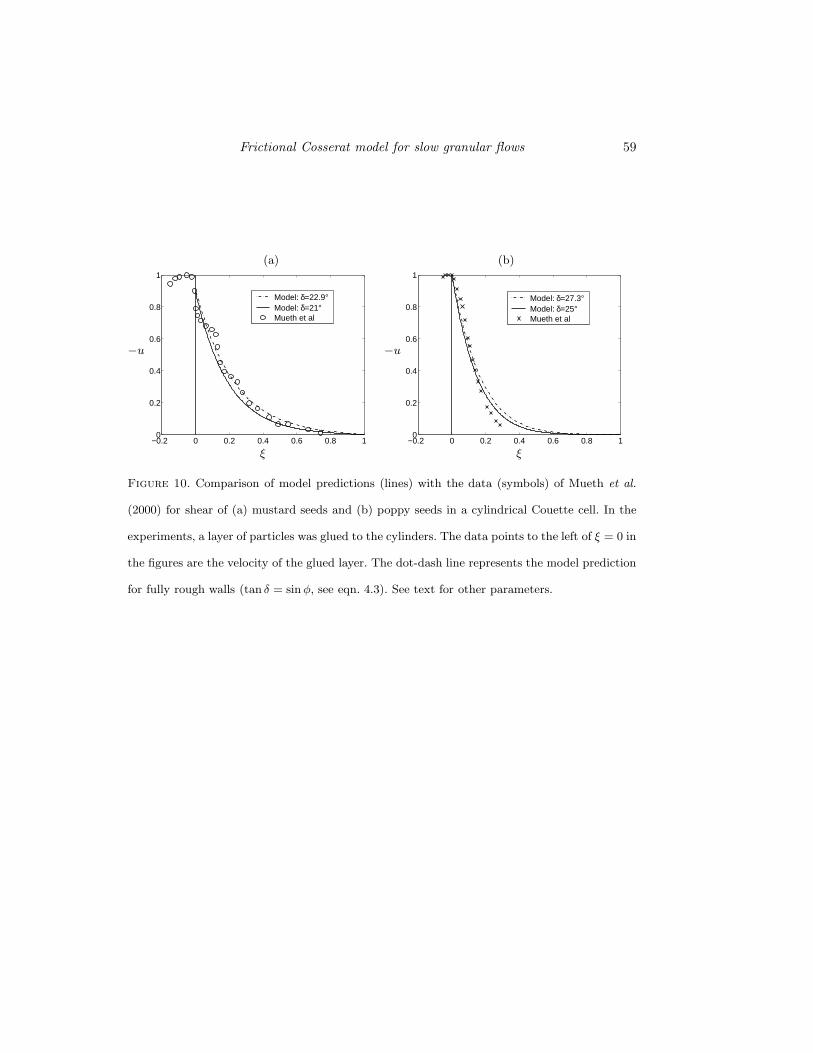
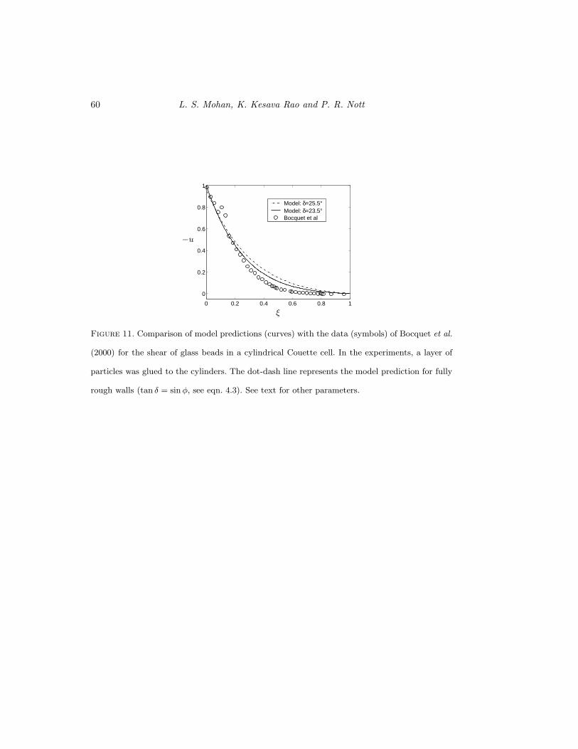
6.1. Comparison with experimental data
Experimental measurements of the velocity profile in cylindrical Couette flow of granular
materials have recently been reported by Mueth et al. (2000) and Bocquet et al. (2000).
Mueth et al. (2000) used mustard and poppy seeds and obtained the velocity profiles using
magnetic resonance imaging. Bocquet et al. (2000) used glass beads and measured the
velocity profile by video imaging of the upper surface of the granular column; they also
applied upward aeration across the granular column, and observed that it has negligible
effect on the velocity profile. From the data reported in their papers, we have determined
the parameter R, defined in §1, to be in the range 6×10⁻⁹− 10−3 for the experiments of
Mueth et al. (2000), and 7×10⁻⁹− 2×10⁻⁴ for that of Bocquet et al. (2000). The Froude
number C, defined below (6.11), for the two studies was in the range 10−6 − 6 × 10⁻²
and 2× 10⁻⁶ − 2× 10⁻², respectively. As R and C are both small for these studies, it is
appropriate to compare our model predictions with their data. Both find that the shape
of the velocity profile is independent of the rotation rate of the inner cylinder, which, of
course, is also a feature of our model.
The predictions of the velocity profile using our Cosserat model are compared with
the data of Mueth et al. (2000) in figure 10 and with the data of Bocquet et al. (2000)
in figure 11. In both studies, the inner and outer cylinders were coated with a layer of
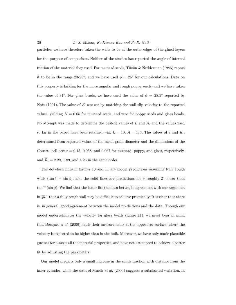
Page 30
30 L. S. Mohan, K. Kesava Rao and P. R. Nott
particles; we have therefore taken the walls to be at the outer edges of the glued layers
for the purpose of comparison. Neither of the studies has reported the angle of internal
friction of the material they used. For mustard seeds, Tuzun & Nedderman (1985) report
it to be in the range 23-25◦, and we have used φ = 25◦ for our calculations. Data on
this property is lacking for the more angular and rough poppy seeds, and we have taken
the value of 31◦. For glass beads, we have used the value of φ = 28.5◦ reported by
Nott (1991). The value of K was set by matching the wall slip velocity to the reported
values, yielding K = 0.65 for mustard seeds, and zero for poppy seeds and glass beads.
No attempt was made to determine the best-fit values of L and A, and the values used
so far in the paper have been retained, viz. L = 10, A = 1/3. The values of ε and Ri,
determined from reported values of the mean grain diameter and the dimensions of the
Couette cell are: ε = 0.15, 0.058, and 0.067 for mustard, poppy, and glass, respectively,
and Ri = 2.29, 1.89, and 4.25 in the same order.
The dot-dash lines in figures 10 and 11 are model predictions assuming fully rough
walls (tan δ = sinφ), and the solid lines are predictions for δ roughly 2◦ lower than
tan−1(sinφ). We find that the latter fits the data better, in agreement with our argument
in §5.1 that a fully rough wall may be difficult to achieve practically. It is clear that there
is, in general, good agreement between the model predictions and the data. Though our
model underestimates the velocity for glass beads (figure 11), we must bear in mind
that Bocquet et al. (2000) made their measurements at the upper free surface, where the
velocity is expected to be higher than in the bulk. Moreover, we have only made plausible
guesses for almost all the material properties, and have not attempted to achieve a better
fit by adjusting the parameters.
Our model predicts only a small increase in the solids fraction with distance from the
inner cylinder, while the data of Mueth et al. (2000) suggests a substantial variation. In
Page 31
Frictional Cosserat model for slow granular flows 31
spite of this difference, the predicted velocity profiles are in good agreement with their
data. Thus it appears that the velocity field is relatively insensitive to the dilation of the
granular medium.
7. Parameter sensitivity of model predictions
The properties of the material and the boundaries in the Cosserat model are char-
acterized by the angles of internal friction φ, the angles of wall friction δL and δ, the
parameters A ≡ a2/a1 and L occurring in the yield condition (2.4b), and the parameter
K that determines the extent of slip at a boundary in the boundary condition (4.5). The
significance of the angles of friction is well understood; their physical meaning remains
the same as in classical plasticity models. We now consider the sensitivity of the model
to the parameters A and K, which are associated with Cosserat effects in our model. To
this end, we consider the problem of plane shear under gravity, and explore the effect of
varying these parameters.
As discussed in §2.0.1, A can assume values only in the range (-1,1). However, solutions
may not exist for all negative values of A within this range, as illustrated in figure 12.
For the set of values of the other parameters used here, the shear stress σxy assumes
complex values when A < −0.57, and hence a physically acceptable solution does not
exist. Solutions exist for −0.57 < A < 1, and figure 12 shows that in this range of values,
there is not much variation in the velocity profile and even less of the couple stress.
The parameter K determines the extent of velocity slip at the boundaries, but does
not affect the stress and couple stress fields. As shown in figure 13, there is no slip at the
upper wall when K = 0, and the velocity slip increases with K. The important point is
that the shapes of the velocity profiles are unaltered by varying K, a result which is also
shown clearly by the asymptotic solutions in §A.
Page 32
32 L. S. Mohan, K. Kesava Rao and P. R. Nott
8. Shear layer thickness
Though our model assumes that the granular material yields everywhere within the
Couette gap, the results in the preceding two sections show the velocity decaying rapidly
with distance from the upper wall for plane shear (with the exception of gravity-free shear
between fully rough walls), and from the inner cylinder for cylindrical Couette flow. In
the experiments of Mueth et al. (2000) and Bocquet et al. (2000), grain motion is not
detectable beyond a distance of a few particle diameters from the wall. It is therefore
useful to define the dimensionless shear layer thickness ∆ as the distance, in terms of
particle diameters, from the upper wall (or the inner cylinder) at which the velocity
decays to a small fraction f of the wall velocity,
(u(1 − ε∆) − u0) = f (u(1) − u0) for plane shear, (8.1a)
(u(ε∆) − u0) = f (u(0) − u0) for cylindrical Couette flow. (8.1b)
The reference velocity u0 is equal to zero, except in the case of gravity-free plane shear
between identical walls, where it is 1/2 (the velocity at the center). We set f = 0.05, as
in earlier studies, and determine the shear layer thickness as a function of the Couette
gap, or equivalently, ε. While ∆ must in general be determined numerically, an analytical
expression can be obtained in the limit of large Couette gap (ε→ 0), as discussed below.
In most practical instances of granular flow, the size of the vessel is much larger than
the grain size. It is therefore useful to determine the dependence of the shear layer
thickness ∆ on the system size in the limit ε→ 0. In our earlier work on flow in vertical
channels (Mohan et al. 1999), we showed that in the limit of small ε, ∆ is independent
of ε, except in the singular case of a fully rough wall (tan δ = sinφ), when it grows as
ǫ−1/3. Here, we apply the same approach to determine the asymptotic behaviour of ∆
for plane and cylindrical Couette flow.
Page 33
Frictional Cosserat model for slow granular flows 33
For each of the problems considered, the leading order asymptotic solutions for the
stress and velocity fields are given in the appendix. These suffice to determine the shear
layer thickness. The details of the asymptotic analysis are given in §A, and the solutions
are used here to determine the shear layer thickness.
When the walls are not fully rough, i.e. tan δ < sinφ, the leading order linear velocity
fields for plane shear and cylindrical Couette flow may be written in the common form
(5.9d) (see eqns. A 3b and A4b), where the reference velocity u0 is as defined below (8.1).
The shear layer thickness can now be determined using (5.9d) and (8.1),
∆ = − ln(f)/k =2.996L tanδ
2(sin2 φ− tan2 δ)1/2. (8.2)
Thus, we find ∆ to be independent of the Couette gap when the latter is large compared
to particle size (i.e. ε ≪ 1). A feature observed in some experiments is that the shear
layer thickness decreases as the wall becomes smoother (Nedderman & Laohakul 1980),
and this too is captured by (8.2).
We note that the shear layer thickness increases as tan δ approaches sinφ. In the precise
limit of fully rough walls, the solution was already given in §5.1 for plane shear in the
absence of gravity, showing that shear rate is equal throughout the gap, and therefore
∆ = (1 − u0)(1 − f)ε−1. Thus, the parameter L does not determine the thickness of
the shear layer when the walls are fully rough, in contrast to the case of non-fully rough
walls. In the former case, the couple stress vanishes, and hence the governing equations
do not involve L.
For shear under gravity and cylindrical Couette flow, the material does not shear
uniformly for fully rough walls, and the asymptotic velocity profile (5.9d) is not valid
in region of thickness ∼ ε2/3 near the upper wall and inner cylinder, respectively. A
uniformly valid solution is found by rescaling ξ and m in this “inner” region, as shown
Page 34
34 L. S. Mohan, K. Kesava Rao and P. R. Nott
in §A.0.2 and §A.0.3, and the leading order velocity profile then assumes the form
u = 1 − I(ξ)/I(∞). (8.3)
where I(ξ) ≡ (Ai(0))−2∫ ξ
0 (Ai(z))2dz. Here Ai(x) is the Airy function, and the rescaled
independent variable is
ξ = (1 − ξ) ε−2/3
(
L2
2Bν
)
−1/3
for plane shear under gravity, and
ξ = ξ ε−2/3
(
L2Ri4
)
−1/3
for cylindrical Couette flow.
(8.4)
The value of ξ at which (8.1) holds is found to be 1.275, resulting in the following
expression for the shear layer thickness:
∆ = 1.275 ε−1/3
(
L2
2Bν
)1/3
for plane shear under gravity, (8.5a)
∆ = 1.275 ε−1/3
(
L2Ri
4
)1/3
for cylindrical Couette flow. (8.5b)
Thus, ∆ grows as the one-third power of the ratio of the Couette gap to grain size when
the walls are fully rough. In contrast, ∆ is independent of the Couette gap (cf 8.2) when
the walls are not fully rough. It also grows as (Bν)−1/3, in plane shear under gravity, as
the gravitational body force is reduced, but the above asymptotic analysis is not valid
when Bν ∼ ε. In the limit B = 0, which corresponds to plane shear without gravity, the
solution in §5.1 shows a linear velocity profile, and therefore ∆ = (1 − u0)(1 − f)ε−1.
Similarly ∆ grows as (Ri)1/3, in cylindrical Couette flow, as the radius of the inner
cylinder increases, and approaches (1 − u0)(1 − f)ε−1 in the limit Ri → ∞.
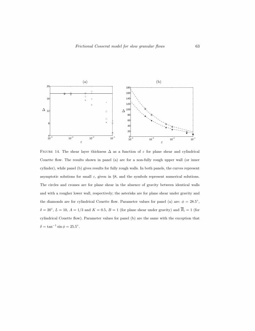
The variation of ∆ with ε is shown in figure 14 for plane and cylindrical Couette flow;
panel (a) shows the results for non-fully rough walls and panel (b) for fully rough walls.
The symbols are the numerical results obtained by the procedure described in §5-6, and
the lines are the asymptotic solutions. For non-fully rough walls, the shear layer thickness
for all the four problems converges to the common asymptote of ∆ ≈ 17.67 as ε→ 0, as
Page 35
Frictional Cosserat model for slow granular flows 35
shown in figure 14a. For shear between fully rough walls, the numerical solutions for ∆
asymptote to the forms given by (8.5) as ε→ 0.
9. Other models
Models for the shear of dense granular materials have also been proposed recently by
Savage (1998) and Bocquet et al. (2000). Here we briefly discuss some aspects of their
models.
9.1. The model of Savage (1998)
In a recent paper, Savage (1998) proposed a model that attempts to merge the critical
state theory for quasistatic flows with the results from kinetic theory for rapid flows,
with the stated primary aim of predicting the behaviour of transitional and rapid flows.
The model starts with a yield condition and an associated flow rule (as in this work), but
Savage argues that the rate of deformation tensor D at any location fluctuates in time,
with a standard deviation ǫ. The mean stress tensor 〈σ〉 is determined by computing
its average with respect to a Gaussian distribution of deformation rates. In the limit
|〈Dij〉| ≪ ǫ, whereDij is a component of D, a Newtonian constitutive relation is obtained
for 〈σ〉, with the shear viscosity given by σcA/ǫ, where σc is the frictional mean stress at
a critical state and A is a material constant. In order to obtain a theory which resembles
kinetic theories for rapid flow, it is assumed that σc may be replaced by σc1(ν)+σc2(ν, T ).
Here σc1 is the frictional mean stress, σc2 is the mean stress obtained from kinetic theory,
and T is the grain temperature or equivalently, the kinetic energy of velocity fluctuations.
To proceed further, it is assumed that ǫ is proportional to√T , and the proportionality
constant is determined by matching the form obtained for large values of T with the
corresponding kinetic theory result.
The idea of accounting for fluctuations in the deformation rate appears to have merit,
Page 36
36 L. S. Mohan, K. Kesava Rao and P. R. Nott
but we find the following aspects of the model unconvincing. (i) The physical origin of
large fluctuations in the velocity gradients relative to the mean velocity gradients is not
clear. Data bearing on this issue do not appear to be available in the literature. (ii)
Even though the constitutive relations are derived by assuming that |〈Dij〉| ≪ ǫ, this
ratio turns out to be O(1) in the examples discussed in Savage (1998). Thus the theory
is applied beyond its range of validity. As noted by Savage (1998), some of the kinetic
constitutive equations also suffer from this defect when applied to plane shear. (iii) As
the velocity gradients are decomposed into mean values and fluctuations, it appears that
the inertial terms, which involve products of velocity fluctuations, may contribute non-
zero terms to the averaged momentum balances. Such terms have been omitted in the
analysis. (iv) The solution of bounded flow problems requires the specification of the
grain temperature at the boundaries, which is usually unknown a priori ; realistically one
would like to determine the temperature as part of the solution.
9.2. The model of Bocquet et al. (2000)
This is a minor variant of the high density kinetic theory of Haff (1983), though Bocquet
et al. (2000) have arrived at the high density limit using the kinetic theory of Jenkins
& Savage (1983). The only change the authors have made is in proposing a modified
expression for the shear viscosity; this gives a better fit for their data of the grain tem-
perature as a function of the shear rate. Making some simplifying assumptions about the
form of the temperature profile, they determine the velocity profile with three adjustable
parameters. It is shown that the profile provides a good fit to their data for shear in a
cylindrical Couette cell (see figure 11). However, their solution is derived for plane shear,
whereas the data they compare with (and achieve a good fit) is for cylindrical Couette
flow.
More importantly, it seems likely that the underlying assumptions of kinetic theory,
Page 37
Frictional Cosserat model for slow granular flows 37
such a molecular chaos and instantaneous binary collisions will break down in the limit of
small deformation rate and high solids fraction. Therefore, as in the case of Savage’s model
discussed above, it appears that the theory has been used beyond its range of validity.
Even if one were to just view the high density kinetic theory as a phenomenological model,
its applicability to slow granular flow is suspect as it does not yield a rate-independent
stress for small deformation rates.
10. Summary and conclusions
We have shown that our frictional Cosserat model for slow granular flows captures the
formation of thin shear layers in viscometric flows. The principal features of our contin-
uum model are: (1) the presence of a couple stress field, which is a result of tangential
frictional forces between grains; (2) an angular velocity field which is not necessarily
determined by the local vorticity; (3) solution of the balance of angular momentum, in
addition to the balances of mass and linear momentum; (4) the extension of the yield
condition and flow rule used in classical plasticity to incorporate the couple stress and
the angular velocity. By including these features, we incorporate a microscopic length
scale in our model, which determines the thickness of the shear layer.
For plane shear in the absence of gravity, we have considered two cases: in the first, the
two walls are of equal roughness, and in the second, the upper wall is smoother. In the
former, for which the shear rate is symmetric about the mid plane, we find that Cosserat
effects (a finite couple stress, asymmetry of the Cauchy stress tensor and deviation of
the angular velocity from half the vorticity) are maximum near the solid boundaries,
and decay with distance from the boundaries. In the second case, the couple stress is
finite everywhere in the gap, but other Cosserat effects are absent. In both cases, the
velocity fields decay rapidly with distance from the upper wall if the Couette gap is large
Page 38
38 L. S. Mohan, K. Kesava Rao and P. R. Nott
compared to the grain size. If the roughness of the granular medium is exactly equal to
that of the wall, it shears uniformly in the entire gap.
For shear between walls of equal roughness in a gravitational field (and in cylindrical
Couette flow), the couple stress is finite throughout the Couette gap, but other Cosserat
effects are present only in the shear layer near the upper wall (inner cylinder). Here
too the velocity and angular velocities decay rapidly with distance from the upper wall
(inner cylinder). While experimental measurements of the couple stress or asymmetry in
the Cauchy stress have not been reported, our predictions are in good agreement with
the velocity measurements reported recently by Mueth et al. (2000) and Bocquet et al.
(2000).
If the wall roughness is less than that of the granular medium (i.e. tan δ < sinφ), the
shear layer thickness ∆ increases with the Couette gap, but reaches an asymptotic value
independent of the Couette gap in the limit H/dp → ∞ (H and dp are the Couette gap
and grain diameter, respectively). Further, ∆ decreases when the angle of wall friction δ
is reduced, and vanishes when the wall is perfectly smooth, in qualitative agreement with
available experimental data. In the singular case of fully rough walls (tan δ = sinφ), the
material shears uniformly over the entire Couette gap for plane shear in the absence of
gravity; for plane shear under gravity or cylindrical Couette flow, ∆ increases with the
Couette gap as (H/dp)1/3, and does not depend on φ.
Many of the above predictions regarding the behaviour of ∆ have so far not been
confirmed experimentally. We believe that these are important issues to be probed in
future experimental investigations, as they will serve to distinguish between existing
models for slow granular flows. Another prediction we make, also requiring experimental
verification, is that the shear layer is located near the lower wall (outer cylinder) if it
Page 39
Frictional Cosserat model for slow granular flows 39
is sufficiently smoother than the upper wall (inner cylinder), and the material elsewhere
suffers little deformation.
While the predictions of our model are for the particular forms of the constitutive
relations (viz. the yield condition and the flow rule) and the boundary conditions we have
chosen, we believe that the main qualitative features of our results have a general validity.
For instance, the yield condition (2.4a) is a modification of the extended von Mises yield
condition, a relation between the first and second invariants of σ; by incorporating the
couple stress in this relation, we introduce a microscopic length scale naturally into
the constitutive relations. Any other yield condition, such as that proposed by Lade &
Duncan (1975) (extended to allow critical states) which involves also the third invariant,
could also be modified in the same spirit, and the qualitative effect would be the same:
the microscopic length scale will set the length scale for the thickness of the shear layer.
In cylindrical Couette flow, our model predicts a small increase in the solids fraction
(depending on the magnitude of the Froude number C) as we move towards the outer
cylinder. This increase, however, is substantially smaller than what was observed in the
experiments of Mueth et al. (2000). This defect may perhaps be corrected by incorporat-
ing elastic effects in the model, which is a direction worthy of further study. For example,
Tejchman & Gudehus (2001) have found that the use of a Cosserat model based on hy-
poplasticity permits the density to vary across the shear layer. Nevertheless, we believe
that our model is a natural extension of classical plasticity models for slow granular flows.
While the models of Bocquet et al. (2000) and Savage (1998) also attempt to explain
thin shear layers, they do not yield a rate independent stress, which has shown to be
an important characteristic of slow flows. In any case, further experiments are required
to assess the performance of our model and others in various flow problems, before
attempting to decide which model, if any, is more realistic.
Page 40
40 L. S. Mohan, K. Kesava Rao and P. R. Nott
Appendix A. Asymptotic solution for small ε
To determine the asymptotic behaviour for small ε, we seek a perturbation solution of
the form
m = m(0) + εm(1) + ε2m(2) + . . . (A 1)
for the couple stress, and similarly for the other fields. For each of the problems con-
sidered, we derive only the leading order solutions of O(ε0) for the stress and velocity
fields, as they suffice to determine the shear layer thickness. However, we ensure that
the asymptotic expansion is uniformly valid by checking that the ratio m(1)/m(0) is O(1)
everywhere in the domain 0 < ξ < 1.
A.0.1. Plane shear in the absence of gravity
On substituting (A 1) in (5.3), we find that the leading order solution for the stresses
are
σ(0)xy = σyx = − tan δ, (A 2a)
m(0) = m0 ≡√
b2 − a2, (A 2b)
and the solutions at all higher orders in ε vanish. The constants a and b are defined in
(5.4). This asymptotic solution is valid only in the outer region ξ− 1/2 ≫ ε; in the inner
region (ξ− 1/2) ∼ ε, m deviates from m0 to satisfy the first of (5.1), as evident from the
exact solution (5.5). For fully rough walls, m0 = 0, and hence (A 2) is a uniformly valid
solution as it satisfies the boundary condition m(1/2) = 0.
The ω and u fields in the outer region are obtained from (3.17)-(3.18) and (A2),
yielding
ω =−1/2
ε(K + 2/k)exp (−k(1 − ξ)/ε) , (A 3a)
u =1
2
(
1 +2/k
(K + 2/k)exp (−k(1 − ξ)/ε)
)
, (A 3b)
Page 41
Frictional Cosserat model for slow granular flows 41
where k is defined in (5.8d). Thus, the linear and angular velocities decay rapidly with
distance from the walls. The variation of m within the inner region near ξ = 1/2 has
little influence on the velocity and fields, as they are negligibly small within this region.
When the two walls are of different roughness, the exact solution is given in §5.1. The
couple stress is constant, m = m0, regardless of ε, and the solutions for ω and u given in
(5.8b) reduce in the asymptotic limit to
ω =−1
ε(K + 2/k)exp (−k(1 − ξ)/ε) (A 4a)
u =2/k
(K + 2/k)exp (−k(1 − ξ)/ε) (A 4b)
It should be noted that if the couple stress at the lower wall is changed by replacing
(4.4) with an alternative boundary condition (see §4), the asymptotic solution for m in
the outer region ξ ≫ ε will still be m = m0, but the solution in the inner region ξ ∼ ε
will be different. However, the velocity fields are affected only by the couple stress in the
outer region, as they decay rapidly with distance from the upper wall, and therefore the
boundary condition for m at ξ = 0 does not influence the velocity profile in the limit
ε→ 0.
A.0.2. Plane shear under gravity
An equation for the couple stress, similar to (5.3) for zero gravity, can be obtained by
combining the yield condition and the angular momentum balance, to get
α εdm
dξ= −a+
(
b2 + c2[
(1 +Bν(1 − ξ))2 − 1]
−m2)1/2
, (A 5)
where c2 = sin2 φ/(2A+ 2), and a and b are defined in (5.4).
Substituting (A 1) in (A 5), the solution at the first two orders in ε is
m(0) =(
m20 + c2
[
(1 +Bν(1 − ξ))2 − 1] )1/2
, (A 6a)
m(1) =a c2α
m(0)2
[
B2ν2(1 − ξ) +Bν]
, (A 6b)
Page 42
42 L. S. Mohan, K. Kesava Rao and P. R. Nott
with m0 defined in (A 2b). Unlike in §A.0.1, the expression for m(0) above is valid in
the entire domain 0 < ξ < 1, as it satisfies the boundary condition (4.4) at the lower
wall. To determine if the expansion is uniformly valid, we inspect the ratio εm(1)/m(0).
When tan δ < sinφ, the ratio is O(ε). Thus the above asymptotic expansion is uniformly
valid when the walls are not fully rough. The leading order solutions for the velocity and
angular velocity, obtained by integrating (3.17) and (3.18) are,
ω(0) = ω1 exp
(
−kε
∫ 1
ξ
(
1 + (c
m0)2[
(1 +Bν(1 − ξ′))2 − 1]
)1/2
dξ′
)
, (A 7a)
u(0) = −2
∫ ξ
0
ω(ξ′)dξ′, (A 7b)
where ω1 = ω(1) and k is defined in (5.8d). To simplify the above expressions, we antic-
ipate the rapid decay of the velocity within a region of thickness O(ε) from the upper
wall, substitute ξ = (1− ξ)/ε and expand the above expressions in ε. Retaining only the
leading order terms for consistency, we get expressions for the velocity fields which are
identical to (A 4), the latter corresponding to shear in the absence of gravity.
For the singular case of fully rough walls (tan δ = sinφ), m(0)(1) = 0. Hence the
asymptotic expansion (A 6) is not valid in a region near the upper wall where (1 − ξ) ∼
ε2/3, because the ratio εm(1)/m(0) is O(1) within this region. Noting that the scaling
for the latter is exactly what we obtained for flow through a vertical channel (Mohan
et al. 1999), we follow the same procedure to determine a uniformly valid asymptotic
expansion in the entire domain 0 < ξ < 1.
To determine the solution within the inner region near the upper wall, we follow the
prescription of Van Dyke (1964, p. 104) and introduce the following rescaled variables
ξ = (1 − ξ) ε−2/3
(
L2
2Bν
)−1/3
, m = mε−1/3(4aαBνc2)−1/3, (A 8)
and seek a solution a solution of the form m = m(0) + f(ε)m(1) + . . . . Upon substituting
Page 43
Frictional Cosserat model for slow granular flows 43
the above in (A 5), we get at leading order
−dm(0)
dξ+ (m(0))2 − ξ = 0. (A 9)
This is a Riccati equation, whose solution can be written in terms of the Airy functions
(Bender & Orszag 1984, p. 20, 569),
m(0) = − d
dξln(
c1Ai(ξ) + c2Bi(ξ))
. (A 10)
where Ai(ξ) and Bi(ξ) are the two independent Airy functions and c1 and c2 are constants
of integration. The constants are determined by matching the inner and outer solutions
in an overlap region, as suggested by Van Dyke (1964, p. 105). Upon writing the outer
solution ( A 6a) in terms of the inner variable ξ and expanding for small ε, we determine
the leading order term to be (4aαBνc2)1/3ε1/3 ξ1/2. This must match with the leading
order outer expansion of the inner solution, which is
−(4aαBνc2)1/3 ε1/3 ξ1/2 if c1 = 0, and (4aαBνc2)1/3 ε1/3 ξ1/2 if c2 = 0. (A 11)
Hence c2 = 0 and the solution at leading order in the inner region is
m(0) = −ε1/3 (4aαBνc2)1/3
Ai(ξ)
d
dξ(Ai(ξ)), (A 12)
from which we may derive the uniformly valid (additive) composite solution in the entire
domain,
m(0) = c(
[1 +Bν(1 − ξ)]2 − 1)1/2 − (A 13)
ε1/3 (4aαBνc2)1/3
Ai(ξ)
d
dξ(Ai(ξ)) − (2Bνc2(1 − ξ))1/2.
In the same manner, the uniformly valid solutions for the velocity fields at the leading
order are found to be
ω = ω1
(
Ai(ξ)
Ai(0)
)2
, (A 14a)
u− u1 = ε2/3
(
L2
2Bν
)1/3
2ω1I(ξ), (A 14b)
Page 44
44 L. S. Mohan, K. Kesava Rao and P. R. Nott
where ω1 = ω(1), u1 = u(1) and
I(ξ) ≡ (Ai(0))−2
∫ ξ
0
(Ai(z))2dz. (A 15)
Enforcing the boundary condition u(0) = 0 and the velocity boundary condition (4.6) at
the upper wall, the angular velocity and velocity at the wall can be determined, giving
to leading order
ω1 =−ε−2/3
2
(
L2
2Bν
)−1/31
I(∞), u1 = 1. (A 16a,b)
The uniformly valid velocity profile to leading order therefore is
u = 1 − I(ξ)/I(∞). (A 17)
A.0.3. Cylindrical Couette flow
Subtracting (6.11) from (6.9) and integrating, we get the following relation between
the shear stress σrθ and the couple stress,
σrθ =− tan δ
(1 + ξ/Ri)2
+ 2(A+ 1)ε α
(
m
(Ri + ξ)− m(0)Ri
(Ri + ξ)2
)
. (A 18)
At O(ε0), (6.11) and (A18) result in σθr = σrθ = − tan δ/(1 + ξ/Ri)2, which when
substituted in the yield condition (6.5) gives the leading order couple stress,
m(0) = −(
m20 + d2
[
1 − 1
(1 + ξ/Ri)4
])1/2
(A 19)
where d2 = tan2 δ/2(A+ 1). At O(ε), (6.5) and (6.11), together with (A 18) yield,
m(1) =aα
(m(0))2 Ri (1 + ξ/Ri)3
(
m20 + d2
[
1 − 3
(1 + ξ/Ri)4
])
− 2aαm(0)(0)
m(0)Ri (1 + ξ/Ri)4
(A 20)
Here too εm(1)/m(0) ∼ O(ε), except when tan δ = sinφ. Therefore the above expansion is
uniformly valid when the wall is not fully rough. On integrating (6.6)–(6.7) and expanding
the results for the region ξ ∼ ε near the inner cylinder, we see that the leading order
velocity fields are again identical to (A 4).
Page 45
Frictional Cosserat model for slow granular flows 45
As in §A.0.2, the above asymptotic expansion for m is not uniformly valid when the
inner cylinder is fully rough, as the ratio εm(1)/m(0) is O(1) in the inner region ξ ∼ ε2/3.
A solution in the inner region may be found by re-scaling the variables,
ξ = ξ ε−2/3
(
L2Ri
4
)−1/3
, m =m
dε−1/3
(
4L
Ri
)
−1/3
, (A 21)
yielding the following equation for m(0):
dm(0)
dξ+ (m(0))2 − ξ = 0. (A 22)
Following the procedure given in §A.0.2, the uniformly valid expression for the couple
stress is
m(0) = − d
(
1 − 1
(1 + ξ/Ri)4
)1/2
+ ε1/3 d (4L/Ri)1/3
Ai(ξ)
d
dξ(Ai(ξ)) + d(4ξ/Ri)
1/2, (A 23)
and for velocity fields is
ω =−ε−2/3
2
(
L2Ri
4
)−1/31
I(∞)
(
Ai(ξ)
Ai(0)
)2
, (A 24a)
u = −1 + I(ξ)/I(∞), (A 24b)
where I(ξ) is defined by (A15).
Page 46
46 L. S. Mohan, K. Kesava Rao and P. R. Nott
REFERENCES
Albert, R., Pfeifer, M. A., Barabasi, A. & Schiffer, P. 1999 Slow drag in a granular
medium. Phys. Rev. Lett. 82, 205–208.
Albert, R., Tegzes, P., Kahng, B., Albert, L., Sample, J., Pfeifer, M., Barabasi, A.,
Vicsek, T. & Schiffer, P. 2000 Jamming and fluctuations in granular drag. Phys. Rev.
Lett. 84, 5122–5125.
Bender, C. M. & Orszag, S. A. 1984 Advanced Mathematical Methods for Scientists and
Engineers. Singapore: McGraw Hill.
Besdo, D. 1974 Ein beitrag zur nichtlinearen theorie des Cosserat-kontinuums. Acta Mech. 20,
105–131.
Bocquet, L., Losert, W., Schalk, D., Lubensky, T. C. & Gollub, J. P. 2000 Granular
shear flow dynamics and forces: experiment and continuum theory. Cond-mat 0012356.
de Borst, R. 1993 A generalisation of the J2-flow theory for polar continua. Comp. Methods
in Appl. Mech. and Engng 103, 347–362.
Brennen, C. & Pearce, J. C. 1978 Granular material flow in two dimensional hoppers. ASME
J. of Appl. Mech. 45, 43–50.
Budny, T. J. 1979 Stick-slip friction as a method of powder flow characterization. Powder
Technol. 23, 197–201.
Campbell, C. S. 1993 Boundary interaction for two-dimensional granular flows. Part 1. Flat
boundaries, asymmetric stresses and couple stresses. J. Fluid Mech. 247, 111–136.
Cleaver, J. A. S. & Nedderman, R. M. 1993 Theoretical prediction of stress and velocity
profiles in conical hoppers. Chem. Engng Sci. 48, 3693–3702.
Dahler, J. S. 1959 Transport phenomena in a fluid composed of diatomic molecules. J. Chem.
Phys 30, 1447–1475.
Gudehus, G. & Tejchman, J. 1991 Some mechanisms of a granular mass in a silo-model tests
and a numerical Cosserat approach. In Advances in Continuum Mechanics (ed. O. Bruller,
V. Mannel & J. Najar), pp. 178–194. Springer.
Haff, P. K. 1983 Grain flow as a fluid-mechanical phenomenon. J. Fluid Mech. 134, 401–430.
Page 47
Frictional Cosserat model for slow granular flows 47
Howell, D., Behringer, R. P. & Veje, C. 1999 Stress fluctuations in a 2d granular couette
experiment: a continuous transition. Phys. Rev. Lett. 82, 5241–5244.
Jackson, R. 1983 Some mathematical and physical aspects of continuum models for the motion
of the granular materials. In Theory of Dispersed Multiphase Flow (ed. R. E. Meyer), pp.
291–337. New York: Academic Press.
Janssen, H. A. 1895 Versuche uber getriededruck in silozellen (on the measurement of pressures
in grain silos). Z. Ver. Deut. Ing. 39, 1045–1049.
Jaunzemis, W. 1967 Continuum Mechanics. New York: The Macmillan Company.
Jenkins, J. T., Cundall, P. A. & Ishibashi, I. 1989 Micromechanical modeling of granular
materials with the assistance of experiments and numerical simulations. In Powders and
Grains (ed. Biarez & Gourves), pp. 257–264. Netherlands: A. A. Balkema.
Jenkins, J. T. & Savage, S. B. 1983 A theory for the rapid flow of identical, smooth, nearly
elastic, spherical particles. J. Fluid Mech. 130, 187–202.
Kaza, K. R. 1982 The mechanics of flowing granular materials. PhD thesis, University of
Houston.
Lade, P. V. & Duncan, J. M. 1975 Elastoplastic stress-strain theory for cohesionless soil. J.
Geotech. Engng. Div., ASCE. 101, 1037–1053.
Lippmann, H. 1995 Cosserat plasticity and plastic spin. Appl. Mech. Rev. 48, 753–762.
Michalowski, R. L. 1987 Flow of granular media through a plane parallel/converging bunker.
Chem. Engng Sci. 42, 2587–2596.
Mohan, L. S., Nott, P. R. & Rao, K. K. 1997 Fully developed flow of coarse granular
materials through a vertical channel. Chem. Engng Sci. 52, 913–933.
Mohan, L. S., Nott, P. R. & Rao, K. K. 1999 A frictional cosserat model for the flow of
granular materials through a vertical channel. Acta Mech. 138, 75–96.
Mueth, D. M., Georges, F. D., Greg, S. K., Peter, J. E., Nagel, S. R. & Jaeger, H. M.
2000 Signatures of granular microstructure in dense shear flows. Cond-mat 00034333.
Muhlhaus, H. B. 1986 Shear band analysis in granular materials by Cosserat theory. Ing.
Archiv. 56, 389–399.
Page 48
48 L. S. Mohan, K. Kesava Rao and P. R. Nott
Muhlhaus, H. B. 1989 Application of cosserat theory in numerical solution of limit load prob-
lems. Ing. Arch. 59, 124–137.
Muhlhaus, H. B. & Vardoulakis, I. 1987 The thickness of shear bands in granular materials.
Geotechnique 37, 271–283.
Munch-Andersen, J. & Askegaard, V. 1993 Silo model tests with sand - and grain. In Proc.
RELPOWFLO II . Norway.
Nasuno, S., Kudrolli, A., Bak, A. & Gollub, J. 1998 Time-resolved studies of stick-slip
friction in sheared granular layers. Phys. Rev. E 58, 2161–2171.
Natarajan, V. V. R., Hunt, M. L. & Taylor, E. D. 1995 Local measurements of velocity
fluctuations and diffusion coefficients for a granular material flow. J. Fluid Mech. 304,
1–25.
Nedderman, R. M. 1992 Statics and Kinematics of Granular Materials. Cambridge: Cambridge
University Press.
Nedderman, R. M. & Laohakul, C. 1980 The thickness of shear zone of flowing granular
materials. Powder Technol. 25, 91–100.
Nott, P. R. 1991 Analysis of granular flow in aerated and vibrated chuetes. PhD thesis, Prince-
ton University.
Petzold, L. 1983 Automatic selection of methods for solving stiff and nonstiff systems of
ordinary differential equations. SIAM J. Sci. Stat. Comput. 4, 136–148.
Savage, S. B. 1998 Analyses of slow high-concentration flows of granular materials. J. Fluid
Mech. 377, 1–26.
Schofield, A. N. & Wroth, C. P. 1968 Critical State Soil Mechanics. London: McGraw-Hill.
Tardos, G. I., Khan, M. I. & Schaeffer, D. G. 1998 Forces on a slowly rotating, rough
cylinder in a couette device containing a dry, frictional powder. Physics of Fluids 10, 335–
341.
Tejchman, J. & Gudehus, G. 1993 Silo-music and silo-quake experiments and a numerical
Cosserat approach. Powder Technol. 76, 201–212.
Tejchman, J. & Gudehus, G. 2001 Shearing of a narrow granular layer with polar quantitites.
Intl. J. Num. Anal. Methods Geomech 25, 1–28.
Page 49
Frictional Cosserat model for slow granular flows 49
Tejchman, J. & Wu, W. 1993 Numerical study of patterning of shear bands in a Cosserat
continuum. Acta Mech. 99, 61–74.
Tejchman, J. & Wu, W. 1994 Numerical study on sand and steel interfaces. Mech. Res. Comm.
21 (2), 109–119.
Tuzun, U. & Nedderman, R. M. 1985 Gravity flow of granular materials round obstacles—II.
Chem. Engng Sci. 40, 337–351.
Van Dyke, M. 1964 Perturbation Methods in Fluid Mechanics. New York: Academic Press.
Page 50
50 L. S. Mohan, K. Kesava Rao and P. R. Nott
V
H
N
g
x
y
Figure 1. Plane shear between parallel walls. The lower wall is stationary and the upper wall
moves at a constant speed V . A constant normal stress N is applied on the upper wall. The
angles of wall friction of the lower and upper walls are δL and δ, respectively.
Page 51
Frictional Cosserat model for slow granular flows 51
(a) (b)
0 0.2 0.4 0.6 0.8 10
0.2
0.4
0.6
0.8
1
δ = 25.5°20° 10° 5°
ξ
u−0.25 −0.15 −0.05 0.05
0
0.2
0.4
0.6
0.8
1
ξ
ω + 1/2dudξ
(c) (d)
−0.1 0 0.1 0.2 0.3 0.4 0.5 0.60
0.2
0.4
0.6
0.8
1
ξ
σyx − σxy
−0.4 −0.3 −0.2 −0.1 0 0.1 0.2 0.30
0.2
0.4
0.6
0.8
1
ξ
m
Figure 2. Results of the Cosserat model for shear between identical walls in the absence of
gravity, for different values of the angle of wall friction δ. Panel (b) shows the difference between
ω and half the vorticity (−1/2 du/dξ), and panel (c) shows the asymmetry in the shear stress.
The material shears uniformly when the walls are fully rough (solid line). The thickness of the
shear layer decreases as the difference between sin φ and tan δ increases. Parameter values are:
φ = 28.5◦, ε = 0.04, L = 10, A = 1/3 and K = 0.5.
Page 52
52 L. S. Mohan, K. Kesava Rao and P. R. Nott
(a) (b)
0 0.2 0.4 0.6 0.8 10
0.2
0.4
0.6
0.8
1
δ = 25.5°20° 10°
ξ
u−6 −4 −2 0 20
0.2
0.4
0.6
0.8
1
ξ
ω
Figure 3. The velocity and angular velocity profiles for plane shear in the absence of gravity
when the lower wall is rougher than the upper wall, i.e. δL > δ. For this problem, the stress
is symmetric, the couple stress is constant (see eqn. 5.7), and the angular velocity is equal to
half the vorticity. The material shears uniformly when the upper wall is fully rough (solid line).
Other parameters are given in the caption of figure 2.
Page 53
Frictional Cosserat model for slow granular flows 53
(a) (b)
0 0.2 0.4 0.6 0.8 10.9
0.92
0.94
0.96
0.98
1
ξ
u−100 −80 −60 −40 −20 00.9
0.92
0.94
0.96
0.98
1
ξ
ω
Figure 4. Comparison of the asymptotic solutions (for small ε) for the (a) linear velocity and (b)
angular velocity fields with their respective numerical solutions, for plane shear in the absence of
gravity. The solid line and circles represent numerical and asymptotic solutions, respectively, for
shear between identical walls. The dashed line and diamonds represent numerical and asymptotic
solutions, respectively, for the case of a rougher lower wall. Parameter values are: φ = 28.5◦,
δ = 20◦, ε = 10−3, L = 10, A = 1/3 and K = 0.5.
Page 54
54 L. S. Mohan, K. Kesava Rao and P. R. Nott
(a) (b)
0 0.05 0.1 0.15 0.2 0.25 0.3 0.350
0.2
0.4
0.6
0.8
1
ξ
m0 0.2 0.4 0.6 0.8 1
0
0.2
0.4
0.6
0.8
1
ξ
u
Figure 5. Effect of m(0), the boundary condition for the couple stress, on the (a) couple stress
and (b) linear velocity fields, for shear in the absence of gravity. The curves are for four values
of m(0) in the allowed range 0 < m(0) < b; the solid line is for m(0) = b. The velocity profiles
for all the cases are indistinguishable. Here δ = 10◦, δL > δ, and other parameters are given in
the caption of figure 2.
Page 55
Frictional Cosserat model for slow granular flows 55
(a) (b)
0 0.2 0.4 0.6 0.8 10
0.2
0.4
0.6
0.8
1
B=0 0.011 5
ξ
u10
−610
−410
−210
00
0.2
0.4
0.6
0.8
1
ξ
ω + 1/2dudξ
(c) (d)
−0.5 −0.4 −0.3 −0.2 −0.1 00
0.2
0.4
0.6
0.8
1
ξ
σyx − σxy
−0.2 0 0.2 0.4 0.6 0.8 10
0.2
0.4
0.6
0.8
1
ξ
m
Figure 6. Predictions of the model for plane shear between fully rough walls under gravity. Panel
(b) shows the difference between ω and half the vorticity, and panel (c) shows the asymmetry
in the shear stress. The solid line is absent in panel (b) because ω + 1/2 du/dξ = 0 for this case.
The parameter B ≡ (ρpgH)/N , indicates the strength of the gravitational body force. Other
parameters are as in the caption of figure 2.
Page 56
56 L. S. Mohan, K. Kesava Rao and P. R. Nott
(a) (b)
−1 −0.5 0 0.5 10
0.2
0.4
0.6
0.8
1
ξ
u−0.4 −0.2 0 0.2 0.4
0
0.2
0.4
0.6
0.8
1
ξ
m
Figure 7. The asymptotic solutions for small ε compared with the numerical solutions for
plane shear under gravity (solid line and circle), and cylindrical Couette flow (dashed line and
diamond). The lines represent numerical solutions, and the symbols asymptotic solutions. The
walls are fully rough for both cases. Parameter values are: φ = 28.5◦, ε = 10−3, L = 10, A = 1/3,
and K = 0.5. In addition, B = 1 for plane shear and Ri = 1 for cylindrical Couette flow (see
§6).
Page 57
Frictional Cosserat model for slow granular flows 57
ω
H
g
θRi
rz
Figure 8. Schematic figure of cylindrical Couette flow. The outer cylinder is stationary and
the inner cylinder rotates at constant angular velocity ω.
Page 58
58 L. S. Mohan, K. Kesava Rao and P. R. Nott
(a) (b)
−1 −0.5 00
0.2
0.4
0.6
0.8
1
Ri=∞
100 10 1
ξ
u10
−410
−210
00
0.2
0.4
0.6
0.8
1
ξ
ω + 1/2dudξ
(c) (d)
−0.5 −0.4 −0.3 −0.2 −0.1 00
0.2
0.4
0.6
0.8
1
ξ
σrθ − σθr
−0.3 −0.2 −0.1 0 0.10
0.2
0.4
0.6
0.8
1
ξ
m
Figure 9. Profiles of the stress and kinematic fields for shear between fully rough walls in a
cylindrical Couette cell for four values of Ri, the ratio of the inner cylinder radius to the Couette
gap. Panel (b) shows the difference between ω and half the vorticity, and panel (c) shows the
asymmetry in the shear stress. The solid line is absent in panel (b) because ω + 1/2 du/dξ = 0
for this case. Ri = ∞ (solid line) corresponds to plane shear, for which ω is equal to the vorticity
and the Cauchy stress is symmetric. Parameter values are: φ = 28.5◦, ε = 0.04, L = 10, A = 1/3
and K = 0.5.
Page 59
Frictional Cosserat model for slow granular flows 59
(a) (b)
−0.2 0 0.2 0.4 0.6 0.8 10
0.2
0.4
0.6
0.8
1
Model: δ=22.9°Model: δ=21° Mueth et al
ξ
−u
−0.2 0 0.2 0.4 0.6 0.8 10
0.2
0.4
0.6
0.8
1
Model: δ=27.3°Model: δ=25° Mueth et al
ξ
−u
Figure 10. Comparison of model predictions (lines) with the data (symbols) of Mueth et al.
(2000) for shear of (a) mustard seeds and (b) poppy seeds in a cylindrical Couette cell. In the
experiments, a layer of particles was glued to the cylinders. The data points to the left of ξ = 0 in
the figures are the velocity of the glued layer. The dot-dash line represents the model prediction
for fully rough walls (tan δ = sin φ, see eqn. 4.3). See text for other parameters.
Page 60
60 L. S. Mohan, K. Kesava Rao and P. R. Nott
0 0.2 0.4 0.6 0.8 1
0
0.2
0.4
0.6
0.8
1
Model: δ=25.5°Model: δ=23.5°Bocquet et al
ξ
−u
Figure 11. Comparison of model predictions (curves) with the data (symbols) of Bocquet et al.
(2000) for the shear of glass beads in a cylindrical Couette cell. In the experiments, a layer of
particles was glued to the cylinders. The dot-dash line represents the model prediction for fully
rough walls (tan δ = sin φ, see eqn. 4.3). See text for other parameters.
Page 61
Frictional Cosserat model for slow granular flows 61
(a) (b)
0 0.2 0.4 0.6 0.8 10
0.2
0.4
0.6
0.8
1
A=1.00.5 0 −0.5
ξ
u0.1 0.15 0.2 0.25 0.3 0.350
0.2
0.4
0.6
0.8
1
ξ
m
Figure 12. Sensitivity of model predictions to the parameter A in the yield condition (3.16).
The solutions are for plane shear between fully rough walls under gravity with B = 1. As
discussed in §2.0.1, |A| must be ≤ 1, and for the set of parameters used here, solutions do not
exist for A < −0.57. The values of other parameters are as in the caption of figure 2.
Page 62
62 L. S. Mohan, K. Kesava Rao and P. R. Nott
(a) (b)
−0.2 0 0.2 0.4 0.6 0.8 10
0.2
0.4
0.6
0.8
1
K=01 10
ξ
u−2 −1.5 −1 −0.5 00
0.2
0.4
0.6
0.8
1
ξ
ω
Figure 13. Sensitivity of model predictions to the parameter K in the kinematic boundary
condition (4.5). The solutions are for shear between fully rough walls under gravity with B = 1.
As K increases, the slip velocity at the upper wall increases and the magnitude of the angular
velocity at the wall decreases. The stress and couple stress profiles are not affected by the value
of K, and are given by the dotted lines in figure 6. The values of parameters other than K are
as in the caption of figure 2.
Page 63
Frictional Cosserat model for slow granular flows 63
(a) (b)
10−4
10−3
10−2
10−1
4
8
12
16
20
ε
∆
10−4
10−3
10−2
10−1
0
20
40
60
80
100
120
140
160
180
ε
∆
Figure 14. The shear layer thickness ∆ as a function of ε for plane shear and cylindrical
Couette flow. The results shown in panel (a) are for a non-fully rough upper wall (or inner
cylinder), while panel (b) gives results for fully rough walls. In both panels, the curves represent
asymptotic solutions for small ε, given in §8, and the symbols represent numerical solutions.
The circles and crosses are for plane shear in the absence of gravity between identical walls
and with a rougher lower wall, respectively; the asterisks are for plane shear under gravity and
the diamonds are for cylindrical Couette flow. Parameter values for panel (a) are: φ = 28.5◦,
δ = 20◦, L = 10, A = 1/3 and K = 0.5, B = 1 (for plane shear under gravity) and Ri = 1 (for
cylindrical Couette flow). Parameter values for panel (b) are the same with the exception that
δ = tan−1 sin φ = 25.5◦.