SHELL-AND-TUBE HEAT EXCHANGER GEOMETRY MODIFICATION: AN EFFICIENT WAY TO MITIGATE FOULING A. Chambon 1 , Z. Anxionnaz-Minvielle 2 , G. Cwicklinski 2 , N. Guintrand 1 , A. Buffet 3 and B. Vinet 2 1 TOTAL Research & Technology Gonfreville, BP 27, F-76700 Harfleur, France Email: [email protected]2 Univ. Grenoble Alpes, F-38000, Grenoble, France CEA, LITEN, Laboratory of Heat Exchangers and Reactors Email: [email protected]3 TECHNIP, 6-8 Allée de l’Arche, F-92973 Paris La Défense, France Email: [email protected]ABSTRACT Crude oil fouling of a shell-and-tube heat exchanger sized according to TEMA standard is compared to a No-Foul design under industrial operating conditions. For similar operating conditions, TEMA and No-Foul heat exchangers have the same behavior regarding fouling. Since the No-Foul one has less tubes by design for the same heat duty, shear stress is increased. Consequently, the No-Foul heat exchanger is less prone to fouling at the same throughput. Impact of tube bundle geometry is then investigated. Helically-finned tubes are compared to plain tubes in the No- Foul heat exchanger. Under similar operating conditions, fouling rates measured are up to an order of magnitude lower than plain tubes (respectively 10 -11 and 10 -10 m 2 K/J). However, pressure drop across the tube-side in both No-Foul plain and finned setup are increased in comparison to the TEMA heat-exchanger. INTRODUCTION Fouling of heat exchangers is the build-up of fouling layers on the heat transfer surface. Crude oil fouling in refineries causes several operating, financial and safety issues. Before entering the atmospheric column, crude oil is usually heated in the preheat train by recovering heat from hot streams. But thermal performance is reduced by fouling due to an increase of the thermal resistance leading to additional fuel consumption and CO2 emissions. Moreover, the gradually decrease in tube cross-sectional area due to the fouling layer growth requires more pumping power to maintain the throughput. Ultimately fouling can cause a fluid blockage. Before reaching this stalemate, cleaning of heat exchangers is required. It could be performed using chemical or by dismantling and water-jetting the equipment. All these consequences are the root of numerous additional expenditures. Costs linked to fouling are estimated to USD3.6 billion a year (Coletti and Hewitt, 2014). Unfortunately, fouling phenomenon remains still not well understood. Therefore, several mitigations techniques have been explored to manage fouling in preheat train such as optimization of operating conditions, preheat train monitoring to optimize cleaning cycles (Müller-Steinhagen et al., 2011; Ishiyama et al., 2010), use of chemicals (Baxter et al., 2004; Brant et al., 2009), tube inserts (Aquino et al., 2007; Krueger and Pouponnot, 2009), etc. This study focuses particularly on the technique of enhanced heat exchanger geometries. Shell-and-tube heat exchangers are commonly set up in hydrocarbon services since it is perceived in industry as a safer option (Coletti and Hewitt, 2014). Nevertheless, fouling of other heat exchanger technologies have also been investigated so far. Compact and spiral heat exchangers successfully mitigate fouling (Tamakloe et al., 2013; Wilhelmsson, 2005) by providing higher shear stress at a given flowrate. Shell-and-tube heat exchanger geometry modification (helical baffle, EM-Baffle or twisted tubes) can also help to mitigate fouling but improvement is limited to the shell-side where dead zones are suppressed (Master, 2003; Brignone et al., 2015). However, tube-side geometry modification has received little attention up to date. Yang et al. (2013) and Crittenden et al. (2015) studied the fouling of an enhanced surface (by the mean of an incorporated wire) and compared it to a smooth one. For the same operating conditions, fouling resistance measured were lowered with the enhanced surface. Provost et al. (2013) and Sippel et al. (2015) published a feedback on fouling of internally helically finned tube with quench water of an industrial naphtha cracker. Enhanced tubes did not undergo any significant fouling after 24 months of unit operation. To the authors’ knowledge, no fouling study of these tubes has been carried out with crude oil. That’s why we will study the influence of the sizing method and tube technology on fouling. Hence, fouling propensity of a shell-and-tube heat exchanger sized according to TEMA standards (TEMA, 1968) is compared to a heat exchanger sized with a No-Foul method as described by Bennett and Nesta (2004). Impact of tube bundle technology is secondly addressed by testing successively plain and helically-finned tubes in the No-Foul heat exchanger. Helically-finned tubes – whose geometry features are illustrated in Fig. 1 – are provided by WIELAND. Compared to the plain tubes, internal area is increased by 30% (i.e. Ai,fin / Ai,plain = 1.30). Heat Exchanger Fouling and Cleaning – 2017 ISBN: 978-0-9984188-0-3; Published online www.heatexchanger-fouling.com 127
A. Chambon1, Z. Anxionnaz-Minvielle2, G. Cwicklinski2, N. Guintrand1, A. Buffet3 and B. Vinet2
1 TOTAL Research & Technology Gonfreville, BP 27, F-76700 Harfleur, France Email: [email protected]
2 Univ. Grenoble Alpes, F-38000, Grenoble, France
CEA, LITEN, Laboratory of Heat Exchangers and Reactors Email: [email protected] 3 TECHNIP, 6-8 Allée de l’Arche, F-92973 Paris La Défense, France Email: [email protected]
ABSTRACT
Crude oil fouling of a shell-and-tube heat exchanger
sized according to TEMA standard is compared to a No-Foul
design under industrial operating conditions. For similar
operating conditions, TEMA and No-Foul heat exchangers
have the same behavior regarding fouling. Since the No-Foul
one has less tubes by design for the same heat duty, shear
stress is increased. Consequently, the No-Foul heat
exchanger is less prone to fouling at the same throughput.
Impact of tube bundle geometry is then investigated.
Helically-finned tubes are compared to plain tubes in the No-
Foul heat exchanger. Under similar operating conditions,
fouling rates measured are up to an order of magnitude lower
than plain tubes (respectively 10-11 and 10-10 m2 K/J).
However, pressure drop across the tube-side in both No-Foul
plain and finned setup are increased in comparison to the
TEMA heat-exchanger.
INTRODUCTION
Fouling of heat exchangers is the build-up of fouling
layers on the heat transfer surface. Crude oil fouling in
refineries causes several operating, financial and safety
issues. Before entering the atmospheric column, crude oil is
usually heated in the preheat train by recovering heat from
hot streams. But thermal performance is reduced by fouling
due to an increase of the thermal resistance leading to
additional fuel consumption and CO2 emissions. Moreover,
the gradually decrease in tube cross-sectional area due to the
fouling layer growth requires more pumping power to
maintain the throughput. Ultimately fouling can cause a fluid
blockage. Before reaching this stalemate, cleaning of heat
exchangers is required. It could be performed using chemical
or by dismantling and water-jetting the equipment. All these
consequences are the root of numerous additional
expenditures. Costs linked to fouling are estimated to
USD3.6 billion a year (Coletti and Hewitt, 2014).
Unfortunately, fouling phenomenon remains still not
well understood. Therefore, several mitigations techniques
have been explored to manage fouling in preheat train such
as optimization of operating conditions, preheat train
monitoring to optimize cleaning cycles (Müller-Steinhagen
et al., 2011; Ishiyama et al., 2010), use of chemicals (Baxter
et al., 2004; Brant et al., 2009), tube inserts (Aquino et al.,
2007; Krueger and Pouponnot, 2009), etc. This study focuses
particularly on the technique of enhanced heat exchanger
geometries.
Shell-and-tube heat exchangers are commonly set up in
hydrocarbon services since it is perceived in industry as a
safer option (Coletti and Hewitt, 2014). Nevertheless, fouling
of other heat exchanger technologies have also been
investigated so far. Compact and spiral heat exchangers
successfully mitigate fouling (Tamakloe et al., 2013;
Wilhelmsson, 2005) by providing higher shear stress at a
given flowrate. Shell-and-tube heat exchanger geometry
modification (helical baffle, EM-Baffle or twisted tubes) can
also help to mitigate fouling but improvement is limited to
the shell-side where dead zones are suppressed (Master,
2003; Brignone et al., 2015).
However, tube-side geometry modification has received
little attention up to date. Yang et al. (2013) and Crittenden
et al. (2015) studied the fouling of an enhanced surface (by
the mean of an incorporated wire) and compared it to a
smooth one. For the same operating conditions, fouling
resistance measured were lowered with the enhanced surface.
Provost et al. (2013) and Sippel et al. (2015) published a
feedback on fouling of internally helically finned tube with
quench water of an industrial naphtha cracker. Enhanced
tubes did not undergo any significant fouling after 24 months
of unit operation. To the authors’ knowledge, no fouling
study of these tubes has been carried out with crude oil.
That’s why we will study the influence of the sizing
method and tube technology on fouling. Hence, fouling
propensity of a shell-and-tube heat exchanger sized
according to TEMA standards (TEMA, 1968) is compared to
a heat exchanger sized with a No-Foul method as described
by Bennett and Nesta (2004). Impact of tube bundle
technology is secondly addressed by testing successively
plain and helically-finned tubes in the No-Foul heat
exchanger.
Helically-finned tubes – whose geometry features are
illustrated in Fig. 1 – are provided by WIELAND. Compared
to the plain tubes, internal area is increased by 30% (i.e.
Ai,fin / Ai,plain = 1.30).
Heat Exchanger Fouling and Cleaning – 2017
ISBN: 978-0-9984188-0-3; Published online www.heatexchanger-fouling.com 127
Fig. 1 Geometry description of a helically-finned tube (Ji et
al., 2012).
EXPERIMENTAL SETUP
Fouling rig
The heat exchanger to be tested (the test section) is
settled in a fouling rig described successively by Ratel et al.
(2013) and Chambon et al. (2015) during past issues of this
meeting. So, the features of the rig are not recalled here and
the reader is strongly invited to refer to these former papers
to learn about it.
As in the industrial process, atmospheric tower bottom
(ATB) flows through the shell side to heat up the crude. Oil
used for experiments was sourced from the Black Sea area.
Physical properties and chemical composition of both fluids
are respectively reported in Table 1 and 2.
Table 1. Physical properties of the oil and the ATB. Physical properties at 300°C Oil ATB
Density (kg/m3) 675 789
Dynamic viscosity (104 N s/m2) 3.69 7.98
Thermal conductivity (102 W/m/K) 9.14 9.11
Heat capacity (J/kg/K) 2 990 2 884
Table 2. Chemical composition of the oil and the ATB. Fluids used for testing: TEMA No-Foul
Oil ATB Oil ATB
Asphaltenes (%w) 1.1 2.5 1.1 0.46
CCR 3.92 5.96 4.45 5.19
Sulphur (%w) 1.22 2.25 1.37 0.56
Coking factor 0.81 2.05 0.77 1.25
Cracking factor (%w) 1.92 2.20 1.99 2.37
Σ C aromatics (%w/w) 17.5 24.5 16.2 17.5
Σ C saturates (%w/w) 82.5 75.6 83.8 82.5
Crude oil and ATB used for No-Foul tests come from a
different batch than that used for TEMA tests, nevertheless
their composition shows a very strong similarity. However,
the ATB used for the No-Foul runs would appear to contain
less sulfur and asphaltenes which are known as fouling
precursors. As a consequence, the ATB should have, a priori,
a less fouling propensity than the one used for TEMA tests.
Heat exchanger designs
The sizing method originally proposed by the TEMA is
known to promote fouling. Fouling resistances listed by the
TEMA are fixed values whereas the fouling is a dynamic
phenomenon which depends on the operating conditions.
These inappropriate values lead to oversize heat exchanger
which, finally, amplifies their fouling. Indeed, the addition of
extra heat transfer surface tends to reduce flow velocities and
the convective heat transfer coefficients and finally increase
the wall temperatures. That’s why Bennet and Nesta (2004)
have developed a sizing method that takes better account of
fouling.
The No-Foul test section is sized to fulfill their
recommendations:
tube-side wall temperature below 300°C and flow
velocity higher than 2 m/s at rated throughput;
on the shell side, leakage currents are minimized
and cross-flow (B-stream) promoted;
over-sizing is reduced to a 15% extra heat transfer
area and no fouling resistance is considered in the
design.
A comparative datasheet in Table 3 gives the
geometrical characteristics of the exchangers tested. Each
tubular heat exchanger tested is made with carbon steel and
has a similar heat flux level and the same tube gauge than the
heat exchanger of a refinery pre-heat train.
Table 3. Geometrical characteristics of the shell-and-tube
heat exchangers compared. Heat exchanger design TEMA No-Foul
Tube bundle Plain Plain Finned
Tube length m 2.0 2.0
Tube outer diameter (do) mm 25.4 25.4
Tube inner diameter (di) mm 19.9 19.9 21.4
Tube count — 32 28
Tube pitch mm 31.75 31.75
Tube arrangement — square square
Tube pass — 4 4
Shell pass — 1 1
Shell internal diameter mm 260 248
Number of baffle — 17 13
Baffle spacing mm 100 115
Baffle window % 20 24
Tube-to-baffle clearance mm 0.9 0.4
Shell-to-baffle clearance mm 2.0 0.9
Heat transfer area (Ao) m2 5.1 4.3
Heat duty W 5 104 5 104
Heat flux W/m2 104 1.2 104
Fouling for sizing m2K/W 1.9 10-3 0
Consequently, at constant flowrate, the No-Foul heat
exchanger requires less heat transfer area than the TEMA in
order to transfer the same duty. This results in fewer tubes.
Hence, the flow velocity and the wall shear stress are
increased, promoting suppression of fouling deposit.
However, the No-Foul exchanger will generate more
pressure drop than the TEMA due to the higher flow
velocities.
Operating conditions range
Crude oil velocities and film temperature investigated
respectively have been selected to be representative of
industrial operating conditions.
Tests are performed in order to investigate effect of film
temperature and velocity separately. After each fouling run,
both sides of the test heat exchanger are flushed with gasoil
Heat Exchanger Fouling and Cleaning – 2017
ISBN: 978-0-9984188-0-3; Published online www.heatexchanger-fouling.com 128
for at least two days in order to remove as fouling material as
possible.
Data reduction
Fouling resistances and fouling rates are derived from
measurements of the overall heat transfer coefficient U(t).
The latter is figured out with Eq. 1 by continuous monitoring
of inlet and outlet temperatures. More details are given in the
previous study (Chambon et al., 2015).
𝑄 = 𝐹 𝑈(𝑡) 𝐴𝑜 𝐿𝑀𝑇𝐷 (1)
In Eq 1, Q is the mean duty derived from hot and cold-
side heat balances. LMTD is the logarithmic mean
temperature difference and F the correction factor. In order
to make reliable fouling propensity comparisons fouling rate
and resistances must be related to the same heat transfer
surface. Since plain and helically-finned tubes have the same
outer diameter (1”), the external heat transfer area (Ao) is
chosen. Hence, all the fouling resistance is affected outside
the tubes albeit it occurs on both sides of the heat exchanger.
Tube wall shear stress, τ, is figured out with Eq. 2, where
ρ and u are respectively crude oil density and velocity.
𝜏 =1
2𝑓𝜌𝑢2 (2)
The Fanning friction factor f is respectively calculated
with Blasius equation (Eq. 3) for plain tubes and with the
Zdaniuk et al. (2008) correlation (Eq. 4) for helically-finned
tubes. In these equations, Re refers to the crude Reynolds
number and N, e, α respectively to the fin height, the number
of fin starts and the helix angle (see Fig. 1).
𝑓 = 0.0791𝑅𝑒−0.25 (3)
𝑓 = 0.128𝑅𝑒−0.035𝑁0.235(𝑒 𝑑𝑖⁄ )0.319𝛼0.397 (4)
The Zdaniuk et al. (2008) correlation has been chosen
since it gives the better agreement with experimental pressure
drop measurements made during a preliminary study.
According to Ebert and Panchal (1995), the film
temperature (Tf) is a weighted average between wall (Tw) and
bulk (Tb) temperature (Eq. 5).
𝑇𝑓 = 𝑇𝑏 + 0.55(𝑇𝑤 − 𝑇𝑏) (5)
Bulk temperature is assumed to be the average between
crude inlet and outlet temperature during the whole run
duration. Wall temperature is derived from Eq. 6.
𝑇𝑤 = 𝑇𝑏 +𝑄
ℎ𝑖𝐴𝑖 (6)
Where hi is the internal convective heat transfer
coefficient and Ai, the effective internal heat transfer area.
Convective heat transfer coefficient is respectively figured
out with Dittus-Boelter (Eq. 7) and Zdaniuk et al. (2008)
correlation (Eq. 8) for plain and helically-finned tubes.
ℎ𝑖𝑑𝑖
𝑘= 0.023𝑅𝑒0.8𝑃𝑟0.4 (7)
ℎ𝑖𝑑𝑖
𝑘= 0.029𝑅𝑒0.653𝑁0.253(𝑒 𝑑𝑖⁄ )0.0877𝑃𝑟0.33 (8)
In these equations, k is the thermal conductivity of crude
oil (see Table 1) and Pr, the crude Prandtl number.
RESULTS AND DISCUSSION
TEMA vs. No-Foul design
Comparison at similar operating conditions. Results
are shown in a temperature-velocity plot in Fig. 2. Tests
performed with the TEMA heat exchanger are labelled with
‘T-P’ whereas ‘NF-P’ refers to the No-Foul one. The label is
followed with the run identification number. If fouling is
detected during a run, relative fouling rate (to the TP-4 test)
is indicated into brackets. Moreover, the size of the circle is
proportional to the measured fouling rate.
The curve plotted represents the threshold conditions
calculated using the Panchal et al. (1999) correlation.
Parameters have been optimized with the fouling rates
measured on both TEMA and No-Foul heat exchanger. This
graph allows to delimit two areas: a fouling area above the
curve and a no-fouling area below the curve.
Fig. 2 Fouling experiment results for the TEMA and No-Foul
heat exchangers as a function of crude oil velocity.
Only tests NF-P2 to NF-P5 can be compared to the
results of the T-P series. Flow velocity and film temperature
of NF-P1 run is too far from T-P4 and T-P8.
The fouling rate of tests NF-P2 and T-P7 are
comparable. Although on NF-P2 the film temperature is
higher, the crude velocity (wall shear stress) is lower and the
ATB cross-flow velocity is 20% lower. The gap could be
explained by a little bit lower fouling propensity of the ATB
(see Table 2).
The absence of fouling for the NF-P3 and T-P2 runs
proves that they are comparable. On test T-P2 a fouling
resistance close to uncertainty was detected while no fouling
was detected on test NF-P3. These observations seem to be
consistent with the lower crude oil temperature and with the
lower fouling propensity of the ATB.
Although test NF-P4 is carried out at a higher
temperature than test T-P1, no fouling is noticed. The
threshold temperature was probably not reached. Referring to
Heat Exchanger Fouling and Cleaning – 2017
ISBN: 978-0-9984188-0-3; Published online www.heatexchanger-fouling.com 129
Fig. 2, the real threshold curve would be positioned above
NF-P4.
For a similar wall shear stress (i.e. oil velocity) on tests
NF-P5 and T-P5, a lower fouling rate was observed for the
NF-P5 test. This is in accordance with the lower film
temperature and highlights the strong impact of temperature
on fouling growth. It is confirmed by comparing NF-P5 and
T-P6 (carried out at lower temperature and similar shear
stress). Therefore, the real threshold curve is assumed to be
located between these two points which is in accordance with
the Panchal et al. (1999) forecast (see Fig. 2).
At low flow velocities and film temperatures, the
equilibrium between deposition and suppression rates is
slower to be reached (slow dynamics). Conversely, at higher
velocities and film temperatures, the equilibrium of the two
mechanisms is more rapidly set up (fast dynamics). Hence,
the Panchal et al. (1999) correlation delineates the fouling
and non-fouling areas poorly when the balance between the
deposition and suppression rate is more difficult to set up.
Forecasts are more accurate for high flow velocities when the
dynamics is more pronounced.
To sum it up, for similar operating conditions (velocity
and film temperature), the TEMA and No-Foul heat
exchangers have the same behavior regarding fouling.
Fouling rate and resistance measured are all included in
measurement uncertainties.
Comparison at same throughput. Similarly to Fig. 2,
results are gathered in Fig. 3 where horizontal axis is now the
crude oil flowrate. This graph allows to compare the fouling
propensity of a shell-and-tube heat exchanger according to
the method used for its sizing.
Fig. 3 Fouling experiment results for TEMA and No-Foul
heat exchangers as a function of crude oil flowrate.
The two threshold curves are plotted with the same
correlation (Panchal et al., 1999) and the same optimized
parameters. They are not superimposed because the threshold
condition depends on the wall shear stress but not directly to
the crude oil flow rate. Indeed, for the same flowrate, wall
shear stress is greater in the No-Foul heat exchanger because
crude oil velocity is higher due to fewer tubes. Consequently,
the No-Foul heat exchanger threshold curve is translated
horizontally to the left-hand side of the graph.
By replacing the TEMA heat exchanger with a No-Foul
one, fouling operating loci located between the two
thresholds curves are moved into the non-fouling area. Thus,
fouling is reduced because operating conditions are now in
the non-fouling zone of the dashed curve.
Cost considerations. No-Foul heat exchangers prove to
be more economical to produce because they are sized as
tightly as possible. Since both exchangers are tubular heat
exchangers, replacing a TEMA with a No-Foul avoid heavy
modification of the unit because the bulk is similar and
nozzle locations can be kept in place. Finally, OPEX costs
are reduced since the No-Foul is less prone to fouling. The
main drawback of the latter design is pressure drop due to the
higher flow velocities at same throughput.
Helically finned vs. plain tube
In this section, the plain tube bundle of the No-Foul heat
exchanger was replaced by a bundle of helically finned tubes.
The two bundles have the same features: same tube count,
same baffle spacing, same outer diameter, etc. The tube
internal geometry is the only modified parameter. The goal is
to compare the fouling propensity of these tubes with respect
to the plain tubes at similar operating conditions.
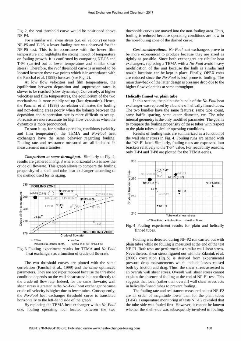
Results of fouling tests are summarized as a function of
the wall shear stress in Fig. 4. Fouling runs are named with
the ‘NF-F’ label. Similarly, fouling rates are expressed into
brackets relatively to the T-P4 value. For readability reasons,
only T-P4 and T-P8 are plotted for the TEMA-series.
Fig. 4 Fouling experiment results for plain and helically
finned tubes.
Fouling was detected during NF-P2 run carried out with
plain tubes while no fouling is measured at the end of the test
NF-F1. Both tests are performed at a similar wall shear stress.
Nevertheless, shear stress figured out with the Zdaniuk et al.
(2008) correlation (Eq. 5) is derived from experimental
pressure drop measurements which include losses caused
both by friction and drag. Thus, the shear stress assessed is
an overall wall shear stress. Overall wall shear stress cannot
explain the absence of fouling at the end of NF-F1 test. This
suggests that local (rather than overall) wall shear stress acts
in helically-finned tubes to prevent fouling.
The fouling rate and resistances measured on test NF-F2
are an order of magnitude lower than for the plain tubes
(T-P4). Temperature monitoring of tests NF-F2 revealed that
the tube-side was fouled first. However, it cannot be known
whether the shell-side was subsequently involved in fouling.
Heat Exchanger Fouling and Cleaning – 2017
ISBN: 978-0-9984188-0-3; Published online www.heatexchanger-fouling.com 130
The ATB processed on test T-P4 is assumed to be more prone
to foul and could explain why fouling is more severe in this
test but it cannot account for the large difference in fouling
rates. The previous hypothesis of higher local shear stress in
helically-finned is believed to explain fouling mitigation.
No fouling resistance was detected on the NF-F3 test,
while a fouling resistance near of the uncertainty was
measured on the T-P8 test. It is unlikely fouling on the T-P8
test is due to the ATB because under similar shell-side
conditions, no fouling was measured in the T-P2 and T-P6
tests. Thus, the fouling resistance on the T-P8 test could only
be due to crude oil. Since the NF-F3 and T-P8 tests are
carried out at the same film temperatures and shear stress, the
higher local shear stress seems, once again, to be the most
likely hypothesis to explain the fouling mitigation.
Helically-finned tubes would appear to be less prone to
fouling than plain tubes, at least for the range of operating
conditions investigated. Fouling of helically-finned tubes has
only been noticed for very low velocities and high film
temperatures. For similar operating conditions, the fouling
rate measured are is one order of magnitude lower than for
plain tubes. However, the relatively short duration of the tests
(300 to 500 h) and the limited number of experimental runs
do not allow to conclude about fouling over the long periods
of time and on other operating ranges.
The comparison of the tests carried out under similar
operating conditions suggests a different rate of foulant
growth which could explain the lower fouling propensity of
helically-finned tubes. Fins could generate boundary layer
detachments and impart swirling flow motion. Thus, at same
film temperature and shear stress, the enhanced local
turbulence would reduce the fouling rate.
However, the mitigation effect of finned tubes is
counterbalanced by a significant increase in pressure drop
compared to the plain tubes. At similar flowrate, the higher
shear stress causes more pressure drop.
CONCLUSIONS
1. For similar operating conditions (velocity and film