30
WLD 113 Shielded Metal Arc Welding Mild Steel II (E7018)
| Date post: | 06-Dec-2015 |
| Category: |
Documents |
| Upload: | greatsteel |
| View: | 21 times |
| Download: | 3 times |

WLD 113 Shielded Metal Arc Welding
Mild Steel II (E7018)

3/28/13 2
Index Course Information Accessing Coursemate and ebook info
3
4
E7018 and CAC Information Sheets
5-9
Craftsmanship Expectations Welding Projects
10
11-23 Final Exam Information
24-27
Assessment Breakdown for the Course
49
This project was supported, in part, by the
National Science Foundation Opinions expressed are those of the authors And not necessarily those of the Foundation

3/28/13 3
Course Assignments Reading
The Welding Principles and Applications: By Larry Jeffus Chapter 6, Advanced Shielded Metal Arc Welding Chapter 9, Related Cutting Processes Chapter 19, Reading Technical Drawings Math
Practical Problems in Mathematics 6th edition by Robert Chasan Chapter 9, Multiplication of Common Fractions Chapter 10, Division of Common Fractions Chapter 11, Division of Common Fractions Chapter 12, Introduction to Decimal Fractions, Rounding, Calculators Recommended assignments
Complete review question following each assigned chapter Quizzes Complete Interactive Quiz in CourseMate for each assigned chapter Video Training Miller #2 Weaving the electrode. Miller #4, Fillet weld Techniques Welding Projects
E7018 Vertical Lap Joint (3F) E7018 Vertical Single V- Groove Weld (3G) E7018 Overhead Bead Plate E7018 Overhead Tee Joint (4F) E7018 Single V- Groove Weld (4G)
Final Exam Part One (Closed Book Exam) Part Two (Practical Exam)
Reference List Science Packet
Time Line: Open-entry, open-exit instructional format allows the student to work at his/her own pace. It’s the student’s responsibility to complete all assignments in a timely manner. See your instructor for assistance. Outcome Assessment Policy:
The student will be assessed on his/her ability to demonstrate the achievement of course outcomes. The methods of assessment may include one or more of the following: oral or written examinations, quizzes, written assignments, visual inspection techniques, welding test, safe work
habits, task performance and work relations.

3/28/13 4
Accessing the Interactive ebook for Principles and Applications and Practical Problems in Mathematics
Here is a link to the publishers website that goes over some “getting started” procedures with CourseMate. http://www.cengage.com/tlconnect/client/product/fcis.do?productId=535 For New Students Your book bundle will contain an access code for both your Principles and Applications book and the Practical Problems in Mathematics. For Returning Students If you have the Seventh Edition of the Principles and Applications book you should have an access code. If not see your instructor. For the math book you will have to go to this site http://www.cengagebrain.com/shop/isbn/9781111313593 and rent the ebook for either a six month or one year option. Your math quizzes will be accessible through Desire 2 Learn. Your Instructor will assist you in accessing this. Course Key There will be a master course key containing all of the courses available on CourseMate. You will find the course you are currently taking and enter the corresponding number in the appropriate area in CourseMate. Note For each class there will be separate Access code and course key for Principles and Applications and Practical Problems in Mathematics

3/28/13 5

3/28/13 6
Low Hydrogen Information Sheet Low Hydrogen Electrodes Low-hydrogen electrodes must be dry if they are to perform properly. Electrodes in unopened, hermetically sealed containers remain dry indefinitely in good storage conditions. Opened cans should be stored in a cabinet at 250 F to 300 F. Low-hydrogen electrodes pick up moisture. The moisture, depending upon the amount absorbed, impairs weld quality in the following ways.
• A small amount of moisture may cause internal porosity. Detection of this porosity requires X-ray inspection or destructive testing. A high amount of moisture causes visible external porosity in addition to internal porosity.
• Severe moisture pickup can cause weld cracks or under-bead cracking in addition to severe porosity.
• If the base metal has high hardenability even a small amount of moisture can contribute to under-bead cracking.
Low-hydrogen Electrodes are available with fast fill and fast freeze Characteristics. When welding out-of-position the molten metal tends to spill out of the joint. To offset this tendency, an electrode with a fast freezing deposit is needed, even though the slag stays molten and has a tendency to spill out. Applications for low-hydrogen electrodes include:
• X-ray-quality welds or welds requiring high mechanical properties. • Crack-resistant welds in medium-carbon to high-carbon steels; welds that resist hot-short
cracking in phosphorus steels; and welds that minimize porosity in sulfur-bearing steels. • Welds in thick sections or in restrained joints in mild and alloy steels where shrinkage
stresses might promote weld cracking. • Welds in alloy steel requiring a minimum tensile strength of 70,000 psi or more. • Multiple-pass vertical, and overhead welds in mild steel.
Vertical Welds: For multi-pass welds, first deposit a root bead by using a slight weave. Deposit additional layers with either a straight up progression or a slight side to side weave. By hesitating at the sides long enough to insure fusion and to minimize undercut if you use a slight side-side oscillation technique. Do not use a whip technique or take the electrode out of the molten pool. Travel slowly enough to maintain the shelf without causing metal to spill. Use current range similar to Horizontal position. Overhead welds: Deposit stringer beads by using a slight circular motion in the crater. Maintain a short arc. Motions should be slow and deliberate. Move fast enough to avoid spilling weld metal, but do not become alarmed if some slag spills. Use currents in the lower portion of the range.
3/28/13 7
Helpful Hints
Arc Length for the E7018 (Low Hydrogen Electrodes) Due to the nature of low hydrogen electrodes it is critical to maintain a short and consistent arc length. This will maximize the shielding gas coverage for the weld puddle. Arc length can be determined by sight and sound.
1st If the arc is too long you will see the globular transfer. 2nd If it is too short you will see slag wanting to explode from the puddle and you’ll hear an electrical humming sound. 3rd The correct arc length will be between those two indicators. The sound of the arc will help determine the arc length too. It will sound much like, “bacon frying in a pan,” a distinct crisp sound. Remember: The general rule for maximum arc length is the distance and should not exceed the diameter of the electrode at any time. If you remember this you’ll never have trouble with porosity.
Heat Control for out of position welding When welding in the vertical or overhead positions gravity can have an effect on the weld contour. This is important for the welder to understand. The key for successful welding in out of position work is heat control. This can be controlled by the following steps:
1. Use lower amperage range. 2. Use stringer bead technique. 3. Keep the base metal cool. Quench metal every 2 to 3 passes. 4. Use a tight arc technique.
Using these steps in conjunction with practice the welder should have success.

3/28/13 8
Carbon Arc Gouging Description Air carbon arc cutting (CAC-A) is a physical means of removing base metal or weld metal by using a carbon electrode and electric arc process with compressed air. In the air carbon arc process, the intense heat of the arc between the carbon electrode and the work piece melts a portion of the base metal, or weld. Simultaneously a jet of air is passed through the arc, of sufficient volume and velocity to blow away the molten material. This sequence can be repeated until the required groove or cut has been obtained. Applications The CAC-A process may be used to prepare plates for welding, to provide a suitable bevel or groove to be welded. It can be used to back gouge a joint prior to welding the second side. Carbon arc provides an excellent means of removing defective welds or misplaced welds. Back Gouging Reasons for Back Gouging:
1. Repairing welds for X-ray quality. 2. When irregular gaps or poor technique produces a poor bead. 3. When a heavy bead is needed to prevent melt-through of semiautomatic fill beads.
Carbon Arc Torch Power sources that can be used for Carbon
Arc process.

3/28/13 9
Generator Power Supply
Gouging Torch
Large Electrode settings
Normal welding range
Overhead & Vertical
Polarity Selection
Select for large electrodes then select amperage range

3/28/13 10
Electrode Locating Groove
Lever for opening Jaw
Compressed air flow hole Holes should face direction of travel
Air Valve Push to open air supply
Connection for Electrode Lead (DCEP)
Connection for Compressed Air supply Air supply must be between 80 psi & 100 psi

3/28/13 11
Various Sizes of Electrodes
Electrodes come in Round, Flat and Semi-Round. Cross Sections of Carbon electrodes
Flat Semi-Round Round
Caution Never cut on any material that might produce fumes that would be hazardous to your
health without proper safety precautions, including adequate ventilation.
Electrodes available as copper-coated or without a coating

3/28/13 12
Craftsmanship Expectations for Welding Projects
The student should complete the following tasks prior to welding: 1. Thoroughly read each drawing. 2. Make a cut list for each project.(Cut enough material for two projects). Check
Oxyacetylene tip for any obstructions clean if necessary for precise cuts. 3. Assemble the welding project to Blue Print Specifications. 4. Review Welding Procedure in upper right hand corner of print. 5. See the instructor for the evaluation.
Factors for grading welding projects are based on the following criteria:
Metal Preparation Project Layout Post Weld Clean-up Oxyacetylene Cut quality Accurate (+/- 1/16”) Remove Slag/Spatter Grind all cut surfaces clean Limit waste Remove sharp edges
This photo shows Bead Placement
Example of a High Quality Weld
Weld Quality per AWS D1.1 VT Criteria Cover Pass
Reinforcement Flush to 1/8” Undercut 1/32” deep
Weld Bead Contour Smooth Transition Overlap None Allowed Cracks None Allowed
Arc Strikes None Allowed Fillet Weld Size See Specification on Print
Porosity None Allowed

3/28/13 13
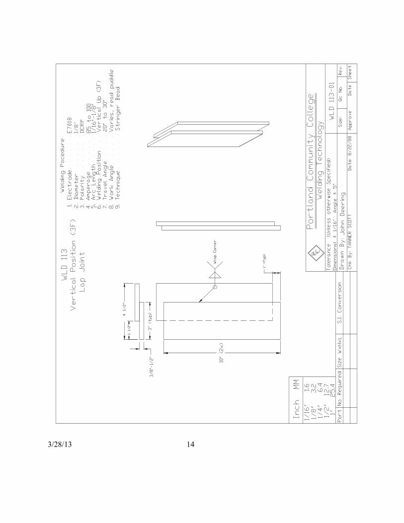
E7018 Vertical Position Lap Joint (3F) Project #1 Technique: When welding in the vertical position, it is important to control the heat input into the base metal. Two primary ways to accomplish this are by using lower amperages and quenching the project often. For multipass welds, first deposit a stringer bead. Deposit additional layers with a slight side-to-side weave, hesitating at the sides long enough to minimize undercut. Travel slowly enough to maintain the weld without causing metal to spill out. Welding Sequence: Wrap the weld around the corner.
Vertical Up Lap Joint
VT Criteria Student Assessment Instructor Assessment Reinforcement (0” –1/8”)
Undercut (1/32”) Weld Bead Contour (Smooth)
Penetration Cracks (none)
Arc Strikes (none) Fusion (complete)
Porosity (none) Grade Date
3/28/13 14

3/28/13 15
E7018 Vertical Position Single V-Groove (3G) - Back Gouge Project #2 Welding Sequence: When running the first pass (root weld) it is important to center the weld so that it has equal dilution into each piece of metal. Deposit additional layers with a slight sided to side weave and hesitating at the sides long enough to minimize undercut. Do not use a whip technique or take the electrode out of the molten pool with the 7018 electrode. Travel slow enough to maintain the weld without causing metal to spill out. Use amperages in the lower portion of the range. You can use a weave or a straight stringer bead technique. After welding out the front side, back gouge the backside with the air carbon arc gouging process and weld it out. The goal of this project is to achieve complete joint penetration (CJP) so be sure to gouge out deep enough and grind out all slag and rough spots.
VT Criteria Student Assessment Instructor Assessment Reinforcement (0” –1/8”)
Undercut (1/32”) Weld Bead Contour (Smooth)
Penetration Cracks (none)
Arc Strikes (none) Fusion (complete)
Porosity (none) Grade Date

3/28/13 16

3/28/13 17
Back Gouge U-Groove (Step Two) Project #2 After welding out the front side, back gouge the backside with the air carbon arc gouging process. Arc out un-fused root until seam lines disappear so that when welded you will obtain complete joint penetration. The goal of this project is to achieve complete joint penetration (CJP) so be sure to gouge out deep enough and grind out all slag and rough spots. Weld up area that has been gouged out.
U-Shaped groove by carbon arcing
VT Criteria Student Assessment Instructor Assessment Reinforcement (0” –1/8”)
Undercut (1/32”) Groove within (+ or - 1/8”) of
being straight
Width and Depth of groove within (+ or – 3/32”)
Penetration Cracks (none)
Arc Strikes (none) Fusion (complete)
Porosity (none) Grade Date

3/28/13 18
Air Carbon Arc Safety In addition to the safety requirements of shielded metal arc, air carbon arc requires several special precautions, such as
• Sparks-The quantity and volume of sparks generated during This process is a major safety hazard. Extra precautions must be taken to insure other workers, equipment, materials, or property in the area will not be affected by the spark stream.
• Noise-This process produces a high level of sound. The sound level is high enough to cause hearing damage if proper ear protection is not used.
• Light-The arc light produced is the same as that produced by the shielded metal arc welding process. But because the arc has no smoke to defuse the light and the amperages are usually much higher, the chances of receiving arc burns are much higher. Additional protection should be worn, such as thicker clothing, a leather jacket, and leather aprons.
• Eyes-Because of the intense arc light, a number 10 shade or darker should be used.
• Fumes- The combination of the air and the metal being removed results in a high volume of fumes. Use well ventilated area. If surface has paint, grease, oil it might generate hazardous fumes.

3/28/13 19
Air Carbon Arc Straight Cut in the Flat position Using an air carbon arc cutting torch and welding power supply that has been safely set up properly. Wearing safety glasses, welding helmet, gloves, and any other required personal protection clothing you will make a 10-inch U-groove gouge in a carbon steel plate just completed. Have your instructor give you a demonstration on use of carbon arc set up and usage.
1. Connect current conductor. 2. Connect compressed air hose 3. Select the amperage setting within the range for the diameter electrode 4. Check to see that the stream of sparks will not start a fire or cause any damage to
anyone or anything in the area. Set-up screen. 5. Set machine for DCRP. 6. Using a good dry leather glove to avoid electrical shock, insert the electrode in the
torch jaws so that about 6 inches is extending outward. Be sure not to touch the electrode to any metal parts, because it may short out.
7. Turn on the air at the torch head. 8. Position your torch where you want to start your gouge. 9. Lower your welding helmet. 10. Slowly bring the electrode down at about a 30 degree angle so it will make
contact with the plate near the starting edge. Be prepared for a loud, sharp sound when the arc starts.
11. Once the arc is struck, move the electrode in a straight line down the plate toward the other end. Just skim the surface no deeper than ¼ inch deep on each pass. Keep the travel speed and angle of the torch constant.
12. When you reach the other end, lift the torch so the arc will stop. 13. Raise your helmet and stop the air. 14. Remove the remaining electrode from the torch so it will not accidentally come in
contact with metal. 15. Turn off equipment and air, clean up your work area when you are finished
gouging. 16. Your gouge should be uniform in width and depth within +or- 1/8 of an inch.
3/28/13 20
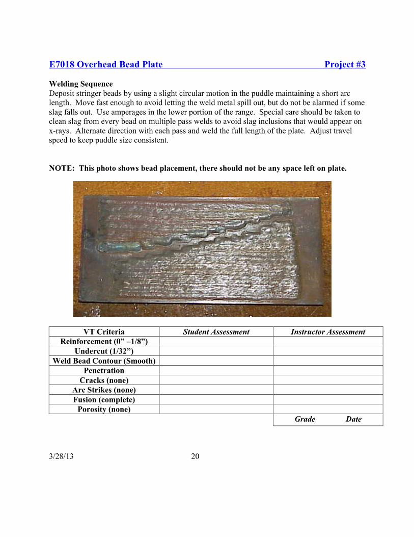
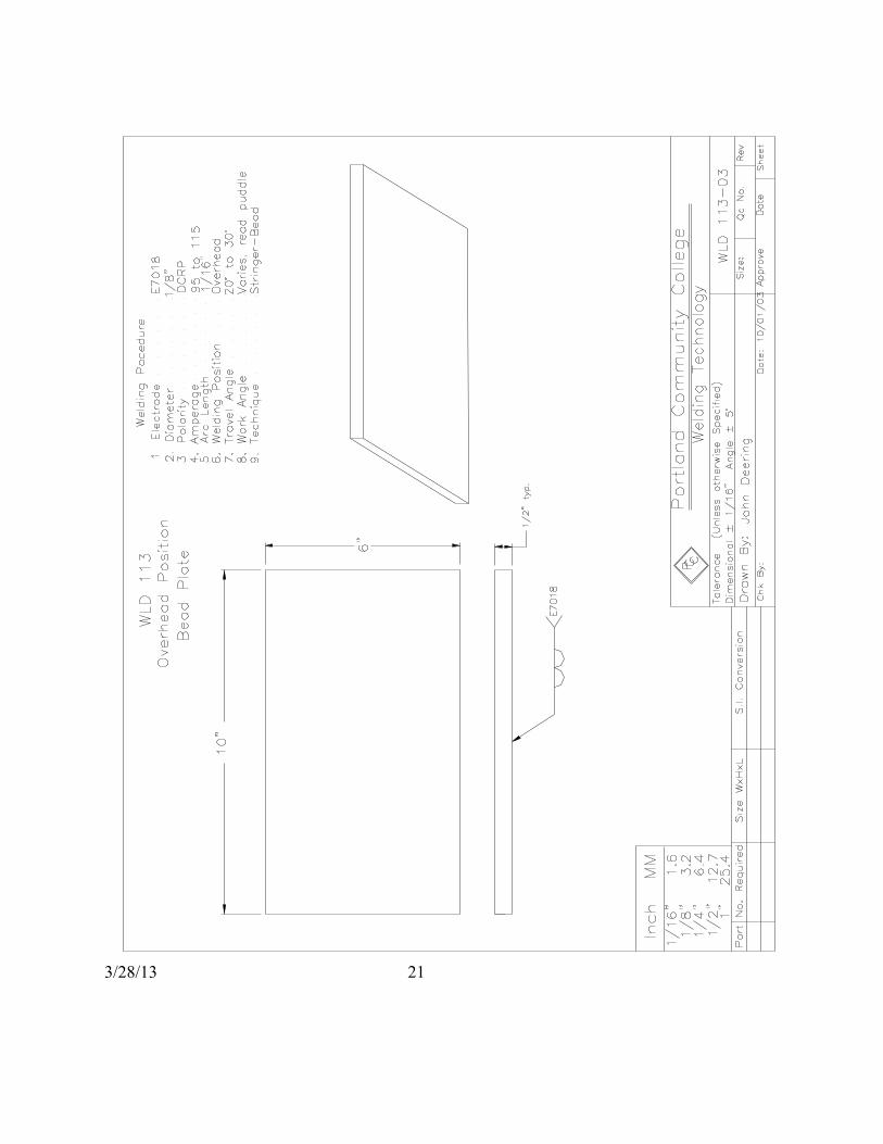
E7018 Overhead Bead Plate Project #3 Welding Sequence Deposit stringer beads by using a slight circular motion in the puddle maintaining a short arc length. Move fast enough to avoid letting the weld metal spill out, but do not be alarmed if some slag falls out. Use amperages in the lower portion of the range. Special care should be taken to clean slag from every bead on multiple pass welds to avoid slag inclusions that would appear on x-rays. Alternate direction with each pass and weld the full length of the plate. Adjust travel speed to keep puddle size consistent.
NOTE: This photo shows bead placement, there should not be any space left on plate.
VT Criteria Student Assessment Instructor Assessment
Reinforcement (0” –1/8”) Undercut (1/32”)
Weld Bead Contour (Smooth) Penetration
Cracks (none) Arc Strikes (none) Fusion (complete)
Porosity (none) Grade Date
3/28/13 21

3/28/13 22
E7018 Overhead T-Joint (4F) Project #4 Welding Sequence for Multiple-pass T-Joints Deposit stringer beads by using a slight oscillation with a short arc length. Oscillation movements should be slow and deliberate. Move fast enough to avoid letting the weld metal spill out of the puddle but do not be alarmed if some slag spills out. When welding the first pass, the tip of the electrode must touch both legs of the T-joint. After the first bead, the bead placement sequence starts on bottom plate first and you work to the top plate. Clean every bead thoroughly before proceeding to next bead.
This photo shows Bead Placement
VT Criteria Student Assessment Instructor Assessment Reinforcement (0” –1/8”)
Undercut (1/32”) Weld Bead Contour (Smooth)
Penetration Cracks (none)
Arc Strikes (none) Fusion (complete)
Porosity (none) Grade Date

3/28/13 23

3/28/13 24
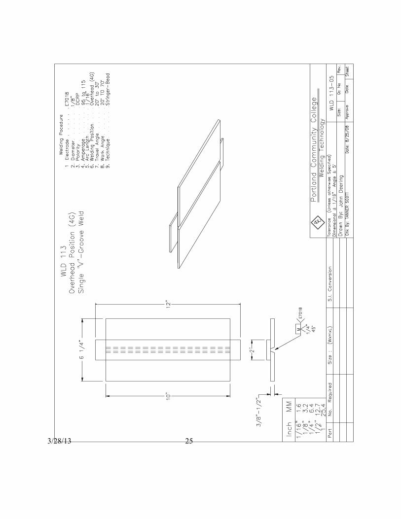
E7018 Overhead V-Groove(4G) Project #5 Welding Sequence Multiple-Pass: Deposit the root pass so that it has equal dilution into each piece of metal using a slight oscillation technique. Weld the second layer using a side to side weave covering the entire root pass. Be sure to pause at the sides of the puddle long enough to cover the whole root pass and to melt out any small slag pockets and to minimize undercut. From this point, use straight stringer beads filling the groove up to just below the top of the base material before applying the cover pass. Care should be taken to clean slag after every pass to avoid slag inclusions that would appear on X-ray. Use stringer beads for the cover pas.
Overhead V-Groove
VT Criteria Student Assessment Instructor Assessment Reinforcement (0” –1/8”)
Undercut (1/32”) Weld Bead Contour (Smooth)
Penetration Cracks (none)
Arc Strikes (none) Fusion (complete)
Porosity (none) Grade Date
3/28/13 25

3/28/13 26
Final Exam This portion of the final exam is a closed book test. You may use the review questions you completed at the end of the assigned chapters as a cheat sheet. Consult with your instructor to determine items that you may need to review. Once you determine that you are ready for the exam, see your instructor.
Study Guide Safety
• Oxyacetylene safety • SMAW safety • Hand Tool Safety
SMAW and OAC Processes • Power source specifics
o Polarity o Current out put o Arc blow
• AWS electrode classification • OAC and CAC-A
o Theory of cutting o Flame types and equipment set-up o Safety
Welding Defects (types and causes) Welding Symbols and Blueprints
• Orthographic views • Isometric views • Welding symbol
o Weld symbols o Reference line o Tail
Math and Math conversions Adding and subtracting fractions Reading a tape measure Metric conversions
3/28/13 27
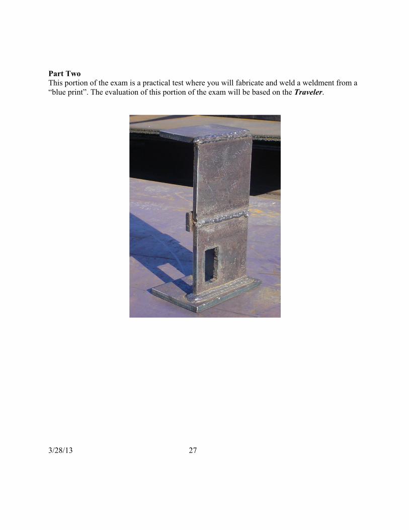
Part Two This portion of the exam is a practical test where you will fabricate and weld a weldment from a “blue print”. The evaluation of this portion of the exam will be based on the Traveler.

3/28/13 28
3/28/13 29
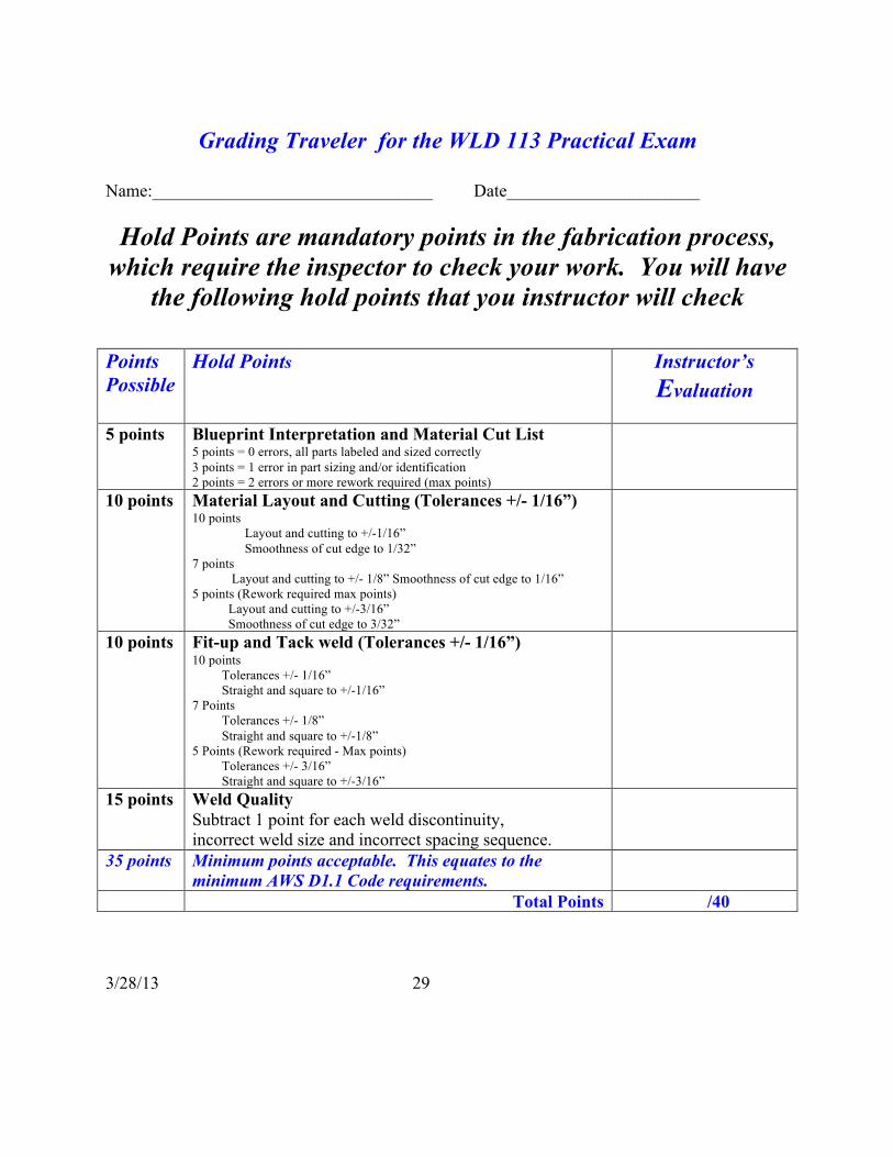
Grading Traveler for the WLD 113 Practical Exam
Name:________________________________ Date______________________
Hold Points are mandatory points in the fabrication process, which require the inspector to check your work. You will have
the following hold points that you instructor will check Points Possible
Hold Points Instructor’s Evaluation
5 points Blueprint Interpretation and Material Cut List
5 points = 0 errors, all parts labeled and sized correctly 3 points = 1 error in part sizing and/or identification 2 points = 2 errors or more rework required (max points)
10 points Material Layout and Cutting (Tolerances +/- 1/16”) 10 points Layout and cutting to +/-1/16” Smoothness of cut edge to 1/32” 7 points Layout and cutting to +/- 1/8” Smoothness of cut edge to 1/16” 5 points (Rework required max points) Layout and cutting to +/-3/16” Smoothness of cut edge to 3/32”
10 points Fit-up and Tack weld (Tolerances +/- 1/16”) 10 points Tolerances +/- 1/16” Straight and square to +/-1/16” 7 Points Tolerances +/- 1/8” Straight and square to +/-1/8” 5 Points (Rework required - Max points) Tolerances +/- 3/16” Straight and square to +/-3/16”
15 points Weld Quality Subtract 1 point for each weld discontinuity, incorrect weld size and incorrect spacing sequence.
35 points Minimum points acceptable. This equates to the minimum AWS D1.1 Code requirements.
Total Points /40
3/28/13 30
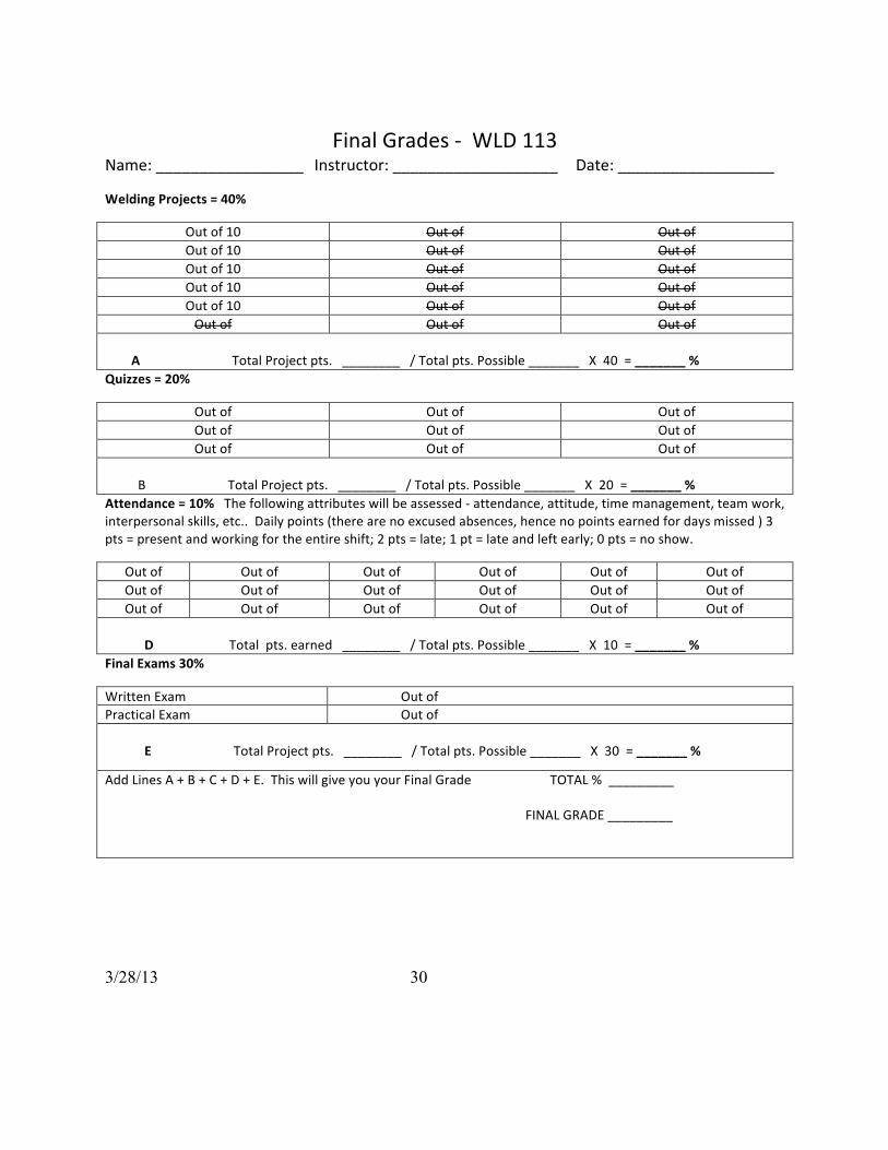
Final Grades -‐ WLD 113 Name: _________________ Instructor: ___________________ Date: __________________
Welding Projects = 40%
Out of 10 Out of Out of Out of 10 Out of Out of Out of 10 Out of Out of Out of 10 Out of Out of Out of 10 Out of Out of Out of Out of Out of
A Total Project pts. ________ / Total pts. Possible _______ X 40 = _______ % Quizzes = 20%
Out of Out of Out of Out of Out of Out of Out of Out of Out of
B Total Project pts. ________ / Total pts. Possible _______ X 20 = _______ % Attendance = 10% The following attributes will be assessed -‐ attendance, attitude, time management, team work, interpersonal skills, etc.. Daily points (there are no excused absences, hence no points earned for days missed ) 3 pts = present and working for the entire shift; 2 pts = late; 1 pt = late and left early; 0 pts = no show.
Out of Out of Out of Out of Out of Out of Out of Out of Out of Out of Out of Out of Out of Out of Out of Out of Out of Out of
D Total pts. earned ________ / Total pts. Possible _______ X 10 = _______ % Final Exams 30%
Written Exam Out of Practical Exam Out of E Total Project pts. ________ / Total pts. Possible _______ X 30 = _______ %
Add Lines A + B + C + D + E. This will give you your Final Grade TOTAL % _________ FINAL GRADE _________


