Page 1
LUND UNIVERSITY
PO Box 117221 00 Lund+46 46-222 00 00
Shift catalysts in biomass generated synthesis gas
Kirm, Ilham; Brandin, Jan; Sanati, Mehri
Published in:Topics in Catalysis
DOI:10.1007/s11244-007-0236-5
Published: 2007-01-01
Link to publication
Citation for published version (APA):Kirm, I., Brandin, J., & Sanati, M. (2007). Shift catalysts in biomass generated synthesis gas. Topics in Catalysis,45(1-4), 31-37. DOI: 10.1007/s11244-007-0236-5
General rightsCopyright and moral rights for the publications made accessible in the public portal are retained by the authorsand/or other copyright owners and it is a condition of accessing publications that users recognise and abide by thelegal requirements associated with these rights.
• Users may download and print one copy of any publication from the public portal for the purpose of privatestudy or research. • You may not further distribute the material or use it for any profit-making activity or commercial gain • You may freely distribute the URL identifying the publication in the public portalTake down policyIf you believe that this document breaches copyright please contact us providing details, and we will removeaccess to the work immediately and investigate your claim.
Page 2
Download date: 30. May. 2018
Page 3
Shift catalysts in biomass generated synthesis gas
Ilham Kirm, Jan Brandin, and Mehri Sanati This is the authors manuscript, published in compliance with the Springer Verlag copyright
agreement for parallel publication
Full Paper:
Topics in Catalysis Vol. 45, Nos. 1–4, August 2007 31
DOI: 10.1007/s11244-007-0236-5
Page 4
2
Shift catalysts in biomass generated synthesis gas Ilham Kirm
a, Jan Brandin
b, and Mehri Sanatia,
a
aSchool of Technology and Design, Växjö University, Växjö, SE-351 95 Sweden
bCatator AB, Ideon Research Park, Lund, Sweden
Abstract
One of the CHRISGAS project objectives is to study the shift catalysts in biomass-generated
synthesis gas. The water gas shift reaction is ruled by equilibrium, and the state of the gas can
for a given H2/CO ratio be shifted by addition/removal of water, CO2 and/or by a change in
the temperature. Stability area in respect to gas composition, sulphur content, pressure and
temperature for FeCr shift catalyst has been investigated by thermodynamic equilibrium
calculations. The calculations show that carbide formation is favourable in the ‘‘Normal
water’’ case without sulphur in the gas. If sulphur is present in the gas, the situation improves
due to sulphide formation.
KEY WORDS: water-gas shift; iron-chromium catalyst; carbide formation; sulphide
formation.
1. Introduction
In the search for a sustainable transport fuel, one possibility is synthetic fuels generated from
biomass. In order to use processes such as Fischer-Tropsch, methanol, DME and the Mobile
process, one needs to produce synthesis gas from the biomass first. The key steps are
gasification, reforming/partial oxidation and the shift process. In the gasification step, if
oxygen is used as an oxidant, the solid biomass is converted into a solid residual (ash) and a
gas consisting mainly of CO, CO2, H2, H2O, lower hydrocarbons (CH4 and C2) and some
tars. The hydrocarbons and the tar will be converted into CO, CO2 and hydrogen in the
reformer/partial oxidation step. When the gas leaves the reformer/partial oxidation step the
H2/CO ratio will be close to 1 [1]. To utilize the synthesis gas in the subsequent synthesis
steps, the H2/CO ratio has to be tuned to the optimum value for the process in question. This
is done in the shift step. The water gas shift reaction (1)
CO+ H2O H2 + CO2 (1)
is ruled by an equilibrium, and the state of the gas can, for a given H2/CO ratio be shifted by
addition/removal of water, CO2 and/or by a change in the temperature. In this study the
stability area in respect to gas composition, sulphur content, pressure and temperature for
FeCr shift catalyst will be investigated by thermodynamic equilibrium calculations.
2. CHRISGAS project and Värnamo pilot plant
The CHRISGAS project is sponsored by the EU and the Swedish Energy Agency (STEM)
and has as an objective to demonstrate large-scale production (3500 Nm3/h) of synthesis gas
from biomass by 2009. The project consists of two parts; CHRISGAS concerning R&D work
on various parts of the process and a second part concerning the rebuilding of the IGCC plant
located at the Växjö -Värnamo Biomass Gasification Centre in Sweden [2]. According to the
time schedule the plant should be ready for the first test runs in 2009. After rebuilding, the
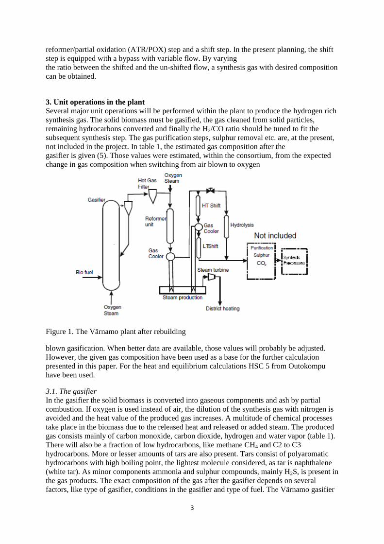
plant (figure 1) will have been changed from air to oxygen-steam-blown. A hot gas filter will
purify the gas from dust. Oxygen and steam will be added to the gas before the reformer unit
where residual hydrocarbons and tar are converted. The H2/CO -ratio will be shifted in a HT
shift reactor. If the gas requires shifting to low H2/CO value (for instance H2-production) the
unit will also contain a LT shift reactor. The plant will be equipped with an autothermal
Page 5
3
reformer/partial oxidation (ATR/POX) step and a shift step. In the present planning, the shift
step is equipped with a bypass with variable flow. By varying
the ratio between the shifted and the un-shifted flow, a synthesis gas with desired composition
can be obtained.
3. Unit operations in the plant
Several major unit operations will be performed within the plant to produce the hydrogen rich
synthesis gas. The solid biomass must be gasified, the gas cleaned from solid particles,
remaining hydrocarbons converted and finally the H2/CO ratio should be tuned to fit the
subsequent synthesis step. The gas purification steps, sulphur removal etc. are, at the present,
not included in the project. In table 1, the estimated gas composition after the
gasifier is given (5). Those values were estimated, within the consortium, from the expected
change in gas composition when switching from air blown to oxygen
Figure 1. The Värnamo plant after rebuilding
blown gasification. When better data are available, those values will probably be adjusted.
However, the given gas composition have been used as a base for the further calculation
presented in this paper. For the heat and equilibrium calculations HSC 5 from Outokompu
have been used.
3.1. The gasifier
In the gasifier the solid biomass is converted into gaseous components and ash by partial
combustion. If oxygen is used instead of air, the dilution of the synthesis gas with nitrogen is
avoided and the heat value of the produced gas increases. A multitude of chemical processes
take place in the biomass due to the released heat and released or added steam. The produced
gas consists mainly of carbon monoxide, carbon dioxide, hydrogen and water vapor (table 1).
There will also be a fraction of low hydrocarbons, like methane CH4 and C2 to C3
hydrocarbons. More or lesser amounts of tars are also present. Tars consist of polyaromatic
hydrocarbons with high boiling point, the lightest molecule considered, as tar is naphthalene
(white tar). As minor components ammonia and sulphur compounds, mainly H2S, is present in
the gas products. The exact composition of the gas after the gasifier depends on several
factors, like type of gasifier, conditions in the gasifier and type of fuel. The Värnamo gasifier
Page 6
4
is a 18 MWth circulating fluidized bed gasifier, pressurized to 10–15 bar. In table 1, the
estimated gas composition after the Värnamo gasifier is given. The low heating value (LHV)
is calculated as the heat of combustion of the given gas mixture at 25 oC, using naphthalene as
the tar component.
3.1.1. The reformer
When the gas leaves the gasifier, it contains lower hydrocarbons (methane, ethane, ethene,
etc.) and some tars (table 1). The lower hydrocarbons represent approximately 50% of the
heat content in the calculated LHV-value while the tar stands for approximately 10% of the
heat content. If the purpose of the plant is to produce synthesis gas suitable for liquid
synthetic fuel production in an economic way, the lighter hydrocarbons and the tars have to be
converted into synthesis gas as well. This is done in the reformer step by reacting the
hydrocarbons with water vapour and carbon dioxide, for instance methane:
CH4 + 2H2O CO2 + 4H2 (2)
CH4 + H2O CO + 3H2 (3)
CH4 + CO2 2CO + 2H2 (4)
All of the reactions are endothermic and heat has to be supplied to reaction vessel or the
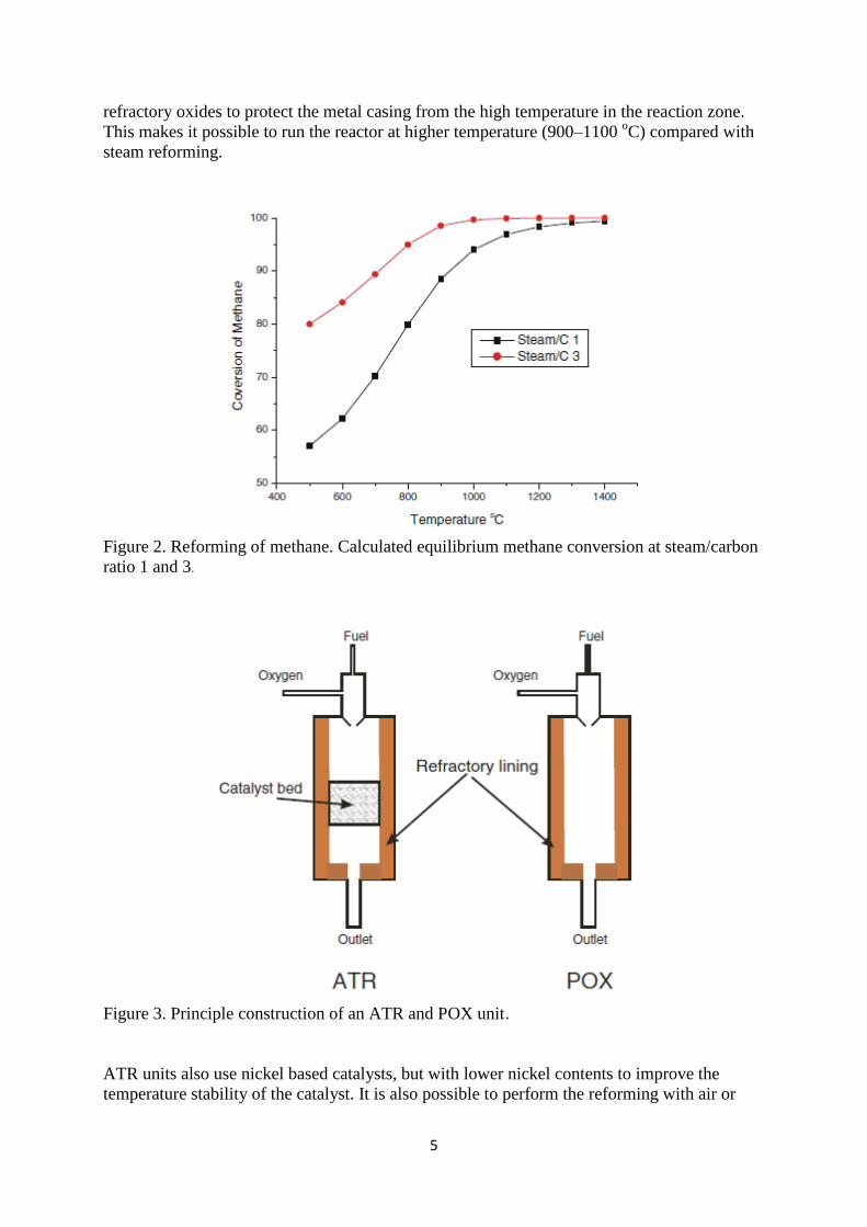
temperature will drop and the reactions will stop. Methane is the most stable hydrocarbon in
the reforming reaction because it is difficult to activate and there exist equilibrium between
methane and the synthesis gas. In figure 2 the calculated (HSC 5) equilibrium methane
conversion, at 1 bar, versus the temperature is shown at two different molar steam/carbon
ratios, 1 and 3. As can be seen in the figure 2, the lower temperature, the more water is
required to obtain full conversion of the methane. The classical reforming process is the steam
reforming, using a nickel-based catalyst, were the required heat for the reaction is supplied
externally. This means that heat have to be transferred from the outside, through the reactor
walls (multiples tube package) into the reactor. To avoid material issues, the temperature have
to be as low as possible (maximum 850 oC). This makes it necessary to use steam/carbon
ratios of about 3. It is still difficult to obtain full conversion of methane in a steam reforming
process and therefore it is often supplemented by a secondary reformer unit. The secondary
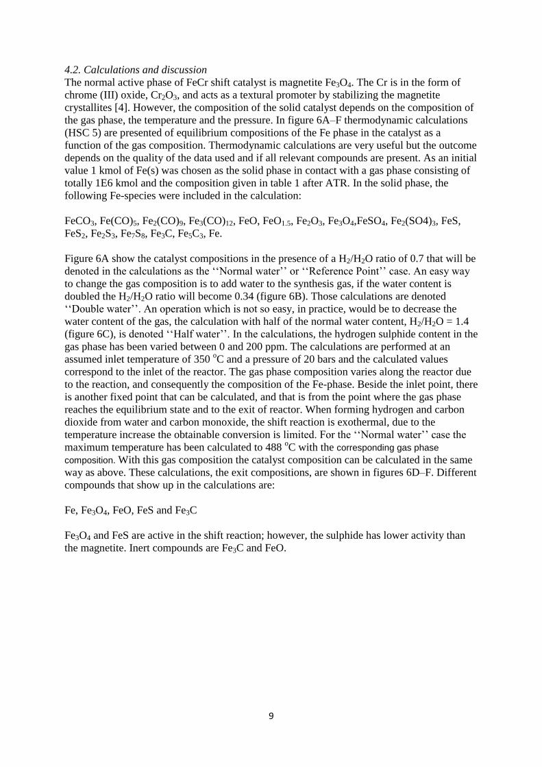
reformer unit can also be used as standalone reformer unit, autothermal reformer (ATR)
(figure 3). In such unit the required heat is generated directly in the reactor by adding air or
oxygen to the fuel and partly burns it. The reactor is lined with one or several layers of
Page 7
5
refractory oxides to protect the metal casing from the high temperature in the reaction zone.
This makes it possible to run the reactor at higher temperature (900–1100 oC) compared with
steam reforming.
Figure 2. Reforming of methane. Calculated equilibrium methane conversion at steam/carbon
ratio 1 and 3.
Figure 3. Principle construction of an ATR and POX unit.
ATR units also use nickel based catalysts, but with lower nickel contents to improve the
temperature stability of the catalyst. It is also possible to perform the reforming with air or
Page 8
6
oxygen addition homogenously in the gas phase, partial oxidation (POX), without solid
catalyst in a unit very similar to the ATR unit (figure 3). Due to the lack of catalyst POX
requires yet higher temperature than ATR to work, 1200–1400 oC. In table 1 the outcome by
using ATR and POX has been calculated by the use of HSC 5. Incoming gas by the
composition given after the gasifier has been used assuming 15 bars pressure and 800 oC in
the inlet gas stream. It is assumed that the equilibrium is reached in the reactor and there are
no heat losses. The added oxygen is provided as an equimolar O2/steam stream at 800 oC. The
C2-hydrocarbon is assumed to be ethylene and the tars naphthalene, the ammonia and
hydrogen sulphide are not participating in the calculation. The calculation was performed
iteratively, for given oxygen/steam addition the gas phase composition was calculated as
function of temperature, and then a temperature was assumed. The gas phase composition
corresponding to the assumed temperature was then put into the heat balance calculation and
the outgoing temperature was solved. This was repeated until the assumed and the calculated
temperature differed less than 10 oC. Because of the injection of the O2/H2O mixture, the mass
flow will increase (table 1). Due to the mass flow increase the LHV of the gas leaving the
gasifier is not comparable with the LHV calculated after ATR and POX on weight or volume
basis. By multiplying the calculated LHV (weight based) with the mass flow ratio between the
gas before and after the O2/H2O injection, a comparable value is obtained. Since the O2/H2O
stream is injected as 800 oC hot gas instead of oxygen and liquid water at 25
oC, it also
represents a stream of supplied heat (table 1). The efficiency value in table 1 shows the
fraction of chemically bounded heat in the gas still remaining after the unit operation.
3.1.2. The shift
When the gas leaves the reformer unit, the ratio between H2 and CO is close to 1 (table 1). To
use the produced gas in subsequent synthesis processes, for instance Fischer-Tropsch, the
ratio should be close to 2. The role of the shift steps [3,4] is to tune the ratio between H2 and
CO to the desired value according to the water gas shift reaction [5]. This reaction is ruled by
equilibrium (figure 4). The equilibrium position can be changed by a change in temperature
and/or a change in the concentrations of one or more of the components, for instance by
addition of water. However, to convert the majority of the CO into CO2 (for maximum
hydrogen production) low temperature is required. Traditionally this process is performed in
one High Temperature (HT) step and one subsequent Low Temperature (LT) step with a
cooling step in between (figure 3). The reaction is only mildly exothermic and is usually
carried out in adiabatic reactors.
Page 9
7
Figure 4. Calculated WGS equilibrium composition as function of temperature. Inlet gas
composition given in table 1 (after ATR)
3.2. High temperature shift step
The high temperature shift step using FeCr catalyst was introduced by BASF in 1915. It’s
essentially the same process and catalyst used today [3,4]. The catalyst consists of magnetite
Fe3O4 in its activated form and Cr2O3 that acts as a promoter, stabilizing the magnetite
crystals. The catalyst is resistant towards sulfur in that sense that the iron is converted into
FeS. The FeS also acts as a shift catalyst but with reduced activity, and using more catalyst
can compensate for this decrease.
3.2.1. Low temperature shift step, Cu/ZnO catalyst
The classical low temperature shift catalyst is the Cu/ZnO [3,4]. It exhibits high activity in the
shift reaction at approximately 200 oC. The use of the catalyst is limited downwards in
temperature by the dew point of the gas and upwards in temperature by sintering of the
copper, above 260 oC. The catalyst requires almost sulphur free environment since both the
Cu and the ZnO forms inactive sulphides.
3.2.2. Low temperature shift step, CoMo catalyst
When Cu/ZnO cannot be used because of high sulphur content, the sulphur resistant CoMo
catalyst can be chosen [3,4]. This catalyst actually requires sulphur in the feed because it is
active in the sulphidized form. The catalyst can also be used as a HT shift catalyst, but the
higher the temperature, the higher the sulphur content is required in the gas to keep the
catalyst in the sulphidized state. The low temperature limit is set by the dew point of the gas.
3.3. Hydrolysis step
Organic sulphur in the fuel will be converted into, predominately, hydrogen sulphide (H2S) in
the gasifier. This sulphur needs to be removed prior to the fuel synthesis steps, this is done by
an absorption step, for instance by ZnO or by scrubbing in an amine solution. However, a part
of the sulphur will be in the form of carbonyl sulphide COS. In this form the sulphur will not
be removed by the absorption step.
Page 10
8
Figure 5. Planned shift steps in the Värnamo plant. Normally the COS is converted by the
FeCr catalyst into H2S by a hydrolysis reaction (5) [3]:
COS + H2O CO2 + H2S (5)
In the Värnamo plant the H2/CO-ratio should be tuneable. This could be done by controlling
the reactor temperatures and for instance by controlled water addition. However, operating the
shift step in a flexible mode is more complex and slower than operating it in a constant mode.
Therefore, the H2/CO-ration tuning is planned to be performed by a controlled bypass flow
(figure 5). This means that the bypass flow will not be treated by the FeCr catalyst and the
total gas flow after mixing with the shifted gas will contain COS. Therefore it is necessary to
add a hydrolysis step to the bypass flow. The catalyst for this reaction is activated alumina
and the reactor should be kept 40–50 oC above the dew point.
4. Research activity
Except for the main components, the produced synthesis gas also contains minor components
like hydrogen sulphide, dust, aerosols and volatile metals that might decrease or destroy the
performance of a catalyst. Although the problems are expected to be much less in the shift
step than in the reformer step there are some matters that will have to be investigated. In the
first part of 2006 a micro reactor system will be taken into operation at Växjö University to
enable studies of the shift reaction up to 20 bars, using FeCr catalyst.
4.1. Stability of catalysts
The bio-mass generated synthesis gas contains up to 100–150 ppm of sulphur compounds, i.e.
H2S. If the sulphur is not removed prior the shift step, the catalyst must be sulphur resistant
[2]. This rule out, for instance, copper based catalysts. Sulphide based shift catalyst, on the
other hand, requires a sufficient amount of sulphur in the feed to stay active.
Page 11
9
4.2. Calculations and discussion
The normal active phase of FeCr shift catalyst is magnetite Fe3O4. The Cr is in the form of
chrome (III) oxide, Cr2O3, and acts as a textural promoter by stabilizing the magnetite
crystallites [4]. However, the composition of the solid catalyst depends on the composition of
the gas phase, the temperature and the pressure. In figure 6A–F thermodynamic calculations
(HSC 5) are presented of equilibrium compositions of the Fe phase in the catalyst as a
function of the gas composition. Thermodynamic calculations are very useful but the outcome
depends on the quality of the data used and if all relevant compounds are present. As an initial
value 1 kmol of Fe(s) was chosen as the solid phase in contact with a gas phase consisting of
totally 1E6 kmol and the composition given in table 1 after ATR. In the solid phase, the
following Fe-species were included in the calculation:
FeCO3, Fe(CO)5, Fe2(CO)9, Fe3(CO)12, FeO, FeO1.5, Fe2O3, Fe3O4,FeSO4, Fe2(SO4)3, FeS,
FeS2, Fe2S3, Fe7S8, Fe3C, Fe5C3, Fe.
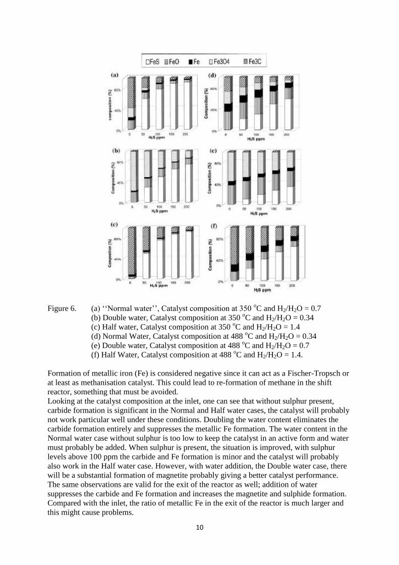
Figure 6A show the catalyst compositions in the presence of a H2/H2O ratio of 0.7 that will be
denoted in the calculations as the ‘‘Normal water’’ or ‘‘Reference Point’’ case. An easy way
to change the gas composition is to add water to the synthesis gas, if the water content is
doubled the H2/H2O ratio will become 0.34 (figure 6B). Those calculations are denoted
‘‘Double water’’. An operation which is not so easy, in practice, would be to decrease the
water content of the gas, the calculation with half of the normal water content, H2/H2O = 1.4
(figure 6C), is denoted ‘‘Half water’’. In the calculations, the hydrogen sulphide content in the
gas phase has been varied between 0 and 200 ppm. The calculations are performed at an
assumed inlet temperature of 350 oC and a pressure of 20 bars and the calculated values
correspond to the inlet of the reactor. The gas phase composition varies along the reactor due
to the reaction, and consequently the composition of the Fe-phase. Beside the inlet point, there
is another fixed point that can be calculated, and that is from the point where the gas phase
reaches the equilibrium state and to the exit of reactor. When forming hydrogen and carbon
dioxide from water and carbon monoxide, the shift reaction is exothermal, due to the
temperature increase the obtainable conversion is limited. For the ‘‘Normal water’’ case the
maximum temperature has been calculated to 488 oC with the corresponding gas phase
composition. With this gas composition the catalyst composition can be calculated in the same
way as above. These calculations, the exit compositions, are shown in figures 6D–F. Different
compounds that show up in the calculations are:
Fe, Fe3O4, FeO, FeS and Fe3C
Fe3O4 and FeS are active in the shift reaction; however, the sulphide has lower activity than
the magnetite. Inert compounds are Fe3C and FeO.
Page 12
10
Figure 6. (a) ‘‘Normal water’’, Catalyst composition at 350 oC and H2/H2O = 0.7
(b) Double water, Catalyst composition at 350 oC and H2/H2O = 0.34
(c) Half water, Catalyst composition at 350 oC and H2/H2O = 1.4
(d) Normal Water, Catalyst composition at 488 oC and H2/H2O = 0.34
(e) Double water, Catalyst composition at 488 oC and H2/H2O = 0.7
(f) Half Water, Catalyst composition at 488 oC and H2/H2O = 1.4.
Formation of metallic iron (Fe) is considered negative since it can act as a Fischer-Tropsch or
at least as methanisation catalyst. This could lead to re-formation of methane in the shift
reactor, something that must be avoided.
Looking at the catalyst composition at the inlet, one can see that without sulphur present,
carbide formation is significant in the Normal and Half water cases, the catalyst will probably
not work particular well under these conditions. Doubling the water content eliminates the
carbide formation entirely and suppresses the metallic Fe formation. The water content in the
Normal water case without sulphur is too low to keep the catalyst in an active form and water
must probably be added. When sulphur is present, the situation is improved, with sulphur
levels above 100 ppm the carbide and Fe formation is minor and the catalyst will probably
also work in the Half water case. However, with water addition, the Double water case, there
will be a substantial formation of magnetite probably giving a better catalyst performance.
The same observations are valid for the exit of the reactor as well; addition of water
suppresses the carbide and Fe formation and increases the magnetite and sulphide formation.
Compared with the inlet, the ratio of metallic Fe in the exit of the reactor is much larger and
this might cause problems.
Page 13
11
5. Undesired reactions
With increased pressure, there are risks for undesirable reaction paths, for instance
methanisation and Fisher-Tropsch reactions. This will be the case if metallic iron is formed,
and the reaction condition must be chosen to avoid the risks for such unselective operation of
the catalytic reactor. In the best case an unselective operation might counteract the reformer
and produce new hydrocarbons from the synthesis gas. In the worst case the presence of a
more exothermal reaction than the shift reaction could cause a thermal runaway.
6. Conclusions
The calculations show that carbide formation is favourable in the ‘‘Normal water’’ case
without sulphur in the gas. If sulphur is present in the gas, the situation improves due to
sulphide formation. However, increased water content, double water case, shows increased
magnetite formation and suppression of carbide and elementary iron. The water content in the
Normal water case is probably too low. Addition of water will probably improve the
performance substantially decrease the re-formation of hydrocarbon, i.e. methane, in the HT
shift step.
Acknowledgments
The financial support of the EU Commissions’ CHRISGAS FP 6 Project (contract number:
SES6-CT-2004-502587) and the Swedish Energy Agency is gratefully acknowledged.
References
[1] D.L. Trimm, App. Catal. A Gen. 296 (2005) 1.
[2] P. Hou, D. Meeker and H. Wise, J. Catal. 80 (1983) 280.
[3] G. Ertl, H. Kno¨ tzinger and J. Weitkamp (eds) Handbook of Heterogeneous Catalysis,
vol. 4, p. 1811 (1997) VCH, Weinheim,Germany. ISBN 3-527-29212-8.
[4] M.W. Twigg, Catalyst Handbook, 2nd edn, p. 283 (1996) Manson publishing ltd. ISBN 1-
874545-36-7.
[5] S. Albertazzi, F. Basile, J. Brandin, J. Einvall, C. Hulteberg, G.Fornasari, V. Rosetti, M.
Sanati, F. Trifiro` and A Vaccari, Catal. Today 106 (2005) 297.