shiftIO: Reconfigurable Tactile Elements for Dynamic Affordances and Mobile Interaction Evan Strasnick 1 Jackie Yang 1 Kesler Tanner 1 Alex Olwal 2 Sean Follmer 1 1 Stanford University, Stanford, CA, USA 2 Google, Inc., Mountain View, CA, USA; {estrasni, jackiey, keslert, sfollmer}@stanford.edu, [email protected]Figure 1: Reconfigurable tactile elements (shown in arrows) for interaction on a mobile device. Left to right: a flexible PCB utilizing micro-coils for magnetic actuation of tactile elements, a mobile prototype using the PCB micro-coil technique, a mobile prototype using low-power switchable permanent magnet actuation, a game played using reconfigurable tactile controls, a wearable band with tactile elements for display and interaction. ABSTRACT Currently, virtual (i.e. touchscreen) controls are dynamic, but lack the advantageous tactile feedback of physical controls. Similarly, devices may also have dedicated physical controls, but they lack the flexibility to adapt for different contexts and applications. On mobile and wearable devices in particular, space constraints further limit our input and output capabilities. We propose utilizing reconfigurable tactile elements around the edge of a mobile device to enable dynamic physical con- trols and feedback. These tactile elements can be used for physical touch input and output, and can reposition according to the application both around the edge of and hidden within the device. We present shiftIO, two implementations of such a system which actuate physical controls around the edge of a mobile device using magnetic locomotion. One version uti- lizes PCB-manufactured electromagnetic coils, and the other uses switchable permanent magnets. We perform a technical evaluation of these prototypes and compare their advantages in various applications. Finally, we demonstrate several mobile applications which leverage shiftIO to create novel mobile interactions. Permission to make digital or hard copies of all or part of this work for personal or classroom use is granted without fee provided that copies are not made or distributed for profit or commercial advantage and that copies bear this notice and the full citation on the first page. Copyrights for components of this work owned by others than the author(s) must be honored. Abstracting with credit is permitted. To copy otherwise, or republish, to post on servers or to redistribute to lists, requires prior specific permission and/or a fee. Request permissions from [email protected]. CHI ’17, May 06 - 11, 2017, Denver, CO, USA Copyright is held by the owner/author(s). Publication rights licensed to ACM. ACM 978-1-4503-4655-9/17/05...$15.00 DOI: http://dx.doi.org/10.1145/3025453.3025988 ACM Classification Keywords H.5.2. User Interfaces: Graphical user interfaces (GUI), Hap- tic I/O, Input devices and strategies Author Keywords Mobile Haptics; Tactile Display; Dynamic Affordance; Magnetically-actuated Buttons INTRODUCTION Current mobile devices allow users to choose from millions of applications. However, due to the convergence of hardware for smartphones and tablets, interaction with these different applications is generally limited to the same means of physical input—a touch screen and a few physical buttons. This greatly limits interaction, especially when the user cannot visually attend to the display, which is a common scenario when users multi-task in a mobile context, but also an everyday reality for the visually impaired. Thus, we seek to expand the capabilities of mobile I/O without radically changing the form factor or functionality of these devices. In particular we asked ourselves: What if the physical interface elements of a mobile device could reconfigure on the device to fit the application and user needs? In this paper, we propose a new approach to mobile physi- cal interaction: reconfigurable tactile elements (RTEs) which can travel on the exterior of traditional mobile and wearable devices. We specifically explore RTEs on the edges of mo- bile devices, resulting in shiftIO, a smartphone prototype with dynamic physical controls which can emerge from a hidden reservoir, move to a target location along its edge, and re- turn to a hidden state. These RTEs can both provide haptic
Transcript
shiftIO: Reconfigurable Tactile Elements for DynamicAffordances and Mobile Interaction
Evan Strasnick1 Jackie Yang1 Kesler Tanner1 Alex Olwal2 Sean Follmer1
1Stanford University, Stanford, CA, USA 2Google, Inc., Mountain View, CA, USA;estrasni, jackiey, keslert, [email protected], [email protected]
Figure 1: Reconfigurable tactile elements (shown in arrows) for interaction on a mobile device. Left to right: a flexible PCButilizing micro-coils for magnetic actuation of tactile elements, a mobile prototype using the PCB micro-coil technique, a mobileprototype using low-power switchable permanent magnet actuation, a game played using reconfigurable tactile controls, a wearableband with tactile elements for display and interaction.
ABSTRACTCurrently, virtual (i.e. touchscreen) controls are dynamic, butlack the advantageous tactile feedback of physical controls.Similarly, devices may also have dedicated physical controls,but they lack the flexibility to adapt for different contexts andapplications. On mobile and wearable devices in particular,space constraints further limit our input and output capabilities.We propose utilizing reconfigurable tactile elements aroundthe edge of a mobile device to enable dynamic physical con-trols and feedback. These tactile elements can be used forphysical touch input and output, and can reposition accordingto the application both around the edge of and hidden withinthe device. We present shiftIO, two implementations of sucha system which actuate physical controls around the edge ofa mobile device using magnetic locomotion. One version uti-lizes PCB-manufactured electromagnetic coils, and the otheruses switchable permanent magnets. We perform a technicalevaluation of these prototypes and compare their advantages invarious applications. Finally, we demonstrate several mobileapplications which leverage shiftIO to create novel mobileinteractions.
Permission to make digital or hard copies of all or part of this work for personal orclassroom use is granted without fee provided that copies are not made or distributedfor profit or commercial advantage and that copies bear this notice and the full citationon the first page. Copyrights for components of this work owned by others than theauthor(s) must be honored. Abstracting with credit is permitted. To copy otherwise, orrepublish, to post on servers or to redistribute to lists, requires prior specific permissionand/or a fee. Request permissions from [email protected] ’17, May 06 - 11, 2017, Denver, CO, USACopyright is held by the owner/author(s). Publication rights licensed to ACM.ACM 978-1-4503-4655-9/17/05...$15.00DOI: http://dx.doi.org/10.1145/3025453.3025988
ACM Classification KeywordsH.5.2. User Interfaces: Graphical user interfaces (GUI), Hap-tic I/O, Input devices and strategies
INTRODUCTIONCurrent mobile devices allow users to choose from millionsof applications. However, due to the convergence of hardwarefor smartphones and tablets, interaction with these differentapplications is generally limited to the same means of physicalinput—a touch screen and a few physical buttons. This greatlylimits interaction, especially when the user cannot visuallyattend to the display, which is a common scenario when usersmulti-task in a mobile context, but also an everyday reality forthe visually impaired. Thus, we seek to expand the capabilitiesof mobile I/O without radically changing the form factor orfunctionality of these devices. In particular we asked ourselves:What if the physical interface elements of a mobile devicecould reconfigure on the device to fit the application and userneeds?
In this paper, we propose a new approach to mobile physi-cal interaction: reconfigurable tactile elements (RTEs) whichcan travel on the exterior of traditional mobile and wearabledevices. We specifically explore RTEs on the edges of mo-bile devices, resulting in shiftIO, a smartphone prototype withdynamic physical controls which can emerge from a hiddenreservoir, move to a target location along its edge, and re-turn to a hidden state. These RTEs can both provide haptic
feedback and enable expressive input methods utilizing thedominant or non-dominant hand. As discrete, movable tactileelements, RTEs permit a number of interactions on a mobileinterface, such as shear input and tactile display. They enablecontext-dependent physical controls for applications, and in-troduce new tactile notifications that allow a user to “glance”at information through touch. Because these RTEs operate onthe edges of the device, users can interact with them withoutoccluding the graphical display.
In selecting an implementation to realize the tactile elements,we chose to explore magnetic actuation with the goal of asmall, lightweight, low cost design with few moving partswhich could be integrated into mobile devices (phones andtablets), wearables (e.g. smart watches), and automobile dash-board interfaces or steering wheels. Magnetic actuation utiliz-ing an array of electromagnetic coils and passive RTEs alsoenables the system to scale towards a high number of elements,in contrast to mechanical actuation methods. This paper exam-ines the strengths and weaknesses of two different magneticactuation techniques and the prototypes built to explore them.The first utilizes thin electromagnetic micro-coils integratedinto flexible printed circuit boards, inspired by previous work[7, 27, 28]. These boards can be designed and fabricated withtraditional Printed Circuit Board (PCB) techniques, making itideal for applications requiring thin form factors and low cost.The second system uses a bi-stable design through switchablepermanent magnets, which have a larger footprint and aremore rigid, but potentially result in significantly lower powerconsumption. These systems have been integrated into twoform factors. The first positions RTEs on the edges of a mobiledevice, the second utilizes the thin form factor of the FlexibleMicro Coil system to be integrated into a wearable wristband.
Contributions• The concept of Reconfigurable Tactile Element Interfaces
to enable dynamic affordances and haptic feedback on thephysical surfaces of devices.
• shiftIO - Two mobile implementations of such an interfacewhich leverage the electromagnetic actuation of neodymiumelements:
– Flexible Micro-Coil System based on thin, flexible PCBwith micro-coils for arbitrarily curved surfaces andminimal footprint in small devices.
– Switchable Permanent Magnet System that enables bi-stability and low power magnetic actuation.
• A technical evaluation of the electrical characteristics andmagnetic properties of shiftIO, discussing their suitabilityfor mobile hardware.
• Novel applications and mobile interaction techniques fora Reconfigurable Tactile Element Interface that enablecontext-specific controls, self-adjusting interface elements,physical extensions of the GUI, and rich haptic notifications.
RELATED WORK
Mobile Tactile InteractionMuch research attention has focused on expanding the physi-cal output modalities of mobile devices. In addition to actuat-ing the entire device through vibration, there are broadly twoclasses of approach: 1) systems that provide surface hapticsco-located directly on a touch screen display, and 2) tactilefeedback on the periphery (e.g. edge or back) of the device.Haptic feedback can be added directly to GUI interactionsthrough vibration [29, 5, 21], electrostatic friction [2] or re-configurable elements emerging from the display (e.g. bypneumatics [11], hydraulics [8], or actuation [10, 30]).
Other contributions have utilized the periphery of mobiledevices, exploring touch on the back [3], sides [4, 13] andsurrounding regions [6]. Mobile devices also often includepassive physical controls near the edges, and one line of re-search involves increasing the dynamic nature of these ele-ments. Hemmert et al. created a single dynamic button formobile interactions [12], and Pasquero et al. created a buttonwith an array of piezo actuators to provide skin stretch directlyto the user’s thumb [24]. More recently, Jang et al. augmenteda mobile device with an array of linear actuators to createdynamic affordances. [16].
Also related is the Eone Bradley tactile watch [34]. This watchuses two magnetic ball bearings in grooves to display thetime both visually and tactually. This system has no inputcapabilities, and is limited to two tactors on different surfacesdue to its use of a motorized actuation system.
While mobile tactile feedback as a whole has received muchresearch attention, we believe that RTE Interfaces have a num-ber of key distinctions from prior work, such as the ability tosupport lateral displacement for feedback and user input.
Reconfigurable and Actuated Input DevicesResearchers have also explored user reconfigurable physical in-put devices. Some work, such as that of Jansen and colleagues,customizes a traditional device with passive physical widgetsthat can be sensed for input [17, 38]. Villar and Gellersenused pushpin-style connectors and flexible circuit membranes[35]. In the mobile space, the MagGetz system used magneticsensing to allow users to reposition physical input elementswhich were sensed by a mobile device’s magnetometer [14].These systems require the user to manually reconfigure thedevice, which makes them low-cost.
Outside of a mobile context, there has been much work in cre-ating actuated table top interfaces with reconfigurable tangibleelements [1, 20, 23, 26, 31]. Researchers have also exploredhow users perceive these moving physical affordances by lever-aging patterns of motion and shape change [33]. Many of thesesystems use arrays of electromagnets to induce magnetic fieldsand move permanent magnets [23, 25, 36, 37]. However, suchsystems require large electromagnets, making them ill-suitedto mobile applications. To address the size and power con-straints of mobile devices, we require an alternative design.Furthermore, our system must work in various orientations andconfigurations. Our goal is to reduce the cost, size, and power
consumption of such a system, and to develop meaningfulinteractions to work in the mobile context.
Magnetic LocomotionSince at least the 1990s, researchers have been exploring mag-netically levitated and controlled micro robots for manufac-turing [9, 27]. These devices are fabricated using traditionalPCB techniques [28] and utilize diamagnetic materials to lev-itate the magnets to reduce friction. Many of these systemsuse a row and column approach to drive the magnetic field.However, this presents challenges for independent control ofmultiple robots, leading to the exploration of alternative ap-proaches [7, 18]. Inspired by this work, we aim to apply asimilar technology to mobile user interfaces, with the addi-tional challenges posed by interaction and display, such as theneed for integrated sensing.
RECONFIGURABLE TACTILE ELEMENTSWe propose a new class of I/O for providing dynamic physi-cal affordances on mobile devices called the ReconfigurableTactile Element Interface. In these interfaces the physical ele-ments can reconfigure their positions on a device to adapt todifferent applications or provide haptic feedback. While theseelements can be perceived visually, their main function is intactile interaction, and thus we chose not to explore integratedvisual display elements such as LEDs.
Design SpaceThere are a number of parameters to be considered whendesigning a RTE Interface. These parameters affect the waysin which RTEs are used for display and interaction, as wellas the size and power consumption of its components. Weexplore this design space in the section below.
Size. The size of a RTE changes how the user interacts with itmuch like a static button. Fitt’s Law and ergonomic guidelinesshould be used to determine the ideal size. Smaller elementscould be combined to form larger compound elements.
Number. The number of elements supported by the systemhas a large impact on its interactions and applications. Asingle RTE enables simple interactions with a single interfaceelement, such as a scroll bar. With more RTEs, more complexinterfaces can be generated, and more expressive tactile displaycan be achieved. Multiple elements could be attached togetherto form larger elements, and then split apart.
Dimensionality. This paper focuses on 1D actuation. However,RTEs could operate in 2D on a given surface, or stack to createelements of different heights.
Location. The RTEs can be located on different areas of aninteractive device. RTEs could be located on the 2D visualdisplay of a device, or on the back of the device. Here weexplore interaction on the edges of the device.
Homogeneous vs. Heterogeneous. RTEs can all be the sameshape and size, or they could be comprised of a set of differinggeometries. For example, a larger button could be used asa camera shutter, whereas smaller buttons could form zoomcontrols. This could also enable the use of Phicons [15].
Visibility and Accessibility. RTEs could be exposed at alltimes. Alternatively, RTEs could be stored out of sight of theuser in a reservoir. Because they are physical elements andcannot instantaneously appear/disappear, it is important to helpthe user to distinguish when the RTE is actively displayinginformation and when it is moving into a position.
Force. The amount of force a RTE can impart largely affects itsuse in feedback. Low force suggests that it can mostly be usedfor locomotion of the RTE. However, a RTE with higher forcecould impart force on a user and induce a haptic sensation,either by hitting the side of their finger, vibrating underneathit, or even moving the finger.
User Input. RTEs can be touch sensitive, either by integratingsensing into the RTE or elsewhere in the device. This touchcould also be pressure sensitive to provide analog input. If theRTEs are backdriveable or loosely coupled to the actuation(i.e. through magnetic fields), it is possible for the user toreposition the RTE. In this mode, the RTE can be used forshear input through its lateral displacement, provided thatthere is appropriate position sensing.
InteractionThe RTE Interface consists of a number of passive RTEs thatcan be actuated to assume different positions and roles aroundthe edge of a device. These elements can, for example, actas physical controls, haptic notifications, or tactile displays.They can emerge from a hidden state within the device itself,assume a given function on the device, and then return backinto concealment when the interaction completes. Multipleelements can be actuated at once.
RTEs can be interacted with in a static state, wherein theyassume a particular form when an application is launched andact like traditional physical controls. Alternatively, RTEs canuse their ability to dynamically reposition to provide moreactive affordances. For example, a button moving quickly inan erratic pattern might imply that users should not touch it.
These RTEs can be controlled in coordination with the primarygraphical display of the device. As such, there are differentparadigms by which to design these joint interactions: Bymirroring, RTEs can display the same interface elements asdisplayed on the graphical display, such as physical buttonsnear existing virtual buttons. By complementing, RTEs candisplay a spatially relevant interface element in addition tothe graphical display, such as a scroll bar for text. Finally, byextending, RTEs can render information not represented onthe primary display, such as a notification.
We describe below some of the main interaction primitives ofthe RTE Interface:
• Buttons. A RTE becomes a dynamic, touch responsivebutton on the edge of the device. Because it can be locatedeasily via the sense of touch, the button is more readilyrecognized than a virtual button when attempting input.
• Sliders. A RTE acts as a linear slider, allowing the user toscroll through content by moving a physical control downthe side of the device.
• Toggles. A RTE becomes a switch, where a tap causes it totoggle the value for a parameter, and correspondingly moveto a new position that represents the updated value.
• Pinch controls. A pair of RTEs operate to form a pinch-gesture interaction with physical feedback, e.g. for zooming.Users can slide the RTEs closer together or further apart toadjust along a continuous scale.
In addition to generating these input elements, RTEs are alsocapable of providing feedback to the user through a numberof techniques:
• Haptic notifications. RTEs can be used to “bump” intothe user’s hand as it grips the device, alerting them of newinformation in a discreet fashion.
• Physical information display. RTEs can represent discretechunks of information, such as unread notifications or num-ber of participants in a chat room, which can be perceivedboth visually and haptically by the user. Further, motionof the RTE can also be used for information display, suchas rendering a loading bar, or a playback head for a musicplayer.
• Haptic detents in lateral interaction. The device can createregions of varying force, such that a user moving an inter-face element along the device feels haptic pulls or resistanceto their action.
SHIFTIO IMPLEMENTATION
Technical ConsiderationsThere are many actuation approaches that could be used toimplement RTE Interfaces, including belt/cable driven tac-tors, linear actuators (motor driven, S.M.A, pneumatic, hy-draulic, etc.), electrostatic actuation, magnetic actuation, orself-actuated elements (such as microrobots). We considereda number of factors in the design of shiftIO, towards the goalof creating a system suitable for mobile and wearable applica-tions:
Size. Size is a chief concern in mobile and wearable devices.Ideally, the actuation technology is thin and light, so as not toadd thickness or weight to a mobile or wearable device. Thelength of the active area and max linear displacement of RTEswas also an important consideration, as we wanted to allowfor interaction on multiple sides of the device.
Multiple Elements. Our goal was to support several elementssimultaneously. This scaling issue limits the feasible technicalsolutions, as many technologies would make it difficult todrive RTEs along a single track. For example, if linear actua-tors were used they may physically collide or not have enoughspace, unless stacked. Cable driven systems could supportmore elements, but still run into space constraints. Magneticdrive systems could theoretically support many RTEs simulta-neously, based on the number of magnetic coils present.
Force. The force of the RTEs is important both for hapticfeedback and for the robustness of the system. Stronger lat-eral forces allow us to create greater haptic sensations, and astronger normal force helps to keep the RTE from dislodging
from its target position. The amount of force varies greatlywith the chosen actuation mechanism. For example, largeforces are most easily achieved via motor-driven systems.
Cost. The cost per RTE is also a consideration. Small motorsand linear actuators generally have relatively high parts costs,so it is rare to find multiple of them in one consumer product.Often, components that can be easily fabricated with existingPCB technology can be low cost, due to the optimization andscale of this fabrication process.
Reduced number of moving parts. Lowering the number ofmoving parts that can be broken by users or external forces isa key consideration. Many linear actuators are not compliantor backdrivable, which would cause them to potentially break.Magnetic action provides compliance and robustness to highforces, as the RTE can just slide freely if a high external forceexceeds the magnetic force.
Power Consumption. Power consumption for mobile devicesis extremely important. Some technologies only use power tomove elements (most linear actuators, switchable magnets),however others require power to hold a steady state (e.g. shape-memory alloys and electromagnets).
Implementation Design SelectionPrioritizing the goal of independently controlling a numberof RTEs along the edges of a mobile device or wearable, wedecided to utilize a magnetic approach to actuation, as opposedto mechanical alternatives such as linear actuators or beltsbeneath the edge of the device. We chose to explore twodifferent approaches to magnetic actuation - thin and flexibleelements that could be low cost to produce, and secondly,lower power consumption using switchable magnets. Both ofthese systems share a number of benefits including the reducednumber of moving parts and overall low cost to actuate manyRTEs, with the trade-off of a relatively low output force. Bothversions of shiftIO provide enough force to allow for hapticfeedback in the form of “taps” on the side of the finger, butnot enough to physically displace the user’s finger.
In the sections that follow, we refer to our specific implementa-tions of a RTE Interface (shiftIO), noting that other implemen-tations could facilitate somewhat different interactions andapplications.
FLEXIBLE MICRO COIL SYSTEMIn the first version of shiftIO, the RTEs are actuated by aflexible multilayer PCB with patterned copper traces. To drivemagnetic elements, we require only a thin, flexible strip ofsmall coils, which can be manufactured through standard PCBfabrication techniques. Further, a single strip can be foldedaround to cover the entire perimeter of the device, simplifyingthe transition between edges. By continuing this strip beyondthe exposed area, we create a reservoir area where RTEs canbe stored in a “hidden” state when unused.
Running current through the circuit layers creates magneticfields and imparts forces on the RTEs, causing the RTEs tomove in a controlled direction. In addition to the lateral move-ment, the effect also creates a strong normal force which keepsthe RTEs attached to the circuit surface even when vertical.
10 mm
Figure 2: Interleaved micro-coils on a flexible PCB. Top: Thetotal length of the PCB is 27 cm, allowing it to operate onall sides of a mobile device. Bottom: Close up of coils andtransistors. Coils have a radius of 2.5 mm. Each transistorcontrols a single coil.
Each layer of the PCB contains a series of micro-coils (seeFigure 2). The circuit layers are patterned identically, butare offset so that as the layers are driven independently, themagnets are pushed and pulled to the next position. The RTEsare driven in open-loop control via microstepping—i.e. the ac-tivation of a given coil is increased and decreased by adjustingPWM pulse widths.
In similar systems such as [7], a combination of repulsive andattractive forces have been used to create smooth motion ofthe travelling magnet. However, creating both attractive andrepulsive forces from the same set of coils requires switchingwith an H-bridge configuration for each coil, drastically in-creasing the cost, complexity, and size of the circuitry. Instead,by solely leveraging attractive forces, we can switch each coilwith a single transistor. The differences in drive patterns in
Figure 3: Single-transistor drive versus H-Bridge drive forour interleaved micro-coil setup. With a single transistor, amicrostep involves transferring power from one coil to thenext, shifting the attractive force. With an H-bridge, coilsbeneath the RTE produce an attractive force (red), while coilsbordering the RTE produce a repelling force (blue).
Figure 4: A mechanical track constrains the motion of theRTE, while exposing one end for user interaction.
the single transistor and H-bridge configurations are shown inFigure 3.
While a normal force is generated in the drive process to keepthe RTE atop the PCB coils, we additionally mechanicallyconstrain the motion of the RTE by fixing it to travel within afixed track along the side of the device (as shown in Figure 4).The magnetic base of the RTE slides along the coils beneaththe track, and a 3D-printed cap on the magnet protrudes as aregion for user interaction. This keeps the RTE from escapingeven when powered off, and helps prevent dislodging in theevent of bumps or drops.
Coil DesignThe first consideration in designing the PCB is the layout andnumber of coils. By interleaving multiple sets of coils offsetin phase, we can achieve a smoother travel in either directionthan with a single set of coils of the same radius. However,assuming the same force per coil, powering additional coilsresults in increased power consumption as well as an increasednumber of transistors required over the same length. shiftIOuses two sets of coils positioned 180 degrees out of phase,which can optionally be run using just a single set.
Secondly, we consider the design of each individual coil.Based on the work of Cappelleri et al., we utilize a spiral-shaped micro-coil, to maximize the field in the region beneaththe cylindrical magnet in the planar PCB layer [7]. Our param-eters include the radius of the coil, the thickness of the trace,and the number of turns. To inform our designs, we used finiteelement analysis (FEMM [22]) to explore the effect of variousparameters on the resulting output force. We approximate ourspiral shape as a series of concentric circles for the purposesof simulation. The simulation geometry is shown in Figure 5.
Given that the traces are relatively short and contribute min-imal resistance, we can vary the trace width and assume aconstant current without much error. The results of varyingthe number of turns in tandem with trace width are shownin Figure 6. As expected, a tightly wound spiral with thintraces produces the largest force on the RTE, so our coils aredesigned with the minimum trace width/separation per themanufacturer (0.125 mm), and the maximum number of turns(10) in an empirically chosen radius (2.5 mm).
Magnet SelectionMagnet GradeshiftIO utilizes N52 Neodymium magnets as the RTE base.The N52 grade is one of the highest available, and Neodymium
Figure 5: Axisymmetric finite element analysis showing theflux density of our magnetic RTE atop a single powered 2-layer, 10-turn coil.
Figure 6: The normal force experienced by a RTE locateddirectly above a single coil powered at 1A. As the numberof turns are increased, the trace width is decreased to fill thesame 5 mm diameter radius with a constant .125mm separationbetween turns. Normal forces were calculated using blockintegral stress tensors.
magnets are particularly suitable for translations on flat circuitsgiven their high surface magnetic field.
Magnet DimensionsThe dimensions of our magnets take into consideration boththe constraints of actuation as well as the ideal form for userinteraction. While magnetic field strength increases with boththickness and diameter and enables greater attractive forces,increased dimensions also increase the weight of the RTE,which has a net decrease in performance. Thus, the idealmagnet for shiftIO has the smallest dimensions while stillbeing large enough to permit user interactions.
We settled on a 1/16" (1.59 mm) magnet thickness, and a1/8" (3.18 mm) magnet diameter. The diameter allows usto constrain the motion of the RTE within the mechanicaltrack, while affording sufficient area for touch interaction. Thethickness is sufficient to provide stability to the section of theRTE within the track, allowing it to resist torque resultingfrom the weight of the 3D-printed cap.
The mass of the magnet is 0.09 g, and the printed cap adds anextra 0.04 g, for a total of 0.13 g.
Figure 7: Exploded view of the PCB micro-coil system, con-sisting of a RTE, a linear track, flexible circuit layers contain-ing interleaved electromagnetic coils, and a soft potentiometer.
100 mm RTE
Track
Flexible PCB
PWM Chip
3D-Printed Case
Structural Support
Figure 8: shiftIO prototype using a 4-layer flexible PCB. The3D printed case has integrated tracks for the RTE to slide in.
System DesignOur final design (Figure 2) uses a four-layer flexible PCB,with one coil set in layers 1 and 3, and the other set in layers 2and 4. A via connects each of two paired coils between layersto make a continuous trace, effectively increasing the numberof turns in the same radius. The two sets are offset 180 degreesout of phase. Each coil has 10 turns in each layer, for a totalof 20 turns, equating to roughly 1Ω of resistance.
An Arduino Uno microcontroller controls the coils usingPCA9685 PWM ICs over I2C communication. Each IC iscapable of driving 16 coils, and each coil is switched with aCSD13383F4T transistor. In addition, a linear soft potentiome-ter behind the PCB is used to sense pressure and to calculatethe input position when a user pushes a button into the track.An exploded view of the layers of the system is shown inFigure 7.
Mechanical DesignTo test shiftIO with an existing mobile device, we 3D printed acase to house the electronics alongside an iPod Touch (Figure8). The case features a linear track to constrain the motionof the RTEs, and has interior room for RTEs to “disappear”when not used in a given application. We utilize a Blue-tooth Low-Energy UART module from Adafruit Industriesto communicate with the iPod Touch, enabling interactiveapplications.
We also designed a wearable form factor utilizing a wristband-style device, see Figure 9. A 3D-printed case encloses the
RTEs
Figure 9: The wristband wearable device with RTEs. Thisprototype utilizes a 3D printed case and the Flexible Micro-coil array to actuate magnetic RTEs.
device and again has an integrated a linear track. The RTEscan travel around the wrist to display information to the user.While the current prototype does not have a coordinated graph-ical display or touch sensing, those could be added as for themobile device.
Technical EvaluationThe first shiftIO prototype runs at 1.1V and draws a steady0.5 A of current per RTE, regardless of whether the RTE ismoving or stationary. RTEs can be actuated at speeds up to 80mm/s. An individual RTE can be positioned to a resolution of≈1 mm. Because of magnetic interactions between RTEs inclose proximity, a minimum separation of 15 mm is requiredbetween adjacent RTEs.
RTESwitchable Magnets
Track
Figure 10: A prototype system utilizing a switchable perma-nent magnet drive.
SWITCHABLE PERMANENT MAGNET SYSTEMIn many applications, RTEs remain in static positions for sig-nificant periods of time. In our current design, holding thisposition requires continuous power. To demonstrate an alter-nate design with greater power efficiency, we prototyped asecond version of shiftIO (Figure 10) which leverages switch-able electromagnet actuators to generate the magnetic field.We use a magnet design similar to that described by Strasnickand Follmer, with Grade 6 AlNiCo magnets wrapped in asolenoid [32]. Because of the low coercivity of the AlNiComagnet, when current is briefly pulsed through the wire, thepolarity of the magnet is permanently changed. This allows usto maintain an attractive force on the RTE without continuouspower.
We use the same N52 neodymium magnets for the RTEs.Switchable permanent magnets are lined up along the edge of
the device (Figure 10). Each AlNiCo magnet is wound withN = 140 turns of 36 AWG wire, yielding a radius of 1.9 mm.Rather than traveling directly atop the AlNiCo magnets, RTEstravel along a spacing surface. The width of this spacer (2.275mm) was chosen to be thick enough for the AlNiCo magnetsto switch easily in the presence of the RTEs magnetic field,yet thin enough to still impart significant forces on the RTE.As in the previous system design, we add a linear track to thecase to additionally constrain the motion of the RTEs.
We also use a similar PWM-based microstepping approach togenerate smooth motion of the micro-robot. However, sincewe cannot interleave coils as in the flexible PCB variant, we uti-lize MOSFETs in an H-bridge configuration on each AlNiComagnet to create variable strength attractive and repulsiveforces (Figure 11). The combination of repulsive and attrac-tive forces to create a motion vector is similar to the translationmotion primitive described in [7]. Thus, when the magnet ismoving, at most 2 AlNiCo magnets are being switched. Whenthe magnet is at rest, power is completely disconnected.
Figure 11: Microstepping a tactile element towards the rightacross a surface by using switchable permanent magnet ac-tuators. Grey arrows represent magnets which are not beingswitched, but remain in the maximally repulsive state. Theblue arrow (an increasing repulsive force) and the red arrow(a decreasing attractive force) constitute the microstep.
Though the system operates at 29V to allow for large currentspikes, these spikes are brief and infrequent, resulting in alow amortized current. 100uF capacitors are charged up anddischarged when switching a magnet to prevent large currentdraws from the power supply. Our prototype was driven atwitha 100 µs pulse length and a PWM frequency of 500kHz, em-pirically determined to be the minimal pulse length to reliablyswitch the permanent magnet using our components.
Technical EvaluationThe switchable permanent magnet variation exhibits a linearaverage power response with respect to the traveling speed,controlled by adjusting the delay between microsteps (Fig-ure 12). While the system draws more power when movingRTEs than the coil-based prototype, we can amortize its costover time spent with RTEs in a static position to find a break-even point at which the switchable permanent magnet variationbecomes efficient. Examining the single RTE case, let Tm bethe time spent moving the RTE, and Ts be the time spent withthe RTE stationary. Ps is the power consumption for a station-ary RTE, Pm is the consumption for a moving RTE, and P is
Figure 12: Average power consumption of the switchablepermanent magnet variant while moving a single RTE, as afunction of its speed.
Figure 13: The fraction of total operation spent moving a RTEbelow which the switchable permanent magnet system is morepower efficient than the micro-coil version. This break-evenpoint is lower when moving the magnet at greater speeds onthe switchable magnet system.
the total power consumption. Then:
P =Ps ∗Ts +Pm ∗Tm
Ts +Tm
For the PCB-coil version, Ps = Pm = 0.55W . For the switch-able permanent magnet variant, Ps = 0, and Pm is a functionof v, the traveling speed of the magnet in mm/s: Pm[switch] =0.0161v+1.109 Setting these equations equal for the two pro-totypes, and substituting in the empirically measured powerconsumptions, we can determine the point at which the switch-able magnet variation becomes power efficient:
Tm
Ts +Tm=
0.55Pm[switch]
=0.55
0.0161v+1.109
This equation shows the break-even percentage of time spentmoving for power consumption between the two systems, as afunction of the speed of the switchable magnet variation. Thatis, if the RTE is moving for more than 0.55
Pm[switch]of the total time
of operation, then the switchable permanent magnet versionis more power efficient. The break-even ratio is plotted as afunction of speed in Figure 13. For example, at a speed of50 mm/s, the switchable magnet variation is more efficient ifthe RTE is moving less than 28.7% of the time. This impliesthat the ideal drive mechanism (from a power perspective) isdependent upon the characteristics of the target application.A technical comparison of the two prototypes is presented inTable 1.
APPLICATIONSshiftIO enables a wide range of mobile interactions that canleverage dynamic interface elements, tactile notifications, and
PCB Micro-Coil Switchable Magnet
Depth* 0.125 mm 9.9 mmFlexibility Yes NoPower (stationary) 0.55 W 0 WPower (moving) 0.55 W 0.0161v + 1.109**Maximum speed 80 mm/s 160 mm/sLateral force .01 N .02 N
*
Protrusion into device, RTE not included** v is the speed of the RTE in mm/s
Table 1: Comparison between the two implemented shiftIOprototypes. Power consumption is per RTE.
(a) A physical camera button whichadjusts according to orientation
(b) Haptic notifications which tapthe user’s finger during an alert
(c) Physical game controls (d) Using a dynamic physical toolin the form of interactive calipersto measure the external world.
Figure 14: Example applications leveraging shiftIO.
rich haptic feedback. Here we describe a number of appli-cations, see examples in Figure 14, primarily for the mobiledevice with integrated Reconfigurable RTEs, though manycould be extended to a wearable band style device as well.
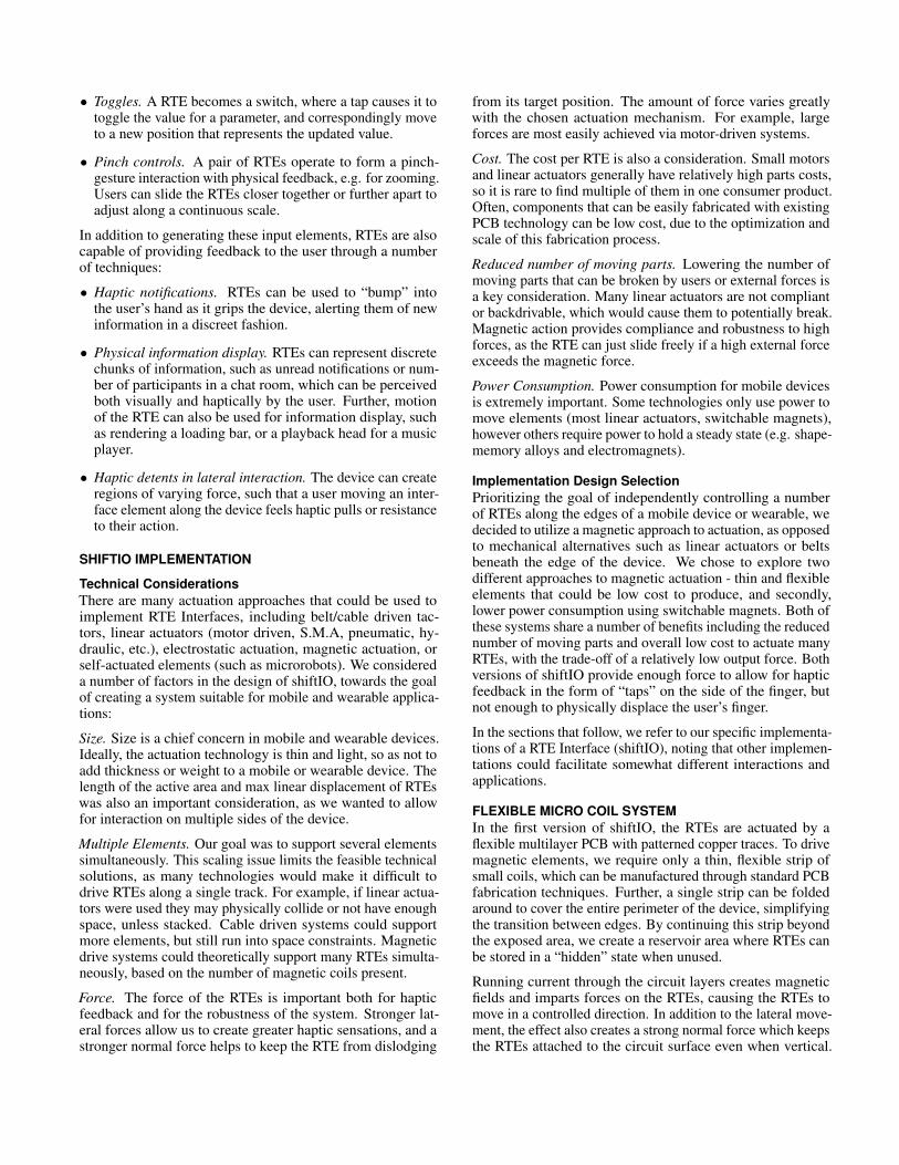
Context-Specific ControlsPhysical controls have a number of advantages over touch-screen interactions in many applications. As an example inter-action, when the user starts a game on the mobile device, twoshoulder buttons emerge to become the interface elements (SeeFigure 15). The elements could also dynamically move in cor-respondence with game elements, such as acting as physicalpaddles in a game of Pong.
Self-Adjusting Interface ElementsInterface elements can adjust to accommodate new modes orstates. For example, when the user opens a camera application,a physical shutter button appears, to allow the taking of photoswithout the need to locate a graphical button on the screen.Further, when the device is rotated, the button can adjust toensure that the control always remains in the user’s preferredposition (e.g. top right). We can similarly have physical
ShoulderButton
Figure 15: Two tactile elements appear as dynamic, physicalshoulder buttons with touch input for a mobile video game.
scrollbars or other indicators which adjust to render the stateof the application.
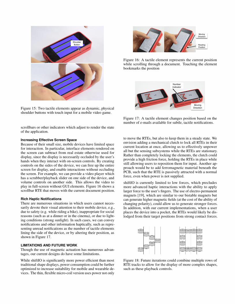
Increasing Effective Screen SpaceBecause of their small size, mobile devices have limited spacefor interaction. In particular, interface elements rendered onthe screen can subtract from real estate otherwise used fordisplay, since the display is necessarily occluded by the user’shands when they interact with on-screen controls. By creatingcontrols on the sides of the device, we can free up the entirescreen for display, and enable interactions without occludingthe screen. For example, we can provide a video player whichhas a scrubber/playback slider on one side of the device, andvolume controls on another side. This allows the video toplay in full-screen without GUI elements. Figure 16 shows ascrollbar RTE that moves with the current document position.
Rich Haptic NotificationsThere are numerous situations in which users cannot neces-sarily devote their visual attention to their mobile device, e.g.,due to safety (e.g. while riding a bike), inappropriate for socialreasons (such as at a dinner or in the cinema), or due to light-ing conditions (strong sunlight). In such cases, we can conveynotifications and other information haptically, such as repre-senting unread notifications as the number of tactile elementslining the side of the device, or by altering their position, asshown in Figure 17.
LIMITATIONS AND FUTURE WORKThough the use of magnetic actuation has numerous advan-tages, our current designs do have some limitations.
While shiftIO is significantly more power efficient than mosttraditional shape displays, power consumption could be furtheroptimized to increase suitability for mobile and wearable de-vices. The thin, flexible micro-coil version uses power not only
Moving Direction
Reading Position
Figure 16: A tactile element represents the current positionwhile scrolling through a document. Touching the elementbookmarks the position
Moving Direction
Number Indicator
Figure 17: A tactile element changes position based on thenumber of e-mails available for subtle, tactile notifications.
to move the RTEs, but also to keep them in a steady state. Weenvision adding a mechanical clutch to lock all RTEs in theircurrent location at once, allowing us to effectively unpowerall but the sensing subsystems while the RTEs are stationary.Rather than completely locking the elements, the clutch couldprovide a high friction force, holding the RTEs in place whilestill allowing users to reposition them for input. Another ap-proach would be to add ferromagnetic material beneath thePCB, such that the RTE is passively attracted with a normalforce, even when power is not supplied.
shiftIO is currently limited to low forces, which precludesmore advanced haptic interactions with the ability to applylarger force to the user’s fingers. The use of electro-permanentmagnets [19], which are similar to our bistable magnets butcan generate higher magnetic fields (at the cost of the ability ofchanging polarity), could allow us to generate stronger forces.In addition, with our current implementations, when a userplaces the device into a pocket, the RTEs would likely be dis-lodged from their target positions from strong contact forces.
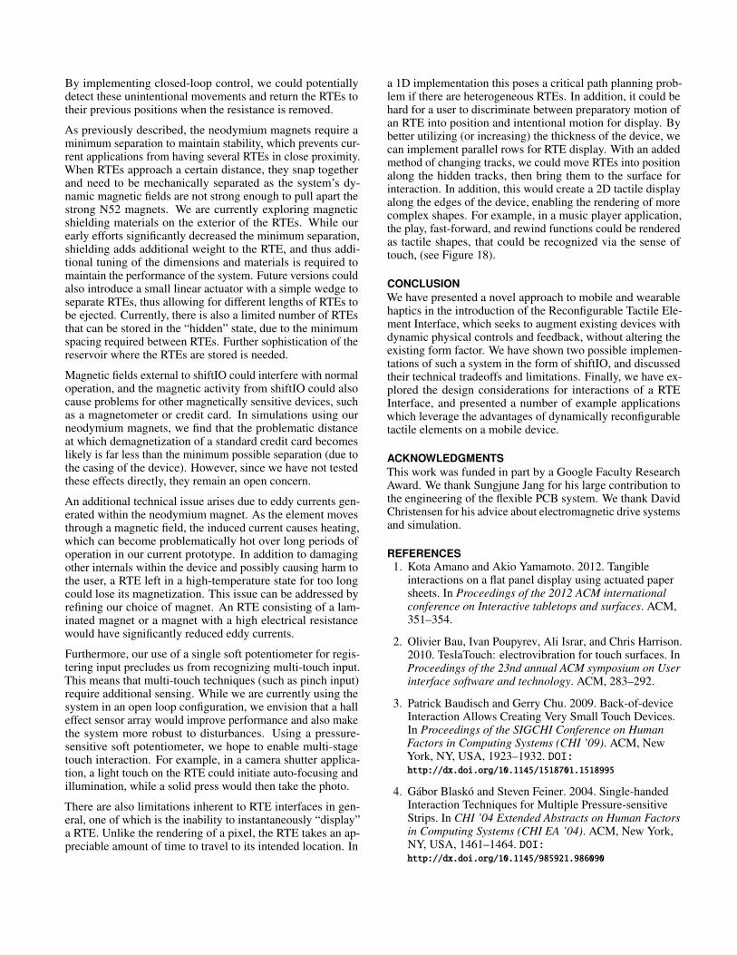
Figure 18: Future iterations could combine multiple rows ofRTE tracks to allow for the display of more complex shapes,such as these playback controls.
By implementing closed-loop control, we could potentiallydetect these unintentional movements and return the RTEs totheir previous positions when the resistance is removed.
As previously described, the neodymium magnets require aminimum separation to maintain stability, which prevents cur-rent applications from having several RTEs in close proximity.When RTEs approach a certain distance, they snap togetherand need to be mechanically separated as the system’s dy-namic magnetic fields are not strong enough to pull apart thestrong N52 magnets. We are currently exploring magneticshielding materials on the exterior of the RTEs. While ourearly efforts significantly decreased the minimum separation,shielding adds additional weight to the RTE, and thus addi-tional tuning of the dimensions and materials is required tomaintain the performance of the system. Future versions couldalso introduce a small linear actuator with a simple wedge toseparate RTEs, thus allowing for different lengths of RTEs tobe ejected. Currently, there is also a limited number of RTEsthat can be stored in the “hidden” state, due to the minimumspacing required between RTEs. Further sophistication of thereservoir where the RTEs are stored is needed.
Magnetic fields external to shiftIO could interfere with normaloperation, and the magnetic activity from shiftIO could alsocause problems for other magnetically sensitive devices, suchas a magnetometer or credit card. In simulations using ourneodymium magnets, we find that the problematic distanceat which demagnetization of a standard credit card becomeslikely is far less than the minimum possible separation (due tothe casing of the device). However, since we have not testedthese effects directly, they remain an open concern.
An additional technical issue arises due to eddy currents gen-erated within the neodymium magnet. As the element movesthrough a magnetic field, the induced current causes heating,which can become problematically hot over long periods ofoperation in our current prototype. In addition to damagingother internals within the device and possibly causing harm tothe user, a RTE left in a high-temperature state for too longcould lose its magnetization. This issue can be addressed byrefining our choice of magnet. An RTE consisting of a lam-inated magnet or a magnet with a high electrical resistancewould have significantly reduced eddy currents.
Furthermore, our use of a single soft potentiometer for regis-tering input precludes us from recognizing multi-touch input.This means that multi-touch techniques (such as pinch input)require additional sensing. While we are currently using thesystem in an open loop configuration, we envision that a halleffect sensor array would improve performance and also makethe system more robust to disturbances. Using a pressure-sensitive soft potentiometer, we hope to enable multi-stagetouch interaction. For example, in a camera shutter applica-tion, a light touch on the RTE could initiate auto-focusing andillumination, while a solid press would then take the photo.
There are also limitations inherent to RTE interfaces in gen-eral, one of which is the inability to instantaneously “display”a RTE. Unlike the rendering of a pixel, the RTE takes an ap-preciable amount of time to travel to its intended location. In
a 1D implementation this poses a critical path planning prob-lem if there are heterogeneous RTEs. In addition, it could behard for a user to discriminate between preparatory motion ofan RTE into position and intentional motion for display. Bybetter utilizing (or increasing) the thickness of the device, wecan implement parallel rows for RTE display. With an addedmethod of changing tracks, we could move RTEs into positionalong the hidden tracks, then bring them to the surface forinteraction. In addition, this would create a 2D tactile displayalong the edges of the device, enabling the rendering of morecomplex shapes. For example, in a music player application,the play, fast-forward, and rewind functions could be renderedas tactile shapes, that could be recognized via the sense oftouch, (see Figure 18).
CONCLUSIONWe have presented a novel approach to mobile and wearablehaptics in the introduction of the Reconfigurable Tactile Ele-ment Interface, which seeks to augment existing devices withdynamic physical controls and feedback, without altering theexisting form factor. We have shown two possible implemen-tations of such a system in the form of shiftIO, and discussedtheir technical tradeoffs and limitations. Finally, we have ex-plored the design considerations for interactions of a RTEInterface, and presented a number of example applicationswhich leverage the advantages of dynamically reconfigurabletactile elements on a mobile device.
ACKNOWLEDGMENTSThis work was funded in part by a Google Faculty ResearchAward. We thank Sungjune Jang for his large contribution tothe engineering of the flexible PCB system. We thank DavidChristensen for his advice about electromagnetic drive systemsand simulation.
REFERENCES1. Kota Amano and Akio Yamamoto. 2012. Tangible
interactions on a flat panel display using actuated papersheets. In Proceedings of the 2012 ACM internationalconference on Interactive tabletops and surfaces. ACM,351–354.
2. Olivier Bau, Ivan Poupyrev, Ali Israr, and Chris Harrison.2010. TeslaTouch: electrovibration for touch surfaces. InProceedings of the 23nd annual ACM symposium on Userinterface software and technology. ACM, 283–292.
3. Patrick Baudisch and Gerry Chu. 2009. Back-of-deviceInteraction Allows Creating Very Small Touch Devices.In Proceedings of the SIGCHI Conference on HumanFactors in Computing Systems (CHI ’09). ACM, NewYork, NY, USA, 1923–1932. DOI:http://dx.doi.org/10.1145/1518701.1518995
4. Gábor Blaskó and Steven Feiner. 2004. Single-handedInteraction Techniques for Multiple Pressure-sensitiveStrips. In CHI ’04 Extended Abstracts on Human Factorsin Computing Systems (CHI EA ’04). ACM, New York,NY, USA, 1461–1464. DOI:http://dx.doi.org/10.1145/985921.986090
5. Stephen Brewster, Faraz Chohan, and Lorna Brown.2007. Tactile Feedback for Mobile Interactions. InProceedings of the SIGCHI Conference on HumanFactors in Computing Systems (CHI ’07). ACM, NewYork, NY, USA, 159–162. DOI:http://dx.doi.org/10.1145/1240624.1240649
6. Alex Butler, Shahram Izadi, and Steve Hodges. 2008.SideSight: Multi-"Touch" Interaction Around SmallDevices. In Proceedings of the 21st Annual ACMSymposium on User Interface Software and Technology(UIST ’08). ACM, New York, NY, USA, 201–204. DOI:http://dx.doi.org/10.1145/1449715.1449746
7. David Cappelleri, Dimitrios Efthymiou, AsheshGoswami, Nikolaos Vitoroulis, and Michael Zavlanos.2014. Towards mobile microrobot swarms for additivemicromanufacturing. International Journal of AdvancedRobotic Systems 11 (2014).
8. Craig Michael Ciesla and Micah B Yairi. 2012. TactusUser interface system. (April 10 2012). US Patent8,154,527.
9. Ronald S Fearing. 1996. A planar milli-robot system onan air bearing. In Robotics Research. Springer, 570–581.
10. John Hardy, Christian Weichel, Faisal Taher, John Vidler,and Jason Alexander. 2015. ShapeClip: Towards RapidPrototyping with Shape-Changing Displays for Designers.In Proceedings of the 33rd Annual ACM Conference onHuman Factors in Computing Systems (CHI ’15). ACM,New York, NY, USA, 19–28. DOI:http://dx.doi.org/10.1145/2702123.2702599
11. Chris Harrison and Scott E Hudson. 2009. Providingdynamically changeable physical buttons on a visualdisplay. In Proceedings of the SIGCHI Conference onHuman Factors in Computing Systems. ACM, 299–308.
12. Fabian Hemmert, Gesche Joost, André Knörig, and RetoWettach. 2008. Dynamic knobs: shape change as a meansof interaction on a mobile phone. In CHI’08 ExtendedAbstracts on Human Factors in Computing Systems.ACM, 2309–2314.
13. David Holman, Andreas Hollatz, Amartya Banerjee, andRoel Vertegaal. 2013. Unifone: Designing for AuxiliaryFinger Input in One-handed Mobile Interactions. InProceedings of the 7th International Conference onTangible, Embedded and Embodied Interaction (TEI ’13).ACM, New York, NY, USA, 177–184. DOI:http://dx.doi.org/10.1145/2460625.2460653
14. Sungjae Hwang, Myungwook Ahn, and Kwang-yunWohn. 2013. MagGetz: customizable passive tangiblecontrollers on and around conventional mobile devices. InProceedings of the 26th annual ACM symposium on Userinterface software and technology. ACM, 411–416.
15. Hiroshi Ishii and Brygg Ullmer. 1997. Tangible bits:towards seamless interfaces between people, bits andatoms. In Proceedings of the ACM SIGCHI Conferenceon Human factors in computing systems. ACM, 234–241.
16. Sungjune Jang, Lawrence H. Kim, Kesler Tanner, HiroshiIshii, and Sean Follmer. 2016. Haptic Edge Display forMobile Tactile Interaction. In Proceedings of the 2016CHI Conference on Human Factors in ComputingSystems (CHI ’16). ACM, New York, NY, USA,3706–3716. DOI:http://dx.doi.org/10.1145/2858036.2858264
17. Yvonne Jansen, Pierre Dragicevic, and Jean-DanielFekete. 2012. Tangible Remote Controllers for Wall-sizeDisplays. In Proceedings of the SIGCHI Conference onHuman Factors in Computing Systems (CHI ’12). ACM,New York, NY, USA, 2865–2874. DOI:http://dx.doi.org/10.1145/2207676.2208691
18. Wuming Jing, Nicholas Pagano, and David J Cappelleri.2013. A novel micro-scale magnetic tumbling microrobot.Journal of Micro-Bio Robotics 8, 1 (2013), 1–12.
19. Ara Nerses Knaian. 2010. Electropermanent magneticconnectors and actuators: devices and their applicationin programmable matter. Ph.D. Dissertation.Massachusetts Institute of Technology.
20. Mathieu Le Goc, Lawrence H. Kim, Ali Parsaei,Jean-Daniel Fekete, Pierre Dragicevic, and Sean Follmer.2016. Zooids: Building Blocks for Swarm UserInterfaces. In Proceedings of the 29th Annual Symposiumon User Interface Software and Technology (UIST ’16).ACM, New York, NY, USA, 97–109. DOI:http://dx.doi.org/10.1145/2984511.2984547
21. Joseph Luk, Jerome Pasquero, Shannon Little, KaronMacLean, Vincent Levesque, and Vincent Hayward.2006. A Role for Haptics in Mobile Interaction: InitialDesign Using a Handheld Tactile Display Prototype. InProceedings of the SIGCHI Conference on HumanFactors in Computing Systems (CHI ’06). ACM, NewYork, NY, USA, 171–180. DOI:http://dx.doi.org/10.1145/1124772.1124800
22. David Meeker. 2014. Finite Element Method Magnets.(2014). http://www.femm.info/wiki Accessed Aug. 2016.
23. Gian Pangaro, Dan Maynes-Aminzade, and Hiroshi Ishii.2002. The Actuated Workbench: Computer-controlledActuation in Tabletop Tangible Interfaces. In Proceedingsof the 15th Annual ACM Symposium on User InterfaceSoftware and Technology (UIST ’02). ACM, New York,NY, USA, 181–190. DOI:http://dx.doi.org/10.1145/571985.572011
24. J. Pasquero, J. Luk, V. Levesque, Qi Wang, V. Hayward,and K.E. MacLean. 2007. Haptically Enabled HandheldInformation Display With Distributed Tactile Transducer.Multimedia, IEEE Transactions on 9, 4 (June 2007),746–753. DOI:http://dx.doi.org/10.1109/TMM.2007.895672
25. James Patten and Hiroshi Ishii. 2007. MechanicalConstraints As Computational Constraints in TabletopTangible Interfaces. In Proceedings of the SIGCHIConference on Human Factors in Computing Systems(CHI ’07). ACM, New York, NY, USA, 809–818. DOI:http://dx.doi.org/10.1145/1240624.1240746
26. Esben Warming Pedersen and Kasper Hornbæk. 2011.Tangible Bots: Interaction with Active Tangibles inTabletop Interfaces. In Proceedings of the SIGCHIConference on Human Factors in Computing Systems(CHI ’11). ACM, New York, NY, USA, 2975–2984. DOI:http://dx.doi.org/10.1145/1978942.1979384
27. Ron Pelrine. 1992. Magnetically levitated apparatus.(March 24 1992). US Patent 5,099,216.
28. Ron Pelrine, Annjoe Wong-Foy, Brian McCoy, DennisHoleman, Rich Mahoney, Greg Myers, Jim Herson, andTony Low. 2012. Diamagnetically levitated robots: Anapproach to massively parallel robotic systems withunusual motion properties. In Robotics and Automation(ICRA), 2012 IEEE International Conference on. IEEE,739–744.
29. Ivan Poupyrev and Shigeaki Maruyama. 2003. Tactileinterfaces for small touch screens. In Proceedings of the16th annual ACM symposium on User interface softwareand technology. ACM, 217–220.
30. Simon Robinson, Céline Coutrix, Jennifer Pearson, JuanRosso, Matheus Fernandes Torquato, Laurence Nigay,and Matt Jones. 2016. Emergeables: DeformableDisplays for Continuous Eyes-Free Mobile Interaction. InProceedings of the 2016 CHI Conference on HumanFactors in Computing Systems (CHI ’16). ACM, NewYork, NY, USA, 3793–3805. DOI:http://dx.doi.org/10.1145/2858036.2858097
31. Dan Rosenfeld, Michael Zawadzki, Jeremi Sudol, andKen Perlin. 2004. Physical objects as bidirectional userinterface elements. Computer Graphics and Applications,IEEE 24, 1 (2004), 44–49.
32. Evan Strasnick and Sean Follmer. 2016. Applications ofSwitchable Permanent Magnetic Actuators in Shape
Change and Tactile Display. In Proceedings of the 29thAnnual ACM Symposium on User Interface Software andTechnology (UIST ’16). ACM, Tokyo, Japan, 4. DOI:http://dx.doi.org/10.1145/2984751.2985728
33. John Tiab and Kasper Hornbæk. 2016. UnderstandingAffordance, System State, and Feedback inShape-Changing Buttons. In Proceedings of the 2016CHI Conference on Human Factors in ComputingSystems. ACM, 2752–2763.
35. Nicolas Villar and Hans Gellersen. 2007. A malleablecontrol structure for softwired user interfaces. InProceedings of the 1st international conference onTangible and embedded interaction. ACM, 49–56.
36. Akira Wakita, Akito Nakano, and Nobuhiro Kobayashi.2011. Programmable blobs: a rheologic interface fororganic shape design. In Proceedings of the fifthinternational conference on Tangible, embedded, andembodied interaction. ACM, 273–276.
37. Malte Weiss, Florian Schwarz, Simon Jakubowski, andJan Borchers. 2010. Madgets: Actuating Widgets onInteractive Tabletops. In Proceedings of the 23Nd AnnualACM Symposium on User Interface Software andTechnology (UIST ’10). ACM, New York, NY, USA,293–302. DOI:http://dx.doi.org/10.1145/1866029.1866075
38. Malte Weiss, Chat Wacharamanotham, Simon Voelker,and Jan Borchers. 2011. FingerFlux: near-surface hapticfeedback on tabletops. In Proceedings of the 24th annualACM symposium on User interface software andtechnology. ACM, 615–620.