NTIS # PB2008- SSC-453 WELDING DISTORTION ANALYSIS OF HULL BLOCKS USING EQUIVALENT LOAD METHOD BASED ON INHERENT STRAIN This document has been approved For public release and sale; its Distribution is unlimited SHIP STRUCTURE COMMITTEE 2008
Transcript
NTIS # PB2008-
SSC-453
WELDING DISTORTION ANALYSIS
OF HULL BLOCKS USING EQUIVALENT LOAD METHOD BASED ON INHERENT STRAIN
This document has been approved For public release and sale; its
Distribution is unlimited
SHIP STRUCTURE COMMITTEE 2008
Ship Structure Committee
RADM Brian M. Salerno U. S. Coast Guard Assistant Commandant,
Assistant Commandant for Marine Safety, Security and Stewardship Chairman, Ship Structure Committee
{Name} {Title}
Naval Sea Systems Command
Dr. Roger Basu Senior Vice President
American Bureau of Shipping
Mr. Joseph Byrne Director, Office of Ship Construction
Maritime Administration
Mr. William Nash Director General, Marine Safety,
Safety & Security Transport Canada
Mr. Kevin Baetsen
Director of Engineering Military Sealift Command
Dr. Neil Pegg Group Leader - Structural Mechanics
Defence Research & Development Canada - Atlantic
CONTRACTING OFFICER TECHNICAL REP. Mr. Chao Lin / MARAD Mr. Glenn Ashe / ABS
DRDC / USCG
EXECUTIVE DIRECTOR Lieutenant Commander, Jason Smith
U. S. Coast Guard
SHIP STRUCTURE SUB-COMMITTEE
AMERICAN BUREAU OF SHIPPING DEFENCE RESEARCH & DEVELOPMENT CANADA
ATLANTIC Mr. Glenn Ashe
Mr. Derek Novak Mr. Phil Rynn
Mr. Balji Menon
Dr. David Stredulinsky Mr. John Porter
MARITIME ADMINISTRATION MILITARY SEALIFT COMMAND
Mr. Chao Lin Mr. Carl Setterstrom
Mr. Richard Sonnenschein
Mr. Michael W. Touma Mr. Paul Handler
ONR / NAVY/ NSWCCD TRANSPORT CANADA
{Name} {Name} {Name} {Name}
Paul Denis Vallee
US COAST GUARD SOCIETY OF NAVAL ARCHITECTS AND MARINE
4. Title and Subtitle Welding Distortion Analysis of Hull Blocks Using
5. Report Date September 11, 2007
Equivalent Load Method Based on Inherent Strain 6. Performing Organization Code
7. Author(s) C.D. Jang
8. Performing Organization Report No. SR-1450
9. Performing Organization Name and Address Seoul National University
10. Work Unit No. (TRAIS)
Department of Naval Architecture & Ocean Engineering San 56-1, Shillim-Dong, Gwanak-Gu Seoul 151-742 , KOREA
11. Contract or Grant No.
12. Sponsoring Agency Name and Address Ship Structure Committee C/O Commandant (CG-5212/SSC) United States Coast Guard
13. Type of Report Final Report
2100 2nd Street, SW Washington, DC 20593-0001
14. Sponsoring Agency Code
CG - 5 15. Supplementary Notes Sponsored by the Ship Structure Committee and its member agencies 16. Abstract This paper suggests an efficient method (Equivalent Load Method) for predicting the welding deformation of stiffened curved plates based on the inherent strain theory combined with the finite element method. The proposed method can predict the various modes of welding distortions of stiffened curved plates such as angular distortion, in-plane shrinkage, longitudinal and transverse bending deformations considering welding sequence according to the fabrication stages. The equivalent load was determined by integrating inherent strain components which are calculated in the vicinity of heat affected zone using the highest temperature and the degree of restraint. The welding distortions of curved stiffened panels under equivalent load were calculated by elastic analysis and compared with those by the experiment as well as the thermal elasto-plastic finite element analysis. The welding distortions of stiffened curved plates by the proposed method showed fairly good agreements with those by the experiment and intensive finite element analysis. It has been verified that the proposed method has a high efficiency and accuracy. By the proposed method, it was possible to predict the welding distortion of a curved double bottom block of actual ship. Due to its efficiency and accuracy, the present method can provide a powerful solution to predict the welding distortion of actual ship hull blocks with high complexity in structural shape. 17. Key Words Aluminum structure, marine structure, aluminum design, aluminum fabrication
18. Distribution Statement National Technical Information Service U.S. Department of Commerce Springfield, VA 22151 Ph. (703) 487-4650 / www.ntis.gov
19. Security Classif. (of this report) Unclassified
20. Security Classif. (of this page)
Unclassified
21. No. of Pages
22. Price
CONVERSION FACTORS
(Approximate conversions to metric measures) To convert from to Function Value
LENGTH inches meters divide 39.3701 inches millimeters multiply by 25.4000 feet meters divide by 3.2808 VOLUME cubic feet cubic meters divide by 35.3149 cubic inches cubic meters divide by 61,024 SECTION MODULUS inches2 feet2 centimeters2 meters2 multiply by 1.9665 inches2 feet2 centimeters3 multiply by 196.6448 inches4 centimeters3 multiply by 16.3871 MOMENT OF INERTIA inches2 feet2 centimeters2 meters divide by 1.6684 inches2 feet2 centimeters4 multiply by 5993.73 inches4 centimeters4 multiply by 41.623 FORCE OR MASS long tons tonne multiply by 1.0160 long tons kilograms multiply by 1016.047 pounds tonnes divide by 2204.62 pounds kilograms divide by 2.2046 pounds Newtons multiply by 4.4482 PRESSURE OR STRESS pounds/inch2 Newtons/meter2 (Pascals) multiply by 6894.757 kilo pounds/inch2 mega Newtons/meter2
(mega Pascals) multiply by 6.8947
BENDING OR TORQUE foot tons meter tons divide by 3.2291 foot pounds kilogram meters divide by 7.23285 foot pounds Newton meters multiply by 1.35582 ENERGY foot pounds Joules multiply by 1.355826 STRESS INTENSITY kilo pound/inch2 inch½(ksi√in) mega Newton MNm3/2 multiply by 1.0998 J-INTEGRAL kilo pound/inch Joules/mm2 multiply by 0.1753 kilo pound/inch kilo Joules/m2 multiply by 175.3
8. Plan of experiments ..............................................................................................................................64
9.3. Comparison of welding deformation between experiment and analysis………….69 10. Welding distortion analysis of a stiffened curved panel block by equivalent load method ..........74
10.1. Dimension and welding heat input of a curved double bottom block............................ 74
10.2. Heat transfer analysis ............................................................................................. 77
10.3. Calculation of degree of restraint ............................................................................. 77
10.4. Prediction of welding deformation of a curved double bottom block by equivalent load
- Multiple welding passes,various welding methods and many fabrication stages
- Huge computation time and cost.
In order to overcome above difficulties, some efficient approaches to predict the welding
distortion of the actual ship hull blocks are needed, but have not been well established yet.
For the development of an efficient approach to predict the welding distortion of actual ship hull
blocks considering the fabrication sequences and phase transformation of steel, the analysis method
should satisfy the following requirements.
● The analysis method should be capable of considering the various modes of welding
distortions such as longitudinal/transverse shrinkage and longitudinal/transversal bending
simultaneously.
● The analysis should reflect the change of structural stiffness according to the fabrication
stages.
● The analysis should be able to consider the welding sequence.
9
● The analysis should reflect the change of phase transformation of steel by material properties
● The efficiency of calculation time and cost should be guaranteed considering the complexity
of hull block shapes.
● The analysis method should predict the distortion of not only the stiffened flat plates but also
of stiffened curved plates.
1.2 Objectives
The main purpose of this study is to propose an efficient approach to predict the welding
distortions of the stiffened flat and curved plates based on the inherent strain theory combined with the
finite element analysis. In order to verify the efficiency and the effectiveness of this method, some
numerical simulation and experiments of welding distortions of various stiffened and curved plates with
the different curvatures considering the different fabrication sequences will be performed.
10
2. Development of equivalent load method for welding distortion analysis based on inherent strain 2.1. Inherent strain due to welding
In the welding process, the heat input around a weld joint causes a non-uniform temperature
distribution and thermal stress. As a result, the plastic strain remains around the weld bead and
permanent deformation occurs after welding. The plastic strain that causes the welding deformation
can be defined as the inherent strain. In general, the inherent strain induced by welding has six
components according to their directions. However, in the case where a plate has a large length/thickness ratio such as a ship hull plate, only two components ∗
xε and ∗yε are dominant.
Some typical types of welding deformation due to inherent strain are shown in Fig. 1.
Fig. 1 Types of welding deformation
2.1.1. Calculation of the inherent strain
The inherent strain distribution can be formulated using a simplified thermal elasto-plastic
analysis model as shown in Fig. 2. The welding region, where inherent strain occurs, can be
modeled as a bar and a spring.
Fig. 2 Simplified thermal elasto-plastic analysis model
11
Fig. 3 Thermal history of plastic strain
The thermal history of the inherent strain according to the temperature change of a bar can be
divided into four steps, as shown in Fig. 3. After all the thermal history the compressive plastic strain remains as an amount of ∗
pε . The magnitude of residual plastic strain was calculated from
the total strain, the stress-strain relation and the equilibrium equation of a bar-spring system.
Total strain : peth εεεε ++= (1)
Stress-strain relation : eEεσ = (2)
Equilibrium equation : SB FF = (3)
2.1.2. Distribution of the highest temperature
The highest temperature means the maximum temperature that each point in the heat effected
region experiences through whole welding time. The heat transfer analysis is conducted to
calculate the temperature distribution of welded structures. The welding heat source is modeled
as a normal distributed moving heat flux. Finally, the highest temperature at each node in the
finite element model is calculated by the heat transfer analysis.
The temperature of bar is changed from the room temperature 0max0 TTT →→ . If the
highest temperature ( maxT ) is reached sufficiently high, the section is divided in 4 steps shown
in Fig. 4. The section of OA, AB is elastic and plastic process during a temperature rising and
the section of BC, CD is elastic and plastic process during a temperature falling.
12
Fig. 4 Thermal history of stress
If a material nonlinearity is considered, thermal histories of stress and plastic strain are shown in
Fig. 5.
Fig. 5 Comparison of stress and plastic strain considering material nonlinearity
2.1.3. Calculation of degree of restraint
The degree of restraint represents the level of resistance against the thermal deformation of the
welding region. The degree of restraint of stiffened panel is determined from the analogy of the
bar-spring model and the elastic finite element analysis using unit load.
Since the fabrication process will greatly affect the welding deformation, the degree of
structural restraint should be calculated considering all the fabrication sequences.
13
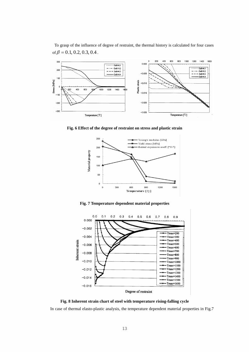
To grasp of the influence of degree of restraint, the thermal history is calculated for four cases
of 4.0,3.0,2.0,1.0=β .
Fig. 6 Effect of the degree of restraint on stress and plastic strain
Fig. 7 Temperature dependent material properties
Fig. 8 Inherent strain chart of steel with temperature rising-falling cycle
In case of thermal elasto-plastic analysis, the temperature dependent material properties in Fig.7
14
should be incorporated in the numerical calculation. The final inherent strain after thermal cycle
can be determined using the highest temperature and degree of restraints shown in Fig.8.
In this report, the highest temperature is divided by 50℃ from 0℃ to 2500℃ and the degree of
restraint is divided by 0.01 intervals from 0.01 to 0.99.
2.1.4. Phase transformation by cooling rate
Heat transfer analysis is conducted to calculate the cooling rate. Phase transformation of steel
was determined by cooling rate as shown in Fig. 9.
Fig. 9 CCTD(Continuous cooling transformation diagrams) at C=0.18% steel
2.2. Calculation of equivalent loads The equivalent forces and moments are obtained by using the inherent strain. Using the obtained
equivalent loads, the welding deformation can be calculated by elastic FE analysis. All types of
equivalent loads are shown in Fig. 9. The shrinkage force if can be obtained using Eq. (4).
∑=
∗=iN
jjji l
lAEf
1ε (4)
The equivalent transverse forces and moments are calculated using Eq. (5) and Eq. (6), respectively.
∑=
=N
iiy ff
1
(5)
∑=
=N
iiiy zfm
1
(6)
15
Also the longitudinal shrinkage force xf and bending moment xm can be calculated using
inherent strain.
Fig. 10 Equivalent loads of inherent strain
2.3. Simulation of welding deformation The welding deformation of curved stiffened panel blocks will be simulated using both the
equivalent load method based on inherent strain and FE analysis. The simulation procedures can be
summarized into three steps. The first step analyzes heat transfer to calculate temperature
distribution of each welding section with the given information on welding parameters. The FE
model uses heat conduction elements and considers convection on the surface. And cooling rate is
calculated to determine phase transformation. The second step computes the degree of restraint by
the FE analysis. The third step calculates the inherent strain components and their equivalent loads,
and the welding deformation of a structure is obtained by FE analysis.
By using this equivalent load approach, the simulation for welding deformation of stiffened curved
panel blocks will be performed based on the results of experiment and finite element analysis of
simple curved plate models with one or two stiffeners.
16
3. Prediction of welding deformation of stiffened plates using thermal elasto-plastic analysis
APDL(ANSYS Parametric Design Language) is used to perform the finite element simulation. Each
flat plate and curved plate has 4 kinds of analysis models.
3.1. Thermal elasto-plastic analysis of stiffened flat plates 3.1.1. Models of thermal elasto-plastic analysis of stiffened flat plates
Fig. 11 Models of thermal elasto-plastic analysis of stiffened flat plates
Four kinds of analysis models of stiffened flat plate are adopted. The 1st model has 1
longitudinal stiffener and no transverse stiffener. And the 2nd, 3rd, 4th model has each 1, 2 and 3
stiffeners. Each model has a same base flat plate of L(600mm)×B(400mm)×h(16mm) and a same
longitudinal stiffener of L(600mm)×B(16mm)×h(200mm). And the size of each transverse
stiffener is same as L(8mm)×B(400mm)×h(100mm). The longitudinal stiffeners are equally
spaced and located at )(150 mmz −= , )(300 mmz −= , )(450 mmz −= respectively.
17
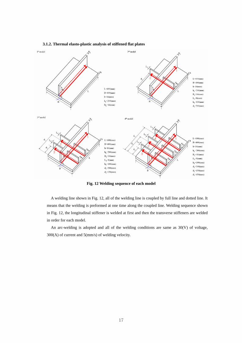
3.1.2. Thermal elasto-plastic analysis of stiffened flat plates
Fig. 12 Welding sequence of each model
A welding line shown in Fig. 12, all of the welding line is coupled by full line and dotted line. It
means that the welding is preformed at one time along the coupled line. Welding sequence shown
in Fig. 12, the longitudinal stiffener is welded at first and then the transverse stiffeners are welded
in order for each model.
An arc-welding is adopted and all of the welding conditions are same as 30(V) of voltage,
300(A) of current and 5(mm/s) of welding velocity.
18
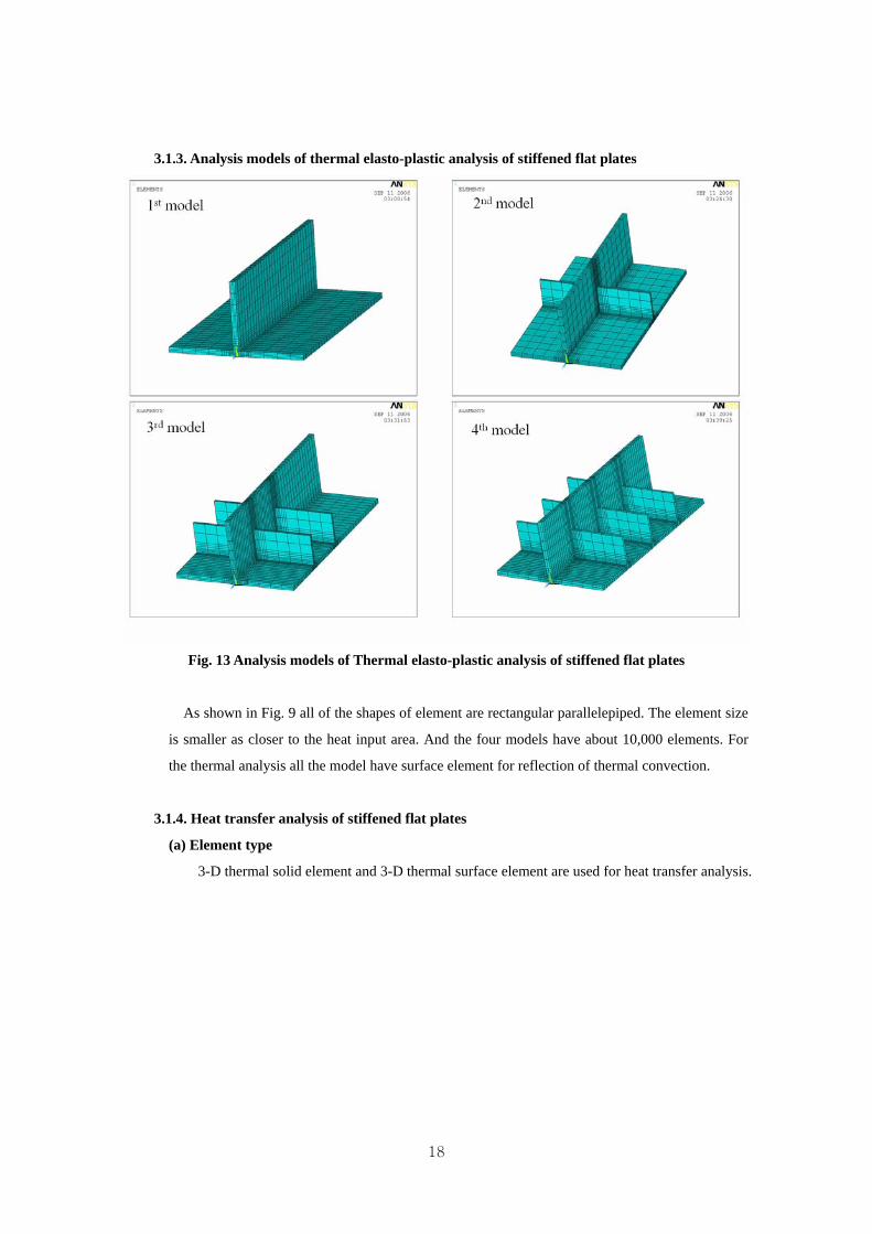
3.1.3. Analysis models of thermal elasto-plastic analysis of stiffened flat plates
Fig. 13 Analysis models of Thermal elasto-plastic analysis of stiffened flat plates
As shown in Fig. 9 all of the shapes of element are rectangular parallelepiped. The element size
is smaller as closer to the heat input area. And the four models have about 10,000 elements. For
the thermal analysis all the model have surface element for reflection of thermal convection.
3.1.4. Heat transfer analysis of stiffened flat plates
(a) Element type
3-D thermal solid element and 3-D thermal surface element are used for heat transfer analysis.
19
Fig. 14 3-D thermal solid element
The 3-D thermal solid element has eight nodes with a single degree of freedom, temperature,
at each node. The element is applicable to a 3-D, steady-state or transient thermal analysis. The
element can compensate for mass transport heat flow from a constant velocity field. The
geometry, node locations and the coordinate system for this element are shown in Fig. 14.
Fig. 15 3-D thermal surface element
The 3-D thermal surface element overlaid onto an area face of 3-D solid element. This
element is used for reflection of thermal convection. The geometry, node location and the
coordinate system for this element are shown in Fig.15. The element is defined by four to nine
nodes and material properties. An extra node may be used for convection or radiation effects.
(b) Results of heat transfer analysis
All the analysis of heat input is performed by heat flux at nodes. For reflection of the line
welding heat input process is divided several steps. The step size of heat input process is
20
100mm of welding line. So the longitudinal welding is analyzed 6 steps and the transverse
welding is analyzed 4 steps.
All the cooling process has 10 steps of cooling analysis. Right after the heat input, the
cooling step size should be small because the temperature gradient is large. As the temperature
gradient become small, the cooling step size getting larger. At the end of the cooling step, 10th
step, the temperature gradient is nearly zero.
Fig. 16 Heat input process of 1st model of stiffened flat plate
21
Fig. 17 Heat input process of 2nd model of stiffened flat plate
Fig. 18 Heat input process of 3rd model of stiffened flat plate
22
Fig. 19 Heat input process of 4th model of stiffened flat plate
3.1.5. Prediction of welding deformation of stiffened flat plates
(a) Boundary conditions
Fig. 20 Boundary conditions of stiffened flat plate
23
All of the boundary condition of stiffened flat plate is applied at the bottom of mail plate. As
shown in Fig. 20 along the middle of the breadth direction (x=0), all of nodes are fixed to x
direction. And around the middle of the length, some nodes are fixed all direction of x, y, and z.
(b) Analysis results
Fig. 21 Analysis result of 1st case of stiffened flat plate
Fig. 22 Analysis result of 2nd case of stiffened flat plate
24
Fig. 23 Analysis result of 3rd case of stiffened flat plate
Fig. 24 Analysis result of 4th case of stiffened flat plate
25
Fig. 25 Welding deformation of stiffened flat plates (Model 1)
Fig. 26 Welding deformation of stiffened flat plates (Model 2)
26
Fig. 27 Welding deformation of stiffened flat plates (Model 3)
Fig. 28 Welding deformation of stiffened flat plates (Model 4)
27
Fig. 29 Welding deformation of stiffened flat plates (Model 1)
Fig. 30 Welding deformation of stiffened flat plates (Model 2)
28
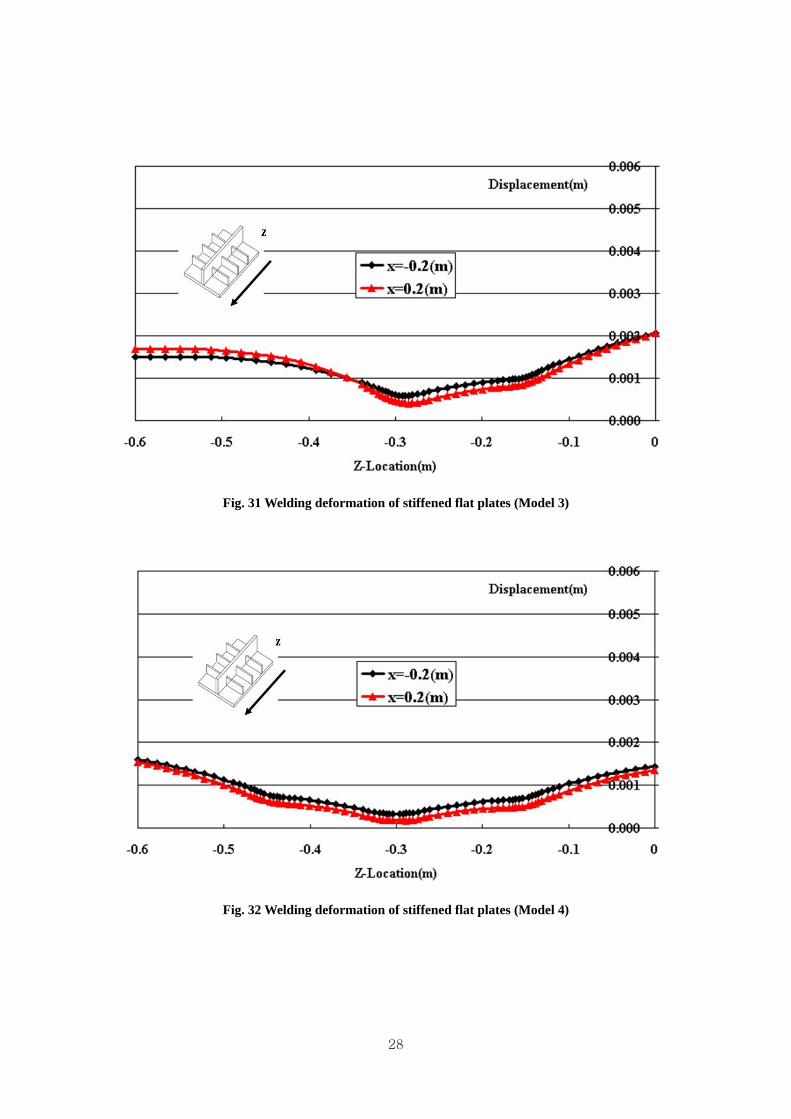
Fig. 31 Welding deformation of stiffened flat plates (Model 3)
Fig. 32 Welding deformation of stiffened flat plates (Model 4)
29
3.2. Thermal elasto-plastic analysis of stiffened curved plates 3.2.1. Models of thermal elasto-plastic analysis of stiffened curved plates
Fig. 33 Models of thermal elasto-plastic analysis of stiffened curved plates
Four kinds of analysis models of stiffened flat plate are adopted. The 1st model has 1
longitudinal stiffener and no transverse stiffener. And the 2nd, 3rd, 4th model has each 1, 2 and 3
stiffeners. Each model has a same base flat plate of L(600mm)×B(400mm)×h(16mm) and a same
longitudinal stiffener of L(600mm)×B(16mm)×h(200mm). And the size of each transverse
stiffener is same as L(8mm)×B(400mm)×h(100mm). The transverse stiffeners are equally spaced
and located at )(150 mmz −= , )(300 mmz −= , )(450 mmz −= respectively. All of the sizes of
the stiffened curved plate are same as the sizes of the stiffened flat plat.
30
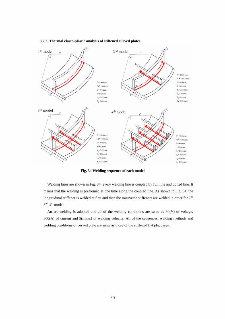
3.2.2. Thermal elasto-plastic analysis of stiffened curved plates
Fig. 34 Welding sequence of each model
Welding lines are shown in Fig. 34, every welding line is coupled by full line and dotted line. It
means that the welding is preformed at one time along the coupled line. As shown in Fig. 34, the
longitudinal stiffener is welded at first and then the transverse stiffeners are welded in order for 2nd
3rd, 4th model.
An arc-welding is adopted and all of the welding conditions are same as 30(V) of voltage,
300(A) of current and 5(mm/s) of welding velocity. All of the sequences, welding methods and
welding conditions of curved plate are same as those of the stiffened flat plat cases.
31
3.2.3. Analysis models of Thermal elasto-plastic analysis of stiffened curved plates
Fig. 35 Analysis models of Thermal elasto-plastic analysis of stiffened curved plates
As shown in Fig. 35 all of the shapes of element are rectangular parallelepiped. The element size
is smaller as closer to the heat input area. And the four models have about 10,000 elements. For the
thermal analysis all the model have surface element for reflection of thermal convection.
3.2.4. Heat transfer analysis of stiffened curved plates
In heat transfer analysis of curved plate, 3-D thermal solid element type and 3-D thermal
surface element type are used same as the stiffened flat plate case.
32
Fig. 36 Heat input process of 1st model of stiffened curved plate
33
Fig. 37 Heat input process of 2nd model of stiffened curved plate
Fig. 38 Heat input process of 3rd model of stiffened curved plate
34
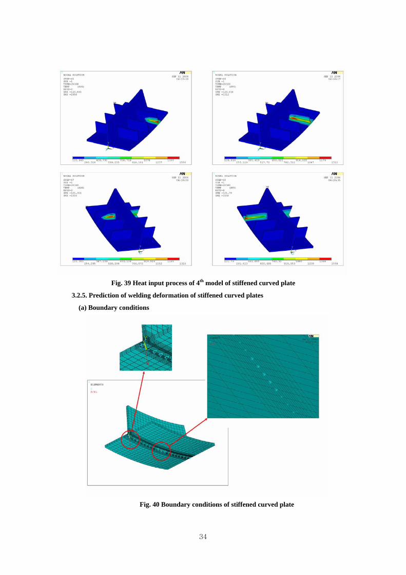
Fig. 39 Heat input process of 4th model of stiffened curved plate
3.2.5. Prediction of welding deformation of stiffened curved plates
(a) Boundary conditions
Fig. 40 Boundary conditions of stiffened curved plate
35
All of the boundary conditions of flat plate are applied at the bottom of main plate. As shown
in Fig. 40 along the middle of the breadth direction (x=0), all of nodes are fixed to x direction.
And in the middle of the length, some nodes are fixed all direction of x, y, and z. All applied
boundary conditions of curved plate are same as the stiffened flat plate.
(b) Analysis results
Fig. 41 Analysis result of 1st case of stiffened curved plate
Fig. 42 Analysis result of 2nd case of stiffened curved plate
36
Fig. 43 Analysis result of 3rd case of stiffened curved plate
Fig. 44 Analysis result of 4th case of stiffened curved plate
37
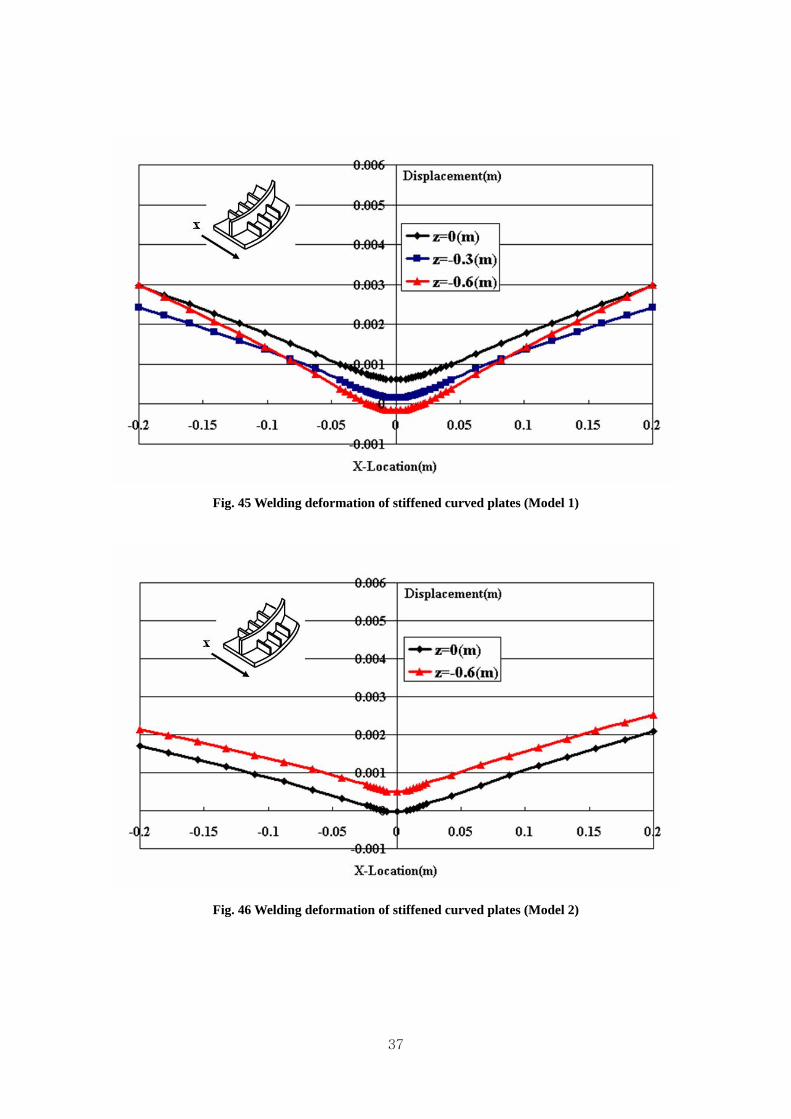
Fig. 45 Welding deformation of stiffened curved plates (Model 1)
Fig. 46 Welding deformation of stiffened curved plates (Model 2)
38
Fig. 47 Welding deformation of stiffened curved plates (Model 3)
Fig. 48 Welding deformation of stiffened curved plates (Model 4)
39
Fig. 49 Welding deformation of stiffened curved plates (Model 1)
Fig. 50 Welding deformation of stiffened curved plates (Model 2)
40
Fig. 51 Welding deformation of stiffened curved plates (Model 3)
Fig. 52 Welding deformation of stiffened curved plates (Model 4)
41
4. Welding distortion analysis of stiffened flat plate by equivalent load method By the equivalent load method, welding deformation analysis is performed for each case of the flat
plate. Analysis results are shown in Fig. 53 - 60.
Fig. 53 Welding deformation of stiffened flat plates by equivalent load method (Model 1)
Fig. 54 Welding deformation of stiffened flat plates by equivalent load method (Model 2)
42
Fig. 55 Welding deformation of stiffened flat plates by equivalent load method (Model 3)
Fig. 56 Welding deformation of stiffened flat plates by equivalent load method (Model 4)
43
Fig. 57 Welding deformation of stiffened flat plates by equivalent load method (Model 1)
Fig. 58 Welding deformation of stiffened flat plates by equivalent load method (Model 2)
44
Fig. 59 Welding deformation of stiffened flat plates by equivalent load method (Model 3)
Fig. 60 Welding deformation of stiffened flat plates by equivalent load method (Model 4)
45
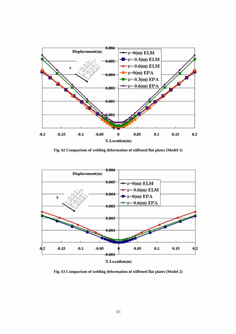
5. Comparison of thermal elasto-plastic analysis and equivalent load method of stiffened flat plates The coordinates used in this report is shown in Fig. 60
Fig. 61 Coordinates of stiffened flat plate
The welding distortions (at x=0.2m) calculated by two different methods ( EPA: Elasto-Plastic Analysis,
ELM : Equivalent Load Method) are compared in Table 1.
Both results show fairly good agreements with each other within 12% of average difference.
Table. 1 Comparison of welding distortions of stiffened flat plates(at x=0.2m)
The elastic analysis of stiffened curved plate under unit load is as follow:
53
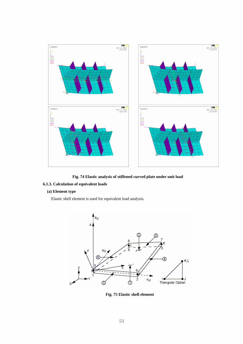
Fig. 74 Elastic analysis of stiffened curved plate under unit load
6.1.3. Calculation of equivalent loads
(a) Element type
Elastic shell element is used for equivalent load analysis.
Fig. 75 Elastic shell element
54
The adopted elastic shell element has both bending and membrane capabilities. Both in-
plane and normal loads are permitted. The element has six degrees of freedom at each node.
Stress stiffening and large deflection capabilities are included. The geometry, node location,
and the coordinate system for this element are shown in Fig. 75. The element is defined by
four nodes, four thicknesses, elastic foundation stiffness, and the orthotropic material
properties. Orthotropic material directions correspond to the element coordinate directions.
(b) Elastic analysis by equivalent load method
By the highest temperature and degree of restraint, the inherent strain can be obtained from
the inherent strain chart. The shrinkage forces and moments can be calculated as explained in
§1.2(Calculation of equivalent loads).
The shrinkage forces of stiffened flat plate and of stiffened curved plate should be applied
in different way. As shown in Fig. 76, the shrinkage force of the flat plate is applied at the
both ends of the plate. But in the curved plate case, the shrinkage force should be applied to
each node along the weld line in the tangential direction.
Fig. 76 Application of shrinkage forces
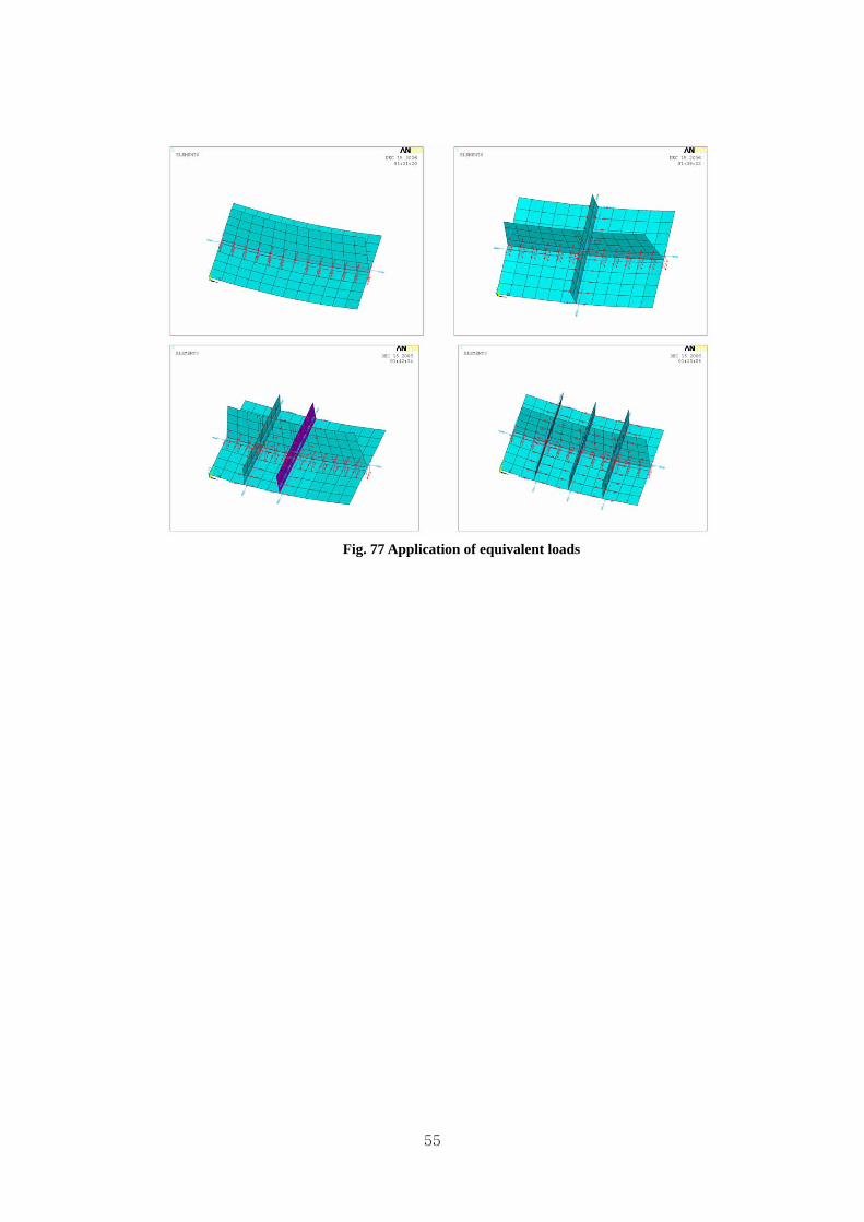
The applications of equivalent load to four cases of stiffened curved plate model are shown
in Fig. 77.
55
Fig. 77 Application of equivalent loads
56
6.2. Prediction of welding distortion of stiffened curved plates by equivalent load method
Fig.78 shows the adopted coordinates system for the stiffend curved plate.
Fig. 78 Coordinate of stiffened curved plate
By the equivalent loads method, welding deformation analysis is performed for 4 cases of the
stiffened curved plate. Analysis results are shown in Fig. 79 - 87.
Fig. 79 Welding deformation of stiffened curved plates by equivalent load method
57
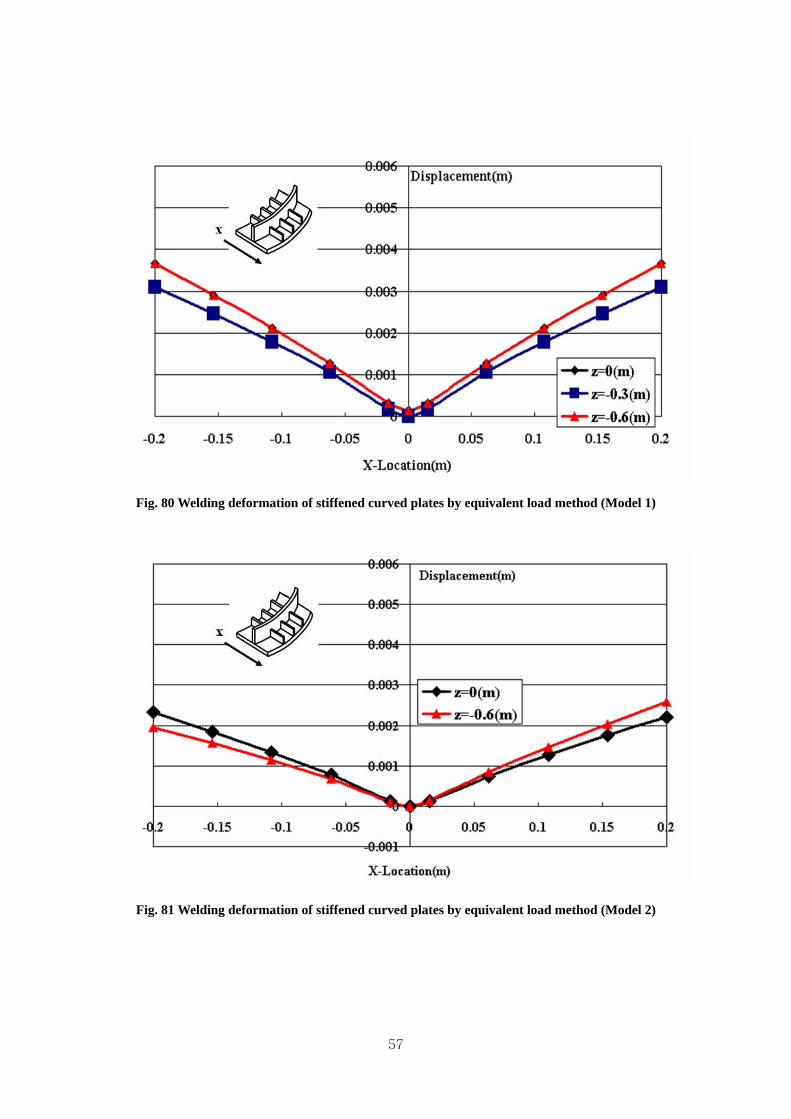
Fig. 80 Welding deformation of stiffened curved plates by equivalent load method (Model 1)
Fig. 81 Welding deformation of stiffened curved plates by equivalent load method (Model 2)
58
Fig. 82 Welding deformation of stiffened curved plates by equivalent load method (Model 3)
Fig. 83 Welding deformation of stiffened curved plates by equivalent load method (Model 4)
59
Fig. 84 Welding deformation of stiffened curved plates by equivalent load method (Model 1)
Fig. 85 Welding deformation of stiffened curved plates by equivalent load method (Model 2)
60
Fig. 86 Welding deformation of stiffened curved plates by equivalent load method (Model 3)
Fig. 87 Welding deformation of stiffened curved plates by equivalent load method (Model 4)
61
7. Comparison of thermal elasto-plastic analysis and equivalent load method of stiffened curved plates The welding deformation (at x=0.2m) calculated by two different methods (EPA: thermal Ealsto-Plastic
Analysis, ELM: Equivalent Load Method) are compared in Table2.
Both results show fairly good agreements with each other within 20% of average difference.
Table. 2 Welding distortion of stiffened curved plate(at x=0.2m)
ELM 0.0037 0.0037 0.0022 0.0026 0.0031 0.0020 0.0025 0.0023
Average
Ratio
Ratio 1.2329 1.2272 1.0465 1.0221 1.2244 1.2661 1.4338 1.1445 1.2080
Fig. 88 Comparison of welding deformation of stiffened curved plates (model 1 & 2)
62
Fig. 89 Comparison of welding deformation of stiffened curved plates (Model 3 & 4)
Fig. 90 Comparison of welding deformation of stiffened curved plates (Model 1 & 2)
Fig. 91 Comparison of welding deformation of stiffened curved plates (Model 3 &4)
63
As shown in Fig. 88-91, Y-direction displacements of stiffened curved plates by thermal elasto-
plastic analysis and equivalent load method are similar. The welding deformation by the equivalent
load method is generally bigger than the welding deformation by the thermal elasto-plastic analysis.
The reason of this tendency is due to the precision to evaluate the degree of restraint of base welding
structure. Based on the welding experiment of stiffened curved plates, more precise degree of restraint
of base welding structure can be evaluated. So, the welding deformation of stiffened curved plate by
the equivalent loads method could give better agreement with the numerical and experimental results of
welding deformation.
64
8. Plan of experiments 8.1. Welding deformation experiment
The welding deformation experiment was performed for four kinds of stiffened curved plates. As
shown in Fig. 92, the experimental models have three kinds of curvatures ( =ρ 1000mm, 2000mm,
and 5000mm). The curvatures were selected by investigating actual fabrication data in the shipyards.
Fig. 92 Size of the experimental models for welding distortion
In order to study the effect of welding sequence on the welding distortion, the experimental model
has two kinds of welding sequences shown in Fig. 93. Case 1 is that the longitudinal stiffener is
welded after all the transverse stiffeners are welded in order. Case 2 is that the longitudinal stiffener
is welded at first and then the transverse stiffeners are welded in order. It is generally known by the
welding experts that the welding deformation of case 2 is smaller than that of case 1.
This fact will be examined and verified by numerical calculation and experiment later in Fig.100 -
107. In many shipyards, however, welding sequence of case 1 has been generally used because of
the productivity. But, in case of some particular ships, if the welding deformation is more critical
than the productivity, the case 2 will be more recommendable.
65
Fig. 93 Two different welding sequences of experimental model
The experimental models were selected by investigating the actual fabrication data in the shipyard.
The 1st and 4th experimental model with =ρ 1000(mm) and =ρ 5000(mm) adopted the welding
sequence of case 1, and the 2nd and 3rd experimental model with =ρ 2000(mm) adopted each
welding sequence of case 1 and 2.
Fig. 94 Four experimental models with welding sequence
66
Fig. 95 Photographs of experimental steels
8.2. Tensile test The experimental model has been constructed using two kinds of steel plates. The one has a
thickness of 16(mm), while the other has a thickness of 9 (mm). The tensile tests for two kinds of
steel plates were performed. Each steel plate is tested three times and the average yield strength and
ultimate strength is used for the numerical calculation.
67
9. Results of experiments 9.1. Tensile test
Fig. 96 Specimens of tensile test
As shown in Fig. 96, two kinds of specimen (thickness=16mm, 9mm) was used for tensile test. In
case of thickness=16(mm), the specimen was fabricated in round bar shape. In case of
thickness=9(mm), the specimen was fabricated in plate shape because of the thin thickness.
Fig. 97 Tensile test of 9(mm) plate
Fig. 98 Tensile test of 16(mm) plate
68
Table. 3 Tensile test result (yield stress)
1st (MPa) 2nd (MPa) 3rd (MPa) Average (MPa)
Thickness 16(mm) 283.6 288.4 289.4 287.1
Thickness 9(mm) 275.4 275.8 279.3 276.8
Fig.97 - 98 show the stress-strain curves of tensile tests of the specimen. In general, 0.2% offset
yield stress has been customary used to determine the yield stress for some other material except
mild steel which has no definite yield stress. However, 1% offset yield stress is adopted here since
sufficient plastic flow at 0.2% offset could not be expected for 9mm specimen shown in Fig.101. But
the difference is very small.
Table 3 shows the yield stresses of two kinds of specimen. The average yield stress is used for
analysis to estimate the welding deformation.
9.2. Welding deformation experiment
Fig. 99 Pictures of welding experiment
Welding expert with more than 20 year’s experience performed the experiment. The welding
speed was checked every 5 seconds that the welding velocity could be kept nearly constant with
69
5(mm/sec). The welding deformation is measured by 3-D digitizer which can measure 3-D position
shown in Fig. 99.
9.3. Comparison of welding deformation between experiment and analysis
Fig. 100 Comparison of welding deformation with R=1000(mm)
70
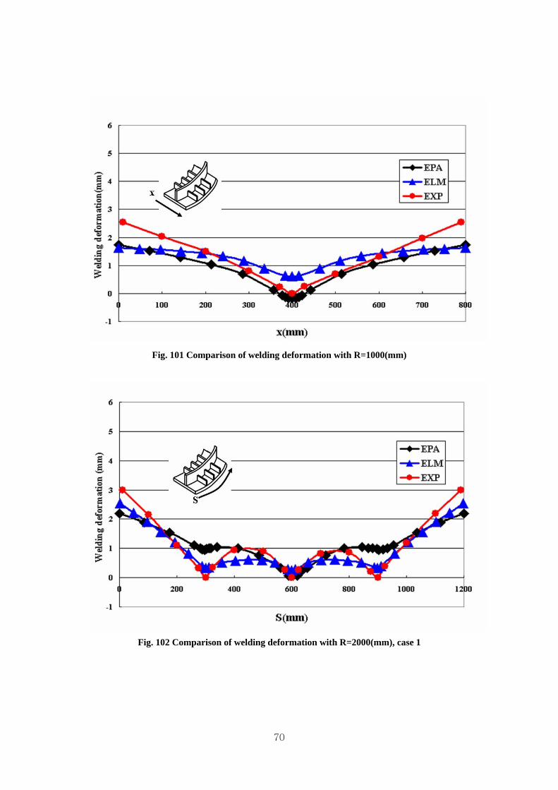
Fig. 101 Comparison of welding deformation with R=1000(mm)
Fig. 102 Comparison of welding deformation with R=2000(mm), case 1
71
Fig. 103 Comparison of welding deformation with R=2000(mm), case 1
Fig. 104 Comparison of welding deformation with R=2000(mm), case 2
72
Fig. 105 Comparison of welding deformation with R=2000(mm), case 2
Fig. 106 Comparison of welding deformation with R=5000(mm)
73
Fig. 107 Comparison of welding deformation with R=5000(mm)
By the analysis results, the welding deformation is getting larger as the radius of curvature
becomes large value, and the welding deformation of case 1 is larger than that of case 2. From this
result, it is recommended that the curved longitudinal stiffener should be welded first before the
smaller transverse stiffeners are welded from the view point of welding distortion control.
The welding deformations by the experiment show fairly good agreements with those by the
ELM(Equivalent Load Mehod) suggested in this paper, but the welding deformation by the
EPA(Thermal Elasto-Plastic Analysis) has a different tendency compared with the cases of ELM and
EXP(Experiment).
In case of ELM and EXP, the deformation at the transverse stiffener has a small value, but in case
of EPA, the deformation at the transverse stiffener has a large value.
74
10. Welding distortion analysis of a stiffened curved panel block by equivalent load method
10.1. Dimension and welding heat input of a curved double bottom block
Fig. 108 Curved double bottom block for analysis
The analysis model has 6 longitudinal stiffeners (Longi) on the surface bottom plate and 6
longitudinal stiffeners on the inner bottom plate. 2 girders and 2 transverse webs between the surface
and inner bottom plate shown in Fig. 108. A curvature of the plate ( ρ ) is 5000(mm) in the
longitudinal direction.
Table. 4 Dimension and welding heat input
Size(mm) Thickness(mm) Heat input(cal/mm)
Surface bottom 8000×7200, ρ=5000 12 -
Inner bottom 8000×7200, ρ=5000 12 -
Girder 8000×1200 12 252
Transverse Web 7200×1200 12 252
Longitudinal Stiff. 8000×200 10 218.4
75
The dimension of the curved double bottom block is shown in Table. 4. The value of the heat input
is determined by considering the data in the shipyards. In this analysis, it is assumed that the voltage
and welding velocity has a constant value with 30(V) and 5(mm/s). The current is controlled for
exact heat input.
Fig. 109 Modeling for finite element analysis
The model of the curved double bottom block has 20864 elements and 20906 nodes. The number
of elements has a large value for elasto-plastic analysis. Actually, the elasto-plastic analysis for this
block is nearly impossible. The ELM, however, is adopting an elastic analysis, so the welding
deformation can be predicted.
In this analysis, the longitudinal direction is x-direction, the transversal direction is y-direction and
the height direction is z-direction as shown in Fig. 109.
76
Fig. 110 Welding sequences
The welding sequence is determined by considering the welding sequence in ship yard. First, the
longitudinal stiffener on the surface and inner bottom is welded as shown in step 1. Second, the
Girder, and transverse web frame is welded in order as shown in step 2 and 3. The inner bottom with
the longitudinals is welded lastly as shown in step 4.
77
10.2. Heat transfer analysis
Fig. 111 Heat transfer analysis
All of the welding process is analyzed through 20 steps and the cooling process is analyzed during
4 steps. Because it is assumed in previous chapter that the temperature history of all section is same,
as shown in Fig. 111, the heat transfer analysis is performed by 2-D thermal analysis. In this case,
because the base plates (surface bottom, inner bottom) have same thickness, and the stiffeners have
two kinds of thickness, the heat transfer analysis is performed twice.
10.3. Calculation of degree of restraint The degree of restraint is calculated by the unit load method as introduced in previous chapter. For
calculating the degree of restraint, it needs to perform two unit load elastic analysis, a free state and a
restrained state.
Fig. 112 Calculation of the restraint of Free State
The experimental result is necessary for calculating the degree of restraint of a free state. As
shown in Fig. 112, by the 2-D heat transfer analysis, the highest temperature is calculated. Because
the inherent strain is determined by the highest temperature and the degree of restraint, if the degree
of restrain is assumed, the welding deformation can be calculated. If the calculated welding
78
deformation is different with the experimental result, changed degree of restraint is used to calculate
the welding deformation. By this loop, the exact degree of restraint of a free state is calculated.
Fig. 113 Calculation of degree of restraint
The degree of restraint of a free state fβ is expressed by the stiffness of bar and plate in bar-
spring model.
statefreeinbarofstiffnessk
statefreeinspringofstiffnesskwhere
kkk
fB
fS
fBfS
fSf
:
:
+=β
Substituting the stiffness by the unit load method in a free state fR , the fSk and fBk is
calculated.
fffSffB
fffBfSffS
RkRk
Rkkk
×−=−=
×=+×=
)1(
)(
β
ββ
Substituting the degree of restraint of restrained state rβ
staterestrainedinbarofstiffnessk
staterestrainedinspringofstiffnesskwhere
kkk
rB
rS
rBrS
rSr
:
:
+=β
In this expression, because the rBk is the stiffness of the heat input area (bar) in restrained state,
the stiffness of spring in restrained state rBk has a same value with the stiffness of spring in free
state fBk . Therefore the stiffness of spring and the stiffness of bar in restrained state are calculated.
79
fBrrBrrS
fBrB
kRkRk
kk
−=−=
=
10.4. Prediction of welding deformation of a curved double bottom block by equivalent load method
The welding deformation by the equivalent load method is shown in Fig. 114 - 116. The analysis
shows that the buckling phenomena (deformation) occurred in surface and inner bottom plate along
the longitudinal direction.
Fig. 114 Welding deformation of curved double bottom block
80
Fig. 115 Welding deformation of curved double bottom block
Fig. 116 Welding deformation of curved double bottom block
81
Fig. 117 Welding deformation in longitudinal direction of surface bottom
Fig. 118 Welding deformation in transversal direction of surface bottom
82
Fig. 119 Welding deformation in longitudinal direction of inner bottom
Fig. 120 Welding deformation in transversal direction of inner bottom
83
The welding deformations in longitudinal direction and transverse direction of surface and inner
bottom plate are shown in Fig 117 - 120. The welding deformation in transverse direction of the
surface bottom plate is convex between the longitudinal stiffeners, and the welding deformation in
transverse direction of the inner bottom plate is concave between the longitudinal stiffeners.
The welding deformation in longitudinal direction of two bottom plate is not simple like the
transverse cases. Because the buckling deformation occurs along the longitudinal direction, the
welding deformation between the transverse webs has shapes of waves. It is thought that the
buckling occurs because of an effect of the rigidity of the curved bottom plate. Because of the
buckling, it is thought that the maximum welding deformation has a small value considering the
block dimension.
The CPU running time is shown in Table. 5. The CPU running time proves the efficiency of the
equivalent load method.
Table. 5 Comparison of computation time
ELM EPA
Analysis time
(Experimental model) 3~4(min) 1.5~2(day)
Analysis time
(Curved double hull block) 30(min) impossible
Pentium Ⅳ: CPU 3.20GHz, 2.00GB RAM, Microsoft Windows XP
84
11. Conclusions
In this research, welding deformation analysis using equivalent load method based on inherent strain
is developed for prediction welding deformation of various hull block shapes including curved hull
block. Developed welding deformation analysis can consider the various modes of welding
deformation such as longitudinal/transverse shrinkage and longitudinal/transversal bending
simultaneously. The analysis can reflect reasonably the change of structural stiffness by considering the
welding sequence according to fabrication stages. Most of all, the efficiency of calculation time and
cost is guaranteed considering the complexity of block shape by the developed analysis. The main
conclusions of this research are summarized as follow:
(1) The welding region, where inherent strain occurs, is idealized as a bar-spring model. The
inherent strain is determined by the thermal elasto-plastic analysis of bar-spring model which has two
variables; highest temperature and the degree of restraint. Therefore, by the heat transfer analysis and
the calculation of the degree of restraint, the distribution of inherent strain around the HAZ was
calculated.
(2) The highest temperature is an important factor with the degree of restraint for calculating
the inherent strain. For calculating the highest temperature, 2-D heat transfer analysis was performed.
Actually, a phenomenon of heat transfer is a 3-dimensional phenomenon, but for the case with the long
welding line like a ship hull block, it can be assume that the temperature transition of the welding edge
area and the heat transfer to another stiffener is neglected. The 2-D heat transfer analysis, therefore,
represented the welding heat transfer well.
(3) The degree of restraint is one of the important factors for calculating the inherent strain.
The unit load method is used to calculate the degree of restraint. By the experiment, exact degree of
restraint of curved plate is calculated at a free state. To reflect the change of structural stiffness
according to the fabrication stages, two unit load elastic analysis, a free state and a restrained state, was
performed.
(4) The inherent strain which is given by the 2-D heat transfer analysis and the unit load
analysis was used to calculate the equivalent loads. The equivalent loads (axial force and moment) are
calculated by integration of the inherent strain. The elastic analysis was performed to predict welding
deformation by applying the equivalent loads.
85
(5) The welding experiment of the curved stiffened plate with different curvature and welding
sequence was performed. The welding deformations by the equivalent load method, thermal elasto-
plastic analysis and experiment are compared to prove the accuracy of the equivalent load method. The
welding deformation by the equivalent load method has better agreement to the welding experiment
compare with the welding deformation by the thermal elasto-plastic analysis. The equivalent load
method is more precise and more effective than the elasto-plastic analysis..
(6) An efficiency of the equivalent load method is proved by predicting a welding
deformation of curved double bottom block. Since it only requires experimental data of simple
specimen, the equivalent load method can be utilized in the estimation of welding deformation of
curved blocks which has more complex shapes.
(7) The most important merit by the equivalent load method is the efficiency to calculate the
welding deformation. As shown in Table 5, the CPU running time proves the efficiency of the
equivalent load method.
The welding deformation analysis by the equivalent load method can be applied to the design stage,
so it can be utilized to decide exact margin. Furthermore, it is useful to minimize the welding
deformation by controlling the welding condition and the welding sequence.
86
12. Acknowledgements
The authors would like to express our sincere gratitudes to Mr. Glenn M. Ashe, American Bureau of
Shipping and all of the members of the Project Technical Committee for their supports. We also would
like to thank Dr. Myoung Soo Han and Mr. Hyun Wook Kim, Deawoo Shipbuilding and Marine
Engineering, Co., Ltd, for their supports to provide the facilities and conveniences for the welding
distortion experiments in Okpo shipyard.
87
13. References
(1) Watanabe, M. and Satoh, K. (1965) “Welding mechanics and its applications.” Asakura Publication,
pp. 367-411
(2) Masubuchi, K. (1980) “Analysis of welded structures.”Pergamon Press, pp. 239-243
(3) Tekriwal, P. (1989) “Three-dimensional transient thermo-elasto-plastic modeling of gas metal arc
welding using the finite element method.” U. of Illinois at Urbana-Champaign, Urbana, Ill., USA
(4) Ueda, Y. and Ma, N.X. (1995) “Measuring Methods of Three-Dimensional Residual Stresses with
Aid of Distribution Function of Inherent Strains(Report3).” Trans. of Japanese Welding Research
Institute, 24(2), pp. 123-130
(5) Jang, C.D. and Seo, S.I. (1996) “A study on the automatic fabrication of welded built-up beams.”
Trans. of the Society of Naval Architects of Korea, 33(1), pp. 206-213
(6) Jang, C.D., Seo, S.I. and Ko, D.E. (1997) “A Study on the Prediction of Deformations of Plates Due
to Line Heating Using a Simplified Thermal Elasto-Plastic Analysis” Journal of Ship Production,
Vol.13, No.1, pp.22-27
(7) Kim, S.I., Han, J.M., Cho, Y.K., Kang, J.K. and Lee, J.Y. (1997) “A study on the accuracy control
of block assembly in shipbuilding.” ICCAS ’97, pp. 367-381
(8) Murakawa, H., Luo, Y. and Ueda, Y. (1997) “Prediction of welding deformation and residual stress
by elastic FEM based on inherent strain” J. of the society of naval architects of Japan, 180, pp. 739-
751
(9) Jang, C.D., Moon, S.C. (1998) “An Algorithm to Determine Heating Lines for Plate Forming by
Line Heating Method” Journal of Ship Production, Vol.14, No.4, pp.238-245
(10) Jang, C.D. and Lee, C.H. (1999) “Prediction of Welding Deformation of Stiffened Plates using
inherent Strain Method” Proceedings of the Thirteenth Asian Technical Exchange and Advisory
Meeting on Marine Structures, pp. 485-492
(11) Seo, S.I. and Jang, C.D. (1999) “A study on the prediction of deformations of welded ship
structures.” Journal of Ship Production, 15(2), pp. 73-81
(12) Jang, C.D., Moon, S.C. and Ko, D.E. (2000) “Acquisition of Line Heating Information for
Automatic Plate Forming” Proc. Ship Structure Symposium, SSC, SNAME
(13) Seo, S.I., Yang, Y.H. and Jang, C.D. (2001) "Development of a New Finite-Element Analysis of
Deformation of Plate Due to Line Heating" Journal of Ship Production, Vol. 17, No. 1, pp. 1-7
(14) Jang, C.D., Kim, H.K. and Song, H.C. (2002) "Optimum Structural Design of the High Speed
Surface Effect Ships built of Composite Materials" Journal of Marine Technology, Vol. 38, No. 4
(15) Jang, C.D., Lee, C.H. and Ko, D.E. (2002) “Prediction of welding deformations of stiffened
panels” Journal of Engineering for the Maritime Environment, Vol. 216, No. M2, pp. 133-143
(16) Jang, C.D., Ha, Y.S., and Ko, D.E. (2003) "An Improved Inherent Strain Analysis for the
88
Prediction of Plate Deformations Induced by Line Heating Considering Phase Transformation of
Steel" Proc. of 13th ISOPE
(17) Jang, C.D. and Lee, C.H. (2003) "Prediction of Welding Deformations of Ship Hull Blocks"
Journal of Ship and Ocean Technology, Vol. 7, No. 4, pp. 41-49
(18) Jang, C.D., Ryu, H.S. and Lee, C.H. (2004) "Prediction and Control of Welding Deformations in
Stiffened Hull Blocks using Inherent Strain Approach" Proc. of 14th ISOPE, Vol. IV, pp.159-165
(19) Jang, C.D., Kim, T.H., Ko, D.E., Thomas Lamb and Ha, Y.S. (2005) "Prediction of steel plate
deformation due to triangle heating using the inherent strain method." Journal of Marine Technology,
Vol. 10, No. 4
(20) Jang, C.D., Ha, Y.S. and Kim, Y.T. (2006) “Determination of optimal heating conditions in line
heating process with weaving motions.” Proc. Of 16th ISOPE, pp. 182~186
(21) Jang, C.D., Nomoto, T., Ko, D.E., Ryu, H.S. and Ha, Y.S. (2006) “Simulation of post welding
distortion control of stiffened hull blocks by line heating.” Journal of Ship Research, Vol. 50, No. 3,
pp. 268~277
PROJECT TECHNICAL COMMITTEE MEMBERS The following persons were members of the committee that represented the Ship Structure Committee to the Contractor as resident subject matter experts. As such they performed technical review of the initial proposals to select the contractor, advised the contractor in cognizant matters pertaining to the contract of which the agencies were aware, performed technical review of the work in progress and edited the final report.
Chairman
Members Contracting Officer’s Technical Representative: Marine Board Liaison: Executive Director Ship Structure Committee:
SHIP STRUCTURE COMMITTEE LIAISON MEMBERS
LIAISON MEMBERS American Iron and Steel Institute Mr. Alexander Wilson American Society for Testing & Materials Captain Charles Piersall (Ret.) American Society of Naval Engineers Captain Dennis K. Kruse (USN Ret.) American Welding Society Mr. Richard Frank Bath Iron Works Mr. Steve Tarpy Canada Ctr for Minerals & Energy Technology Dr. William R. Tyson Colorado School of Mines Dr. Stephen Liu Edison Welding Institute Mr. Rich Green International Maritime Organization Mr. Igor M. Ponomarev Int’l Ship and Offshore Structure Congress Dr. Jack Spencer INTERTANKO Mr. Dragos Rauta Massachusetts Institute of Technology Memorial University of Newfoundland Dr. M. R. Haddara National Cargo Bureau Captain Jim McNamara Office of Naval Research Dr. Yapa Rajapaksie Oil Companies International Maritime Forum Mr. Phillip Murphy Tanker Structure Cooperative Forum Technical University of Nova Scotia Dr. C. Hsiung United States Coast Guard Academy Commander Kurt Colella United States Merchant Marine Academy Dr. C. B. Kim United States Naval Academy Dr. Ramswar Bhattacharyya University of British Columbia Dr. S. Calisal University of California Berkeley Dr. Robert Bea University of Houston - Composites Eng & Appl. Dr. Jerry Williams University of Maryland Dr. Bilal Ayyub University of Michigan Dr. Michael Bernitsas University of Waterloo Dr. J. Roorda Virginia Polytechnic and State Institute Dr. Alan Brown Webb Institute Prof. Roger Compton Welding Research Council Dr. Martin Prager Worchester Polytechnic Institute Dr. Nick Dembsey Samsung Heavy Industries, Inc. Dr. Satish Kumar
RECENT SHIP STRUCTURE COMMITTEE PUBLICATIONS
Ship Structure Committee Publications on the Web - All reports from SSC 1 to current are available to be downloaded from the Ship Structure Committee Web Site at URL:
http://www.shipstructure.org SSC 445 – SSC 393 are available on the SSC CD-ROM Library. Visit the National Technical Information Service (NTIS) Web Site for ordering hard copies of all SSC research reports at
URL: http://www.ntis.gov
SSC Report Number Report Bibliography SSC 452 Aluminum Structure Design and Fabrication Guide, Sielski R. 2007 SSC 451 Mechanical Collapse Testing On Aluminum Stiffened Panels For Marine
Jones L.M, Jr. 2007 SSC 449 Hydrodynamic Pressures and Impact Loads for High Speed
Catamaran/SES, Vorus W. 2007 SSC 448 Fracture Mechanics Characterization of Aluminum Alloys for Marine
Structural Applications, Donald J.K., Blair A. 2007 SSC 447 Fatigue and Fracture Behavior of Fusion and Friction Stir Welded
Aluminum Components, Kramer R. 2007 SSC 446 Comparative Study of Naval and Commercial Ship Structure Design
Standards, Kendrick, A., Daley C. 2007 SSC 450 Ship Structure Committee: Effectiveness Survey SSC 449 Hydrodynamic Pressures and Impact Loads for High Speed Catamaran /
SES SSC 448 Fracture Mechanics Characterization of Aluminum Alloys for Marine
Structural Applications SSC 447 Fatigue and Fracture Behavior of Fusion and Friction Stir Welded
Aluminum Components SSC 446 Comparative Study of Naval and Commercial Ship Structure Design
Standards SSC 445 Structural Survivability of Modern Liners, Iversen R. 2005 SSC 444 In-Service Non-Destructive Estimation of the Remaining Fatigue Life of