90
Conferencing and Instant Messaging Planning and Installation Guide ShoreTel 13.1 November 2012
Conferencing and Instant MessagingPlanning and Installation Guide
ShoreTel 13.1
November 2012
Legal Notices
ShoreTel 13.1 Planning and Installation Guide 2
Document and Software Copyrights
Copyright © 1998-2012 by ShoreTel Inc., Sunnyvale, California, USA. All rights reserved.
Printed in the United States of America. Contents of this publication may not be reproduced or transmitted in any form or by any means, electronic or mechanical, for any purpose, without prior written authorization of ShoreTel, Inc. ShoreTel, Inc. reserves the right to make changes without notice to the specifications and materials contained herein and shall not be responsible for any damage (including consequential) caused by reliance on the materials presented, including, but not limited to typographical, arithmetic or listing errors.
Trademarks
ShoreTel, ShoreTel (and logo), Brilliantly Simple, Brilliantly Simple Communication, ShoreGear, ShorePhone, and ShoreWare are registered trademarks of ShoreTel, Inc. in the United States and/or other countries. The ShoreTel logo is a trademark of ShoreTel, Inc. in the United States and/or other countries.
All other copyrights and trademarks herein are the property of their respective owners.
Version Information
ShoreTel 13.1 Conferencing & Instant Messaging Planning and Installation GuideDocument Part Number: 850-1297-01Version: CIMPIG_13.1_20121114Date: November 14, 2012
Patents
The ShoreTel System is covered by patents as listed at http://www.shoretel.com/about/patents.html.
Company Information
ShoreTel, Inc.960 Stewart DriveSunnyvale, California 94085 USA+1.408.331.3300+1.408.331.3333 (fax)www.shoretel.com
Contents
Objectives . . . . . . . . . . . . . . . . . . . . . . . . . . . . . . . . . . . . . . . . . . . . . . . . . . . . . . . . . . . . . . . . . 6Audience . . . . . . . . . . . . . . . . . . . . . . . . . . . . . . . . . . . . . . . . . . . . . . . . . . . . . . . . . . . . . . . . . . 6Organization . . . . . . . . . . . . . . . . . . . . . . . . . . . . . . . . . . . . . . . . . . . . . . . . . . . . . . . . . . . . . . . . 6Documentation Overview . . . . . . . . . . . . . . . . . . . . . . . . . . . . . . . . . . . . . . . . . . . . . . . . . . . . . . 6
System Documentation . . . . . . . . . . . . . . . . . . . . . . . . . . . . . . . . . . . . . . . . . . . . . . . . . . . . 7Hardware Documentation . . . . . . . . . . . . . . . . . . . . . . . . . . . . . . . . . . . . . . . . . . . . . . . . . . 7User Documentation . . . . . . . . . . . . . . . . . . . . . . . . . . . . . . . . . . . . . . . . . . . . . . . . . . . . . . 7Release Notes . . . . . . . . . . . . . . . . . . . . . . . . . . . . . . . . . . . . . . . . . . . . . . . . . . . . . . . . . . . 7Online Knowledge Base . . . . . . . . . . . . . . . . . . . . . . . . . . . . . . . . . . . . . . . . . . . . . . . . . . . 8
Document Conventions . . . . . . . . . . . . . . . . . . . . . . . . . . . . . . . . . . . . . . . . . . . . . . . . . . . . . . . 8
Chapter 1 Conferencing & Instant Messaging Overview . . . . . . . . . . . . . . . . . . . . . . . .9
About the ShoreTel Service Appliance . . . . . . . . . . . . . . . . . . . . . . . . . . . . . . . . . . . . . . . . . . 10Service Appliance 400 (SA-400) . . . . . . . . . . . . . . . . . . . . . . . . . . . . . . . . . . . . . . . . . . . . . . . 10
SA-400 Key Features . . . . . . . . . . . . . . . . . . . . . . . . . . . . . . . . . . . . . . . . . . . . . . . . . . . . 11Distributed Conferencing Capabilities . . . . . . . . . . . . . . . . . . . . . . . . . . . . . . . . . . . . . . . . . . . 11Single System Management . . . . . . . . . . . . . . . . . . . . . . . . . . . . . . . . . . . . . . . . . . . . . . . . . . 11Integrated Services . . . . . . . . . . . . . . . . . . . . . . . . . . . . . . . . . . . . . . . . . . . . . . . . . . . . . . . . . 12
Audio Conferences . . . . . . . . . . . . . . . . . . . . . . . . . . . . . . . . . . . . . . . . . . . . . . . . . . . . . . 12Instant Messaging Service . . . . . . . . . . . . . . . . . . . . . . . . . . . . . . . . . . . . . . . . . . . . . . . . 13
Single Dial-in Number and Web Address . . . . . . . . . . . . . . . . . . . . . . . . . . . . . . . . . . . . . . . . 13Service Appliance Failover . . . . . . . . . . . . . . . . . . . . . . . . . . . . . . . . . . . . . . . . . . . . . . . . . . . 13
Complete Failure Scenario . . . . . . . . . . . . . . . . . . . . . . . . . . . . . . . . . . . . . . . . . . . . . . . . 14Conferencing and Instant Messaging Resiliency . . . . . . . . . . . . . . . . . . . . . . . . . . . . . . . 14
Service Appliance Logs and Records . . . . . . . . . . . . . . . . . . . . . . . . . . . . . . . . . . . . . . . . . . . 15Integration with ShoreTel Communicator and Microsoft Outlook . . . . . . . . . . . . . . . . . . . . . . . 15Host and Participant Desktop Requirements . . . . . . . . . . . . . . . . . . . . . . . . . . . . . . . . . . . . . . 15
Internet Browsers . . . . . . . . . . . . . . . . . . . . . . . . . . . . . . . . . . . . . . . . . . . . . . . . . . . . . . . 15Microsoft Outlook Integration . . . . . . . . . . . . . . . . . . . . . . . . . . . . . . . . . . . . . . . . . . . . . . 16Microsoft PowerPoint Support . . . . . . . . . . . . . . . . . . . . . . . . . . . . . . . . . . . . . . . . . . . . . . 16
Chapter 2 Planning and System Design. . . . . . . . . . . . . . . . . . . . . . . . . . . . . . . . . . . . .17
Recommendations . . . . . . . . . . . . . . . . . . . . . . . . . . . . . . . . . . . . . . . . . . . . . . . . . . . . . . . . . . 18Determining Your Conferencing Needs . . . . . . . . . . . . . . . . . . . . . . . . . . . . . . . . . . . . . . . . . . 18
Determining the Number of Service Appliances to Deploy . . . . . . . . . . . . . . . . . . . . . . . . 18System Topology . . . . . . . . . . . . . . . . . . . . . . . . . . . . . . . . . . . . . . . . . . . . . . . . . . . . . . . . 19Load Balancing . . . . . . . . . . . . . . . . . . . . . . . . . . . . . . . . . . . . . . . . . . . . . . . . . . . . . . . . . 20
ShoreTel 13.1 Conferencing and Instant Messaging 3
Table of Contents
Redundancy . . . . . . . . . . . . . . . . . . . . . . . . . . . . . . . . . . . . . . . . . . . . . . . . . . . . . . . . . . . 20Licensing Requirements . . . . . . . . . . . . . . . . . . . . . . . . . . . . . . . . . . . . . . . . . . . . . . . . . . . . . 20
Chapter 3 Network Requirements and Preparation . . . . . . . . . . . . . . . . . . . . . . . . . . .22
Network Requirements . . . . . . . . . . . . . . . . . . . . . . . . . . . . . . . . . . . . . . . . . . . . . . . . . . . . . . 23Supported Codecs and Bandwidth . . . . . . . . . . . . . . . . . . . . . . . . . . . . . . . . . . . . . . . . . . 23
Network Bandwidth Requirements for Web Conference Sessions . . . . . . . . . . . . . . . . . . . . . 24IP Addressing . . . . . . . . . . . . . . . . . . . . . . . . . . . . . . . . . . . . . . . . . . . . . . . . . . . . . . . . . . . . . . 25Time Services . . . . . . . . . . . . . . . . . . . . . . . . . . . . . . . . . . . . . . . . . . . . . . . . . . . . . . . . . . . . . 25Network Security . . . . . . . . . . . . . . . . . . . . . . . . . . . . . . . . . . . . . . . . . . . . . . . . . . . . . . . . . . . 25
Internal Firewall . . . . . . . . . . . . . . . . . . . . . . . . . . . . . . . . . . . . . . . . . . . . . . . . . . . . . . . . . 25Security Considerations . . . . . . . . . . . . . . . . . . . . . . . . . . . . . . . . . . . . . . . . . . . . . . . . . . 26
Deployment Scenarios . . . . . . . . . . . . . . . . . . . . . . . . . . . . . . . . . . . . . . . . . . . . . . . . . . . . . . . 26Deploying a Service Appliance in the LAN . . . . . . . . . . . . . . . . . . . . . . . . . . . . . . . . . . . . 26Deploying a Service Appliance In the DMZ . . . . . . . . . . . . . . . . . . . . . . . . . . . . . . . . . . . . 27Best Practice Tests . . . . . . . . . . . . . . . . . . . . . . . . . . . . . . . . . . . . . . . . . . . . . . . . . . . . . . 30
Chapter 4 Site Requirements and Preparation . . . . . . . . . . . . . . . . . . . . . . . . . . . . . . .31
Recommendations . . . . . . . . . . . . . . . . . . . . . . . . . . . . . . . . . . . . . . . . . . . . . . . . . . . . . . . . . . 32Specifications . . . . . . . . . . . . . . . . . . . . . . . . . . . . . . . . . . . . . . . . . . . . . . . . . . . . . . . . . . . . . . 32
SA-100 Specifications . . . . . . . . . . . . . . . . . . . . . . . . . . . . . . . . . . . . . . . . . . . . . . . . . . . . 33SA-400 Specifications . . . . . . . . . . . . . . . . . . . . . . . . . . . . . . . . . . . . . . . . . . . . . . . . . . . . 36
Environmental Requirements . . . . . . . . . . . . . . . . . . . . . . . . . . . . . . . . . . . . . . . . . . . . . . . . . . 37
Chapter 5 Installing Service Appliances . . . . . . . . . . . . . . . . . . . . . . . . . . . . . . . . . . . .38
Preparing for Installation . . . . . . . . . . . . . . . . . . . . . . . . . . . . . . . . . . . . . . . . . . . . . . . . . . . . . 39Verifying the Contents of the Box . . . . . . . . . . . . . . . . . . . . . . . . . . . . . . . . . . . . . . . . . . . . . . 39Location Guidelines . . . . . . . . . . . . . . . . . . . . . . . . . . . . . . . . . . . . . . . . . . . . . . . . . . . . . . . . . 40Installation . . . . . . . . . . . . . . . . . . . . . . . . . . . . . . . . . . . . . . . . . . . . . . . . . . . . . . . . . . . . . . . . 40
Mounting the ShoreTel Service Appliance . . . . . . . . . . . . . . . . . . . . . . . . . . . . . . . . . . . . 40Connecting the AC Power to the SA-100 . . . . . . . . . . . . . . . . . . . . . . . . . . . . . . . . . . . . . 40Connecting AC Power to the SA-400 . . . . . . . . . . . . . . . . . . . . . . . . . . . . . . . . . . . . . . . . 41
Setting the IP Address Manually . . . . . . . . . . . . . . . . . . . . . . . . . . . . . . . . . . . . . . . . . . . . . . . 42Using DHCP to Set the IP Address . . . . . . . . . . . . . . . . . . . . . . . . . . . . . . . . . . . . . . . . . . . . . 44
Connecting the Service Appliance to the Network . . . . . . . . . . . . . . . . . . . . . . . . . . . . . . 44Installing the Bezel . . . . . . . . . . . . . . . . . . . . . . . . . . . . . . . . . . . . . . . . . . . . . . . . . . . . . . . . . . 45Configuring the Unit for Operation . . . . . . . . . . . . . . . . . . . . . . . . . . . . . . . . . . . . . . . . . . . . . . 46
Chapter 6 Configuring the Service Appliance . . . . . . . . . . . . . . . . . . . . . . . . . . . . . . . .47
Upgrading the Firmware . . . . . . . . . . . . . . . . . . . . . . . . . . . . . . . . . . . . . . . . . . . . . . . . . . . . . 48Service Appliance Configuration Process . . . . . . . . . . . . . . . . . . . . . . . . . . . . . . . . . . . . . . . . 48Configuring the Network Time Protocol (NTP) Server . . . . . . . . . . . . . . . . . . . . . . . . . . . . . . . 49Installing Licenses . . . . . . . . . . . . . . . . . . . . . . . . . . . . . . . . . . . . . . . . . . . . . . . . . . . . . . . . . . 49
Obtaining Conference Licenses . . . . . . . . . . . . . . . . . . . . . . . . . . . . . . . . . . . . . . . . . . . . 49Installing the Licenses . . . . . . . . . . . . . . . . . . . . . . . . . . . . . . . . . . . . . . . . . . . . . . . . . . . . 50
Configuring a Conference Extension . . . . . . . . . . . . . . . . . . . . . . . . . . . . . . . . . . . . . . . . . . . . 50
ShoreTel 13.1 Conferencing and Instant Messaging 4
Table of Contents
Turning Off Port 5004 . . . . . . . . . . . . . . . . . . . . . . . . . . . . . . . . . . . . . . . . . . . . . . . . . . . . . . . 52Setting up the ShoreTel System . . . . . . . . . . . . . . . . . . . . . . . . . . . . . . . . . . . . . . . . . . . . . . . 52
Adding a Service Appliance to the ShoreTel Site . . . . . . . . . . . . . . . . . . . . . . . . . . . . . . . 52Verifying Date and Time Synchronization . . . . . . . . . . . . . . . . . . . . . . . . . . . . . . . . . . . . . 54Configuring a Service Appliance in the DMZ . . . . . . . . . . . . . . . . . . . . . . . . . . . . . . . . . . . 54Configuring a Backup Service Appliance for the Headquarters Server . . . . . . . . . . . . . . . 54Setting Up a Service Appliance to Remote Service Appliances . . . . . . . . . . . . . . . . . . . . 55
Configuring the Conference Viewer Page . . . . . . . . . . . . . . . . . . . . . . . . . . . . . . . . . . . . . . . . 56Configuring the Client Interface . . . . . . . . . . . . . . . . . . . . . . . . . . . . . . . . . . . . . . . . . . . . . . . . 58Configuring HTTPS . . . . . . . . . . . . . . . . . . . . . . . . . . . . . . . . . . . . . . . . . . . . . . . . . . . . . . . . . 59
Obtaining an SSL Certificate . . . . . . . . . . . . . . . . . . . . . . . . . . . . . . . . . . . . . . . . . . . . . . . 59Uploading an HTTPS Certificate . . . . . . . . . . . . . . . . . . . . . . . . . . . . . . . . . . . . . . . . . . . . 60Enabling HTTPS . . . . . . . . . . . . . . . . . . . . . . . . . . . . . . . . . . . . . . . . . . . . . . . . . . . . . . . . 61Using the Firefox Browser . . . . . . . . . . . . . . . . . . . . . . . . . . . . . . . . . . . . . . . . . . . . . . . . . 62
Creating Users . . . . . . . . . . . . . . . . . . . . . . . . . . . . . . . . . . . . . . . . . . . . . . . . . . . . . . . . . . . . . 63Configuring Instant Messaging . . . . . . . . . . . . . . . . . . . . . . . . . . . . . . . . . . . . . . . . . . . . . . . . 63
Enabling Instant Messaging . . . . . . . . . . . . . . . . . . . . . . . . . . . . . . . . . . . . . . . . . . . . . . . 63Configuring the IM Class of Service . . . . . . . . . . . . . . . . . . . . . . . . . . . . . . . . . . . . . . . . . 64Configuring IM . . . . . . . . . . . . . . . . . . . . . . . . . . . . . . . . . . . . . . . . . . . . . . . . . . . . . . . . . . 64Migrating IM and Presence Users to a Service Appliance . . . . . . . . . . . . . . . . . . . . . . . . 65
Connecting with the Microsoft Exchange Server . . . . . . . . . . . . . . . . . . . . . . . . . . . . . . . . . . . 65Enforced Scheduling . . . . . . . . . . . . . . . . . . . . . . . . . . . . . . . . . . . . . . . . . . . . . . . . . . . . . 66Enabling the ShoreTel Connector to Microsoft Exchange . . . . . . . . . . . . . . . . . . . . . . . . . 66Monitoring the Exchange Connector . . . . . . . . . . . . . . . . . . . . . . . . . . . . . . . . . . . . . . . . . 68
Conference Administration Interface . . . . . . . . . . . . . . . . . . . . . . . . . . . . . . . . . . . . . . . . . . . . 68Conferences . . . . . . . . . . . . . . . . . . . . . . . . . . . . . . . . . . . . . . . . . . . . . . . . . . . . . . . . . . . . . . . 69
Reports . . . . . . . . . . . . . . . . . . . . . . . . . . . . . . . . . . . . . . . . . . . . . . . . . . . . . . . . . . . . . . . 69
Chapter 7 Maintenance . . . . . . . . . . . . . . . . . . . . . . . . . . . . . . . . . . . . . . . . . . . . . . . . . .72
Quick Look . . . . . . . . . . . . . . . . . . . . . . . . . . . . . . . . . . . . . . . . . . . . . . . . . . . . . . . . . . . . . . . . 73Viewing Maintenance Information . . . . . . . . . . . . . . . . . . . . . . . . . . . . . . . . . . . . . . . . . . . 73Viewing System Information . . . . . . . . . . . . . . . . . . . . . . . . . . . . . . . . . . . . . . . . . . . . . . . 74Viewing Maintenance Information for a Service Appliance . . . . . . . . . . . . . . . . . . . . . . . . 76Viewing Current Conference Activity Information . . . . . . . . . . . . . . . . . . . . . . . . . . . . . . . 78
Viewing Switch Connectivity . . . . . . . . . . . . . . . . . . . . . . . . . . . . . . . . . . . . . . . . . . . . . . . . . . 79Viewing Audio and Web Conferencing Activity . . . . . . . . . . . . . . . . . . . . . . . . . . . . . . . . . . . . 80Viewing the IM Servers Maintenance Summary . . . . . . . . . . . . . . . . . . . . . . . . . . . . . . . . . . . 81
Chapter 8 Going Live and Training. . . . . . . . . . . . . . . . . . . . . . . . . . . . . . . . . . . . . . . . .83
Complete Operational Testing of Service Appliances . . . . . . . . . . . . . . . . . . . . . . . . . . . . . . . 84Assign Users to Each Service Appliance . . . . . . . . . . . . . . . . . . . . . . . . . . . . . . . . . . . . . . . . . 85Verify Licensing . . . . . . . . . . . . . . . . . . . . . . . . . . . . . . . . . . . . . . . . . . . . . . . . . . . . . . . . . . . . 85Distribute User Guides . . . . . . . . . . . . . . . . . . . . . . . . . . . . . . . . . . . . . . . . . . . . . . . . . . . . . . . 85Training . . . . . . . . . . . . . . . . . . . . . . . . . . . . . . . . . . . . . . . . . . . . . . . . . . . . . . . . . . . . . . . . . . 85
Chapter 9 Backup and Restore . . . . . . . . . . . . . . . . . . . . . . . . . . . . . . . . . . . . . . . . . . . .87
Service Appliance Backup . . . . . . . . . . . . . . . . . . . . . . . . . . . . . . . . . . . . . . . . . . . . . . . . . . . . 88Service Appliance Restore . . . . . . . . . . . . . . . . . . . . . . . . . . . . . . . . . . . . . . . . . . . . . . . . . . . . 90
ShoreTel 13.1 Conferencing and Instant Messaging 5
Preface
This Preface provides an overview of the Conferencing and Instant Messaging Planning and Installation Guide.
Objectives
This document provides planning, installation, and administration information for ShoreTel Service Appliances (SA-100 and SA-400), as well as the following services:
Audio Conferencing
Web Conferencing
Instant Messaging
Audience
This guide is for the person who plans, installs, administers, and maintains the ShoreTel system. This individual should be knowledgeable about data networking and telephony to use this guide effectively.
Organization
This document is generally organized into major tasks, presented in the order in which they should be completed.
Documentation Overview
The ShoreTel system is documented as described in the following sections.
ShoreTel 13.1 Conferencing and Instant Messaging 6
Preface System Documentation
System Documentation
The following system documents are in the documentation folder on the ShoreTel DVD and can also be accessed from ShoreTel Director:
ShoreTel Planning and Installation Guide provides information on how to plan the implementation of the ShoreTel 13 system, as well as how to install the necessary hardware, data communications, and telecommunications elements.
ShoreTel System Administration Guide (this guide) provides detailed information on how to administer and maintain the ShoreTel system using ShoreTel Director. This includes task-based information, as well as screen-by-screen information regarding ShoreTel Director.
Hardware Documentation
The following hardware installation documents are packaged with their associated ShoreTel voice switch or ShoreTel IP phone and appliances:
ShoreTel Voice Switch Quick Install Guide
ShoreTel IP Phone Quick Install Guide
If the system includes the ShoreTel Enterprise Contact Center Solution, refer to the ShoreTel Enterprise Contact Center Solution Administration Guide and the ShoreTel Enterprise Contact Center Solution Planning and Installation Guide.
User Documentation
The following end-user documentation is available both on the ShoreTel web site and through links in ShoreTel Director:
ShoreTel Conferencing User Guide
Telephone User Interface Guides
Telephone Quick Install Guides
Quick Reference Guides
ShoreTel Communicator User Guide (also available as online help in ShoreTel Communicator)
Release Notes
The ShoreTel Server Software Release Notes provide information about new releases and new features as well as issues that relate to new installations and upgrades. This document resides in the documentation folder on the associated DVD and can also be accessed from ShoreTel Director.
ShoreTel 13.1 Conferencing and Instant Messaging 7
Preface Online Knowledge Base
Online Knowledge Base
To access additional information or to resolve issues on ShoreTel Director, you can use the ShoreTel Technical Knowledge base, accessible from the ShoreTel web site at www.shoretel.com.
Document Conventions
The following conventions are used in this guide:
Data-entry fields, hypertext links, control buttons, keywords, and other items within the system management interface are in a boldface font.
Information that you enter in data fields are in a data_entry font.
ShoreTel 13.1 Conferencing and Instant Messaging 8
CHAPTER
1. Conferencing & InstantMessaging Overview
This document is designed for planners and system administrators looking to deploy ShoreTel® Service Appliances in their ShoreTel system to perform conferencing and instant message services.
The Service Appliance installs on your network and augments the ShoreTel system with conferencing and instant messaging services. These services give ShoreTel system users the ability to create and participate in scheduled and impromptu media-rich conferences and to send and receive instant messages. Service Appliances support audio and web conferences and allow Microsoft® Outlook® to schedule conferences.
This chapter presents an overview of the ShoreTel Service Appliance, including a description of the integrated applications and capacities to guide you in planning your installation. Topics discussed in this chapter include:
About the ShoreTel Service Appliance...................................................................... 10
Service Appliance 400 (SA-400) ............................................................................... 10
Distributed Conferencing Capabilities ....................................................................... 11
Single System Management ..................................................................................... 11
Integrated Services ................................................................................................... 12
Single Dial-in Number and Web Address.................................................................. 13
Single Dial-in Number and Web Address.................................................................. 13
Service Appliance Failover........................................................................................ 13
Service Appliance Logs and Records ....................................................................... 15
Integration with ShoreTel Communicator and Microsoft Outlook .............................. 15
Host and Participant Desktop Requirements ............................................................ 15
ShoreTel 13.1 Conferencing and Instant Messaging 9
Conferencing & Instant Messaging Overview About the ShoreTel Service Appliance1
About the ShoreTel Service Appliance
The ShoreTel Service Appliance is a 1U, dedicated, plug-and-play appliance designed to integrate seamlessly into the ShoreTel system and to install where you need it on your network to provide cost-effective conferencing and instant messaging (IM) services for ShoreTel system users.
The 1U footprint means the unit is suitable for 19-inch equipment racks. It is shipped with a versatile rack-mounting kit that easily accommodates different rack styles and a locking ShoreTel front bezel.
The Service Appliance is a node that installs on a ShoreTel server site and performs processing functions for conference calls and IM sessions. In conference calls, the Service Appliance serves as a hub that receives audio and data streams from the participants, bundles the streams, and broadcasts the bundles to the other conference participants. The Service Appliance also maintains conference web pages and manages IM sessions for users.
ShoreTel Telephony Management Service (TMS) and other ShoreTel software installed on the Service Appliance ensure the integration of the unit into the ShoreTel system. This allows the system to use a universal conference number while directing conference requests to the appropriate appliance in environments where two or more Service Appliances are installed. The software also allows the system to collect and store call data from the Service Appliance where it can be retrieved and viewed as Call Detail Records (CDR) in ShoreTel Director.
The conferencing and instant messaging services the Service Appliance provide seamlessly integrate with user desktop applications such as ShoreTel Communicator and Microsoft Outlook.
Service Appliance 400 (SA-400)
The SA-400 has the following characteristics:
Sealed appliance.
Optimized for resiliency and security.
Designed to run ShoreTel services such as integrated Audio Conferencing, Web Conferencing, and Instant Messaging.
Can store up to 2,000 hours of conference data—including reports, recordings, and library files—without backup (up to 1,000 hours with backup active).
Can be deployed anywhere, including in corporate DMZ.
Tested with well-known security tools for potential application and network vulnerabilities.
Managed entirely through ShoreTel Director
Offers approximately 4x the capacity of the SA-100.
Can be used with SA-100(s) in the same system.
ShoreTel 13.1 Conferencing and Instant Messaging 10
Conferencing & Instant Messaging Overview SA-400 Key Features1
Licenses for the SA-100 can also be used for the SA-400 (audio and web conference licenses are unchanged).
SA-400 Key Features
The SA-400 provides the following key features:
Processor: Intel Xeon 5600/5500 series, with QPI up to 6.4 GT/s
Memory: up to 192-GB DDR3 1333/1066/800 MHz ECC registered DIMM/48-GB unbuffered DIMM
RAM: 6 GB
Hard drives: two Seagate Constellation.2 500-GB SATA 6.0 7200 64-MB 2.5-inch mirrored drives
Left slot (full-height/full-length): one (x16) PCI-E 2.0 + 1 UIO
Right slot (low-profile): 2-GB LAN optional (AOC-PG-i2+)
Ethernet controller: Intel 82576 dual-port gigabit processor
Hard drive bays: eight 2.5-inch bays (for customized storage)
Power supply: two 650-Watt, high-efficiency, redundant supplies
Distributed Conferencing Capabilities
The ShoreTel Conferencing and Instant Messaging services are scalable. For the number of simultaneous audio and video conference ports that Service Appliances can support, refer to the "Specifications" section on page 32.
Service Appliances may be assigned to physical or logical ShoreTel sites. One Service Appliance must be assigned to the ShoreTel Headquarters site or the service appliance conference backup site, which may be located anywhere on the network. For more information about creating ShoreTel server sites, see the ShoreTel System Administration Guide.
When multiple Service Appliances are deployed, the ShoreTel system automatically assigns a conference request to the appropriate appliance based on the conference information. Multiple deployment also allows automatic failover to be implemented whereby the ShoreTel server can reroute conference requests to other appliances, should a Service Appliance experience a connectivity or hardware problem.
Single System Management
After the Service Appliance is installed on the network, you must register and configure the Service Appliance with ShoreTel Director.
ShoreTel 13.1 Conferencing and Instant Messaging 11
Conferencing & Instant Messaging Overview Integrated Services1
For more information about using ShoreTel Director to configure Service Appliances, see Chapter 6. For information about using ShoreTel Director, refer to the ShoreTel System Administration Guide.
Integrated Services
ShoreTel Conferencing allows the ShoreTel system to provide conferencing to ShoreTel users. The ShoreTel system supports the following types of conferencing:
Audio conferences
Web-only conferences
Web and audio conferences
Instant messaging
This section provides a brief description about the types of conferences that Service Appliances support.
Audio Conferences
An audio conference is a virtual meeting of people in different locations using communication tools to hear and talk with each other. For the number of simultaneous audio conference ports that Service Appliances can support, refer to the "Specifications" section on page 32.
Ports are not reserved but allocated on a first-come-first-serve basis. When all of the audio ports on an Service Appliance are in use, calls that initiate new conferences are routed to an available Service Appliance. New calls to an existing conference are routed to an auto attendant and informed that there are no available ports. When all of the ports available to the system are in use, all callers that access the conference receive a message that the call cannot be completed.
Similarly, when the number of conference participants exceeds the number of audio conference licenses you have, the extra participants receive an unavailable message.
Note
The ShoreTel system provides automated software distribution for all components on the system, including Service Appliances. When you add a new Service Appliance to the system, it is automatically upgraded to the current software release by the ShoreTel server. When you upgrade the ShoreTel system, Service Appliances will automatically upgrade as required when the device restarts.
Note
If you are installing web licenses on a system that has been running with only audio licenses, your users must restart Microsoft Outlook and Microsoft Office Communicator for this change to take effect.
ShoreTel 13.1 Conferencing and Instant Messaging 12
Conferencing & Instant Messaging Overview Instant Messaging Service1
Instant Messaging Service
This service provides the Instant Messaging server to be used with ShoreTel Communicator for Windows and with the Apple iChat client. For the number of IM clients that Service Appliances can support, refer to the "Specifications" section on page 32.
For detailed explanations and usage of available features for each application, consult the ShoreTel Conferencing User Guide.
Single Dial-in Number and Web Address
Multiple Service Appliances on the network can function with a single dial-in number and single Fully Qualified Domain Name (FQDN).
You specify the single dial-in number as a system-wide ShoreTel conference extension (For more information, see the "Configuring a Conference Extension" section on page 50.) When the conference host dials this number, the call gets automatically routed to the preferred Service Appliance, if this Service Appliance is available or not overloaded. For Service Appliance capacities, see the "Specifications" section on page 32.
The administrator can also set up a system-wide conference URL by designating the first SA installed in the system by an FQDN. When you browse to that FQDN, you will be redirected to your preferred Service Appliance.
For example, if you assign an FQDN, such as “conference.acme.com” to the first Service Appliance you install, your users will only need to remember one URL. When the conference hosts enter the system-wide URL, conference.acme.com, they get connected to their preferred Service Appliance.
The preferred SA-specific URL is also included in the conference invitations created by the conference portal and Microsoft Outlook.
Service Appliance Failover
The Service Appliance is designed to provide high availability. The system is set up so that you can assign each Service Appliance a primary and backup ShoreTel server to manage the unit. If the primary ShoreTel server fails or is otherwise unavailable, the backup server takes over call management without interrupting conferencing services. The SA also uses a dual-port Ethernet card. The ports are designated as primary and secondary, and use the same IP address. You must connect both ports on the SA to the same network to protect against a port or cable failure.
Note
A preferred Service Appliance is the Service Appliance that a ShoreTel user is manually assigned to by the administrator. The system does not assign a Service Appliance automatically to a user.
ShoreTel 13.1 Conferencing and Instant Messaging 13
Conferencing & Instant Messaging Overview Complete Failure Scenario1
Complete Failure Scenario
In a single Service Appliance deployment configuration, the system will not have any fail-over capabilities.
In a system with multiple Service Appliance, the system can ensure that a conference starts even if the preferred SA is not available.
When the conference is scheduled to start, the system checks to see if the user's preferred SA is available and not overloaded. If the preferred SA is unavailable or overloaded, the new conference will be hosted on a different Service Appliance. A conference started on a non-preferred Service Appliance offers the same functionality as a conference started on the preferred Service Appliance.
Because the system uses floating licenses, you do not need to deploy fail-over licenses. The system tracks the number of ports in use at the system level and not at the appliance level.
When IM users are assigned to a Service Appliance that goes down, only the users assigned to that particular Service Appliance are affected. Other users can continue to use IM.
Conferencing and Instant Messaging Resiliency
Each Service Appliance must be able to reach the Headquarters server in order to provide full functionality.
If connectivity to the Headquarters server is down, users can still perform the following tasks:
Hear other users.
Use all the audio controls.
Join and attend started conferences. The user can use the direct conference URL or enter the access code in the Join Access field.
Share previously uploaded library content from the Meeting Viewer.
Start and stop desktop sharing.
Use the Instant Messaging Service (as long as the user has logged in during the previous three days).
However, if connectivity to the Headquarters server is down, users cannot perform the following tasks:
Access the conference portal
Start and stop a recording, or access meeting recordings
Upload files to the library
Note
If connectivity to the Headquarters server or DVS assigned to the IM user is down, the user cannot log in to the ShoreTel IM service.
ShoreTel 13.1 Conferencing and Instant Messaging 14
Conferencing & Instant Messaging Overview Service Appliance Logs and Records1
Access web pages that may be linked from the meeting user interface
Create meetings
Access comments
Start and stop meetings
Configure conferencing by using Director
Service Appliance Logs and Records
The ShoreTel Service Appliance provides audio and web conference data to the ShoreTel system that is collected in the call detail record (CDR) database. The ShoreTel system can collate the data and issue various types of reports about Service Appliance activity.
The Service Appliance also maintains data log files that can be used for troubleshooting.
Integration with ShoreTel Communicator and Microsoft Outlook
ShoreTel Conferencing integrates with Microsoft Outlook to provide integrated one-click conference scheduling in conjunction with user calender appointments.
See the ShoreTel Conferencing User Guide for details about the use of this features.
Host and Participant Desktop Requirements
Participants in web conferences will need to meet minimum software and browser requirements.
Participant desktop and laptop systems are not required to meet any minimum hardware requirements except for an acceptable broadband internet connection.
Internet Browsers
Web Conference users require one of the following internet browsers and browser plug-in:
Microsoft Internet Explorer 8.0 and Microsoft Internet Explorer 9.0.
Apple Safari 5.0 - Mac OS.
Mozilla Firefox 12.0 - Windows and Mac OS.
ShoreTel 13.1 Conferencing and Instant Messaging 15
Conferencing & Instant Messaging Overview Microsoft Outlook Integration1
Adobe Flash 9 or Adobe Flash 10.2.
Java JRE 1.6.0.15 or later.
Microsoft Outlook Integration
The following are required when the Microsoft Outlook integration feature is used:
Microsoft Outlook 2007 SP1
Microsoft Outlook 2010
To enable one-click conference scheduling from Microsoft Outlook, the Outlook calender integration must be installed from ShoreTel Communicator.
Microsoft PowerPoint Support
ShoreTel Web Conferencing supports the following PowerPoint versions:
Microsoft PowerPoint 2003
Microsoft PowerPoint 2007
Microsoft PowerPoint 2010
ShoreTel 13.1 Conferencing and Instant Messaging 16

CHAPTER
2. Planning and System Design
This chapter guides you through the planning process for deploying ShoreTel Service Appliances on your network. Topic discussed in the chapter include:
Recommendations .................................................................................................... 18
Determining Your Conferencing Needs..................................................................... 18
Licensing Requirements............................................................................................ 20
ShoreTel 13.1 Conferencing and Instant Messaging 17
Planning and System Design Recommendations2
Recommendations
The following recommendations will assist you in designing your ShoreTel system to use ShoreTel conferencing capabilities.
Make sure you determine the need for audio conferencing, web conferencing and Instant Messaging services.
Make sure you determine licensing requirements
Make sure you determine the placement of Service Appliances within the ShoreTel system topology, including external web access and security considerations.
Make sure you determine WAN considerations, quality and bandwidth.
Determining Your Conferencing Needs
The ShoreTel single management system makes it easy for you to effectively and cost-efficiently provide conference and IM services for your users. The ShoreTel conferencing solution is flexible, which allows you to install a single Service Appliance unit to provide services company-wide or multiple units deployed regionally to handle services for local users. This can save on long-distance costs when your regions are in remote locations.
In determining how best to deploy Service Appliances in your environment, consider the following:
The number of simultaneous conferences you want to support.
The types of conferences you expect to support.
The number of IM sessions you expect to support.
The typology of your network.
Load balancing
Failover (redundancy)
Determining the Number of Service Appliances to Deploy
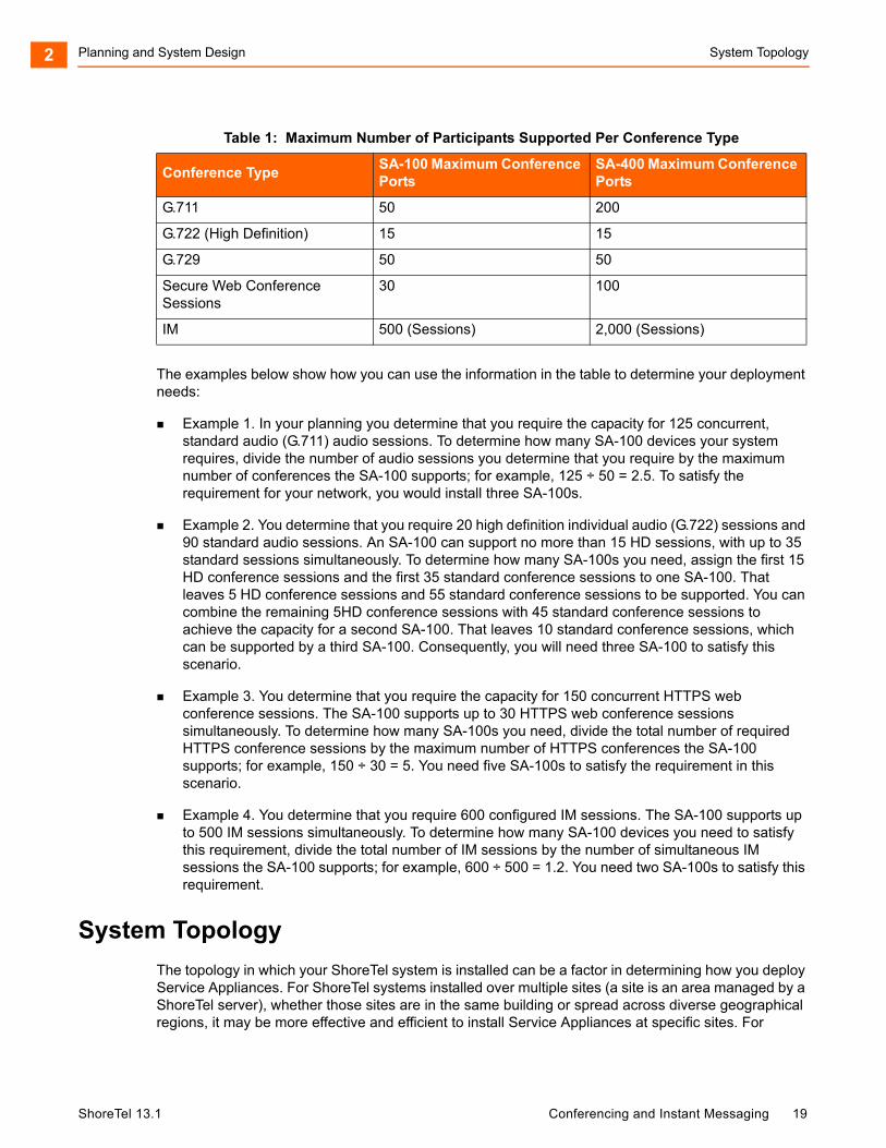
Among the factors to consider in determining how many Service Appliances to deploy are the capabilities of the SA-100 and the SA-400. Table 1 provides information about the maximum number of participants Service Appliances can support by conference type. For additional information, see the Chapter 3, Network Requirements and Preparation.
ShoreTel 13.1 Conferencing and Instant Messaging 18
Planning and System Design System Topology2
The examples below show how you can use the information in the table to determine your deployment needs:
Example 1. In your planning you determine that you require the capacity for 125 concurrent, standard audio (G.711) audio sessions. To determine how many SA-100 devices your system requires, divide the number of audio sessions you determine that you require by the maximum number of conferences the SA-100 supports; for example, 125 ÷ 50 = 2.5. To satisfy the requirement for your network, you would install three SA-100s.
Example 2. You determine that you require 20 high definition individual audio (G.722) sessions and 90 standard audio sessions. An SA-100 can support no more than 15 HD sessions, with up to 35 standard sessions simultaneously. To determine how many SA-100s you need, assign the first 15 HD conference sessions and the first 35 standard conference sessions to one SA-100. That leaves 5 HD conference sessions and 55 standard conference sessions to be supported. You can combine the remaining 5HD conference sessions with 45 standard conference sessions to achieve the capacity for a second SA-100. That leaves 10 standard conference sessions, which can be supported by a third SA-100. Consequently, you will need three SA-100 to satisfy this scenario.
Example 3. You determine that you require the capacity for 150 concurrent HTTPS web conference sessions. The SA-100 supports up to 30 HTTPS web conference sessions simultaneously. To determine how many SA-100s you need, divide the total number of required HTTPS conference sessions by the maximum number of HTTPS conferences the SA-100 supports; for example, 150 ÷ 30 = 5. You need five SA-100s to satisfy the requirement in this scenario.
Example 4. You determine that you require 600 configured IM sessions. The SA-100 supports up to 500 IM sessions simultaneously. To determine how many SA-100 devices you need to satisfy this requirement, divide the total number of IM sessions by the number of simultaneous IM sessions the SA-100 supports; for example, 600 ÷ 500 = 1.2. You need two SA-100s to satisfy this requirement.
System Topology
The topology in which your ShoreTel system is installed can be a factor in determining how you deploy Service Appliances. For ShoreTel systems installed over multiple sites (a site is an area managed by a ShoreTel server), whether those sites are in the same building or spread across diverse geographical regions, it may be more effective and efficient to install Service Appliances at specific sites. For
Table 1: Maximum Number of Participants Supported Per Conference Type
Conference TypeSA-100 Maximum Conference Ports
SA-400 Maximum Conference Ports
G.711 50 200
G.722 (High Definition) 15 15
G.729 50 50
Secure Web Conference Sessions
30 100
IM 500 (Sessions) 2,000 (Sessions)
ShoreTel 13.1 Conferencing and Instant Messaging 19
Planning and System Design Load Balancing2
example, if your experience includes inconsistent WAN connections, limited WAN bandwidth or known WAN quality issues, installing Service Appliances at regional sites and implementing load balancing can minimize the effect the WAN has on conference calls.
Similarly, if your ShoreTel system is servicing users in different cities or countries and many of the conferences are held at local sites, you can save on long distance charges by installing Service Appliances at the local sites to handle local conferences. Other advantages of installing Service Appliances at local sites include:
Savings on inter-site bandwidth
Better quality audio and web sessions
For more information about setting up a remote service appliance, see Setting Up a Service Appliance to Remote Service Appliances on page 55
Load Balancing
ShoreTel Conferencing supports load balancing. The ShoreTel system manages all calls in the system including conference calls from a single source. That means that when a conference is initiated, ShoreTel Conferencing can assess conference resources and shift the conference to an available Service Appliance if the local unit does not have sufficient resources.
Redundancy
The ShoreTel Service Appliance supports failover in cases where a unit loses connectivity or fails. In the event of a loss of network connectivity or unit failure, the ShoreTel system will redirect new conference calls to another Service Appliance unit if resources are available.
Licensing Requirements
Audio conferencing and web conferencing services are enabled through keyed licenses for Audio Conference ports and web conference ports. Licenses enable concurrent access to the services, rather than per user or per appliance. Instant Messaging is enabled in all communicator access levels.
For example, you have a single SA-100 which supports 50 G711 audio conference streams and 30 secure web sessions. To run a concurrent audio/secure web conference for 30 participants would require 30 Audio Conference and 30 web conference licenses.
In order to be a conference host on the system, you must be added as a user, which requires at least a mailbox license.
Note
ShoreTel recommends that you do not install Service Appliances in a network where latency exceeds 100 ms. To operate Service Appliances optimally, network latency and jitter must be minimized. ShoreTel also recommends that the ping lag time between Service Appliances and the ShoreTel headquarters server does not exceed 200 ms. This lag time affects how quickly web pages refresh.
ShoreTel 13.1 Conferencing and Instant Messaging 20

Planning and System Design Licensing Requirements2
ShoreTel 13.1 Conferencing and Instant Messaging 21
CHAPTER
3. Network Requirements andPreparation
Use the information in this chapter to determine specific network requirements for the ShoreTel Service Appliance 100. After determining the network requirements, you will be ready to configure your network appropriately. The topics discussed in this chapter include:
Network Requirements.............................................................................................. 23
Network Bandwidth Requirements for Web Conference Sessions ........................... 24
IP Addressing............................................................................................................ 25
Time Services............................................................................................................ 25
Network Security ....................................................................................................... 25
Deployment Scenarios .............................................................................................. 26
ShoreTel 13.1 Conferencing and Instant Messaging 22
Network Requirements and Preparation Network Requirements3
Network Requirements
ShoreTel Conferencing services require that the underlying network meet all ShoreTel recommendations. Refer to the ShoreTel 13: Planning and Installation Guide for more information for recommendations about deploying a ShoreTel telephony system on your network. Consider the following items when planning your system for audio and web conferences:
Audio conference streams
Delivers adequate bandwidth for toll-quality calls.
Meets the latency and jitter requirements for toll-quality calls.
Meets the packet loss requirements for toll-quality voice.
Bandwidth management to prioritize your voice traffic over your data traffic.
Proper configuration of the ShoreTel Admission Control feature for each site.
Web conference streams
Delivers adequate bandwidth for the typical application you expect users to share.
Maintains a ping lag of not more that 100 ms between Service Appliances and the ShoreTel Headquarters server.
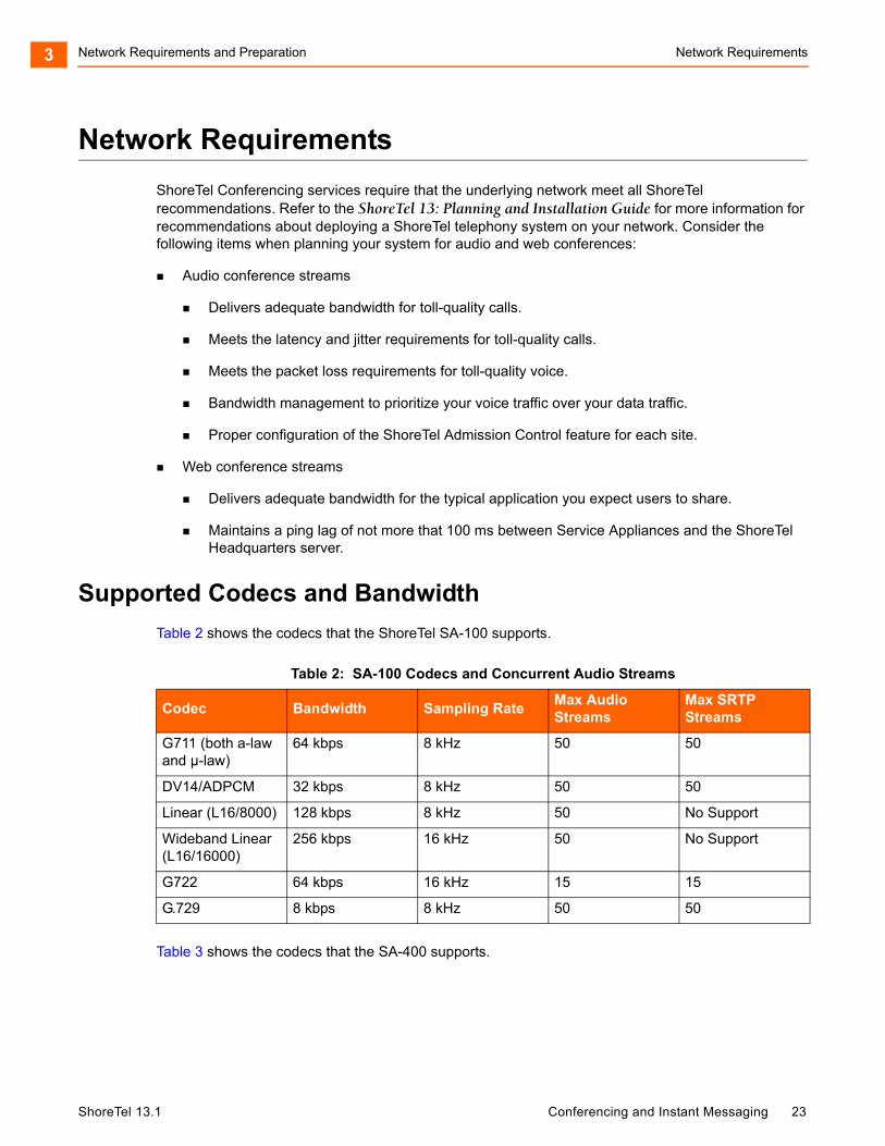
Supported Codecs and Bandwidth
Table 2 shows the codecs that the ShoreTel SA-100 supports.
Table 3 shows the codecs that the SA-400 supports.
Table 2: SA-100 Codecs and Concurrent Audio Streams
Codec Bandwidth Sampling Rate Max Audio Streams
Max SRTP Streams
G711 (both a-law and µ-law)
64 kbps 8 kHz 50 50
DV14/ADPCM 32 kbps 8 kHz 50 50
Linear (L16/8000) 128 kbps 8 kHz 50 No Support
Wideband Linear (L16/16000)
256 kbps 16 kHz 50 No Support
G722 64 kbps 16 kHz 15 15
G.729 8 kbps 8 kHz 50 50
ShoreTel 13.1 Conferencing and Instant Messaging 23
Network Requirements and Preparation Network Bandwidth Requirements for Web Conference Sessions3
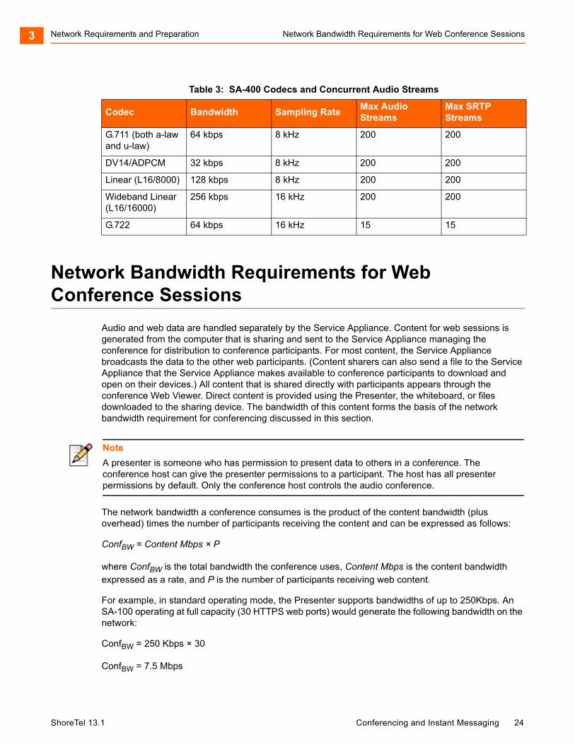
Network Bandwidth Requirements for Web Conference Sessions
Audio and web data are handled separately by the Service Appliance. Content for web sessions is generated from the computer that is sharing and sent to the Service Appliance managing the conference for distribution to conference participants. For most content, the Service Appliance broadcasts the data to the other web participants. (Content sharers can also send a file to the Service Appliance that the Service Appliance makes available to conference participants to download and open on their devices.) All content that is shared directly with participants appears through the conference Web Viewer. Direct content is provided using the Presenter, the whiteboard, or files downloaded to the sharing device. The bandwidth of this content forms the basis of the network bandwidth requirement for conferencing discussed in this section.
The network bandwidth a conference consumes is the product of the content bandwidth (plus overhead) times the number of participants receiving the content and can be expressed as follows:
ConfBW = Content Mbps × P
where ConfBW is the total bandwidth the conference uses, Content Mbps is the content bandwidth expressed as a rate, and P is the number of participants receiving web content.
For example, in standard operating mode, the Presenter supports bandwidths of up to 250Kbps. An SA-100 operating at full capacity (30 HTTPS web ports) would generate the following bandwidth on the network:
ConfBW = 250 Kbps × 30
ConfBW = 7.5 Mbps
Table 3: SA-400 Codecs and Concurrent Audio Streams
Codec Bandwidth Sampling RateMax Audio Streams
Max SRTP Streams
G.711 (both a-law and u-law)
64 kbps 8 kHz 200 200
DV14/ADPCM 32 kbps 8 kHz 200 200
Linear (L16/8000) 128 kbps 8 kHz 200 200
Wideband Linear (L16/16000)
256 kbps 16 kHz 200 200
G.722 64 kbps 16 kHz 15 15
Note
A presenter is someone who has permission to present data to others in a conference. The conference host can give the presenter permissions to a participant. The host has all presenter permissions by default. Only the conference host controls the audio conference.
ShoreTel 13.1 Conferencing and Instant Messaging 24
Network Requirements and Preparation IP Addressing3
IP Addressing
The Service Appliance requires an IP address with a permanent lease or a static IP address. Either of the following methods may be used to assign network parameters:
DHCP from a network server (default out-of-the-box option)
A static IP configured through the maintenance port on the back of the Service Appliance.
The Service Appliance also requires a fully qualified domain name (FQDN) during configuration in ShoreTel Director. When configuring the service appliance, you must plan to use the following FQDNs:
You must have an FQDN for each deployed service appliance.
You must configure you internal and external DNS server to point to the service appliance.
The FQDNs must map correctly, both internally and externally, to the IP address of the service appliances.
See "Installing Service Appliances" section on page 38 for more information about configuring the IP address.
Time Services
The Service Appliance requires a connection to time services in order to support ShoreTel Conferencing services.
The address of the NTP server can be provided to the Service Appliance through DHCP option 004 (if DHCP is used) or configured statically.
See the ShoreTel Planning and Installation Guide for detailed instructions on selecting an NTP public server if you do not run an NTP server within your organization.
Network Security
This section discusses network security concerns that can come up when you deploy Service Appliances.
Internal Firewall
Service Appliances can be deployed in the DMZ, allowing external participants to access web conferences. Positioning in the DMZ places the Service Appliance in a privileged security position within the customer's network infrastructure. Therefore, the Service Appliance features an embedded, customer-administered firewall to control access between unsecure external environments and internal networks. Proactive security policies and strict management of evolving internet security risks are essential to maintain network security.
ShoreTel 13.1 Conferencing and Instant Messaging 25
Network Requirements and Preparation Security Considerations3
Security Considerations
As security threats evolve new vulnerabilities may be discovered that require immediate resolution. ShoreTel provides upgrades to the appliance software and updates for critical security patches. If required, these upgrades are distributed independently from the standard release cycle for software upgrades.
Should critical security patches be required to the appliance operation or file systems, a mini-installer is used to implement immediate fixes to the platform images. This allows customer IT departments to quickly protect their networks without having to complete an entire release upgrade.
Hotfixes and patches for the appliance are incorporated into the next build or release.
Procedures to apply security patches to the appliance operating system and applications are described in the ShoreTel Maintenance Guide and are also distributed via e-mail or other customer notification pathways such as the ShoreTel support website.
Deployment Scenarios
The ShoreTel Service Appliance 100 may be deployed both internal to the LAN or externally in a company DMZ.
Deployment scenarios may include multiple installations of appliances in a ShoreTel system.
However, in any multi-appliance deployment scenario, if one appliance is accessible for external access then all appliances must be accessible for external access.
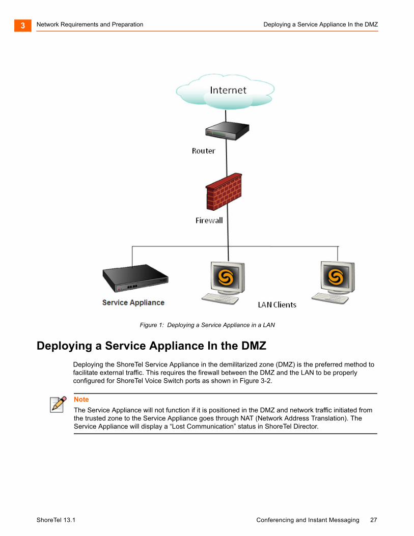
Deploying a Service Appliance in the LAN
In the scenario where a Service Appliance is deployed on the trusted internal network, the following requirements apply:
The network requires port-forwarding through the firewall which is restricted to web ports (80-unsecure & 443-HTTPS). Alternatively, a reverse-proxy server can be used instead of port-forwarding but this requires the provision of an additional server.
The network requires DNS configuration both internally to resolve internal addresses and externally to resolve to external addresses.
Alternatively, a network can be configured with DNS configured for external addressing only and a host file configurated to handle traffic internally.
The following figure shows deploying a service appliance in the LAN.
ShoreTel 13.1 Conferencing and Instant Messaging 26
Network Requirements and Preparation Deploying a Service Appliance In the DMZ3
Figure 1: Deploying a Service Appliance in a LAN
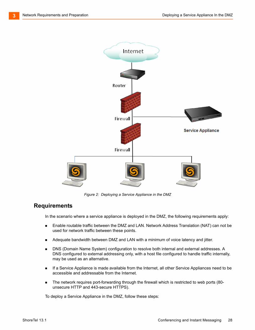
Deploying a Service Appliance In the DMZ
Deploying the ShoreTel Service Appliance in the demilitarized zone (DMZ) is the preferred method to facilitate external traffic. This requires the firewall between the DMZ and the LAN to be properly configured for ShoreTel Voice Switch ports as shown in Figure 3-2.
Note
The Service Appliance will not function if it is positioned in the DMZ and network traffic initiated from the trusted zone to the Service Appliance goes through NAT (Network Address Translation). The Service Appliance will display a “Lost Communication” status in ShoreTel Director.
ShoreTel 13.1 Conferencing and Instant Messaging 27
Network Requirements and Preparation Deploying a Service Appliance In the DMZ3
Figure 2: Deploying a Service Appliance in the DMZ
Requirements
In the scenario where a service appliance is deployed in the DMZ, the following requirements apply:
Enable routable traffic between the DMZ and LAN. Network Address Translation (NAT) can not be used for network traffic between these points.
Adequate bandwidth between DMZ and LAN with a minimum of voice latency and jitter.
DNS (Domain Name System) configuration to resolve both internal and external addresses. A DNS configured to external addressing only, with a host file configured to handle traffic internally, may be used as an alternative.
If a Service Appliance is made available from the Internet, all other Service Appliances need to be accessible and addressable from the Internet.
The network requires port-forwarding through the firewall which is restricted to web ports (80-unsecure HTTP and 443-secure HTTPS).
To deploy a Service Appliance in the DMZ, follow these steps:
ShoreTel 13.1 Conferencing and Instant Messaging 28
Network Requirements and Preparation Deploying a Service Appliance In the DMZ3
1. Configure your firewall to allow traffic from the IP address assigned to the Service Appliance to go through.
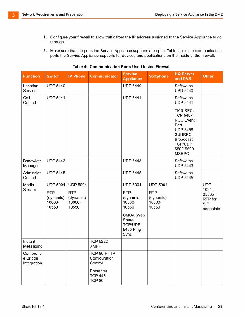
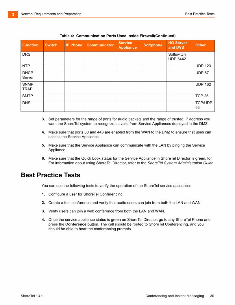
2. Make sure that the ports the Service Appliance supports are open. Table 4 lists the communication ports the Service Appliance supports for devices and applications on the inside of the firewall.
Table 4: Communication Ports Used Inside Firewall
Function Switch IP Phone CommunicatorService Appliance
SoftphoneHQ Serverand DVS
Other
Location Service
UDP 5440 UDP 5440 SoftswitchUPD 5440
Call Control
UDP 5441 UDP 5441 SoftswitchUDP 5441
TMS RPC:TCP 5457 NCC Event PortUDP 5458 SUNRPC BroadcastTCP/UDP 5500-5600 MSRPC
Bandwidth Manager
UDP 5443 UDP 5443 SoftswitchUDP 5443
Admission Control
UDP 5445 UDP 5445 SoftswitchUDP 5445
Media Stream
UDP 5004
RTP (dynamic) 10000-10550
UDP 5004
RTP (dynamic) 10000-10550
UDP 5004
RTP (dynamic) 10000-10550
CMCA (Web ShareTCP/UDP 5450 Ping Sync
UDP 5004
RTP (dynamic) 10000-10550
UDP 1024-65535 RTP for SIP endpoints
Instant Messaging
TCP 5222-XMPP
Conference Bridge Integration
TCP 80-HTTP Configuration Control
PresenterTCP 443TCP 80
ShoreTel 13.1 Conferencing and Instant Messaging 29
Network Requirements and Preparation Best Practice Tests3
3. Set parameters for the range of ports for audio packets and the range of trusted IP address you want the ShoreTel system to recognize as valid from Service Appliances deployed in the DMZ.
4. Make sure that ports 80 and 443 are enabled from the WAN to the DMZ to ensure that uses can access the Service Appliance.
5. Make sure that the Service Appliance can communicate with the LAN by pinging the Service Appliance.
6. Make sure that the Quick Look status for the Service Appliance in ShoreTel Director is green. for For information about using ShoreTel Director, refer to the ShoreTel System Administration Guide.
Best Practice Tests
You can use the following tests to verify the operation of the ShoreTel service appliance:
1. Configure a user for ShoreTel Conferencing.
2. Create a test conference and verify that audio users can join from both the LAN and WAN.
3. Verify users can join a web conference from both the LAN and WAN.
4. Once the service appliance status is green on ShoreTel Director, go to any ShoreTel Phone and press the Conference button. The call should be routed to ShoreTel Conferencing, and you should be able to hear the conferencing prompts.
DRS SoftswitchUDP 5442
NTP UDP 123
DHCP Server
UDP 67
SNMP TRAP
UDP 162
SMTP TCP 25
DNS TCP/UDP 53
Table 4: Communication Ports Used Inside Firewall(Continued)
Function Switch IP Phone CommunicatorService Appliance
SoftphoneHQ Serverand DVS
Other
ShoreTel 13.1 Conferencing and Instant Messaging 30
CHAPTER
4. Site Requirements andPreparation
This chapter provides information about preparing your site for Service Appliance installation, including concerns such as physical space, environment, and cabling. This chapter includes the following topics:
Recommendations .................................................................................................... 32
Specifications ............................................................................................................ 32
SA-100 Specifications......................................................................................... 33
SA-400 Specifications......................................................................................... 36
Environmental Requirements.................................................................................... 37
ShoreTel 13.1 Conferencing and Instant Messaging 31
Site Requirements and Preparation Recommendations4
Recommendations
The following recommendations will assist you in planning and preparing your site for the ShoreTel system.
Hire a cabling contractor to install your racks, patch panels, and cabling.
Have two RJ-48C cables ready for each Service Appliance.
Use surge protector or UPS.
For remote deployment, your network should have 384 kbps bandwidth or better available between the FTP server and the remote Service Appliance for downloading upgrade software.
Specifications
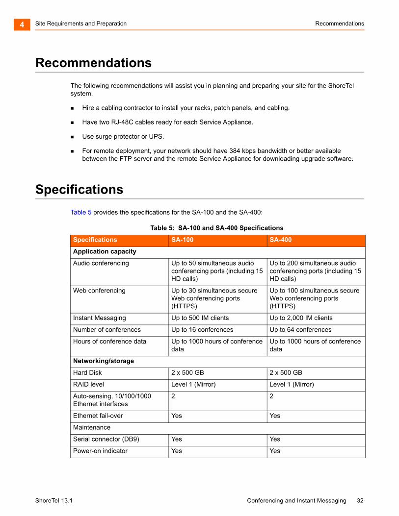
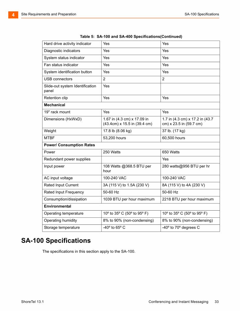
Table 5 provides the specifications for the SA-100 and the SA-400:
Table 5: SA-100 and SA-400 Specifications
Specifications SA-100 SA-400
Application capacity
Audio conferencing Up to 50 simultaneous audio conferencing ports (including 15 HD calls)
Up to 200 simultaneous audio conferencing ports (including 15 HD calls)
Web conferencing Up to 30 simultaneous secure Web conferencing ports (HTTPS)
Up to 100 simultaneous secure Web conferencing ports (HTTPS)
Instant Messaging Up to 500 IM clients Up to 2,000 IM clients
Number of conferences Up to 16 conferences Up to 64 conferences
Hours of conference data Up to 1000 hours of conference data
Up to 1000 hours of conference data
Networking/storage
Hard Disk 2 x 500 GB 2 x 500 GB
RAID level Level 1 (Mirror) Level 1 (Mirror)
Auto-sensing, 10/100/1000 Ethernet interfaces
2 2
Ethernet fail-over Yes Yes
Maintenance
Serial connector (DB9) Yes Yes
Power-on indicator Yes Yes
ShoreTel 13.1 Conferencing and Instant Messaging 32
Site Requirements and Preparation SA-100 Specifications4
SA-100 Specifications
The specifications in this section apply to the SA-100.
Hard drive activity indicator Yes Yes
Diagnostic indicators Yes Yes
System status indicator Yes Yes
Fan status indicator Yes Yes
System identification button Yes Yes
USB connectors 2 2
Slide-out system Identification panel
Yes
Retention clip Yes Yes
Mechanical
19" rack mount Yes Yes
Dimensions (HxWxD) 1.67 in (4.3 cm) x 17.09 in (43.4cm) x 15.5 in (39.4 cm)
1.7 in (4.3 cm) x 17.2 in (43.7 cm) x 23.5 in (59.7 cm)
Weight 17.8 lb (8.06 kg) 37 lb. (17 kg)
MTBF 53,200 hours 60,500 hours
Power/ Consumption Rates
Power 250 Watts 650 Watts
Redundant power supplies Yes
Input power 108 Watts @368.5 BTU per hour
280 watts@956 BTU per hr
AC input voltage 100-240 VAC 100-240 VAC
Rated Input Current 3A (115 V) to 1.5A (230 V) 8A (115 V) to 4A (230 V)
Rated Input Frequency 50-60 Hz 50-60 Hz
Consumption/dissipation 1039 BTU per hour maximum 2218 BTU per hour maximum
Environmental
Operating temperature 10º to 35º C (50º to 95º F) 10º to 35º C (50º to 95º F)
Operating humidity 8% to 90% (non-condensing) 8% to 90% (non-condensing)
Storage temperature -40º to 65º C -40º to 70º degrees C
Table 5: SA-100 and SA-400 Specifications(Continued)
ShoreTel 13.1 Conferencing and Instant Messaging 33
Site Requirements and Preparation SA-100 Specifications4
Front Panel
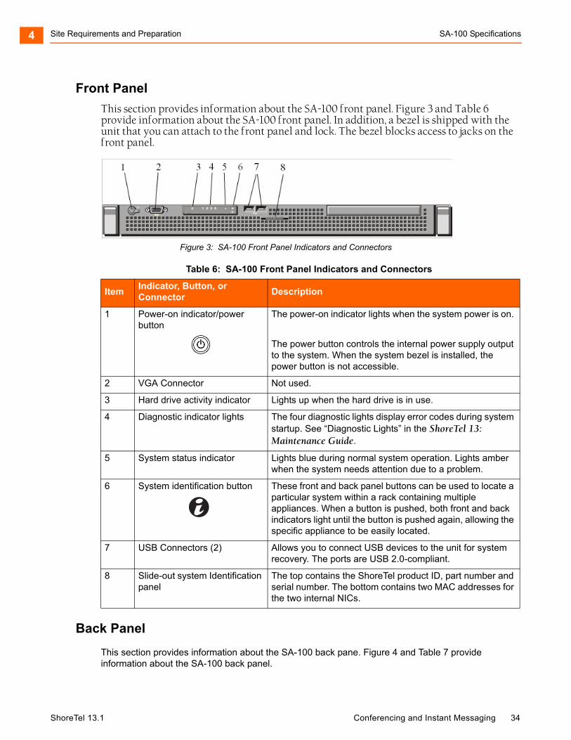
This section provides information about the SA-100 front panel. Figure 3 and Table 6 provide information about the SA-100 front panel. In addition, a bezel is shipped with the unit that you can attach to the front panel and lock. The bezel blocks access to jacks on the front panel.
Figure 3: SA-100 Front Panel Indicators and Connectors
Back Panel
This section provides information about the SA-100 back pane. Figure 4 and Table 7 provide information about the SA-100 back panel.
Table 6: SA-100 Front Panel Indicators and Connectors
ItemIndicator, Button, or Connector
Description
1 Power-on indicator/power button
The power-on indicator lights when the system power is on.
The power button controls the internal power supply output to the system. When the system bezel is installed, the power button is not accessible.
2 VGA Connector Not used.
3 Hard drive activity indicator Lights up when the hard drive is in use.
4 Diagnostic indicator lights The four diagnostic lights display error codes during system startup. See “Diagnostic Lights” in the ShoreTel 13: Maintenance Guide.
5 System status indicator Lights blue during normal system operation. Lights amber when the system needs attention due to a problem.
6 System identification button These front and back panel buttons can be used to locate a particular system within a rack containing multiple appliances. When a button is pushed, both front and back indicators light until the button is pushed again, allowing the specific appliance to be easily located.
7 USB Connectors (2) Allows you to connect USB devices to the unit for system recovery. The ports are USB 2.0-compliant.
8 Slide-out system Identification panel
The top contains the ShoreTel product ID, part number and serial number. The bottom contains two MAC addresses for the two internal NICs.
ShoreTel 13.1 Conferencing and Instant Messaging 34
Site Requirements and Preparation SA-100 Specifications4
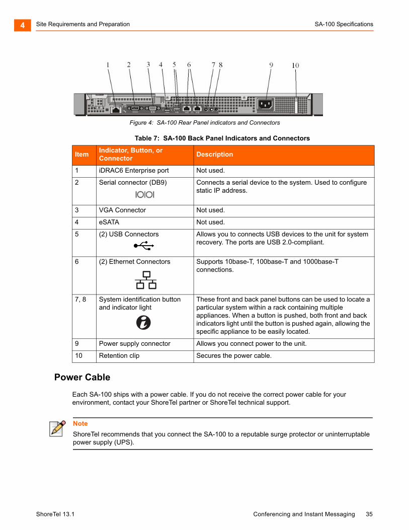
Figure 4: SA-100 Rear Panel indicators and Connectors
Power Cable
Each SA-100 ships with a power cable. If you do not receive the correct power cable for your environment, contact your ShoreTel partner or ShoreTel technical support.
Table 7: SA-100 Back Panel Indicators and Connectors
ItemIndicator, Button, or Connector
Description
1 iDRAC6 Enterprise port Not used.
2 Serial connector (DB9) Connects a serial device to the system. Used to configure static IP address.
3 VGA Connector Not used.
4 eSATA Not used.
5 (2) USB Connectors Allows you to connects USB devices to the unit for system recovery. The ports are USB 2.0-compliant.
6 (2) Ethernet Connectors Supports 10base-T, 100base-T and 1000base-T connections.
7, 8 System identification button and indicator light
These front and back panel buttons can be used to locate a particular system within a rack containing multiple appliances. When a button is pushed, both front and back indicators light until the button is pushed again, allowing the specific appliance to be easily located.
9 Power supply connector Allows you connect power to the unit.
10 Retention clip Secures the power cable.
Note
ShoreTel recommends that you connect the SA-100 to a reputable surge protector or uninterruptable power supply (UPS).
ShoreTel 13.1 Conferencing and Instant Messaging 35
Site Requirements and Preparation SA-400 Specifications4
Ethernet Ports
The SA-100 uses an auto-sensing, 10/100/1000 Ethernet interface. Two RJ-48C Ethernet connections (GB1 and GB2) are provided to provide fault-tolerant deployment. The ports use the same MAC Ethernet address and IP address but are independent of each other and can be used in any sequence. However, when both ports are connected, only one will be active at a time. Should the active interface lose the link, the other interface is made active. You must use Category 5 or higher cabling.
The SA-100 provides two methods of fault tolerance. To protect against Ethernet switch failure, connect Ethernet ports GB1 and GB2 to separate Ethernet switches. To protect against port or cable failure, connect LAN1 and LAN2 to separate ports on the same Ethernet switch.
Maintenance Cable
The ShoreTel SA-100 provides a maintenance port that you can connect a terminal to using a DB-9, female-to-female, null-modem connector. You can use the maintenance port to assign the unit IP address parameters when DHCP is not used.
SA-400 Specifications
The specifications in this section apply to the SA-400.
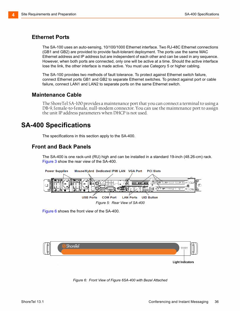
Front and Back Panels
The SA-400 is one rack-unit (RU) high and can be installed in a standard 19-inch (48.26-cm) rack. Figure 3 show the rear view of the SA-400.
Figure 5: Rear View of SA-400
Figure 6 shows the front view of the SA-400.
Figure 6: Front View of Figure 6SA-400 with Bezel Attached
Light Indicators
ShoreTel 13.1 Conferencing and Instant Messaging 36
Site Requirements and Preparation Environmental Requirements4
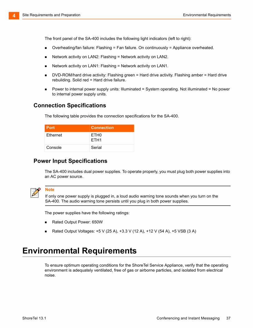
The front panel of the SA-400 includes the following light indicators (left to right):
Overheating/fan failure: Flashing = Fan failure. On continuously = Appliance overheated.
Network activity on LAN2: Flashing = Network activity on LAN2.
Network activity on LAN1: Flashing = Network activity on LAN1.
DVD-ROM/hard drive activity: Flashing green = Hard drive activity. Flashing amber = Hard drive rebuilding. Solid red = Hard drive failure.
Power to internal power supply units: Illuminated = System operating. Not illuminated = No power to internal power supply units.
Connection Specifications
The following table provides the connection specifications for the SA-400.
Power Input Specifications
The SA-400 includes dual power supplies. To operate properly, you must plug both power supplies into an AC power source.
The power supplies have the following ratings:
Rated Output Power: 650W
Rated Output Voltages: +5 V (25 A), +3.3 V (12 A), +12 V (54 A), +5 VSB (3 A)
Environmental Requirements
To ensure optimum operating conditions for the ShoreTel Service Appliance, verify that the operating environment is adequately ventilated, free of gas or airborne particles, and isolated from electrical noise.
Port Connection
Ethernet ETH0ETH1
Console Serial
Note
If only one power supply is plugged in, a loud audio warning tone sounds when you turn on the SA-400. The audio warning tone persists until you plug in both power supplies.
ShoreTel 13.1 Conferencing and Instant Messaging 37
CHAPTER
5. Installing Service Appliances
This chapter provides information about mounting Service Appliances in a rack, assigning the units an IP Address, and connecting it to the network. The topics discussed in this chapter include:
Preparing for Installation ........................................................................................... 39
Verifying the Contents of the Box.............................................................................. 39
Location Guidelines................................................................................................... 40
Installation ................................................................................................................. 40
Setting the IP Address Manually ............................................................................... 42
Using DHCP to Set the IP Address........................................................................... 44
Installing the Bezel .................................................................................................... 45
Configuring the Unit for Operation ............................................................................ 46
Note
Unless otherwise specified, the instructions in this chapter apply to both the SA-100 and the SA-400.
ShoreTel 13.1 Conferencing and Instant Messaging 38
Installing Service Appliances Preparing for Installation5
Preparing for Installation
The section lists things that are recommended and required to install a ShoreTel Service Appliance.
Computer mounting rack capable of supporting 1U equipment.
Adequate clearance in the front and back of the rack to allow adequate ventilation.
Surge protector or UPS.
IP address to assign to Service Appliance.
ShoreTel recommends that you assign a static IP address to all Service Appliances.
IP address of the gateway that you want the Service Appliances to use.
Subnet address that you want the Service Appliances to use.
Computer with a terminal emulation program installed.
DB-9 serial cable.
The IP network between the main and remote sites meets the bandwidth, latency, jitter, and packet loss requirements for a multisite installation.
The IP network between the main and remote site has quality of service in place such that voice is prioritized ahead of data.
You have appropriate firewall provisions in place, including VPN if applicable.
All power and environmental requirements are met.
Verifying the Contents of the Box
This section lists the items you should receive in your ShoreTel Service Appliance package. Inspect the package carefully before you open it and contact the shipper if it is damaged. If items are missing from the package, contact your ShoreTel partner or ShoreTel technical support. The items in the box include the following:
ShoreTel Service Appliance
Either one power cord for the SA-100 or two power cords for the SA-400
Rack mounting kit
ShoreTel front bezel kit
ShoreTel Quick Install Guide.
Product Information Guide
ShoreTel 13.1 Conferencing and Instant Messaging 39
Installing Service Appliances Location Guidelines5
Location Guidelines
Except when they are specified separately, these guidelines apply to both the SA-100 and the SA-400:
Operating temperature: 10° to 35° C (50° to 95° F)
Operating humidity: 8% to 90% noncondensing
Adequate ventilation after the Service Appliances are installed
Installation
Follow the procedures in this section to install the Service Appliance.
Mounting the ShoreTel Service Appliance
The Service Appliance is shipped with a rack mounting kit that includes mounting instructions. The kit is designed to accommodate different types of equipment racks. Use the kit instructions to attach the rails to the Service Appliance and mount the unit in the rack.
Connecting the AC Power to the SA-100
Service Appliances are shipped with a power cable that are appropriate for the location to which they are shipped. If you receive the wrong cable with the unit, contact your ShoreTel partner or ShoreTel technical support.
Press the power button on the front panel (see SA-100 Specifications on page 33) to turn the unit on. The LED in the power button comes on and the SA-100 performs its start-up process. The fan spins up and a sequence of numbers flash on the LED block on the front panel. The fan will quiet down and a solid LED appear when the process is complete. The process takes about 30 seconds. If the fan does not come on or the numbers do not flash, ensure that the power cord is plugged into the power source and the power source is working. If the appliance still fails to power on, contact your ShoreTel partner or ShoreTel technical support.
WARNING!
Make sure there is ample space between the front panel and back panel of the Service Appliance and any other surface to allow ample ventilation for the unit.
WARNING!
Electrical surges in the AC line can damage unprotected equipment. ShoreTel recommends that you use an AC surge protector or a UPS to connect a Service Appliance to the AC line.
ShoreTel 13.1 Conferencing and Instant Messaging 40
Installing Service Appliances Connecting AC Power to the SA-4005
Connecting AC Power to the SA-400
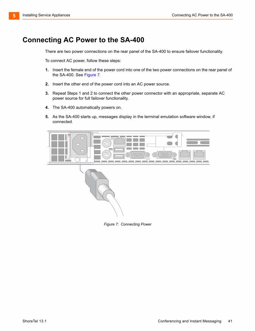
There are two power connections on the rear panel of the SA-400 to ensure failover functionality.
To connect AC power, follow these steps:
1. Insert the female end of the power cord into one of the two power connections on the rear panel of the SA-400. See Figure 7.
2. Insert the other end of the power cord into an AC power source.
3. Repeat Steps 1 and 2 to connect the other power connector with an appropriate, separate AC power source for full failover functionality.
4. The SA-400 automatically powers on.
5. As the SA-400 starts up, messages display in the terminal emulation software window, if connected.
Figure 7: Connecting Power
ShoreTel 13.1 Conferencing and Instant Messaging 41
Installing Service Appliances Setting the IP Address Manually5
Setting the IP Address Manually
This section describes how to set the IP address on the Service Appliance manually. ShoreTel recommends that you use a static IP address for Service Appliance. You can also use DHCP to assign the unit an IP address. If you choose to use DHCP, you must configure the DHCP server with address information for the Service Appliance prior to turning on the unit. You can use the instruction provided in this section to obtain the Ethernet address of the unit.
To configure the IP address manually, you need the following:
Valid IP address for the segment in which you want to install the Service Appliance.
Computer with terminal emulation software installed.
Null modem DB-9 serial cable.
1. Connect the DB-9 serial cable to the serial port on the back panel of the Service Appliance and a computer.
2. Power on the Service Appliance and the computer.
3. On the computer, start a terminal emulation program and set the following parameters:
Baud rate: 19200 bps
Data Bits: 8
Parity: None
Stop Bit: 1
Flow control: None
4. At the Login prompt, type the user ID required to enter the CLI interface and press Enter. The default login name is root. The Password prompt appears.
5. At the Password prompt, type the password required to enter the CLI interface and press Enter. The default password is ShoreTel.
Note
The Service Appliance is shipped from the factory configured to use DHCP to set IP address. That means that unless otherwise set, the first time the unit is turned on with an Ethernet cable connecting it to the network the unit will seek an IP address from the DHCP server on the network.
Note
The Service Appliance performs a start-up process when it is turned on. A sequence of numbers flash on the LED panel during start up, and a solid LED appears when the process is complete. The process takes about 30 seconds.
ShoreTel 13.1 Conferencing and Instant Messaging 42
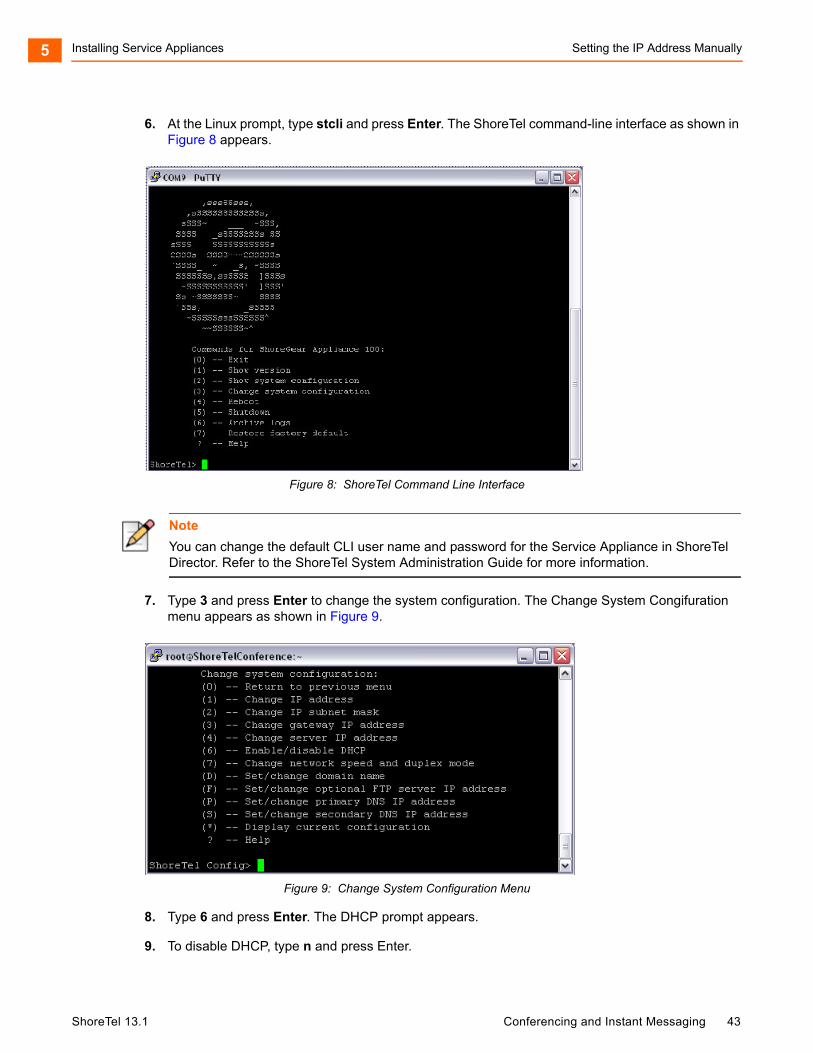
Installing Service Appliances Setting the IP Address Manually5
6. At the Linux prompt, type stcli and press Enter. The ShoreTel command-line interface as shown in Figure 8 appears.
Figure 8: ShoreTel Command Line Interface
7. Type 3 and press Enter to change the system configuration. The Change System Congifuration menu appears as shown in Figure 9.
Figure 9: Change System Configuration Menu
8. Type 6 and press Enter. The DHCP prompt appears.
9. To disable DHCP, type n and press Enter.
Note
You can change the default CLI user name and password for the Service Appliance in ShoreTel Director. Refer to the ShoreTel System Administration Guide for more information.
ShoreTel 13.1 Conferencing and Instant Messaging 43
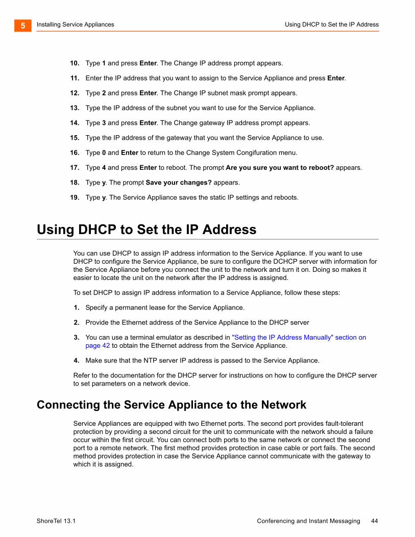
Installing Service Appliances Using DHCP to Set the IP Address5
10. Type 1 and press Enter. The Change IP address prompt appears.
11. Enter the IP address that you want to assign to the Service Appliance and press Enter.
12. Type 2 and press Enter. The Change IP subnet mask prompt appears.
13. Type the IP address of the subnet you want to use for the Service Appliance.
14. Type 3 and press Enter. The Change gateway IP address prompt appears.
15. Type the IP address of the gateway that you want the Service Appliance to use.
16. Type 0 and Enter to return to the Change System Congifuration menu.
17. Type 4 and press Enter to reboot. The prompt Are you sure you want to reboot? appears.
18. Type y. The prompt Save your changes? appears.
19. Type y. The Service Appliance saves the static IP settings and reboots.
Using DHCP to Set the IP Address
You can use DHCP to assign IP address information to the Service Appliance. If you want to use DHCP to configure the Service Appliance, be sure to configure the DCHCP server with information for the Service Appliance before you connect the unit to the network and turn it on. Doing so makes it easier to locate the unit on the network after the IP address is assigned.
To set DHCP to assign IP address information to a Service Appliance, follow these steps:
1. Specify a permanent lease for the Service Appliance.
2. Provide the Ethernet address of the Service Appliance to the DHCP server
3. You can use a terminal emulator as described in "Setting the IP Address Manually" section on page 42 to obtain the Ethernet address from the Service Appliance.
4. Make sure that the NTP server IP address is passed to the Service Appliance.
Refer to the documentation for the DHCP server for instructions on how to configure the DHCP server to set parameters on a network device.
Connecting the Service Appliance to the Network
Service Appliances are equipped with two Ethernet ports. The second port provides fault-tolerant protection by providing a second circuit for the unit to communicate with the network should a failure occur within the first circuit. You can connect both ports to the same network or connect the second port to a remote network. The first method provides protection in case cable or port fails. The second method provides protection in case the Service Appliance cannot communicate with the gateway to which it is assigned.
ShoreTel 13.1 Conferencing and Instant Messaging 44
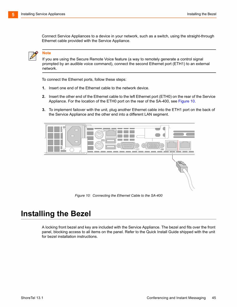
Installing Service Appliances Installing the Bezel5
Connect Service Appliances to a device in your network, such as a switch, using the straight-through Ethernet cable provided with the Service Appliance.
To connect the Ethernet ports, follow these steps:
1. Insert one end of the Ethernet cable to the network device.
2. Insert the other end of the Ethernet cable to the left Ethernet port (ETH0) on the rear of the Service Appliance. For the location of the ETH0 port on the rear of the SA-400, see Figure 10.
3. To implement failover with the unit, plug another Ethernet cable into the ETH1 port on the back of the Service Appliance and the other end into a different LAN segment.
Figure 10: Connecting the Ethernet Cable to the SA-400
Installing the Bezel
A locking front bezel and key are included with the Service Appliance. The bezel and fits over the front panel, blocking access to all items on the panel. Refer to the Quick Install Guide shipped with the unit for bezel installation instructions.
Note
If you are using the Secure Remote Voice feature (a way to remotely generate a control signal prompted by an audible voice command), connect the second Ethernet port (ETH1) to an external network.
ShoreTel 13.1 Conferencing and Instant Messaging 45
Installing Service Appliances Configuring the Unit for Operation5
Configuring the Unit for Operation
After you have mounted the Service Appliance in a rack and connected it to the network, you must configure the ShoreTel system to use the unit. ShoreTel Director is used to configure the ShoreTel system to use the Service Appliance. For information about using ShoreTel Director to add a new Service Appliance, see the "Adding a Service Appliance to the ShoreTel Site" section on page 52.
For information about using ShoreTel Director, refer to the ShoreTel System Administration Guide.
ShoreTel 13.1 Conferencing and Instant Messaging 46
CHAPTER
6. Configuring the ServiceAppliance
You must register the Service Appliance with the ShoreTel system and configure the system to use the appliance.
Topics discussed in this chapter include:
Upgrading the Firmware............................................................................................ 48
Service Appliance Configuration Process ................................................................. 48
Configuring the Network Time Protocol (NTP) Server .............................................. 49
Installing Licenses..................................................................................................... 49
Configuring a Conference Extension ........................................................................ 50
Turning Off Port 5004................................................................................................ 52
Setting up the ShoreTel System................................................................................ 52
Configuring the Conference Viewer Page................................................................. 56
Configuring the Client Interface................................................................................. 58
Configuring HTTPS................................................................................................... 59
Creating Users .......................................................................................................... 63
Configuring Instant Messaging.................................................................................. 63
Connecting with the Microsoft Exchange Server ...................................................... 65
Conference Administration Interface......................................................................... 68
Conferences.............................................................................................................. 69
ShoreTel 13.1 Conferencing and Instant Messaging 47
Configuring the Service Appliance Upgrading the Firmware6
Upgrading the Firmware
During the ShoreTel Director configuration, the appliance may require a firmware upgrade to the latest version.
Upgrading the firmware of a Service Appliance located at a remote site requires a minimum bandwidth of 384 kbps between the appliance and the ShoreTel headquarters server providing the upgrade firmware.
A remote upgrade may not be possible if the minimum required bandwidth is not available.
The firmware upgrade requires 45 minutes at the minimum bandwidth; higher bandwidth reduces the upgrade time.
For more information on ShoreTel Director, see the ShoreTel System Administration Guide.
Service Appliance Configuration Process
Configure Network Time Protocol (NTP) server. (page 49)
This step is required only for static IP or DHCP configurations.
Install Licenses. (page 49)
Configure Conference Extension. (page 50)
Turn off Port 5004. (page 52)
Add the Service Appliance to ShoreTel Site. (page 52)
Verify date and time synchronization. (page 54)
Configure Backup for Service Appliance on the headquarters server. (page 54)
Configure System Mechanism. (page 56)
Configure Conference Web Page. (page 56)
Configure Client Interface. (page 58)
Configure HTTPS. (page 59)
Create Service Appliance users. (page 63)
Configure instant messaging. (page 63)
ShoreTel 13.1 Conferencing and Instant Messaging 48
Configuring the Service Appliance Configuring the Network Time Protocol (NTP) Server6
Configuring the Network Time Protocol (NTP) Server
The NTP server is used to synchronize the clock on the Service Appliance. The NTP server must be configured for every Service Appliance in a site.
1. In Director, click Sites.
2. Under Sites, click the name of the site that includes a Service Appliance.
3. The Edit Site window is opened.
4. Scroll down to Network Time Protocol Server.
5. Enter the IP address of your NTP.
6. Click Save.
7. Exit Director.
8. Reboot the Service Appliance.
The date and time on the Service Appliance are synchronized with the date and time on the NTP server.
Installing Licenses
You must install an audio conference license and a web conference license for each audio and web conference participant you want the ShoreTel system to support.
Each SA-100 can support up to 50 simultaneous audio conferences, 30 simultaneous web conferences, and 500 IM users.
The ShoreTel system can support up to 250 audio conference participants and web conference participants. It can also support 2500 simultaneous active IM users. This section describes how to obtain and install conference licenses.
Obtaining Conference Licenses
1. Contact your ShoreTel partner or reseller and purchase the number and type of licenses you need. The partner or reseller will give you a purchase order number.
2. Launch ShoreTel Director.
3. Click Administrator > System Parameters >Licenses > Keys. The License Keys page appears.
Note
This procedure is required only for static IP addresses or DHCP configurations that do not already have a configured NTP server.
ShoreTel 13.1 Conferencing and Instant Messaging 49
Configuring the Service Appliance Installing the Licenses6
4. Click the Register and Request System Key button at the top of the page. The Contact Information page appears.
5. Enter the information requested in the Register and request system key section. Be sure to include the Sales order number from your purchase and your primary contact information.
6. Click the Now button above the information fields.
Your request is sent to ShoreTel for processing. Your license key will be sent presently.
Installing the Licenses
1. View the license packet that you received from ShoreTel.
2. Launch ShoreTel Director and in the ShoreTel Director menu click Administration > System Parameters > Licenses > Keys. The License Key Info dialog box appears.
3. Click the New button at the top of the page. The Contact Information page appears.
4. In the Key field, enter the license key that you received from ShoreTel.
5. In the Comment field, enter a description of the license.
6. Click Save.
Configuring a Conference Extension
The ShoreTel system automatically creates a system-wide conference number that it assigns an internal ShoreTel extension. This is a number that all ShoreTel users can use to initiate or join a ShoreTel conference. You can change extension manually and even use an external phone number for the conference extension.
Each Service Appliance that you install is also automatically assigned a ShoreTel extension. This number can be used by local users to access the unit to initiate conference calls. You can also change the extension number assigned to the unit.
This section describes how to change the extension and assign an external number.
To change the internal extension and assign an external number, follow this procedure:
1. Launch ShoreTel Director.
2. Click Administration > System Parameters >System Extensions. The Systems Parameters page as shown in Figure 11 appears.
Note
To configure a conference extension, you must have a properly mapped phone number in ShoreTel Director.
ShoreTel 13.1 Conferencing and Instant Messaging 50
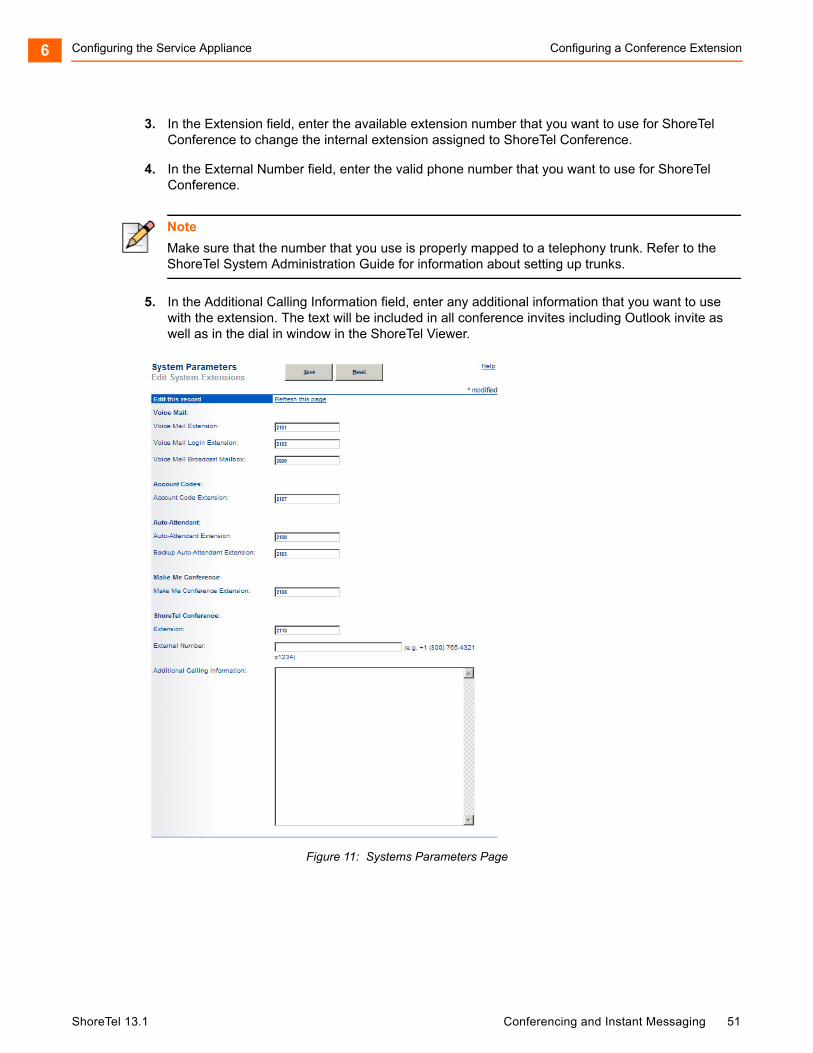
Configuring the Service Appliance Configuring a Conference Extension6
3. In the Extension field, enter the available extension number that you want to use for ShoreTel Conference to change the internal extension assigned to ShoreTel Conference.
4. In the External Number field, enter the valid phone number that you want to use for ShoreTel Conference.
5. In the Additional Calling Information field, enter any additional information that you want to use with the extension. The text will be included in all conference invites including Outlook invite as well as in the dial in window in the ShoreTel Viewer.
Figure 11: Systems Parameters Page
Note
Make sure that the number that you use is properly mapped to a telephony trunk. Refer to the ShoreTel System Administration Guide for information about setting up trunks.
ShoreTel 13.1 Conferencing and Instant Messaging 51
Configuring the Service Appliance Turning Off Port 50046
Turning Off Port 5004
The Service Appliance does not support using port 5004 for RTP audio transmissions. Make sure that the option to use port 5004 for RTP is turned off:
1. Launch ShoreTel Director.
2. Click Administration > Call Control > Options. The Call Control Options page appears.
3. Uncheck the Always Use Port 5004 for RTP check box.
4. Click Save.
5. Reboot all ShoreTel equipment, in the following order: Headquarters DVSes, Conference Bridges, ShoreGear switches, and all IP phones.
Setting up the ShoreTel System
This section describes how to set up the ShoreTel system to use the Service Appliance.
Adding a Service Appliance to the ShoreTel Site
After you have installed the Service Appliance on the network, you must associate the unit with a ShoreTel site. A ShoreTel site is defined as a region managed by a ShoreTel server. You will need the following information to associate the unit with a site:
IP address
Ethernet address
NOTE You can use the terminal emulation procedure described in "Setting the IP Address Manually" on page 42 to obtain this information.
NOTE If the Service Appliance is installed inside the DMZ, be sure that routable traffic between the DMZ and LAN is enabled and NAT is disabled.
To associate a Service Appliance with a ShoreTel site, follow these steps:
1. Launch and login to ShoreTel Director with system administrator privileges.
2. In the ShoreTel Director pane, click Administration > Platform Hardware > Voice Switches/Service Appliances > Primary. The Primary Voice Switches/Service Appliance pane appears.
3. In the Add new switch/appliance at site: field, select the ShoreTel server site where the Service Appliance is physically installed.
4. In the of type: field, select Appliance 100 Collaboration.
5. Click Go. The Service Appliance page appears.
ShoreTel 13.1 Conferencing and Instant Messaging 52
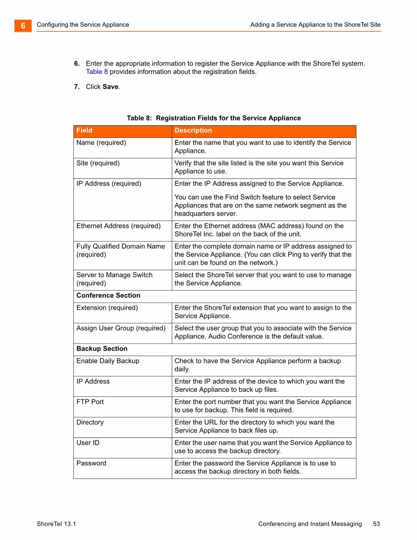
Configuring the Service Appliance Adding a Service Appliance to the ShoreTel Site6
6. Enter the appropriate information to register the Service Appliance with the ShoreTel system. Table 8 provides information about the registration fields.
7. Click Save.
Table 8: Registration Fields for the Service Appliance
Field Description
Name (required) Enter the name that you want to use to identify the Service Appliance.
Site (required) Verify that the site listed is the site you want this Service Appliance to use.
IP Address (required) Enter the IP Address assigned to the Service Appliance.
You can use the Find Switch feature to select Service Appliances that are on the same network segment as the headquarters server.
Ethernet Address (required) Enter the Ethernet address (MAC address) found on the ShoreTel Inc. label on the back of the unit.
Fully Qualified Domain Name (required)
Enter the complete domain name or IP address assigned to the Service Appliance. (You can click Ping to verify that the unit can be found on the network.)
Server to Manage Switch (required)
Select the ShoreTel server that you want to use to manage the Service Appliance.
Conference Section
Extension (required) Enter the ShoreTel extension that you want to assign to the Service Appliance.
Assign User Group (required) Select the user group that you to associate with the Service Appliance. Audio Conference is the default value.
Backup Section
Enable Daily Backup Check to have the Service Appliance perform a backup daily.
IP Address Enter the IP address of the device to which you want the Service Appliance to back up files.
FTP Port Enter the port number that you want the Service Appliance to use for backup. This field is required.
Directory Enter the URL for the directory to which you want the Service Appliance to back files up.
User ID Enter the user name that you want the Service Appliance to use to access the backup directory.
Password Enter the password the Service Appliance is to use to access the backup directory in both fields.
ShoreTel 13.1 Conferencing and Instant Messaging 53
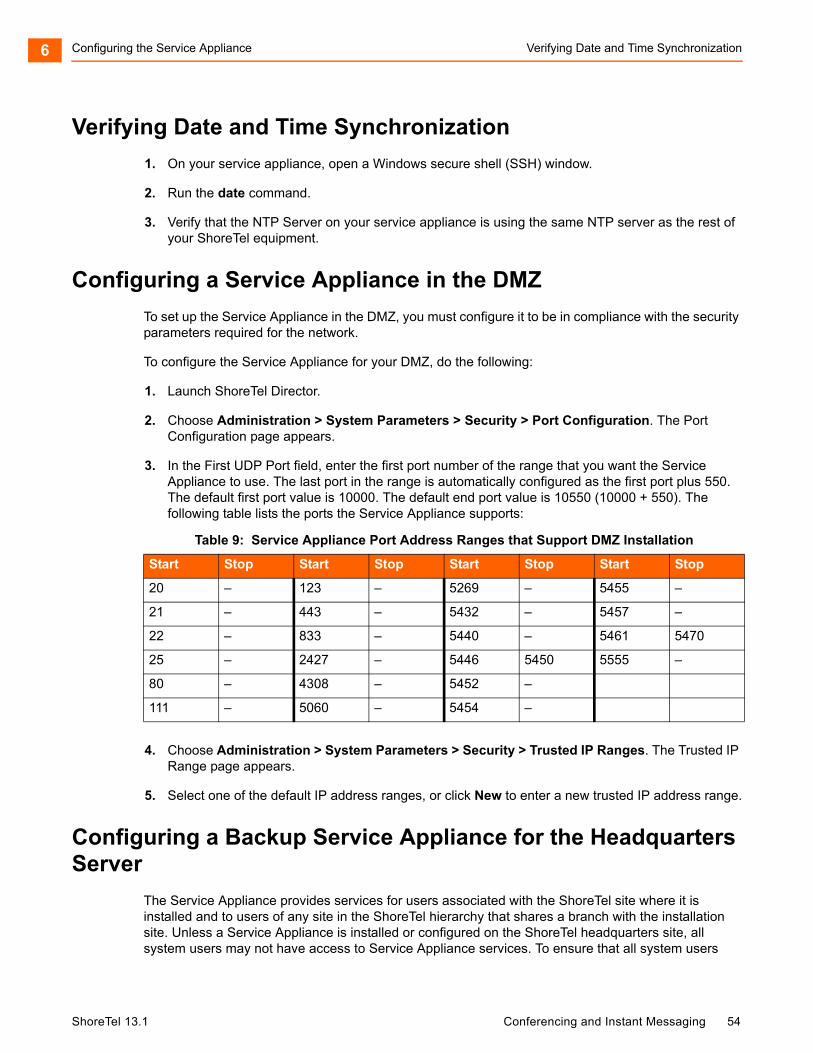
Configuring the Service Appliance Verifying Date and Time Synchronization6
Verifying Date and Time Synchronization
1. On your service appliance, open a Windows secure shell (SSH) window.
2. Run the date command.
3. Verify that the NTP Server on your service appliance is using the same NTP server as the rest of your ShoreTel equipment.
Configuring a Service Appliance in the DMZ
To set up the Service Appliance in the DMZ, you must configure it to be in compliance with the security parameters required for the network.
To configure the Service Appliance for your DMZ, do the following:
1. Launch ShoreTel Director.
2. Choose Administration > System Parameters > Security > Port Configuration. The Port Configuration page appears.
3. In the First UDP Port field, enter the first port number of the range that you want the Service Appliance to use. The last port in the range is automatically configured as the first port plus 550. The default first port value is 10000. The default end port value is 10550 (10000 + 550). The following table lists the ports the Service Appliance supports:
4. Choose Administration > System Parameters > Security > Trusted IP Ranges. The Trusted IP Range page appears.
5. Select one of the default IP address ranges, or click New to enter a new trusted IP address range.
Configuring a Backup Service Appliance for the Headquarters Server
The Service Appliance provides services for users associated with the ShoreTel site where it is installed and to users of any site in the ShoreTel hierarchy that shares a branch with the installation site. Unless a Service Appliance is installed or configured on the ShoreTel headquarters site, all system users may not have access to Service Appliance services. To ensure that all system users
Table 9: Service Appliance Port Address Ranges that Support DMZ Installation
Start Stop Start Stop Start Stop Start Stop
20 – 123 – 5269 – 5455 –
21 – 443 – 5432 – 5457 –
22 – 833 – 5440 – 5461 5470
25 – 2427 – 5446 5450 5555 –
80 – 4308 – 5452 –
111 – 5060 – 5454 –
ShoreTel 13.1 Conferencing and Instant Messaging 54
Configuring the Service Appliance Setting Up a Service Appliance to Remote Service Appliances6
have access to Service Appliance services when there is no unit installed on the headquarters site, you can configure a backup site containing a Service Appliance for the headquarters server. Configuring the backup site with the headquarters server establishes a hierarchical branch that allows all users throughout the system access to Service Appliance services.
To configure a backup Service Appliance site on the headquarters server, follow these steps:
1. Launch ShoreTel Director.
2. Click Administration > Sites. The Sites page appears.
3. In the Site column, select headquarters site. The configuration page for the headquarters site appears.
4. In the Service Appliance Conference Backup Site field, select a site.
5. The backup site can be a logical site.
6. Click Save.
Setting Up a Service Appliance to Remote Service Appliances
Content for conference web pages is managed by the headquarters server but distributed to endpoints through the local Service Appliances. When updates occur in the conference viewer, the updates are first sent to the Service Appliance, which then distributes them to the endpoints for viewing. Situations where distance or network robustness cause network latency to exceed 100 ms between the headquarters server and the Service Appliance can make rendering objects on the endpoints very slow. One possible remedy is to use a Service Appliance closer to the headquarters server as a web-portal proxy for the distant Service Appliance.
Because the proxy is closer to the source, the latency that occurs between the headquarters server and remote Service Appliances is eliminated allowing web pages are rendered quicker. This section describes how to set up a Service Appliance proxy for web portal rendering.
To set up a web portal proxy for a remote Service Appliance, follow these steps:
1. Install a Service Appliance near the headquarters server, so that the latency between the two is under 100 ms.
2. Identify a Service Appliance for which you want to use a proxy web portal.
3. Launch ShoreTel Director.
4. Click Administration > Platform Hardware > Voice Switches/Server Appliances > Primary. The Primary Voice Switches/Server Appliances page appears.
5. Click the Service Appliance for which you want to use the web portal proxy.
6. Check the Is Remote Service Appliance check box.
7. Click Save.
ShoreTel 13.1 Conferencing and Instant Messaging 55
Configuring the Service Appliance Configuring the Conference Viewer Page6
Requests for the web portal by endpoints using this Service Appliance will be redirected to the proxy portal. If a device is not available to perform the web portal proxy service, the headquarters server will use the remote Service Appliance.
Also, checking the Is Remote Service Appliance check box informs the system not to redirect calls to this Service Appliance for failover purposes.
Configuring the Conference Viewer Page
A ShoreTel Director user with administration privileges can customize the conference viewer page that the Service Appliance generates. The administrator can change the logo that appears, place a link behind the logo that redirects the user to another site, and change the name that appears on the page.
If you access the conference viewer from a PC running Windows Server, ensure that your browser allows JavaScript to download. JavaScript is required to render the conference viewer.
To customize the conference web page for the Service Appliance, follow these steps:
1. Log in to ShoreTel Director as an administrator with privileges to access the Launch button for the Service Appliance. You can create this administrator account as follows:
a. Using Director, create a new user on the headquarters server whose client ID is admin.
b. Assign system administrator privileges to the new user account you created.
c. Log in to Director using the new administrator account you crated.
2. Choose Administration > Platform Hardware > Voice Switches/Service Appliances > Primary. The Primary Voice Switches/ Service Appliance page appears.
3. Locate the Service Appliance for which you want to modify the conference viewer page and click Launch in the Quick Launch column. The Service Appliance Conference Administration page appears.
4. Click Website. The Website page appears, as shown in Figure 12.
5. In the Web Site Logo field, enter the path to the logo that you want to appear on web conference pages.
6. To specify the link that you want to associate with the web site logo:
a. Select the Link to the Home page radio button to connect users to the conference home page when they click on the logo.
Note
You must create an administrator user account in ShoreTel Director to access the page that lets you configure conference web page. You cannot use the default user ID and password (admin and changeme) to access this page.
ShoreTel 13.1 Conferencing and Instant Messaging 56
Configuring the Service Appliance Configuring the Conference Viewer Page6
b. Select the Custom link radio button and enter the path to the destination that you want users to go to when they click on the logo.
7. In the Window Title field, enter the name that you want to use as the identifier for conferences managed by this Service Appliance. The name will appear on the browser tab of active conferences. The default name is ShoreTel Conference.
8. To create footers that appear at the bottom of the conference web page, follow these steps:
a. In a Footer Label field, enter the name that you want to appear as a footer at the bottom of conference web pages.
b. Click Submit to create the footer. The page refreshes.
c. Click Edit page next to the footer label for which you want to provide text. The “Edit footer name” page appears.
d. Enter the text that you want to appear when a user clicks the footer. You can use HTML text to populate the field.
e. Click Submit. The page refreshes.
f. The footer will appear on the bar at the bottom of the conference web page. Users can access the message by clicking the footer label.
9. To remove a footer, erase the footer label and click Submit.
10. Click Submit to save your changes.
The remaining fields are not used.
ShoreTel 13.1 Conferencing and Instant Messaging 57
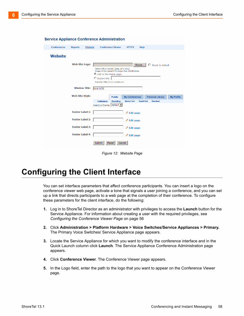
Configuring the Service Appliance Configuring the Client Interface6
Figure 12: Website Page
Configuring the Client Interface
You can set interface parameters that affect conference participants. You can insert a logo on the conference viewer web page, activate a tone that signals a user joining a conference, and you can set up a link that directs participants to a web page at the completion of their conference. To configure these parameters for the client interface, do the following:
1. Log in to ShoreTel Director as an administrator with privileges to access the Launch button for the Service Appliance. For information about creating a user with the required privileges, see Configuring the Conference Viewer Page on page 56
2. Click Administration > Platform Hardware > Voice Switches/Service Appliances > Primary. The Primary Voice Switches/ Service Appliance page appears.
3. Locate the Service Appliance for which you want to modify the conference interface and in the Quick Launch column click Launch. The Service Appliance Conference Administration page appears.
4. Click Conference Viewer. The Conference Viewer page appears.
5. In the Logo field, enter the path to the logo that you want to appear on the Conference Viewer page.
ShoreTel 13.1 Conferencing and Instant Messaging 58
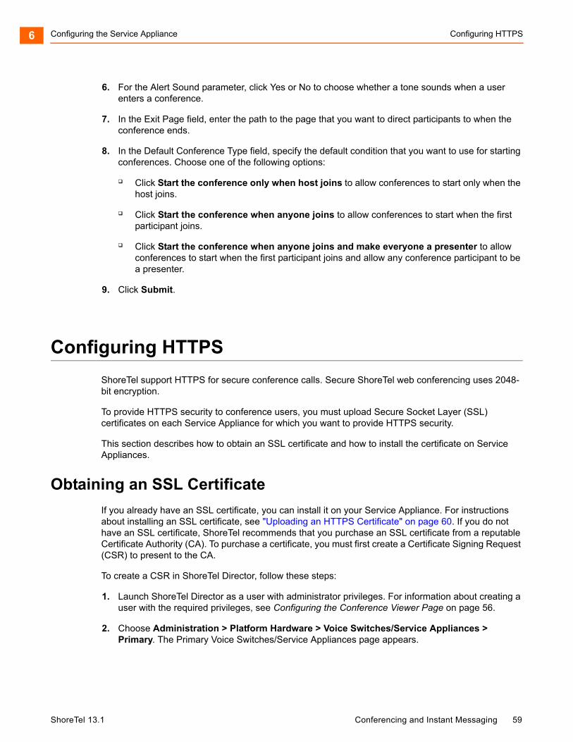
Configuring the Service Appliance Configuring HTTPS6
6. For the Alert Sound parameter, click Yes or No to choose whether a tone sounds when a user enters a conference.
7. In the Exit Page field, enter the path to the page that you want to direct participants to when the conference ends.
8. In the Default Conference Type field, specify the default condition that you want to use for starting conferences. Choose one of the following options:
Click Start the conference only when host joins to allow conferences to start only when the host joins.
Click Start the conference when anyone joins to allow conferences to start when the first participant joins.
Click Start the conference when anyone joins and make everyone a presenter to allow conferences to start when the first participant joins and allow any conference participant to be a presenter.
9. Click Submit.
Configuring HTTPS
ShoreTel support HTTPS for secure conference calls. Secure ShoreTel web conferencing uses 2048-bit encryption.
To provide HTTPS security to conference users, you must upload Secure Socket Layer (SSL) certificates on each Service Appliance for which you want to provide HTTPS security.
This section describes how to obtain an SSL certificate and how to install the certificate on Service Appliances.
Obtaining an SSL Certificate
If you already have an SSL certificate, you can install it on your Service Appliance. For instructions about installing an SSL certificate, see "Uploading an HTTPS Certificate" on page 60. If you do not have an SSL certificate, ShoreTel recommends that you purchase an SSL certificate from a reputable Certificate Authority (CA). To purchase a certificate, you must first create a Certificate Signing Request (CSR) to present to the CA.
To create a CSR in ShoreTel Director, follow these steps:
1. Launch ShoreTel Director as a user with administrator privileges. For information about creating a user with the required privileges, see Configuring the Conference Viewer Page on page 56.
2. Choose Administration > Platform Hardware > Voice Switches/Service Appliances > Primary. The Primary Voice Switches/Service Appliances page appears.
ShoreTel 13.1 Conferencing and Instant Messaging 59

Configuring the Service Appliance Uploading an HTTPS Certificate6
3. Select a Service Appliance listing and in the Quick Launch column and click Launch. The Service Appliance Conference Administration Conferences page appears.
4. Click the HTTPS tab. The HTTPS tab appears.
5. Enter the HTTPS parameters. For a description of the HTTPS fields, see Table 10.
6. Click Create CSR. The ShoreTel system creates a CSR and a private key.
The system generates links that you can use to download the CSR and private key.
7. Download the CSR and private key, if required, and send them to the CA.
Uploading an HTTPS Certificate
You can upload certificates for a single Service Appliance or for all of the Service Appliances currently installed on your systems depending upon your certificate agreement.
To upload HTTPS certificates, follow these steps:
Note
On the HTTPS tab, an asterisk indicates a required field.
Table 10: HTTPS Fields and Descriptions
Field Description
Country Enter the two-character country code for the country where the system is installed. Refer to ISO 3166 for information about country codes.
State or Province Enter the name of the state or province where the system is installed.
Locality Enter the name of the city where the system is installed.
Organization Enter the legal name of the company or organization or the person that is requesting the certificate.
Organizational Unit Enter the name of the department that is requesting the certificate.
Common Name Enter the Fully Qualified Domain Name (FQDN) for which you want the SSL certificate.
Note: If the CSR is for a wildcard certificate, you must prepend *. to the common name; for example, *.domain.com.
Email Address Enter the email address of the administrator who will handle the certificate.
ShoreTel 13.1 Conferencing and Instant Messaging 60
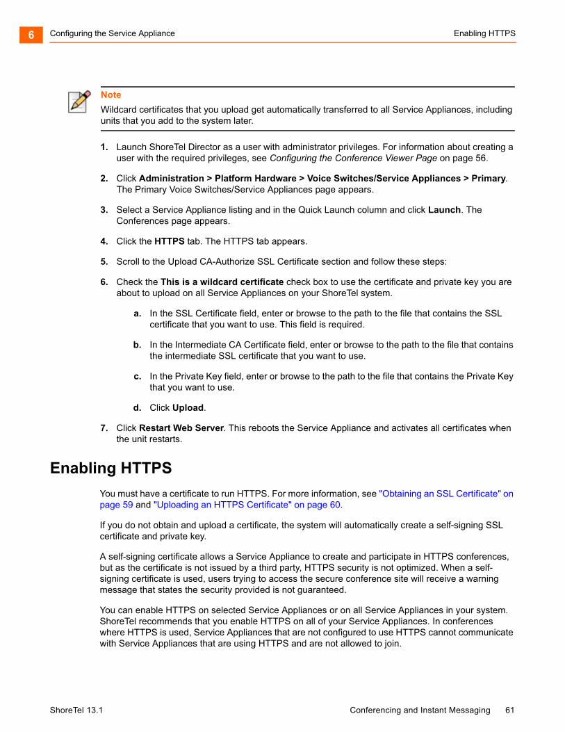
Configuring the Service Appliance Enabling HTTPS6
1. Launch ShoreTel Director as a user with administrator privileges. For information about creating a user with the required privileges, see Configuring the Conference Viewer Page on page 56.
2. Click Administration > Platform Hardware > Voice Switches/Service Appliances > Primary. The Primary Voice Switches/Service Appliances page appears.
3. Select a Service Appliance listing and in the Quick Launch column and click Launch. The Conferences page appears.
4. Click the HTTPS tab. The HTTPS tab appears.
5. Scroll to the Upload CA-Authorize SSL Certificate section and follow these steps:
6. Check the This is a wildcard certificate check box to use the certificate and private key you are about to upload on all Service Appliances on your ShoreTel system.
a. In the SSL Certificate field, enter or browse to the path to the file that contains the SSL certificate that you want to use. This field is required.
b. In the Intermediate CA Certificate field, enter or browse to the path to the file that contains the intermediate SSL certificate that you want to use.
c. In the Private Key field, enter or browse to the path to the file that contains the Private Key that you want to use.
d. Click Upload.
7. Click Restart Web Server. This reboots the Service Appliance and activates all certificates when the unit restarts.
Enabling HTTPS
You must have a certificate to run HTTPS. For more information, see "Obtaining an SSL Certificate" on page 59 and "Uploading an HTTPS Certificate" on page 60.
If you do not obtain and upload a certificate, the system will automatically create a self-signing SSL certificate and private key.
A self-signing certificate allows a Service Appliance to create and participate in HTTPS conferences, but as the certificate is not issued by a third party, HTTPS security is not optimized. When a self-signing certificate is used, users trying to access the secure conference site will receive a warning message that states the security provided is not guaranteed.
You can enable HTTPS on selected Service Appliances or on all Service Appliances in your system. ShoreTel recommends that you enable HTTPS on all of your Service Appliances. In conferences where HTTPS is used, Service Appliances that are not configured to use HTTPS cannot communicate with Service Appliances that are using HTTPS and are not allowed to join.
Note
Wildcard certificates that you upload get automatically transferred to all Service Appliances, including units that you add to the system later.
ShoreTel 13.1 Conferencing and Instant Messaging 61
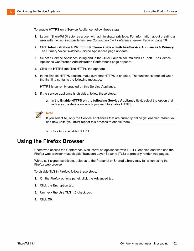
Configuring the Service Appliance Using the Firefox Browser6
To enable HTTPS on a Service Appliance, follow these steps:
1. Launch ShoreTel Director as a user with administrator privilege. For information about creating a user with the required privileges, see Configuring the Conference Viewer Page on page 56.
2. Click Administration > Platform Hardware > Voice Switches/Service Appliances > Primary. The Primary Voice Switches/Service Appliances page appears.
3. Select a Service Appliance listing and in the Quick Launch column click Launch. The Service Appliance Conference Administration Conferences page appears.
4. Click the HTTPS tab. The HTTPS tab appears.
5. In the Enable HTTPS section, make sure that HTTPS is enabled. The function is enabled when the first line contains the following message:
HTTPS is currently enabled on this Service Appliance.
6. If the service appliance is disabled, follow these steps:
a. In the Enable HTTPS on the following Service Appliance field, select the option that indicates the device on which you want to enable HTTPS.
b. Click Go to enable HTTPS.
Using the Firefox Browser
Users who access the Conference Web Portal on appliances with HTTPS enabled and who use the Firefox web browser must disable Transport Layer Security (TLS) to properly render web pages.
With a self-signed certificate, uploads to the Personal or Shared Library may fail when using the Firefox web browser.
To disable TLS in Firefox, follow these steps:
1. On the Firefox options panel, click the Advanced tab.
2. Click the Encryption tab.
3. Uncheck the Use TLS 1.0 check box.
4. Click OK.
Note
If you select All, only the Service Appliances that are currently online get enabled. When you add new units, you must repeat this process to enable them.
ShoreTel 13.1 Conferencing and Instant Messaging 62
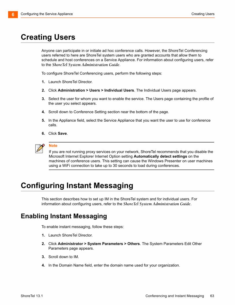
Configuring the Service Appliance Creating Users6
Creating Users
Anyone can participate in or initiate ad hoc conference calls. However, the ShoreTel Conferencing users referred to here are ShoreTel system users who are granted accounts that allow them to schedule and host conferences on a Service Appliance. For information about configuring users, refer to the ShoreTel System Administration Guide.
To configure ShoreTel Conferencing users, perform the following steps:
1. Launch ShoreTel Director.
2. Click Administration > Users > Individual Users. The Individual Users page appears.
3. Select the user for whom you want to enable the service. The Users page containing the profile of the user you select appears.
4. Scroll down to Conference Setting section near the bottom of the page.
5. In the Appliance field, select the Service Appliance that you want the user to use for conference calls.
6. Click Save.
Configuring Instant Messaging
This section describes how to set up IM in the ShoreTel system and for individual users. For information about configuring users, refer to the ShoreTel System Administration Guide.
Enabling Instant Messaging
To enable instant messaging, follow these steps:
1. Launch ShoreTel Director.
2. Click Administrator > System Parameters > Others. The System Parameters Edit Other Parameters page appears.
3. Scroll down to IM.
4. In the Domain Name field, enter the domain name used for your organization.
Note
If you are not running proxy services on your network, ShoreTel recommends that you disable the Microsoft Internet Explorer Internet Option setting Automatically detect settings on the machines of conference users. This setting can cause the Windows Presenter on user machines using a WiFi connection to take up to 30 seconds to load during conferences.
ShoreTel 13.1 Conferencing and Instant Messaging 63
Configuring the Service Appliance Configuring the IM Class of Service6
5. Check the Enable Offline Message checkbox if you want to allow users to leave messages for IM users who logged in that the logged off user can get when they log in.
6. In the Sessions Timeout field, enter the duration, in minutes, that you want the system to keep an IM session open without an exchange before timing out.
7. Click Save.
Configuring the IM Class of Service
To configure the IM class of service, follow these steps:
1. Launch ShoreTel Director.
2. Click Administration > Users > Class of Service. The Class of Service page appears.
3. In the Telephony Features Permissions section, select the feature class to which you want to add IM services. The Users page containing the profile of the user you selected appears.
4. In the IM Presence Invitation Handling field, select one of the following options:
User defined: Allows the user to choose how to handle IM invitations.
Auto accept invitation: Forces IM invitations to be accepted automatically. Invitee still must invite inviter.
Prompt to accept invitation: User is prompted when a new invitation is issued.
5. Click Save.
Configuring IM
To configure IM, follow these steps:
1. Launch ShoreTel Director.
2. Click Administration > Users > Individual Users. The Individual Users page appears.
3. Select the user for whom you want to enable the service. The Users page containing the profile of the user you selected appears.
4. Scroll down to Instant Messaging Settings section near the bottom of the page.
5. In the Server/Appliance field, select the Service Appliance that you want the user to use for IM.
6. In the Presence Invitation Handling field, select one of the following options:
Note
If you are using an SSL certificate, check the Enable TLS checkbox to allow users to encrypt IM messages using Transport Layer Security (TLS) protocol.
ShoreTel 13.1 Conferencing and Instant Messaging 64
Configuring the Service Appliance Migrating IM and Presence Users to a Service Appliance6
Select Auto accept invitation to have the system automatically accept a presence invitation for the user.
Select Prompt to accept invitation to have the system issue a prompt to the user when another user sends a presence invitation.
Migrating IM and Presence Users to a Service Appliance
To move IM and Presence users from a legacy ShoreTel IM Server to a Service Appliance, follow these steps:
1. Launch ShoreTel Director.
2. Click Administration > Users > Individual Users. The Individual Users page appears.
3. Select the user that you want to move to the Service Appliance. The Users page appears.
4. Locate the Instant Messaging Settings section and in the Server/Appliance field, select the Service Appliance that you want the user to use for IM and Presence.
5. Click Save.
6. Notify the end-user to uninstall, then install Outlook calendar integration in ShoreTel Communicator for Windows if they are using Outlook calendar-integration. Refer to ShoreTel 12: Communicator for Windows User Guide for instruction on how to configure Outlook calendar integration.
Connecting with the Microsoft Exchange Server
ShoreTel provides an add-in that allows users to integrate Microsoft Outlook Calendar with ShoreTel conferencing. When the user installs the add-in, the ShoreTel tab appears in the appointment window of the Microsoft Outlook calendar, which allows the user to create meetings that have ShoreTel conferencing parameters. Information about conferences users create is stored in the ShoreTel database for the service appliance and used to update the conference user interface. Users can edit, delete, and make exceptions to the conferences that they create in Outlook. These changes are also uploaded to the database and used to update the conference user interface.
The connector ShoreTel uses to connect Service Appliances with the Microsoft Exchange server is built into the ShoreTel server software and implemented through ShoreTel Director.
Note
The Presence Invitation Handling field only appears when a Service Appliance is enabled for the user and the IM Presence Invitation Handling parameter in the Class of Service profile used for user group to which the user is associated with is configured to allow the user to make this selection.
ShoreTel 13.1 Conferencing and Instant Messaging 65
Configuring the Service Appliance Enforced Scheduling6
The connector is designed to allow one service appliance to serve as intermediary for all of the others. This unit will poll the Exchange server periodically and maintain the connection between the server and the ShoreTel system, which will update the other appliances as required. Data about the Exchange synchronization polling appears in the Service Appliance Maintenance page for this unit only.
After the connector is installed and users are using the feature, the connector allows the system to poll the Exchange server for updates to existing conferences. Conference data that has changed in Outlook Calendar is updated in the Conference Web Portal. New conferences are not added to the ShoreTel database during polling, but about the time they are created in Outlook Calendar. Polling intervals are based on the number of Outlook Calendar users your system supports. For every 500 users, the system adds 30 minutes to the polling interval. For example, for systems that have 500 users the polling interval is every 30 minutes. For systems that have up to 1000 users the polling interval is 60 minutes. For systems that have 5001 users the polling interval is 720 minutes (12 hours).
Enforced Scheduling
This optional feature provides enforced scheduling for conferences that allows participants to join without the presence of the host. For conferences with enforced scheduling, participants who join within five minutes of the scheduled start time and before the host joins receive a prompt that the conference has not started and are placed in a wait state until the conference starts. The conference starts when the host joins or, when the host does not join, at the scheduled time.
The scheduled end of a conference session is also enforced when the host does not join the conference. Participants in a conference in which the host does not join are prompted ten minutes before the conference is scheduled to end that the conference will end. The conference is automatically terminated at the scheduled time. If the host joins at any time during the conference, scheduling is not enforced.
Enforced scheduling is enabled for conferences that do not require host attendance. Conference creators can configure their conferences to require a host, the default setting is for conferences not to require a host.
Enabling the ShoreTel Connector to Microsoft Exchange
You can use the ShoreTel connector for Exchange Server with one Exchange Server only. Connections with multiple Exchange Servers are not supported.
If you are upgrading or migrating the Exchange Server and have multiple Exchange Servers, ShoreTel recommends that you disable the Exchange connector before you start the upgrade or migration.
Before you enable the ShoreTel Connector, ensure your system satisfies the following requirements:
Exchange user for ShoreTel conferencing. This must be a privileged user able to query data for other Exchange users.
Microsoft Exchange Server 2010 or Exchange Server 2007 SP1.
Note
Use of the Outlook add-in is not dependent upon Exchange Server integration.
ShoreTel 13.1 Conferencing and Instant Messaging 66
Configuring the Service Appliance Enabling the ShoreTel Connector to Microsoft Exchange6
Exchange e-mail address for end users.
To enable the ShoreTel Connector for Microsoft Exchange, follow these steps:
1. Launch ShoreTel Director as a user with administrator privilege. For information about creating a user with the required privileges, see Configuring the Conference Viewer Page on page 56.
2. Click Administration > System Parameters > Other. The Edit Other Parameters page appears.
3. In the Service Appliance section, check the Enable Exchange Connector checkbox.
4. In the Exchange Server field, enter the URL of the Exchange Server. (You can also use the IP address.) To verify that the address is correct, click Ping.
5. In the Username field, enter the user name used for the mailbox created on the Microsoft Exchange server for ShoreTel Conferencing.
6. In the Password field, enter the password required for the user to access the ShoreTel conferencing mailbox.
7. Click Save.
8. Click Administration > User > Individual Users. The Individual Users page appears.
9. Select a user that you want to allow to synchronize their ShoreTel conference schedule with Outlook. The Edit User page appears.
10. Scroll down to Email Address and enter the Microsoft Exchange Primary SMTP Address assigned to the user.
11. In the Appliance field in the Conference Settings section, select the Service Appliance that you want the user to use.
12. Click Save.
Conference sessions are reported in both Microsoft Outlook calendar and the conference page for the user on the ShoreTel Conferencing Website.
Note
The connector uses the Primary SMTP Address of the user to authenticate access to the Exchange Server. If the user or an administrator changes the e-mail address, the connector will not be able to access the account of the user, and the user will not be able to synchronize Outlook with the Service Appliance.
ShoreTel 13.1 Conferencing and Instant Messaging 67
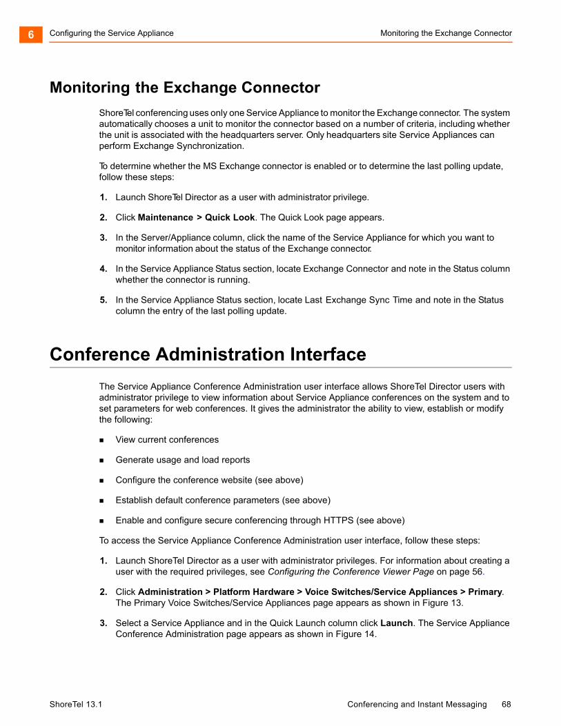
Configuring the Service Appliance Monitoring the Exchange Connector6
Monitoring the Exchange Connector
ShoreTel conferencing uses only one Service Appliance to monitor the Exchange connector. The system automatically chooses a unit to monitor the connector based on a number of criteria, including whether the unit is associated with the headquarters server. Only headquarters site Service Appliances can perform Exchange Synchronization.
To determine whether the MS Exchange connector is enabled or to determine the last polling update, follow these steps:
1. Launch ShoreTel Director as a user with administrator privilege.
2. Click Maintenance > Quick Look. The Quick Look page appears.
3. In the Server/Appliance column, click the name of the Service Appliance for which you want to monitor information about the status of the Exchange connector.
4. In the Service Appliance Status section, locate Exchange Connector and note in the Status column whether the connector is running.
5. In the Service Appliance Status section, locate Last Exchange Sync Time and note in the Status column the entry of the last polling update.
Conference Administration Interface
The Service Appliance Conference Administration user interface allows ShoreTel Director users with administrator privilege to view information about Service Appliance conferences on the system and to set parameters for web conferences. It gives the administrator the ability to view, establish or modify the following:
View current conferences
Generate usage and load reports
Configure the conference website (see above)
Establish default conference parameters (see above)
Enable and configure secure conferencing through HTTPS (see above)
To access the Service Appliance Conference Administration user interface, follow these steps:
1. Launch ShoreTel Director as a user with administrator privileges. For information about creating a user with the required privileges, see Configuring the Conference Viewer Page on page 56.
2. Click Administration > Platform Hardware > Voice Switches/Service Appliances > Primary. The Primary Voice Switches/Service Appliances page appears as shown in Figure 13.
3. Select a Service Appliance and in the Quick Launch column click Launch. The Service Appliance Conference Administration page appears as shown in Figure 14.
ShoreTel 13.1 Conferencing and Instant Messaging 68
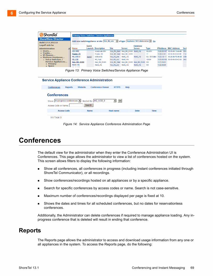
Configuring the Service Appliance Conferences6
Figure 13: Primary Voice Switches/Service Appliance Page
Figure 14: Service Appliance Conference Administration Page
Conferences
The default view for the administrator when they enter the Conference Administration UI is Conferences. This page allows the administrator to view a list of conferences hosted on the system. This screen allows filters to display the following information:
Show all conferences, all conferences in progress (including instant conferences initiated through ShoreTel Communicator), or all recordings.
Show conferences/recordings hosted on all appliances or by a specific appliance.
Search for specific conferences by access codes or name. Search is not case-sensitive.
Maximum number of conferences/recordings displayed per page is fixed at 10.
Shows the dates and times for all scheduled conferences, but no dates for reservationless conferences.
Additionally, the Administrator can delete conferences if required to manage appliance loading. Any in-progress conference that is deleted will result in ending that conference.
Reports
The Reports page allows the administrator to access and download usage information from any one or all appliances in the system. To access the Reports page, do the following:
ShoreTel 13.1 Conferencing and Instant Messaging 69
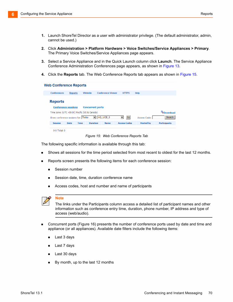
Configuring the Service Appliance Reports6
1. Launch ShoreTel Director as a user with administrator privilege. (The default administrator, admin, cannot be used.)
2. Click Administration > Platform Hardware > Voice Switches/Service Appliances > Primary. The Primary Voice Switches/Service Appliances page appears.
3. Select a Service Appliance and in the Quick Launch column click Launch. The Service Appliance Conference Administration Conferences page appears, as shown in Figure 13.
4. Click the Reports tab. The Web Conference Reports tab appears as shown in Figure 15.
Figure 15: Web Conference Reports Tab
The following specific information is available through this tab:
Shows all sessions for the time period selected from most recent to oldest for the last 12 months.
Reports screen presents the following items for each conference session:
Session number
Session date, time, duration conference name
Access codes, host and number and name of participants
Concurrent ports (Figure 16) presents the number of conference ports used by date and time and appliance (or all appliances). Available date filters include the following items:
Last 3 days
Last 7 days
Last 30 days
By month, up to the last 12 months
Note
The links under the Participants column access a detailed list of participant names and other information such as conference entry time, duration, phone number, IP address and type of access (web/audio).
ShoreTel 13.1 Conferencing and Instant Messaging 70
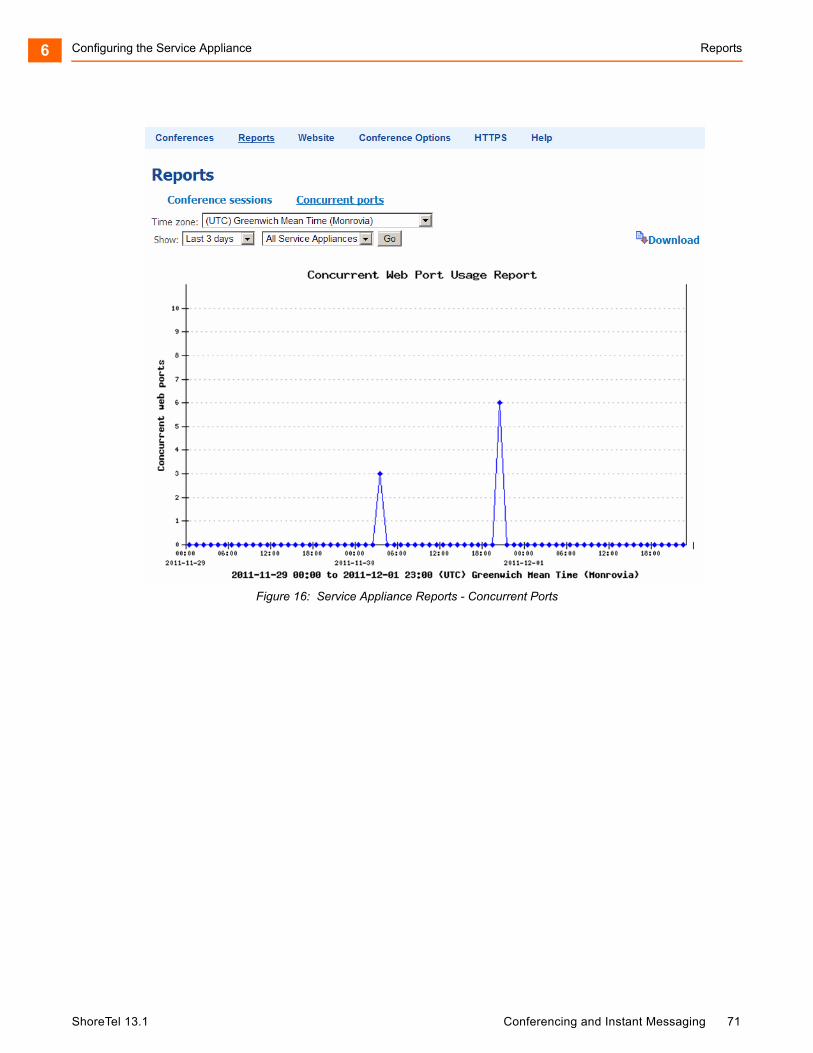
Configuring the Service Appliance Reports6
Figure 16: Service Appliance Reports - Concurrent Ports
ShoreTel 13.1 Conferencing and Instant Messaging 71
CHAPTER
7. Maintenance
ShoreTel Director provides operational maintenance information for all appliances as well as switches, ports, servers and services.
This section summarizes information available regarding the Service Appliance 100. For detailed explanations of maintenance options for all system components see the ShoreTel System Administration Guide and ShoreTel Maintenance Guide.
Topics discussed include:
Quick Look ................................................................................................................ 73
Viewing System Information...................................................................................... 74
Viewing Audio and Web Conferencing Activity ......................................................... 80
Viewing the IM Servers Maintenance Summary ....................................................... 81
ShoreTel 13.1 Conferencing and Instant Messaging 72
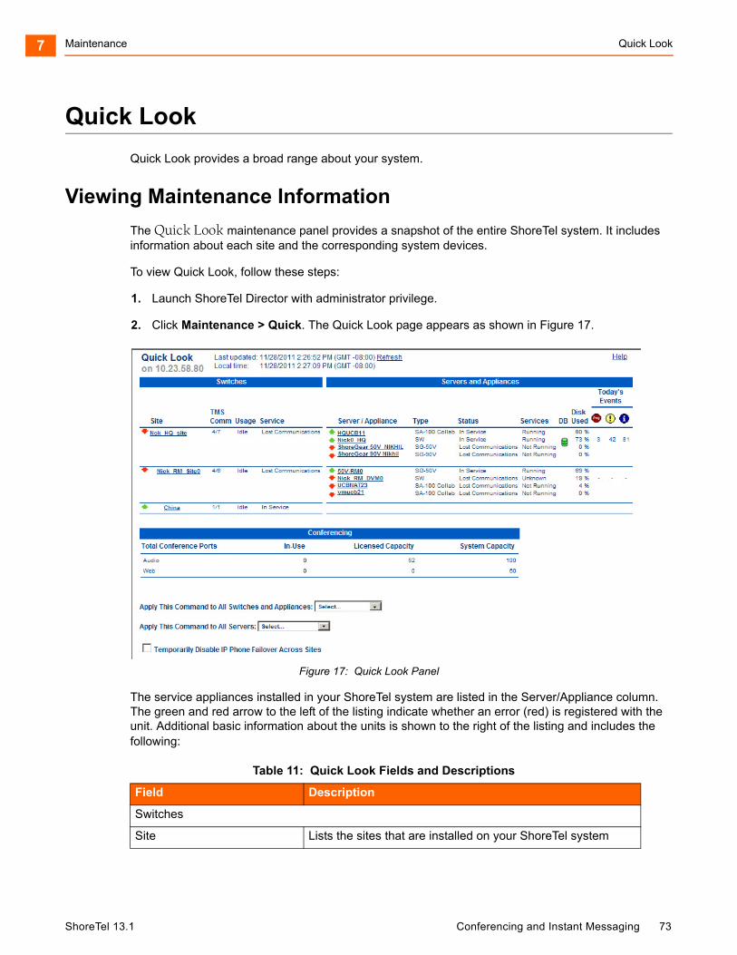
Maintenance Quick Look7
Quick Look
Quick Look provides a broad range about your system.
Viewing Maintenance Information
The Quick Look maintenance panel provides a snapshot of the entire ShoreTel system. It includes information about each site and the corresponding system devices.
To view Quick Look, follow these steps:
1. Launch ShoreTel Director with administrator privilege.
2. Click Maintenance > Quick. The Quick Look page appears as shown in Figure 17.
Figure 17: Quick Look Panel
The service appliances installed in your ShoreTel system are listed in the Server/Appliance column. The green and red arrow to the left of the listing indicate whether an error (red) is registered with the unit. Additional basic information about the units is shown to the right of the listing and includes the following:
Table 11: Quick Look Fields and Descriptions
Field Description
Switches
Site Lists the sites that are installed on your ShoreTel system
ShoreTel 13.1 Conferencing and Instant Messaging 73
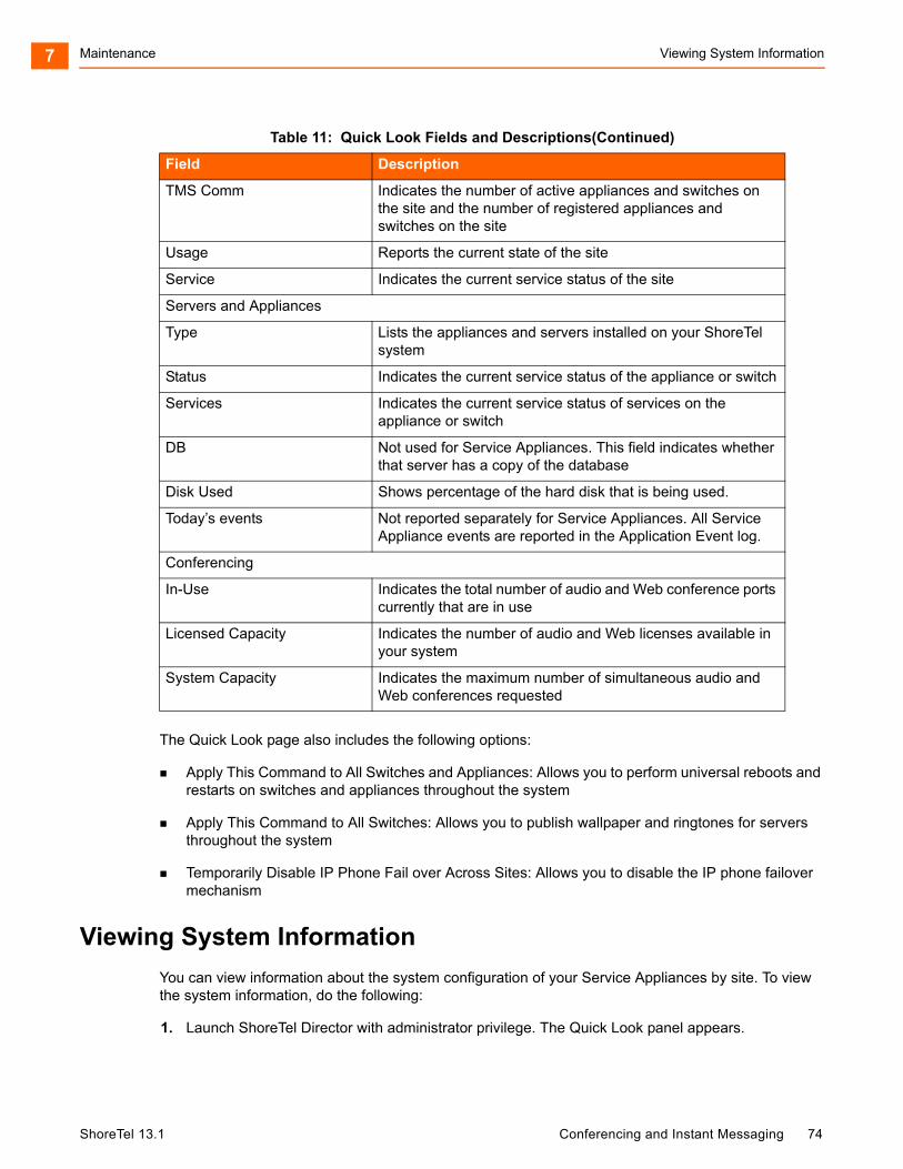
Maintenance Viewing System Information7
The Quick Look page also includes the following options:
Apply This Command to All Switches and Appliances: Allows you to perform universal reboots and restarts on switches and appliances throughout the system
Apply This Command to All Switches: Allows you to publish wallpaper and ringtones for servers throughout the system
Temporarily Disable IP Phone Fail over Across Sites: Allows you to disable the IP phone failover mechanism
Viewing System Information
You can view information about the system configuration of your Service Appliances by site. To view the system information, do the following:
1. Launch ShoreTel Director with administrator privilege. The Quick Look panel appears.
TMS Comm Indicates the number of active appliances and switches on the site and the number of registered appliances and switches on the site
Usage Reports the current state of the site
Service Indicates the current service status of the site
Servers and Appliances
Type Lists the appliances and servers installed on your ShoreTel system
Status Indicates the current service status of the appliance or switch
Services Indicates the current service status of services on the appliance or switch
DB Not used for Service Appliances. This field indicates whether that server has a copy of the database
Disk Used Shows percentage of the hard disk that is being used.
Today’s events Not reported separately for Service Appliances. All Service Appliance events are reported in the Application Event log.
Conferencing
In-Use Indicates the total number of audio and Web conference ports currently that are in use
Licensed Capacity Indicates the number of audio and Web licenses available in your system
System Capacity Indicates the maximum number of simultaneous audio and Web conferences requested
Table 11: Quick Look Fields and Descriptions(Continued)
Field Description
ShoreTel 13.1 Conferencing and Instant Messaging 74
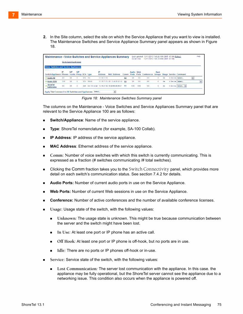
Maintenance Viewing System Information7
2. In the Site column, select the site on which the Service Appliance that you want to view is installed. The Maintenance Switches and Service Appliance Summary panel appears as shown in Figure 18.
Figure 18: Maintenance Switches Summary panel
The columns on the Maintenance - Voice Switches and Service Appliances Summary panel that are relevant to the Service Appliance 100 are as follows:
Switch/Appliance: Name of the service appliance.
Type: ShoreTel nomenclature (for example, SA-100 Collab).
IP Address: IP address of the service appliance.
MAC Address: Ethernet address of the service appliance.
Comm: Number of voice switches with which this switch is currently communicating. This is expressed as a fraction (# switches communicating /# total switches).
Clicking the Comm fraction takes you to the Switch Connectivity panel, which provides more detail on each switch’s communication status. See section 7.4.2 for details.
Audio Ports: Number of current audio ports in use on the Service Appliance.
Web Ports: Number of current Web sessions in use on the Service Appliance.
Conference: Number of active conferences and the number of available conference licenses.
Usage: Usage state of the switch, with the following values:
Unknown: The usage state is unknown. This might be true because communication between the server and the switch might have been lost.
In Use: At least one port or IP phone has an active call.
Off Hook: At least one port or IP phone is off-hook, but no ports are in use.
Idle: There are no ports or IP phones off-hook or in-use.
Service: Service state of the switch, with the following values:
Lost Communication: The server lost communication with the appliance. In this case. the appliance may be fully operational, but the ShoreTel server cannot see the appliance due to a networking issue. This condition also occurs when the appliance is powered off.
ShoreTel 13.1 Conferencing and Instant Messaging 75
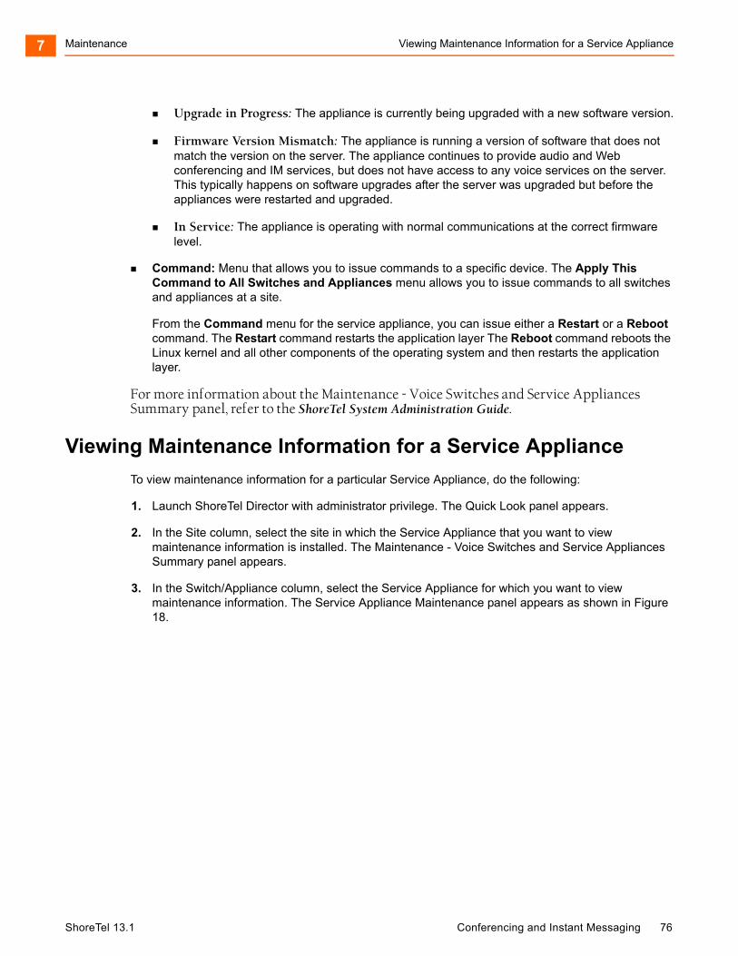
Maintenance Viewing Maintenance Information for a Service Appliance7
Upgrade in Progress: The appliance is currently being upgraded with a new software version.
Firmware Version Mismatch: The appliance is running a version of software that does not match the version on the server. The appliance continues to provide audio and Web conferencing and IM services, but does not have access to any voice services on the server. This typically happens on software upgrades after the server was upgraded but before the appliances were restarted and upgraded.
In Service: The appliance is operating with normal communications at the correct firmware level.
Command: Menu that allows you to issue commands to a specific device. The Apply This Command to All Switches and Appliances menu allows you to issue commands to all switches and appliances at a site.
From the Command menu for the service appliance, you can issue either a Restart or a Reboot command. The Restart command restarts the application layer The Reboot command reboots the Linux kernel and all other components of the operating system and then restarts the application layer.
For more information about the Maintenance - Voice Switches and Service Appliances Summary panel, refer to the ShoreTel System Administration Guide.
Viewing Maintenance Information for a Service Appliance
To view maintenance information for a particular Service Appliance, do the following:
1. Launch ShoreTel Director with administrator privilege. The Quick Look panel appears.
2. In the Site column, select the site in which the Service Appliance that you want to view maintenance information is installed. The Maintenance - Voice Switches and Service Appliances Summary panel appears.
3. In the Switch/Appliance column, select the Service Appliance for which you want to view maintenance information. The Service Appliance Maintenance panel appears as shown in Figure 18.
ShoreTel 13.1 Conferencing and Instant Messaging 76
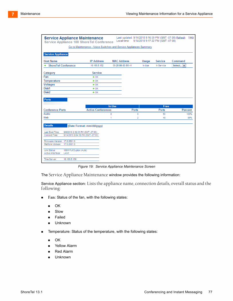
Maintenance Viewing Maintenance Information for a Service Appliance7
Figure 19: Service Appliance Maintenance Screen
The Service Appliance Maintenance window provides the following information:
Service Appliance section: Lists the appliance name, connection details, overall status and the following:
Fan: Status of the fan, with the following states:
OK
Slow
Failed
Unknown
Temperature: Status of the temperature, with the following states:
OK
Yellow Alarm
Red Alarm
Unknown
ShoreTel 13.1 Conferencing and Instant Messaging 77
Maintenance Viewing Current Conference Activity Information7
Voltages: Status of the internal voltages, with the following states:
OK
Failed
Unknown
Ports section: Lists all ports in use and free for both audio and Web conferencing.
Details section: Lists the following additional information:
Last Boot Time: The last time the appliance booted.
Connect Time: The last time the server re-established a connection with the appliance.
Firmware Version: The application firmware version currently running on the appliance.
Platform Version: The operating system version currently running on the appliance.
Link Status: The rate at which the voice switch negotiated the Ethernet interface.
Active Interface: Which LAN port is currently being used.
Time Server: The address of the NTP server.
Viewing Current Conference Activity Information
To view information about Web conference and IM activity for a Service Appliance, follow these steps:
1. Launch ShoreTel Director with administrator privilege. The Quick Look panel appears.
2. In the Server/Appliance column, select the site in which the Service Appliance that you want to view is installed. The ShoreTel Conference panel appears as shown in Figure 20.
ShoreTel 13.1 Conferencing and Instant Messaging 78
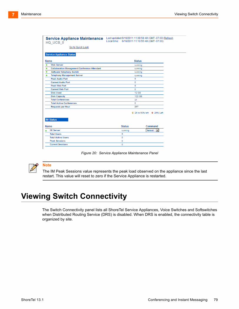
Maintenance Viewing Switch Connectivity7
Figure 20: Service Appliance Maintenance Panel
Viewing Switch Connectivity
The Switch Connectivity panel lists all ShoreTel Service Appliances, Voice Switches and Softswitches when Distributed Routing Service (DRS) is disabled. When DRS is enabled, the connectivity table is organized by site.
Note
The IM Peak Sessions value represents the peak load observed on the appliance since the last restart. This value will reset to zero if the Service Appliance is restarted.
ShoreTel 13.1 Conferencing and Instant Messaging 79
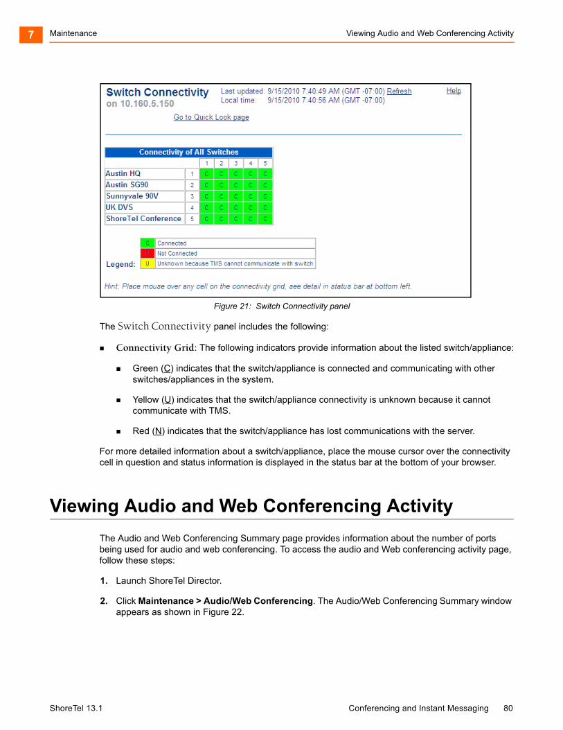
Maintenance Viewing Audio and Web Conferencing Activity7
Figure 21: Switch Connectivity panel
The Switch Connectivity panel includes the following:
Connectivity Grid: The following indicators provide information about the listed switch/appliance:
Green (C) indicates that the switch/appliance is connected and communicating with other switches/appliances in the system.
Yellow (U) indicates that the switch/appliance connectivity is unknown because it cannot communicate with TMS.
Red (N) indicates that the switch/appliance has lost communications with the server.
For more detailed information about a switch/appliance, place the mouse cursor over the connectivity cell in question and status information is displayed in the status bar at the bottom of your browser.
Viewing Audio and Web Conferencing Activity
The Audio and Web Conferencing Summary page provides information about the number of ports being used for audio and web conferencing. To access the audio and Web conferencing activity page, follow these steps:
1. Launch ShoreTel Director.
2. Click Maintenance > Audio/Web Conferencing. The Audio/Web Conferencing Summary window appears as shown in Figure 22.
ShoreTel 13.1 Conferencing and Instant Messaging 80
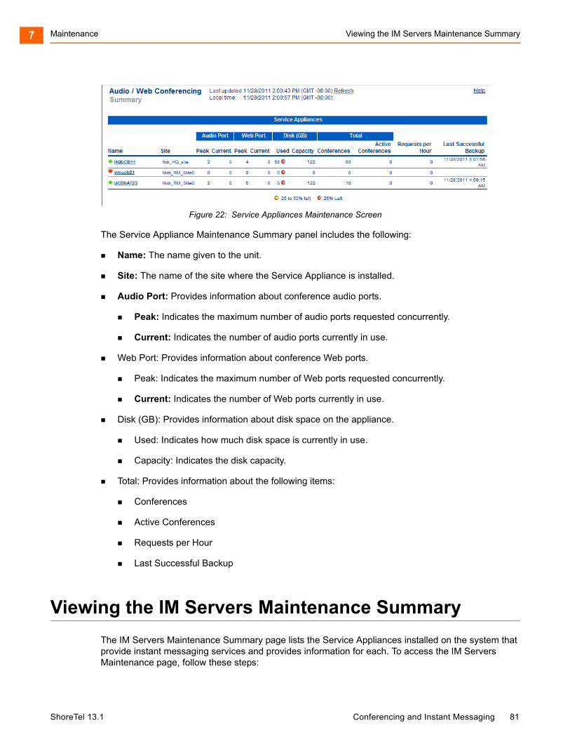
Maintenance Viewing the IM Servers Maintenance Summary7
Figure 22: Service Appliances Maintenance Screen
The Service Appliance Maintenance Summary panel includes the following:
Name: The name given to the unit.
Site: The name of the site where the Service Appliance is installed.
Audio Port: Provides information about conference audio ports.
Peak: Indicates the maximum number of audio ports requested concurrently.
Current: Indicates the number of audio ports currently in use.
Web Port: Provides information about conference Web ports.
Peak: Indicates the maximum number of Web ports requested concurrently.
Current: Indicates the number of Web ports currently in use.
Disk (GB): Provides information about disk space on the appliance.
Used: Indicates how much disk space is currently in use.
Capacity: Indicates the disk capacity.
Total: Provides information about the following items:
Conferences
Active Conferences
Requests per Hour
Last Successful Backup
Viewing the IM Servers Maintenance Summary
The IM Servers Maintenance Summary page lists the Service Appliances installed on the system that provide instant messaging services and provides information for each. To access the IM Servers Maintenance page, follow these steps:
ShoreTel 13.1 Conferencing and Instant Messaging 81
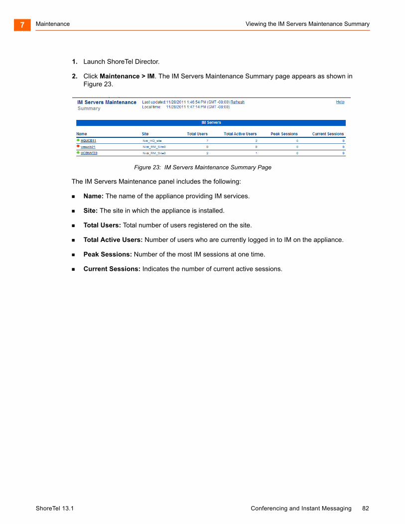
Maintenance Viewing the IM Servers Maintenance Summary7
1. Launch ShoreTel Director.
2. Click Maintenance > IM. The IM Servers Maintenance Summary page appears as shown in Figure 23.
Figure 23: IM Servers Maintenance Summary Page
The IM Servers Maintenance panel includes the following:
Name: The name of the appliance providing IM services.
Site: The site in which the appliance is installed.
Total Users: Total number of users registered on the site.
Total Active Users: Number of users who are currently logged in to IM on the appliance.
Peak Sessions: Number of the most IM sessions at one time.
Current Sessions: Indicates the number of current active sessions.
ShoreTel 13.1 Conferencing and Instant Messaging 82

CHAPTER
8. Going Live and Training
This chapter provides the requirements and other information for introducing the Service Appliance 100 and ShoreTel Conferencing services to your organization. The topics discussed include:
Complete Operational Testing of Service Appliances ............................................... 84
Assign Users to Each Service Appliance .................................................................. 85
Verify Licensing ......................................................................................................... 85
Distribute User Guides .............................................................................................. 85
Training ..................................................................................................................... 85
ShoreTel 13.1 Conferencing and Instant Messaging 83
Going Live and Training Complete Operational Testing of Service Appliances8
Complete Operational Testing of Service Appliances
After you have installed the Service Appliance, you should test the system to make sure that conferencing and IM services are working properly before making them available to the community. Testing should include the following tasks for both single appliance and multi-appliance installations:
Verify the ShoreTel Audio Conference service can be accessed on each appliance by dialing the audio conference extension and then by pressing the conference button on a user’s IP telephone.
Verify a user’s conference is hosted on their assigned Service Appliance.
Verify the Global ShoreTel Audio Conference extension routes users to the closest appliance relative to the caller. Verify that once the User enters the conference access code, the call is routed to the appliance that is hosting the conference.
Verify external callers can access audio conferences through the external numbers established for audio conferencing access.
Verify default music on hold (MOH) is broadcast from each appliance to a caller using that appliance.
Verify both internal and external Web participants can access the conference website and enter and participate in Web conferences.
Verify the ShoreTel Conferencing service can successfully out-dial to selected participants during conferences, both during participant login as well as when directed by the conference host.
Verify Outlook integration is functioning properly by scheduling and accessing ShoreTel meetings with Outlook appointments.
Verify ShoreTel Communicator integration is functioning properly through the ability to access Web meetings (both scheduled and Instant) from Communicator.
Verify Instant Messaging Presence, Privacy and IM chat capabilities function correctly.
For multi-appliance installations, the following additional tasks should be accomplished:
Simulate overloaded conditions to verify a user’s conference is distributed to other, less loaded appliances.
Verify conferencing failover capabilities function correctly by scheduling conferences, disconnecting a user’s assigned appliance and then starting the conference.
Verify IM users assigned to one Service Appliance can successfully initiate IM sessions and exchange presence information with user assigned to other Service Appliances.
ShoreTel 13.1 Conferencing and Instant Messaging 84
Going Live and Training Assign Users to Each Service Appliance8
Assign Users to Each Service Appliance
Make sure that the ShoreTel users you want to be able to create and host conferences or use instant messaging services are assigned to a Service Appliance. For information about assigning ShoreTel users to a Service Appliance, see the "Creating Users" section on page 63.
Verify Licensing
To enable ShoreTel Conferencing for all required users and to avoid a potential access lockout, the following should be performed:
Ensure adequate audio conference and Web conference licenses are purchased to allow all authorized users concurrent access to ShoreTel Conferencing services.
Ensure each user with IM access has been configured with ShoreTel Communicator Professional access level, and that a keyed license is entered into the system for each of those access levels. This will ensure the ShoreTel system does not lock out Administrator access due to inadvertent license violations.
Distribute User Guides
The following end-user information is available:
The ShoreTel Conferencing User Guide: This guide contains detailed information on all features available with ShoreTel Conferencing services and also detailed instructions on each feature’s use. This guide is available for download from the ShoreTel Partner support site and from within ShoreTel Director, under the Documentation Menus.
The ShoreTel Conferencing Quick Reference Guide: This short guide contains helpful references to quickly enable a user to gain comfort using the most frequently accessed features. This guide is available for download from the ShoreTel Partner support site and from within ShoreTel Director, under the Documentation Menus.
Training
ShoreTel is committed to ensuring our customers have the tools and knowledge base they need to take full advantage of the capabilities offered with the installation of a Service Appliance and ShoreTel Conferencing features, as well as the entire ShoreTel system.
It is critical that all users be familiar with ShoreTel Conferencing services before the system is placed into production.
Be sure to consider training needs as personnel staffing changes over time.
ShoreTel 13.1 Conferencing and Instant Messaging 85
Going Live and Training Training8
Online training for Service Appliance and ShoreTel Conferencing services includes the following:
Installing, Administering and Using the Service Appliance 100, an online, virtual live-training class administered by ShoreTel.
Using ShoreTel Conferencing, an online self-paced training course designed to familiarize users and administrators with the capabilities and use of all ShoreTel Conferencing features.
For more information, please contact your ShoreTel-authorized partner or visit the ShoreTel Website http://www.shoretel.com/training.
ShoreTel 13.1 Conferencing and Instant Messaging 86
CHAPTER
9. Backup and Restore
This chapter describes the process for enabling automatic backup of Service Appliance files and data. Should an appliance experience a catastrophic failure or a data corruption, the availability of regular backup files can simplify recovery and minimize the cost of such a failure. The topics discussed include:
Service Appliance Backup ........................................................................................ 88
Service Appliance Restore........................................................................................ 90
ShoreTel 13.1 Conferencing and Instant Messaging 87
Backup and Restore Service Appliance Backup9
Service Appliance Backup
ShoreTel recommends that you back up your Service Appliances daily to protect critical data. This feature is not meant as a method of archiving or as a method for retrieving accidentally deleted files.
The files containing user library data, conference recordings and user images, collectively referred to as content files should be backed up on a daily basis.
Backup can occur while conferences are in progress including the files of any conference currently in progress. However, only files that are not being modified will be backed up to protect data integrity.
When the back up process starts, library content upload will be disabled. Library content currently in the process of uploading will be allowed to complete before the back up starts. Once back up is complete, upload of library content is re-enabled. If the user attempts to upload content while the upload is disabled, they will see a message indicating that upload is temporarily unavailable.
Any machine capable of supporting an FTP server can be the target of a backup. The FTP server must be RFC 959 compliant and additionally support the commands MDTM and SIZE. The FTP servers on most versions of Microsoft Windows meet these requirements, including Windows Server 2003 and Windows Server 2008.
If multiple appliances are backing up to the same FTP server, the target directory should be configured differently for each appliance.
An on-demand backup can be performed on demand by establishing an SSH or serial connection to the appliance and then using CMCA ServicesMgr command line interface (svccli) commands.
The backup will only execute if backup is enabled. See the ShoreTel 13: Maintenance Guide for detailed instructions for executing an on-demand backup.
To avoid bandwidth issues, be aware that ShoreTel recommends the you install Service Appliances on the same network as the FTP backup server.
Before you begin, ensure your system meets the following requirements:
Make sure that the FTP server is configured to allow the Service Appliance to access and write to it.
Make sure that port 21 is open and available on the FTP server for the Service Appliance to use. (Port 21 is often blocked.)
For more information about configuring automatic backup for ShoreTel services and devices, refer to the Voicemail Model Switches section in the ShoreTel 13: System Administration Guide.
To configure the Service Appliance to perform automatic backups using an FTP server, follow these steps:
1. Launch ShoreTel Director.
Note
The Service Appliance can generate more than 1 GB of data files per day and easily have more than 100 GB stored internally.
ShoreTel 13.1 Conferencing and Instant Messaging 88
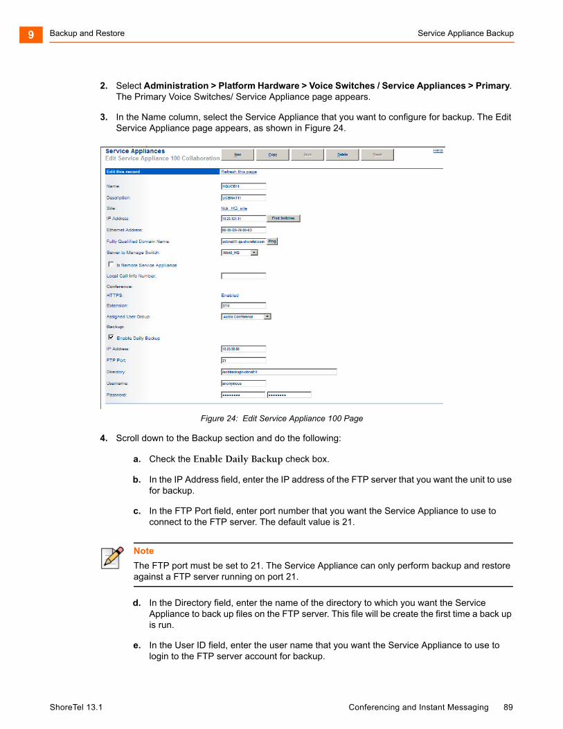
Backup and Restore Service Appliance Backup9
2. Select Administration > Platform Hardware > Voice Switches / Service Appliances > Primary. The Primary Voice Switches/ Service Appliance page appears.
3. In the Name column, select the Service Appliance that you want to configure for backup. The Edit Service Appliance page appears, as shown in Figure 24.
Figure 24: Edit Service Appliance 100 Page
4. Scroll down to the Backup section and do the following:
a. Check the Enable Daily Backup check box.
b. In the IP Address field, enter the IP address of the FTP server that you want the unit to use for backup.
c. In the FTP Port field, enter port number that you want the Service Appliance to use to connect to the FTP server. The default value is 21.
d. In the Directory field, enter the name of the directory to which you want the Service Appliance to back up files on the FTP server. This file will be create the first time a back up is run.
e. In the User ID field, enter the user name that you want the Service Appliance to use to login to the FTP server account for backup.
Note
The FTP port must be set to 21. The Service Appliance can only perform backup and restore against a FTP server running on port 21.
ShoreTel 13.1 Conferencing and Instant Messaging 89
Backup and Restore Service Appliance Restore9
f. In the Password fields, enter the password the Service Appliance needs to use to login to the FTP.
Service Appliance Restore
There is not a ShoreTel Director utility for the purpose of restoring Service Appliance content.
Restore is performed on demand through establishing an SSH or serial connection to the appliance and then using CMCA ServicesMgr command line interface (svccli) commands.
Restoring will copy the content files from the previous backup into the appliance. During restore all appliance services will be stopped.
The restore can occur on non-empty directories, but will not delete files that are in the file system but not part of the last back up. Files that are created after the previous back up remain intact. However, files that have been modified since the previous backup will be replaced by the backup version.
Files that have been deleted since the previous backup will be restored into the appliance but will not be accessible as the database links to deleted files are not maintained. If these files are required, they can be retrieved by establishing an SSH or serial connection to the appliance and retrieving them manually.
Restore procedures are considered non-routine and are not detailed in this guide. For detailed instructions, see the ShoreTel Maintenance Guide.
ShoreTel 13.1 Conferencing and Instant Messaging 90


