B-GL-317-006/PT-001 WEAPONS VOLUME 6 SHORT RANGE ANTI-ARMOUR WEAPON (MEDIUM) (BILINGUAL) WARNING ALTHOUGH NOT CLASSIFIED, THIS PUBLICATION, OR ANY PART OF IT, MAY BE EXEMPTED FROM DISCLOSURE TO THE PUBLIC UNDER THE ACCESS TO INFORMATION ACT. ALL ELEMENTS OF INFORMATION CONTAINED HEREIN MUST BE CLOSELY SCRUTINIZED TO ASCERTAIN WHETHER OR NOT THE PUBLICATION, OR ANY PART OF IT, MAY BE RELEASED. Issued on Authority of the Chief of the Defence Staff OPI: LFCHQ, Q3 Infantry 1995-09-30
Transcript
B-GL-317-006/PT-001
WEAPONS
VOLUME 6
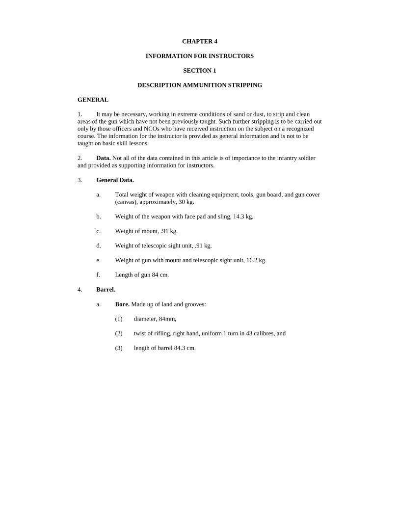
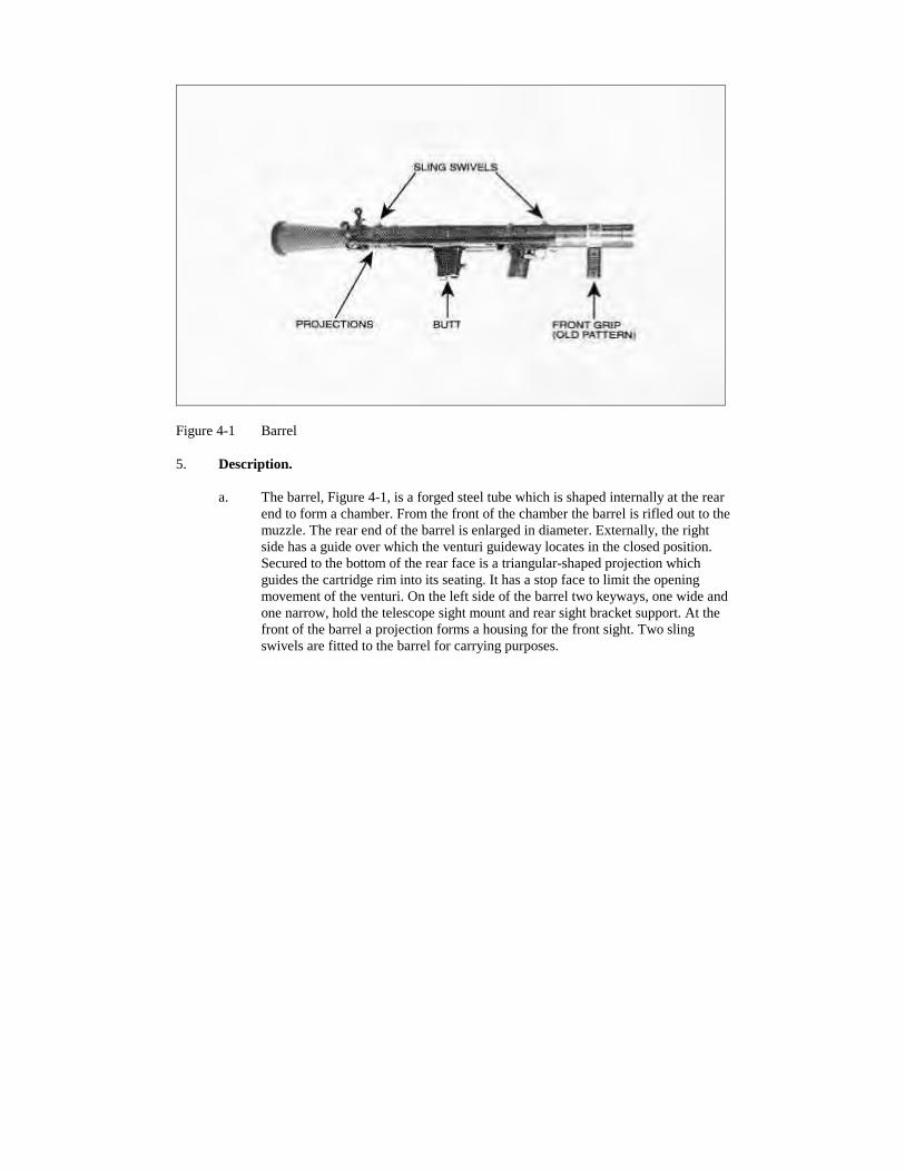
SHORT RANGEANTI-ARMOUR WEAPON(MEDIUM)
(BILINGUAL)
WARNING
ALTHOUGH NOT CLASSIFIED, THIS PUBLICATION, OR ANYPART OF IT, MAY BE EXEMPTED FROM DISCLOSURE TO THEPUBLIC UNDER THE ACCESS TO INFORMATION ACT. ALLELEMENTS OF INFORMATION CONTAINED HEREIN MUST BECLOSELY SCRUTINIZED TO ASCERTAIN WHETHER OR NOTTHE PUBLICATION, OR ANY PART OF IT, MAY BE RELEASED.
Issued on Authority of the Chief of the Defence Staff
OPI: LFCHQ, Q3 Infantry 1995-09-30
LIST OF EFFECTIVE PAGES
Insert latest changed pages; dispose of superseded pages in accordance with applicable orders.
NOTE
On a changed page, the portion of the text affected by the latest change isindicated by a vertical line in the margin of the page. Changes toillustrations are indicated by miniature pointing hands or black verticallines.
Dates of issue for original and changed pages are:
Original ..................................0..................................1995-09-30
Zero in Change No. Column indicates an original page. Total number of pages in this publicationis 162 consisting of the following:
Page No. Change No. Page No. Change No.
Title ........................................0 2-9-1 to 2-9-4 .........................0A.............................................0 2-10-1 to 2-10-6 .....................0i to xiv ....................................0 3-1 to 3-2................................01-1 to 1-4................................0 3-1-1 to 3-1-4 .........................02-1-1 to 2-1-14 .......................0 3-2-1 to 3-2-4 .........................02-2-1 to 2-2-14 .......................0 3-3-1 to 3-3-2 .........................02-3-1 to 2-3-12 .......................0 3-4-1 to 3-4-2 .........................02-4-1 to 2-4-6 .........................0 3-5-1 to 3-5-4 .........................02-5-1 to 2-5-6 .........................0 3-6-1 to 3-6-4 .........................02-6-1 to 2-6-10 .......................0 3-7-1 to 3-7-4 .........................02-7-1 to 2-7-10 .......................0 4-1 to 4-16..............................02-8-1 to 2-8-6 .........................0 5-1 to 5-12..............................0
Contact Office: LFC HQ, G3 Inf 3
1995 DND Canada
WEAPON SECURITY
THE SECURITY OF SMALL ARMS AND SMALL ARMSAMMUNITION IS YOUR RESPONSIBILITY. ENSURE YOURWEAPON(S) AND AMMUNITION ARE SECURED/PROTECTED INACCORDANCE WITH CURRENT ORDERS AND INSTRUCTIONS.
THIS PAGE IS INTENTIONALLY LEFT BLANK
WARNING
MISUSE OF WEAPONS, AMMUNITION AND EXPLOSIVES
PURPOSE
1. This order outlines Canadian Forces Policy governing the use or misuse of weapons,ammunition and explosives.
WEAPONS
2. Firing or attempting to fire locally manufactured weapons, obsolete service or foreignweapons, or weapons used for display, ceremonial or trophy purposes in museums, messes,parade grounds, armouries or such like area is prohibited except when specifically authorized byNDHQ.
3. Attention is also drawn to the following references which concern offences connectedwith the use or misuse of weapons:
a. National Defence Act, Section 117,
b. Criminal Code of Canada, Sections 82 to 106,
c. QR & O 103.59, and
d. A-SJ-100-001/AS-000, Security Orders for the Department of National Defence,Volume 1, Chapter 30.
AMMUNITION AND EXPLOSIVES
4. Tampering with or use of service and commercial ammunition or explosives for otherthan their designed purpose is prohibited.
5. Except as prescribed in paragraph 6, the modification, breakdown or sectioning of fiveammunition for experimental, instructional or any other purpose, or manufacture of explosives isforbidden; this prohibition includes:
a. unauthorized interchange of fuses or primers or both;
b. experiments with blank ammunition to alter the powder charge or to introduce anyother substance into the cartridge case or into the weapon with the approvedcartridge;
c. experiments involving the use of altered propelling charges or bursting chargeswith ammunition of any type;
d. the use of any non-service or obsolete ammunition;
e. the use of foreign ammunition other than that received through normal supplychannels or supplied in accordance with NATO Standardization Agreements;
f. the manufacture and use of locally fabricated explosive training devices, battlesimulators, saluting charges, etc;
g. an alteration to the design of ammunition or explosive devices;
h. deviations from authorized drills for use of ammunition or explosive devices; and
i. rendering live ammunition inert for the use as museum or instructional items.
6. The prohibition in paragraph 5 does not apply to:
a. authorized experiments, modifications, etc, carried out by experimental, research,proof or inspection establishments;
b. authorized breakdown, modification, repairs, proof-testing, etc, carried out asnormal functions of a Canadian Forces ammunition depot or base ammunitionfacility;
c. personnel employed at Canadian Forces School of Aerospace and OrdnanceEngineering as instructors or trainees under supervision, when breaking down iscarried out as part of a course training standard and in accordance with anapproved course training plan;
d. the use for its designed role of commercial pattern ammunition, which is obtainedby local purchase as specified in CFP 137 or as authorized by NDHQ inaccordance with CFAO 36-19;
e. the use for its designed role of commercial pattern ammunition which is taken intoservice and catalogued;
f. hand-loading small arms ammunition in accordance with CFAO 50-18; and
g. other cases, when specifically authorized by NDHQ.
FOREWORD
1. B-GL-317-006/PT-001, Short Range Anti-Armour Weapon (Medium), is issued onauthority of the Chief of the Defence Staff.
2. This publication is effective upon receipt and supersedes B-GL-317-006/PT-001 dated 14January 1974.
3. Comments and suggestions for changes should be forwarded through the normal channelsto G3 Infantry, Land Force Command Headquarters.
4. In order to avoid confusion in the weapons generic titles, the 84 mm Carl Gustav wasrenamed Short Range Anti-Armour Weapon (Medium) as a consequence of the introduction ofthe Short Range Anti-Armour Weapon (Heavy) ERYX which carries a heavier explosive chargeand has greater destructive capabilities.
THIS PAGE IS INTENTIONALLY LEFT BLANK
RECORD OF CHANGES
Identification of Change
Change No. DateDate Entered Signature
THIS PAGE IS INTENTIONALLY LEFT BLANK
CONTENTS
CHAPTER 1 - GENERAL
IntroductionAimFormatTechnical DataOrganization of InstructionPractice PeriodsClassroom OrganizationHearing ConservationAbbreviations
Lesson 2 - Firing Positions - Loading and Unloading
Instructor's NotesConduct of the Lesson
Lesson 3 - Use of Sights and Aiming at Stationary and Moving Targets
Instructor's NotesConduct of the Lesson
Lesson 4 - Basic Mechanism, Firing and Misfire Drills
Instructor's NotesConduct of the Lesson
Lesson 5 - Boresighting the Telescope and Iron Sights
Instructor's NotesConduct of the Lesson
Lesson 6 - The Sub-Calibre Training Device - FFV 553
Instructor's NotesConduct of the Lesson
Lesson 7 - Handling
Instructor's NotesConduct of the Lesson
Lesson 8 - AFV Recognition Training
Instructor's NotesConduct of the Lesson
Lesson 9 - Cartridge, 84mm, HEDP FFV502
Instructor's NotesConduct of the Lesson
Lesson 10 - Sub-Calibre Adapter - 6.5mm
Instructor's NotesConduct of the Lesson
CHAPTER 3 - PRACTICE LESSONS - INTRODUCTION
GeneralCompetitionMaster and PupilNight LessonsNBC Lessons
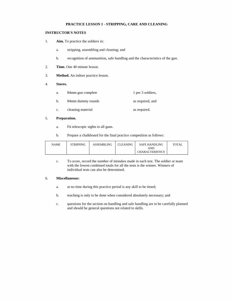
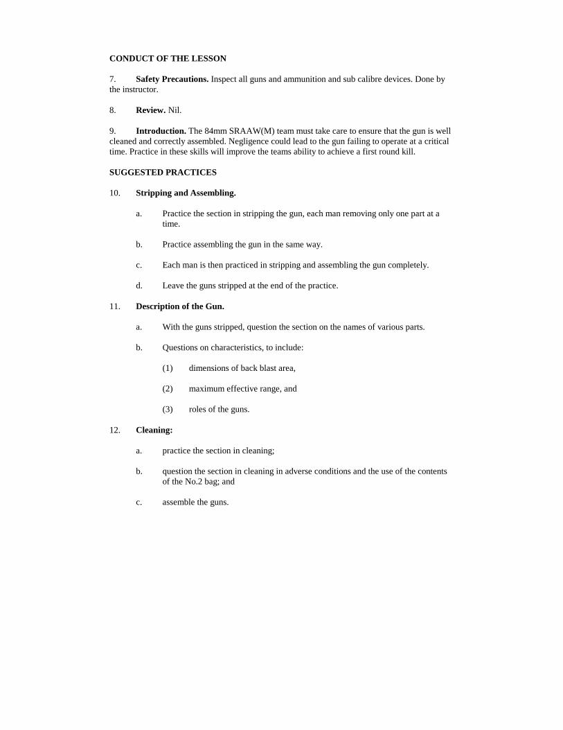
Practice Lesson 1 - Stripping, Care and Cleaning
Instructor's NotesConduct of the LessonSuggested PracticesFinal PracticeConclusion
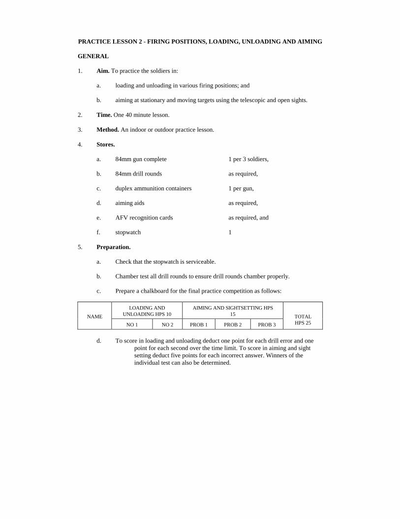
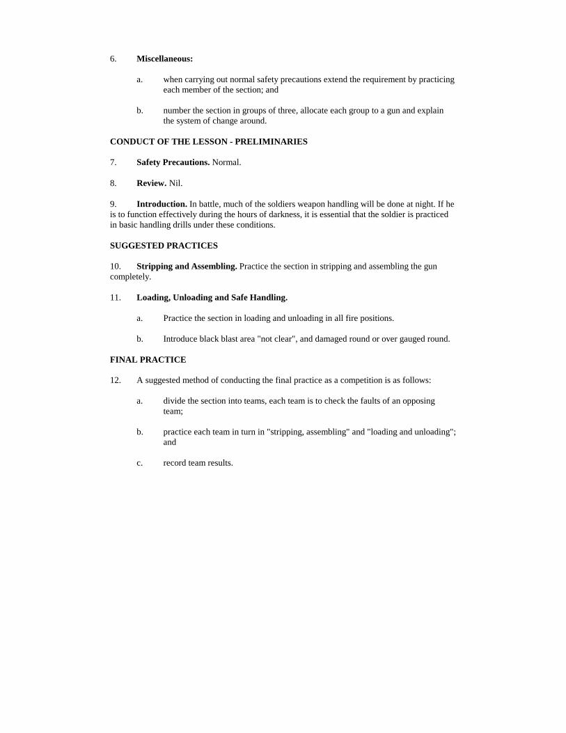
Practice Lesson 2 - Firing Positions, Loading, Unloading and Aiming
GeneralConduct of the Lesson - PreliminariesSuggested PracticesFinal PracticeConclusion
Practice Lesson 3 - Safety, Stripping, Assembling and Gun Drills at Night
Instructor's Notes - GeneralConduct of the Lesson - PreliminariesSuggested PracticesFinal PracticeConclusion
Practice Lesson 4 - Firing, Misfire Drills
Instructor's Notes - GeneralConduct of the Lesson - PreliminariesSuggested PracticesConclusion
Practice Lesson 5 - Tactical Handling at Night
Instructor's Notes - General .... :Conduct of the Lesson - PreliminariesSuggested Practice By DayDaylight Preparation For Night PracticeNight PracticeConclusion
Practice Lesson 6 - NBCD Handling
Instructor's Notes - GeneralConduct of the Lesson - PreliminariesSuggest PracticeFinal PracticeConclusion
Practice Lesson 7 - NBC Tactical Handling
Instructor's Notes - GeneralConduct of the Lesson - PreliminariesIntroductionSuggested PracticesFinal PracticeConclusion
CHAPTER 4 - INFORMATION FOR INSTRUCTORS
Section 1 - Description Ammunition, Stripping, Assembling and Cleaning
GeneralCarl Gustav M3 SystemGeneralUse of 25 Metre Ranges and Indoor TrainingGeneral
CHAPTER 5 - RANGE PRACTICES
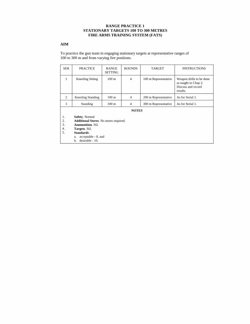
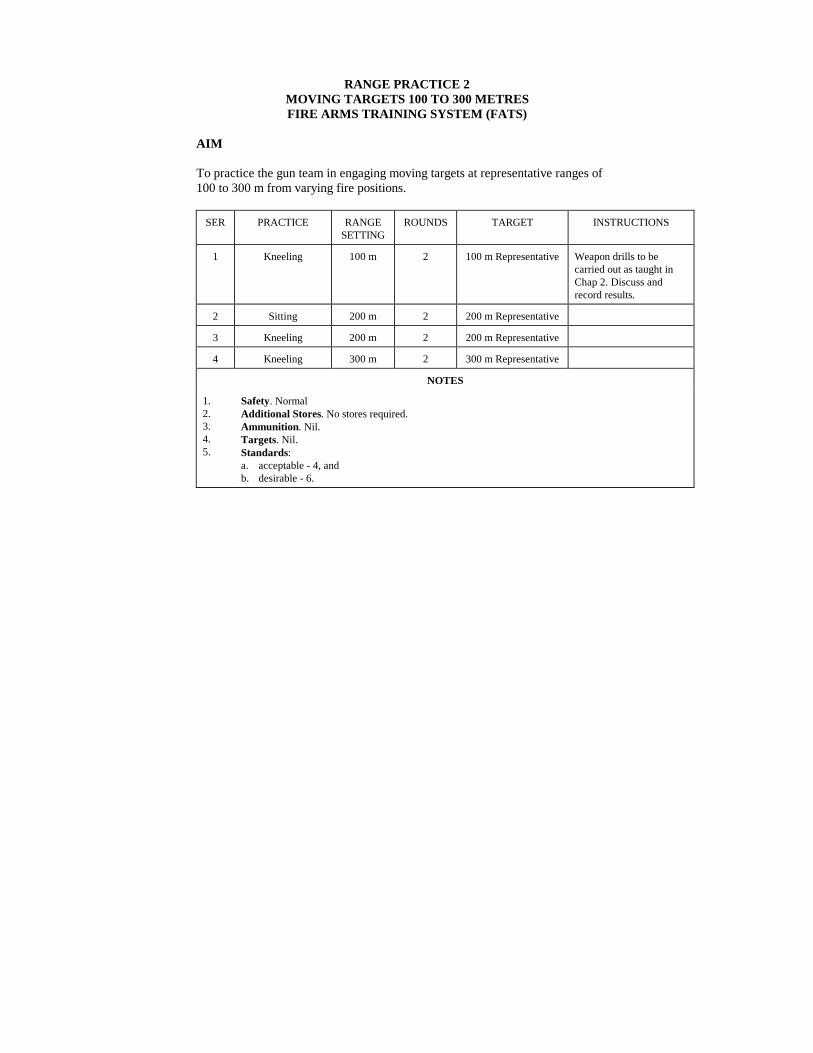
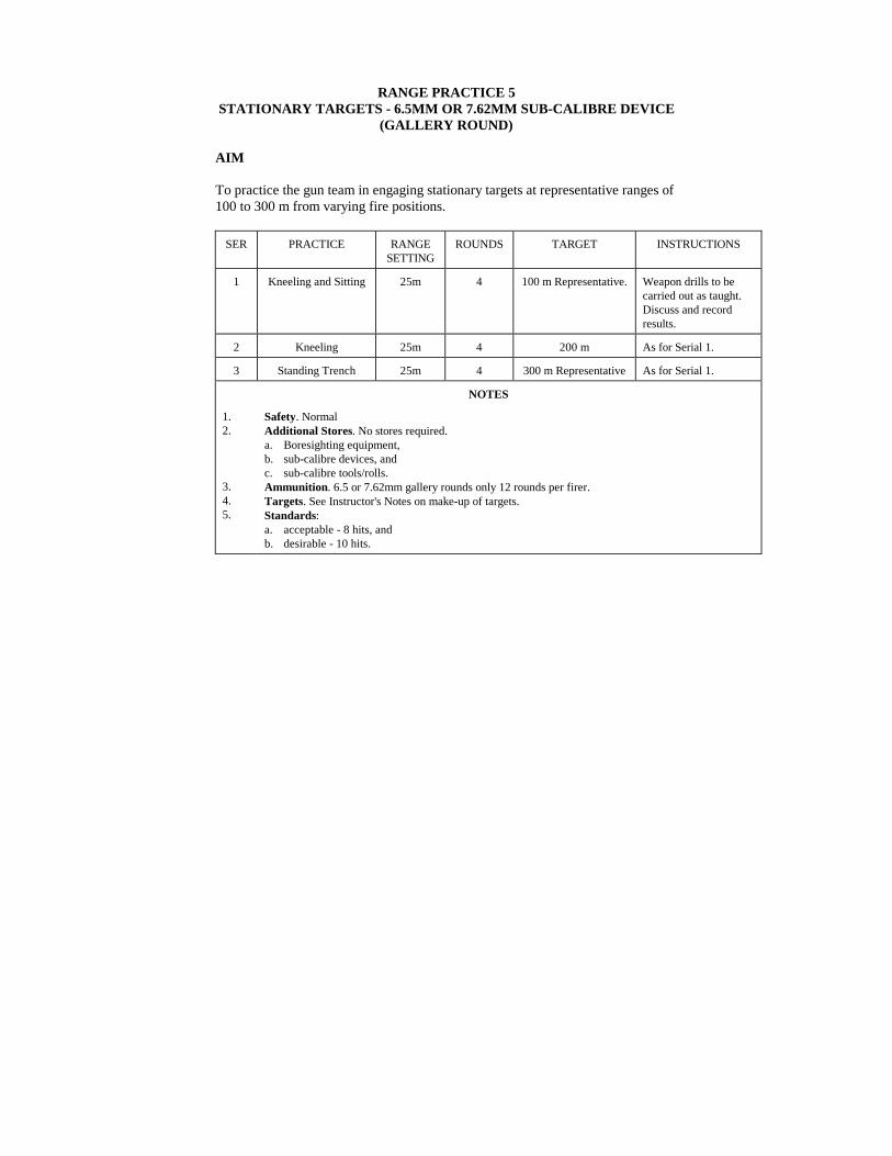
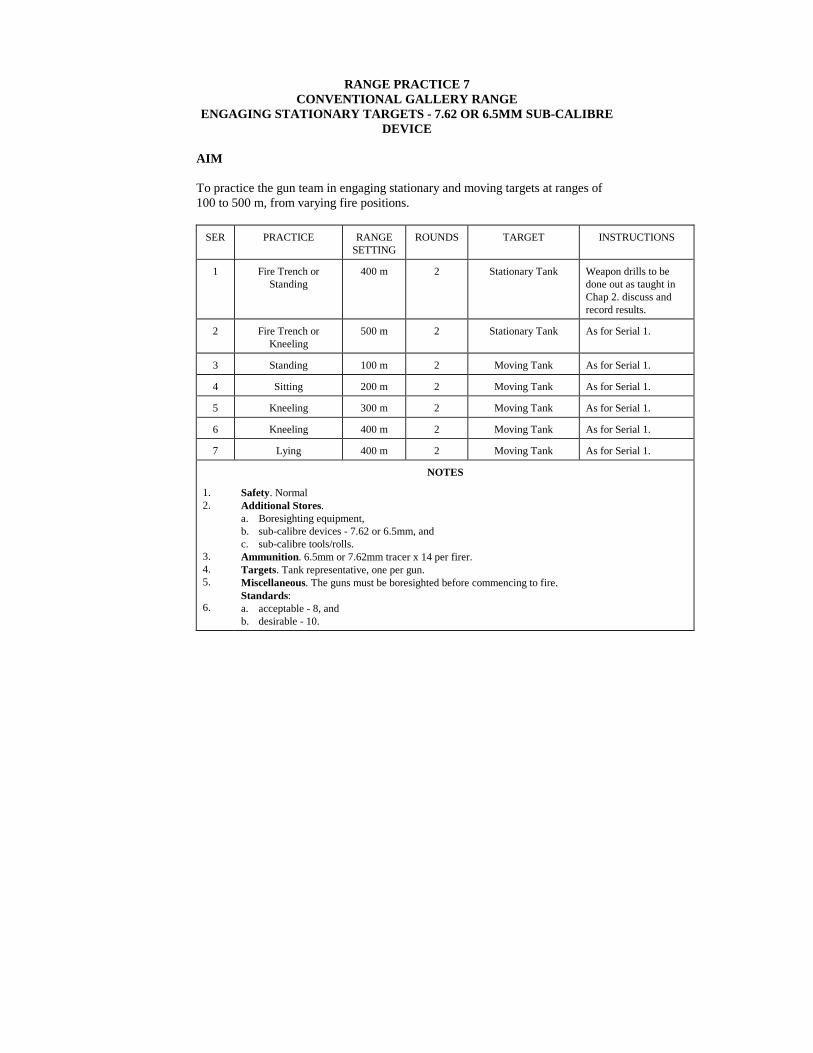
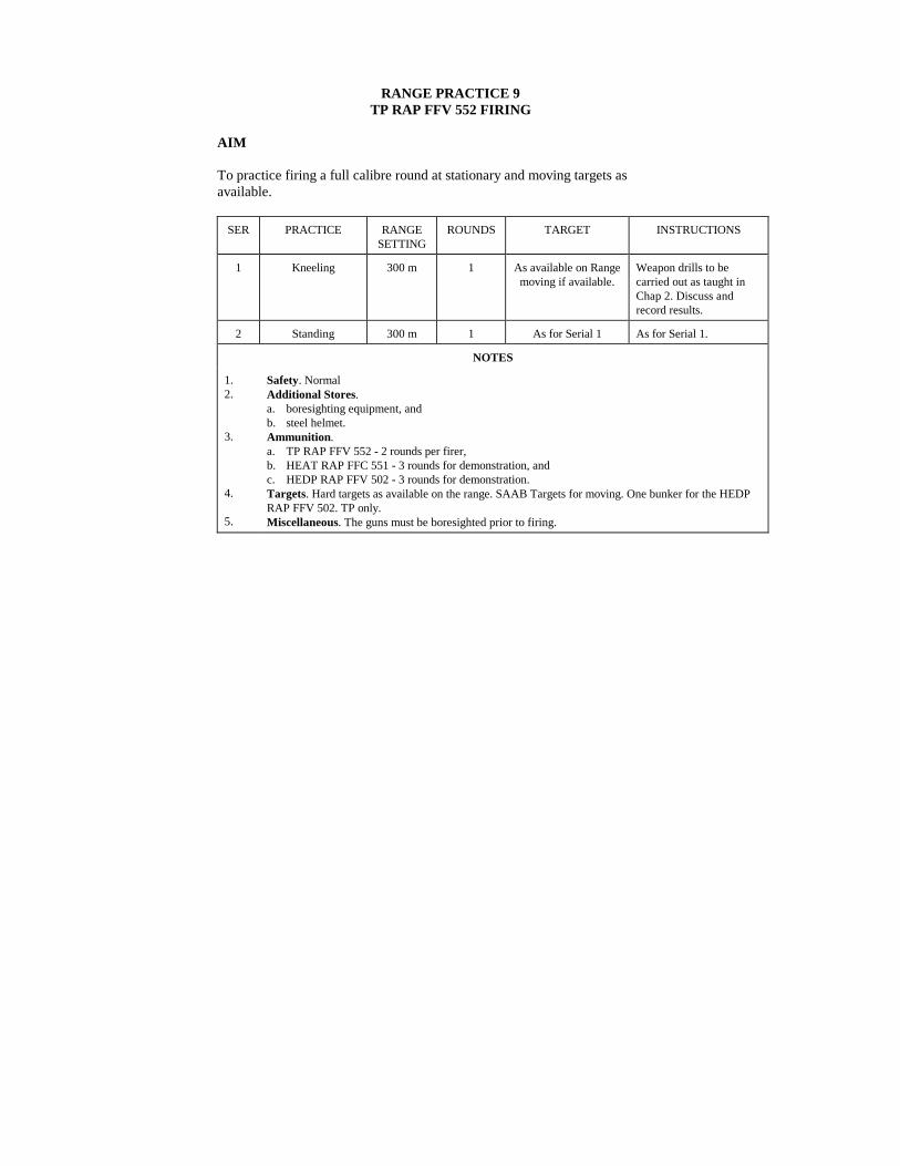
IntroductionAimGeneralRange Practice 1 - Stationary Targets 1 00 to 300 Metres Fire ArmsTraining Systems (FATS)Range Practice 2 - Moving Targets 1 00 to 300 Metres Fire ArmsTraining System (FATS)Range Practice 3 - Firing in a NBC Environment Fire Arms TrainingSystem (FATS)Range Practice 4 - 100 m Gallery Range Zeroing 7.62 or 6.5mmSub-Calibre DeviceRange Practice 5 - Stationary Targets - 6 5mm or 7.62mmSub-Calibre Device (Gallery Round)Range Practice 6 - 25 Metre Range Firing in aNBC Environment - 6.65mm or 7.62mm Sub-Calibre Device (Gallery Round)Range Practice 7 - Conventional Gallery Range Engaging StationaryTargets - 7.62 or 6.5mm Sub-Calibre DeviceRange Practice 8 - Conventional Gallery Range Engaging MovingTargets - 7.62 or 6.5mm Sub-Calibre DeviceRange Practice 9 - TP RAP FFV 552 Firing
LIST OF FIGURES
FIGURES
1-1 SRAAW(M) Front Grip (a) old pattern and (b) new pattern2-1-1 The 84mm Short Range Anti-Armour Weapon (Medium)2-1-2 Ammunition Recognition2-1-3 Cartridge Case Assembly FFV 551, w/Colour Code2-1-4 Shell 84mm HEAT RAP FFV 5512-1-5 Shell 84mm TP RAP FFV 552 (w/fins deployed) w/Colour Code2-1-6 Sight Bag Carried by No. 12-1-7 Tools and Spare Parts w/Bag Carried by No. 22-1-8 Cleaning Tools w/Bag carried by No. 32-2-1 Kneeling Position, Stationary Target2-2-2 Kneeling Position, Moving Target2-2-3 Kneeling Position, Same Side as No. 12-2-4 Loading (2 sheets)2-2-5 Sitting Position, Stationary Targets2-2-6 Sitting Position, Moving Targets2-2-7 Standing Position2-2-8 Prone Position2-3-1 MBT Vulnerable Spots2-3-2 APC Vulnerable Spots2-3-3 Reconnaissance Vehicle Vulnerable Spots2-3-4 Telescopic Sight FFV 556 w/Range Knob2-3-5 Telescopic Sight w/Graticule Pattern2-3-6 Telescopic Sight Pattern - Head On/Withdrawing Targets2-3-7 Iron Sight Pattern - Head On/Withdrawing Targets2-3-8 Leads2-4-1 Mechanism2-5-1 Boresight Fitted2-5-2 Boresight with Iron Sights2-6-1 Sub-calibre Training Device FFV 5532-6-2 Description FFV 553 w/adapter2-6-3 The 7.62mm Tracer Rd FFV 553 with Holder FFV 8402-6-4 The 7.62mm Tracer Rd FFV 553 (Being placed into the Adapter)2-6-5 Loading the FFV 840 Cap with Holder into the SCTD2-6-6 Loading and Setting the SCTD into the Gun2-7-1 Camouflaged 84mm Gun2-7-2 Slung Over the Shoulder2-7-3 Carriage Across the Body2-7-4 Side Crawl2-7-5 Leopard Crawl2-10-1 Cocking the Mechanism with Cocking Tool2-10-2 Cleaning Tools4-1 Barrel
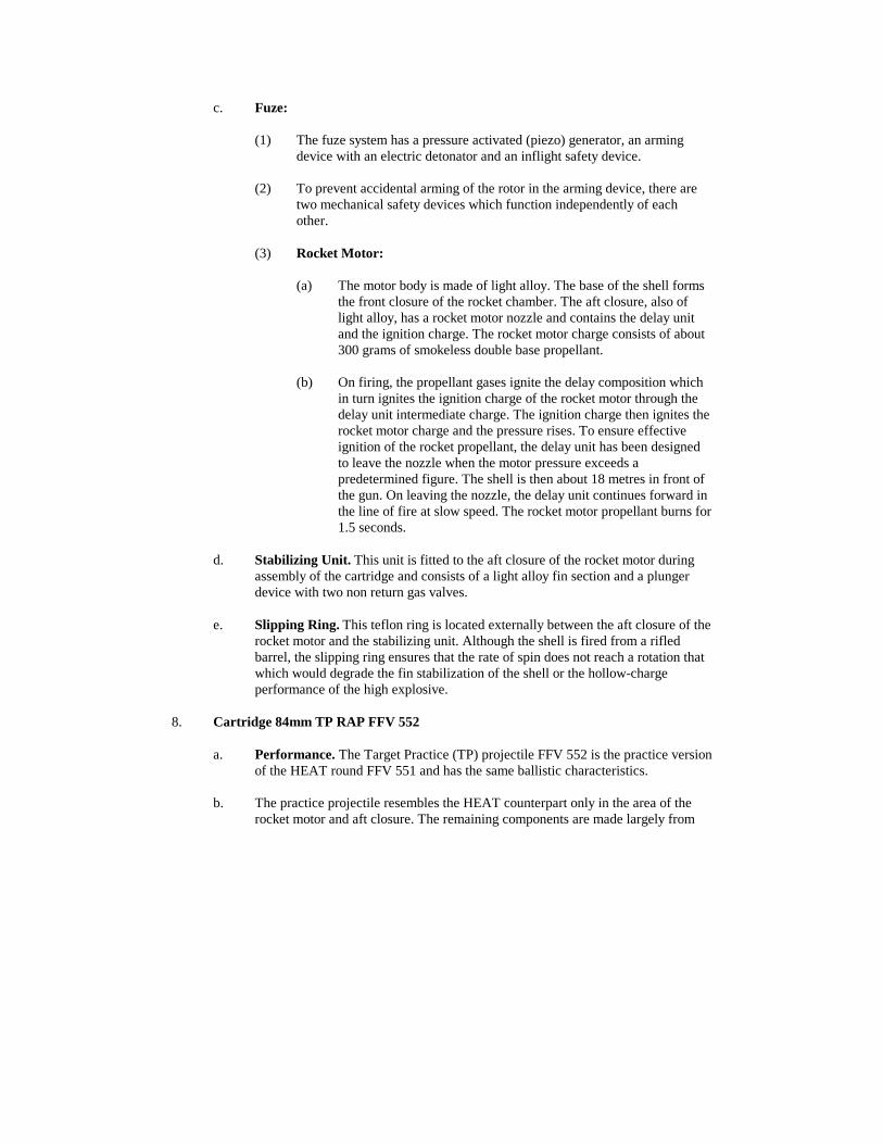
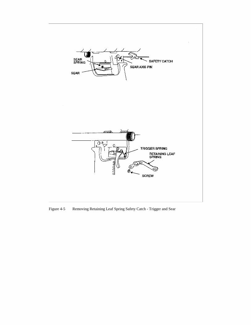
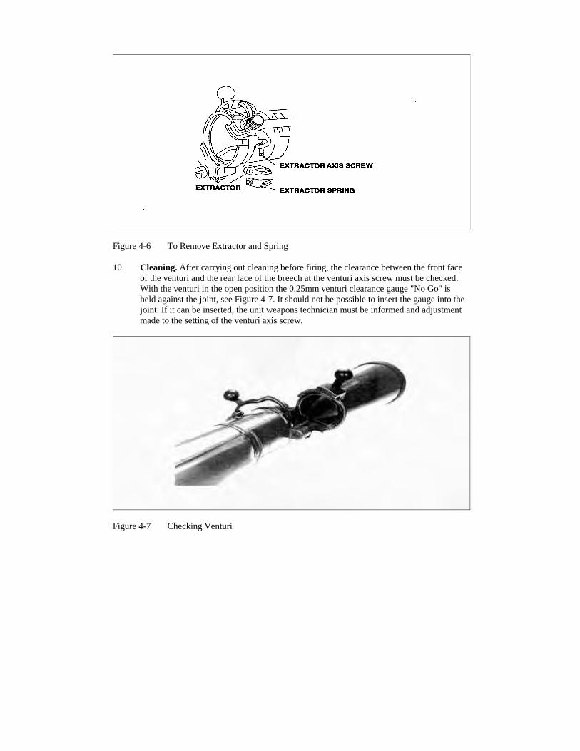
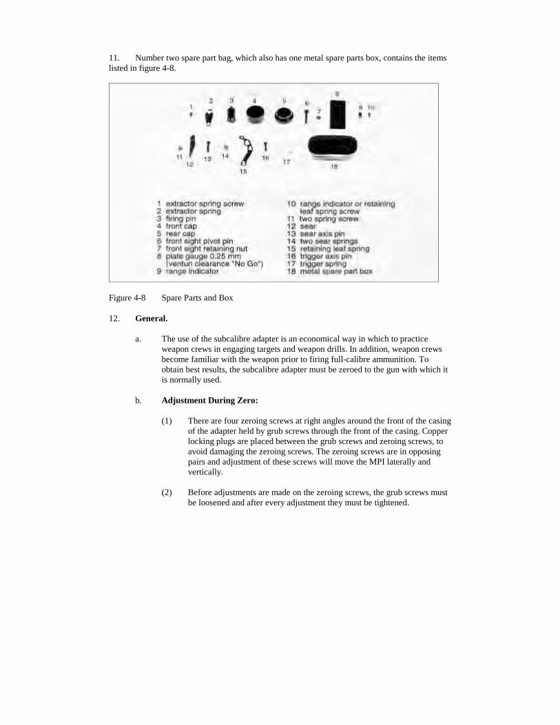
4-2 Venturi4-3 Venturi Lock4-4 Basic Stripping4-5 Removing Retaining Leaf Spring Safety Catch - Trigger and Sear4-6 To Remove Extractor and Spring4-7 Checking Venturi4-8 Spare Parts and Box4-9 6.5mm MPI Scoring Trace
THIS PAGE IS INTENTIONALLY LEFT BLANK
CHAPTER 1
GENERAL
INTRODUCTION
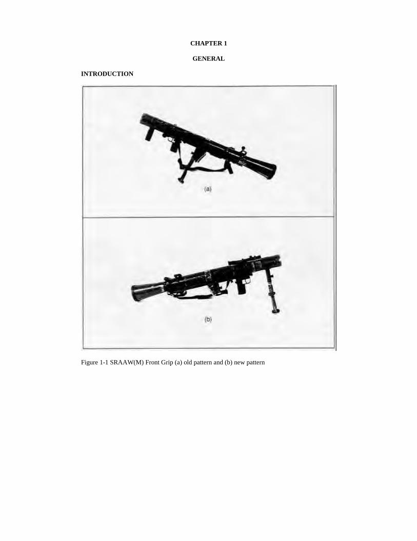
Figure 1-1 SRAAW(M) Front Grip (a) old pattern and (b) new pattern
AIM
1. This publication contains instructional material on the Short Range Anti-armour Weapon(Medium) (SRAAW(M)) for use by section commanders and small arms instructors. It enablesinstructors to teach the maintenance, handling and firing skills necessary to achieve theoperational standards required under all conditions.
FORMAT
2. The information in Chapters 2 and 3 is presented in lesson plan format. The manual islaid out as follows:
a. Chapter 1 contains general information about the 84mm SRAAW(M) andteaching methods;
b. Chapter 2 contains the basic skills and the specific information required bysoldiers to operate the SRAAW(M);
c. Chapter 3 consists of practice periods designed to further develop the skills andtechniques taught in Chapter 2;
d. Chapter 4 contains information for instructors; and
e. Chapter 5 contains range practices.
TECHNICAL DATA
3. Calibre - 84mm.
4. Weight Gun:
a. complete with mount and telescopic sight - 16.35 kg;
b. complete with cleaning equipment, tools, gun board and gun cover (canvas) - 30kg.
5. Twist of Rifling - right hand.
6. Type of Sights - telescopic and luminous (phosphorous painted iron).
7. Sight Range - 900 m.
8. System of Operation - breech loaded, percussion fired.
9. Muzzle Velocity - 310 mls for HEAT RAP FFV 551 and TP RAP FFV 552 and 230 mlsfor HEDP FFV 502.
ORGANIZATION OF INSTRUCTION
10. The lessons and practice periods are best taught and practiced in the sequence laid downin the pamphlet. Instructors are allowed latitude in the method adopted to teach individuallessons provided that they do not deviate from the information specified.
11. Practice periods can be repeated according to progress. Instructors should remember thatconstant instruction and practice without firing makes the subject dull. Every effort should bemade to introduce live firing as soon as the soldier has mastered the basic skills.
PRACTICE PERIODS
12. General. All training must be progressive and avoid unnecessary repetition. A soldierlearns skills and facts in the basic lessons which should be taught only once during his service.He then requires practice in order to quicken, improve and maintain his skills and to get the factsfirmly fixed in his mind.
13. The sequence for each stage of a practice period is:
a. remind by explanations;
b. assess weaknesses - by practice or test;
c. improve on weaknesses - by practice; and
d. progressive practice - by competitions.
14. The practice periods are intended as a guide to exercising soldiers during their training.The instructor should plan the period on an assessment of the soldiers' weak points.
15. Faults should be immediately brought to the attention of the soldiers and corrected.
16. If it becomes obvious during a practice period that the soldiers have failed to grasp aparticular skill the instructor will have to teach that part of the basic lesson again.
17. Practice periods can be repeated according to the progress of the soldiers.
18. The incentive of competition will always help to make practice more interesting. Anentire practice period can be based on competitions if the instructor so wishes. Some points onconducting competitions are:
a. Teams may be formed.
b. The instructor must ensure that the selected teams are all fairly equal in ability.The more advanced members of the team will help the weaker members.
c. Marks can be awarded up to a given total, or start with a total and deduct marksfor mistakes as the competition progresses.
d. A chart drawn on a chalkboard or a sheet of paper on which to mark results shouldalways be used.
e. Further interest can always be attained by making one team watch another to findfaults which result in the awarding or deducting marks.
f. Above all, the instructor must make certain that competitions are simple andrealistic. They must exercise the soldiers ability to perform a particular skill.
CLASSROOM ORGANIZATION
19. Prior to the start of all lessons, number the class into teams of two or three as necessary.Ideally, there should be no more than ten students per instructor. Each team and the instructorshould have a weapon.
HEARING CONSERVATION
20. The dangers resulting from non-compliance with the detailed rules for hearing protectioncannot be too strongly emphasized. Unless the rules are observed there is a significant dangerthat permanent hearing damage may occur.
ABBREVIATIONS
21. The following abbreviations are of particular importance to this manual:
a. MPI - mean point of impact,
b. m/s - metres per second,
c. FFV - Forenad Fabric Verken,
d. AFV - armoured fighting vehicle,
e. FEBA - forward edge of the battle area,
f. IA - immediate action,
g. IWS - individual weapon sight,
h. kg - kilogram,
i. SRAAW(M) - Short Range Anti-Armour Weapon (Medium),
j. MBT - main battle tank,
k. RDX - cyclonite cyclotrimomthylene trinitramine (explosive),
l. TETRYL - trinirophenyl methyl-nitramine (explosive),
m. TNT - tri-nitro-toluene (explosive),
n. HMX - homocyclonite cyclotetramethylene tetranitramine (explosive), and
1. Aim. To describe the gun and its ammunition, to teach the safety precautions and how tostrip, assemble and clean the gun.
2. Time. Three 40 minute lessons.
3. Method. A basic instructional lesson.
4. Stores.
a. 84mm gun complete per 3 soldiers,
b. 84mm display rounds: FFV 551, 552 1 per gun,
c. FFV 553 SCTD, 7.62mm T/RFFV 553 and FFV 840,
d. ammunition recognition diagram 1
e. duplex ammunition containers 1 set per gun,
f. cleaning rags as required,
g. tables 1 per gun (optional),
h. optic Sight FFV 556 1 per gun,
i. Luminous Sights 1 per gun, and
j. M3 Carl Gustav (light weight) 1 (if available).
5. Preparation. Layout the section room as follows:
a. place each weapon on a table with the telescopic sight FFV 556 and mount fitted.Place alongside:
(1) the No. 1 bag,
(2) the No. 2 bag, tool roll removed and screwdrivers laid out,
(3) muzzle and venturi covers off, and
(4) cleaning materials.
b. Select one gun for demonstration and place alongside it:
(1) duplex ammunition container and display round,
(2) ammunition recognition diagrams, and
(3) No 1 and No 2 bag laid out as for the other guns.
c. Check that all guns are serviceable.
d. Prepare a chalkboard to illustrate the backblast danger area.
6. Miscellaneous:
a. Number the section in groups of three and allocated one group per gun prior tosafety precautions.
b. Use initial order for the commencement of each practice stage, i.e., safetyprecautions - "No. 1s and 2s out and carry out safety precautions", thereafter callout "change". Explain this system of control prior to the first practice stage.
c. Ensure that as parts are stripped they are put in a clean place.
d. When handling the various parts the instructor is to name them and their purpose.However, at this stage, the soldier is not expected to memorize all the names.
e. Emphasize that stripping and assembling should be carried out with reasonablecare and never practiced against time.
f. Cleaning in adverse conditions can be taught by question and answer using priorknowledge of the personal weapon.
g. Live ammunition is not to be used under any circumstances.
CONDUCT OF THE LESSON
7. Safety Precautions. Inspect all guns, ammunition and sub-calibre devices.
8. Review. Nil.
9. Introduction. Explain that the 84mm SRAAW(M) is breech loaded and percussion fired.There is no recoil as the gas pressure, escaping rearward through the venturi, equalizes the recoilforces. The weapon is shoulder controlled and can be fired from any of the normal rifle firingpositions. It is capable of disabling or destroying any known AFV provided it is hit in avulnerable area.
10. The M3 Carl Gustav system is the principal platoon anti-armour gun because of its lightweight. It has the ability to withstand arctic, tropic and desert conditions, see Instructor Notes.
11. Characteristics. Explain and illustrate as necessary the following:
a. Accuracy. Accuracy and penetration power are its main characteristics. Thetelescopic sight (FFV 556) iron sight and night sight allows accuracy to bemaintained under moderately adverse conditions of weather and light.
b. Range. The maximum range is 700 metres. The maximum effective range againsta stationary target is 500 metres and against moving targets is 400 metres.
c. Flexibility. Although its primary role is as an anti-armour weapon, the gun can beemployed against buildings, gun emplacements and field defences.
d. Portability. The gun weighs 16.35 kg and can be carried and fired by one man,the No. 1. A No. 2 assists in the handling drills and carries ammunition.
e. Sights. Four types of sights are used with this gun:
(1) iron sights attached to the gun,
(2) telescopic sight (FFV 556) unit,
(3) luminous sights, phosphorous painted, and
(4) PVS 502.
f. Backblast. Because the gun is recoilless it produces, at the moment of firing, adistinct flash and blast rearwards. The danger area extends 30 metres rearward atan angle of 800 mils to either flank of the line of fire. This area must be clear ofany troops, equipment or obstruction at the moment of firing. When siting theweapon it must be realized that the arc of fire will determine the overall backblastarea. The gun can be fired from wooded areas as long as there are no majorobstacles in the backblast area.
g. Sub-Calibre Devices. The weapon has two sub-calibre devices, FFV 553 whichfires a 7.62mm tracer round and the FFV 480 which fires 6.5mm tracer. Refer tolessons 6 and 10.
h. Rate of Fire. The maximum rate of fire is five rounds per minute with the HEATRAP and TP RAP Round.
12. Confirm by Questions.
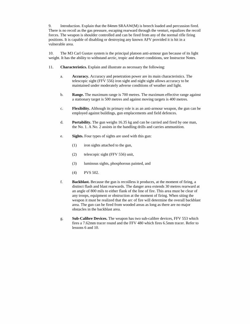
13. Description. The 84mm consists of the following major components, see Figure 2-1-1.
Figure 2-1-1 The 84mm Short Range Anti-Armour Weapon (Medium)
14. Confirm by Questions
15. Normal Safety Precautions. Explain and demonstrate. The following drills are to becarried out at the beginning and end of every lesson, exercise, operational task and when handingover or taking possession of a gun. Normal Safety Precautions are performed as follows:
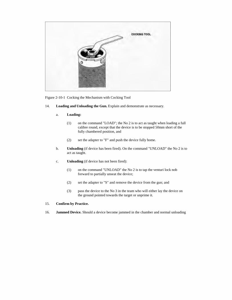
a. cock the weapon by pushing the cocking lever forward towards the pistol grip;
b. move the safety catch to "Safe";
c. push the venturi lock knob forward and raise the venturi lever thus opening thebreech;
d. visually inspect the chamber to ensure that it is clear, however, do not put yourhand in the breech due to the possibility of burning propellant;
e. visually inspect the venturi;
f. ease springs by closing the breech. To do this press down on the venturi lever andtap the venturi lock knob towards the rear to ensure that it is fully locked; and
g. move the safety catch to "Fire" and operate the trigger mechanism.
16. Confirm by Question and Practice.
17. Ammunition Recognition. The 84mm round consists of a projectile and a cased propellantcharge.
Figure 2-1-2 Ammunition Recognition
a. HEAT RAP FFV 551 (High Explosive Anti Tank Rocket Assisted Projectile).The FFV 551 round is black in colour and is marked with yellow stencilling. It isintended for use against all types of armoured fighting vehicles (AFV) includingthose fitted with protective devices such as skirting plates. The rocket motor assistenables the shell to have a flat trajectory and a short time of flight. It has anelectric fusing system. It can penetrate armour 400mm thick. The fuse becomesarmed at 5 to 15 m from the muzzle of the gun. Shown below are the majorcomponents of the ammunition.
(1) cartridge case assembly for 84mm HEAT RAP FFV 551, consists of:
Figure 2-1-3 Cartridge Case Assembly FFV 551, w/Colour Code
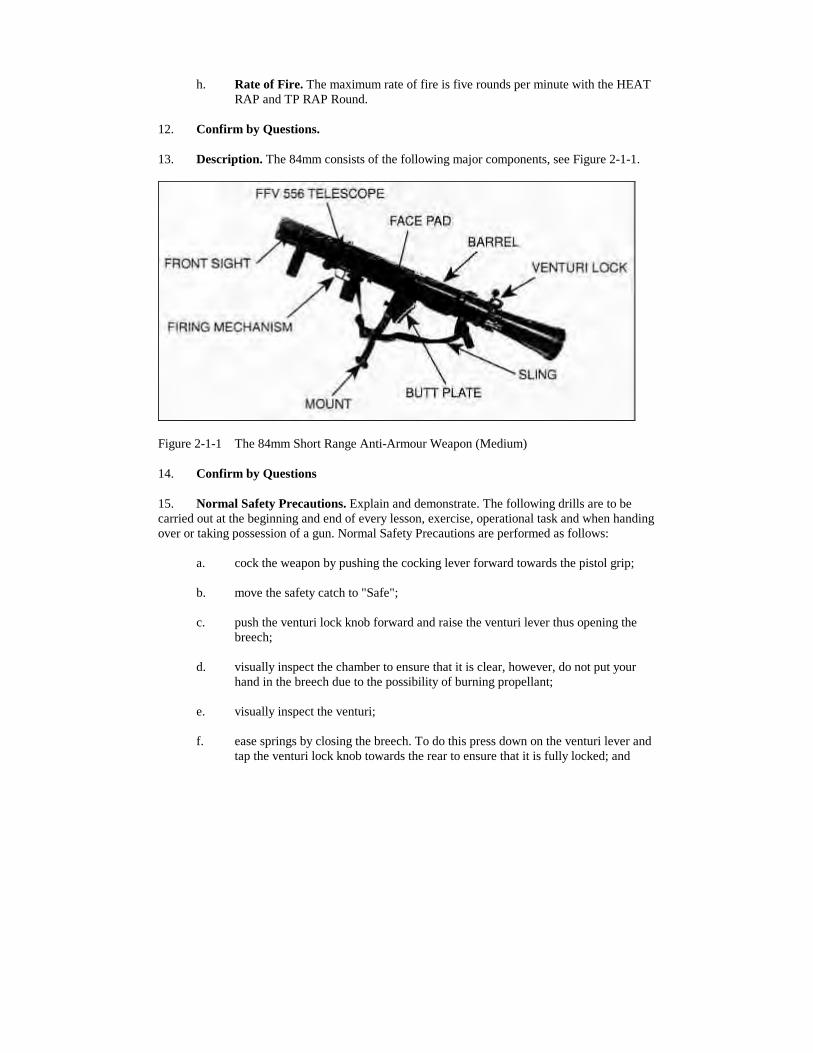
(2) the shell assembly consists of:
Figure 2-1-4 Shell 84mm HEAT RAP FFV 551
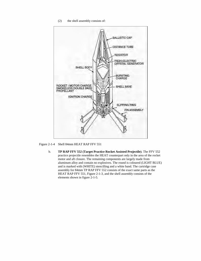
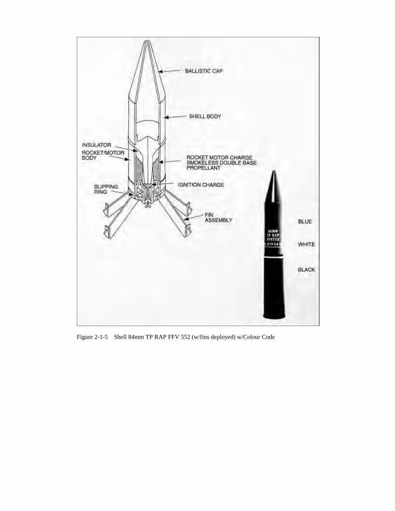
b. TP RAP FFV 552 (Target Practice Rocket Assisted Projectile). The FFV 552practice projectile resembles the HEAT counterpart only in the area of the rocketmotor and aft closure. The remaining components are largely made fromaluminum alloy and contain no explosives. The round is coloured (LIGHT BLUE)and is marked with (WHITE) stencilling and a white band. The cartridge caseassembly for 84mm TP RAP FFV 552 consists of the exact same parts as theHEAT RAP FFV 551, Figure 2-1-3, and the shell assembly consists of theelements shown in figure 2-1-5.
c. Dummy Round. The Dummy Round does not contain explosives. It is thetraining counterpart of the live round. It is an inert round used in training topractice handling and loading drills. The round is coloured (BRONZE) and ismarked with (BLACK) stencilling denoting the word "DUMMY".
d. Sub-calibre Device FFV 553. The 7.62mm T/R subcalibre adapter FFV 553 is atraining aid for firing the 84mm RCL Carl Gustav M2/M3. The loading, aiming,and firing drills with the parent weapons are the same as when firing the FFV 551ammo. The body of the FFV 553 is light grey colour, and similar in shape to theHEAT RAP Round. Detailed information on the FFV 553 is found in Lesson Sixof this chapter.
e. Sub-calibre Device - 6.5mm. The 6.5mm sub-calibre device is also used intraining to practice loading, aiming and firing. Details on the 6.5mm sub-calibredevice are found in Lesson 10 of this chapter.
f. HEDP FFV 502 (High Explosive Dual Purpose). The HEDP FFV 502, oftencalled the Bunker Buster, is a dual purpose round that can be set for"instantaneous" or on "delay". When set for "delay" the round will penetratebefore exploding. A detailed lesson is found in Lesson 9 of this chapter.
18. Confirm by Questions
19. Removing and Fitting the Telescope. Explain and demonstrate:
a. To Remove. Press down firmly on the spring plunger and rotate the sight awayfrom the gun bracket. Place the sight in the No. 1 bag; and
b. To Fit. Ensure that the iron sights are screwed fully down and folded to the gun.With the rubber guard of the telescope to the rear, fit the trunnions on the gunbracket. Holding the sight firmly, press down on the spring plunger, rotate thesight towards the gun and secure the sight to the gun bracket.
20. Additional Equipment (Figure 2-1-6): Explain
a. the No. 1 bag carried by the No. 1 contains:
(1) one telescopic sight unit,
(2) one luminous sight, with case,
(3) one lens cloth (kalarinal), and
(4) one lens brush.
Figure 2-1-6 Sight Bag Carried by No. 1
b. No. 2 bag carried by the No. 2 contains (Figure 2-1-7):
(1) one boresight front and rear,
(2) one tool and spare parts roll,
(3) two drift pins, parallel, steel,
(4) one spare firing rod spring,
(5) one spare front sight,
(6) three screwdrivers (flat point 15mm point, 9.5mm point and a reversible6mm point and 5mm point),
(7) one sight adjusting tool, and
(8) one metal spare parts box, which contains an assortment of small spareparts.
Figure 2-1-7 Tools and Spare Parts w/Bag Carried by No. 2
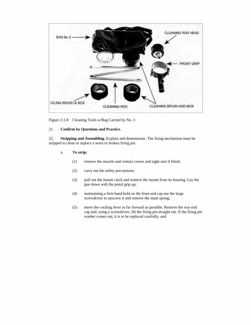
c. No. 3 bag is normally carried in the parent vehicle of the weapon's crew. Ifnecessary, the number two will carry it. It contains (Figure 2-1-8):
(1) one cleaning brush in black box,
(2) one oiling brush in clear box,
(3) one cleaning rod head,
(4) one cleaning rod, 3 sections, and
(5) one oil bottle, expendable.
Figure 2-1-8 Cleaning Tools w/Bag Carried by No. 3
21. Confirm by Questions and Practice.
22. Stripping and Assembling. Explain and demonstrate. The firing mechanism must bestripped to clean or replace a worn or broken firing pin.
a. To strip:
(1) remove the muzzle and venturi covers and sight unit if fitted;
(2) carry out the safety precautions;
(3) pull out the mount catch and remove the mount from its housing. Lay thegun down with the pistol grip up;
(4) maintaining a firm hand hold on the front end cap use the largescrewdriver to unscrew it and remove the main spring;
(5) move the cocking lever as far forward as possible. Remove the rear endcap and, using a screwdriver, lift the firing pin straight out. If the firing pinwasher comes out, it is to be replaced carefully; and
(6) for cleaning, unscrew the two retaining screws of the cocking lever andremove the lever. Swing the front mount housing to one side so that whenthe trigger is pressed the cocking rod can be withdrawn from the front ofthe firing mechanism tube.
b. To Assemble. Replace the parts in reverse order.
c. Test After Assembly. After assembly a brief test should be conducted as follows:
(1) cock gun, place safety catch to "SAFE", press trigger. The gun should notfire, and
(2) place safety catch to "FIRE" and press the trigger. The action should fire.
23. Confirm by Practice.
24. Daily Cleaning. Explain and demonstrate as follows:
a. assemble the cleaning rod and attach a lightly oiled bristle brush. Open thebreech, insert the brush from the breech end and clean the barrel. Insert cottonwaste in the eyelet of the cleaning rod, dry and inspect the barrel;
b. if fouling is present, use the dry nylon brush on the cleaning rod until all fouling isremoved;
c. similarly clean the venturi with an oily cloth, dry and inspect it;
d. leave the barrel and inside of the venturi slightly oiled;
e. clean and oil the exterior surfaces;
f. check and pack the cleaning materials;
g. under no circumstances is the telescope to be stripped. The metal parts are to bewiped clean and lightly oiled. Dust is to be removed from the lens by lightlydusting with the small brush provided, then gently polishing with the issued cloth.Check that the rubber eye guard is serviceable; and
h. for cleaning under normal conditions use the issued oil only.
25. Confirm by Practice.
26. Cleaning Before, During and After Firing. Explain and demonstrate as necessary:
a. Before Firing. Thoroughly dry out the barrel and venturi from the breech end andwipe all surplus oil from the interior;
b. During Firing. During firing clean the venturi and chamber quickly with a pad ofcotton waste or rag. This is particularly important if unburnt propellant is presentin the chamber; and
c. After Firing. Do the following:
(1) remove fouling from the breech and barrel using the dry nylon brush,
(2) clean and oil the weapon as for daily cleaning,
(3) if it is not possible to clean immediately, oil the barrel and inner surface ofthe venturi. This will loosen the fouling and assist in cleaning later,
(4) clean the firing mechanism tube using the cleaning rod and brush from the.50 calibre machine gun cleaning equipment, and
(5) pay special attention to daily cleaning for three days following firing.
27. Confirm by Questions.
28. Cleaning in Adverse Conditions. Use leading questions.
a. Hot, Sandy or Extremely Dusty Areas:
(1) all oil must be removed from the weapon to prevent the collection of sandor dirt; and
(2) care must be taken to prevent the formation of rust.
b. Arctic Conditions. All oil must be removed and moving parts lubricated withgraphite or special oil for the cold.
c. Extreme Dampness:
(1) heavy film of oil should be placed over the entire weapon; and
(2) the weapon should be closely checked for rust.
29. Confirmation by Questions.
30. Conclusion:
a. questions from the class on the entire lesson;
b. confirm by questions and practice;
c. normal safety precautions; and
d. pack kit.
31. Summary. To include the following:
a. the importance of safe handling, regular and correct maintenance. The need toidentify the different types of ammunition; and
b. a forecast of the next lesson relating to this subject.
LESSON 2 - FIRING POSITIONS - LOADING AND UNLOADING
INSTRUCTOR'S NOTES
1. Aim. To teach:
a. adjusting the mount,
b. firing positions, and
c. loading and unloading.
2. Time. Two 40 minute periods.
3. Method. A basic indoor or outdoor instructional lesson.
4. Stores:
a. 84mm complete 1 per 3 soldiers,
b. 84mm dummy rounds 2 per gun, and
c. 84mm duplex ammunition containers 1 per gun.
5. Preparation. The instructor should:
a. lay out the classroom with dummy rounds, containers and Nos. 1 and 2 bagsalongside each gun;
b. check that all dummy rounds are serviceable and chamber tested; and
c. check that the mount will fit into the front and rear housings and is adjustable.
6. Miscellaneous. The instructor should:
a. number the section in groups of three and allocated one group per gun prior tonormal safety precautions;
b. remind students that, during the practice stage, when a number is called out, thatnumber is to act as No. 1 on the gun and the next number called is to act as theNo. 2. Use the command "Change around" and explain the system of changearound;
c. during demonstrations that require a crew of two, select a student to assist;
d. do not fit telescopes during this lesson; and
e. before instructing loading drills, point out the "cartridge guide" on the gun andammunition.
CONDUCT OF THE LESSON
7. Safety Precautions. Normal.
8. Review. Question the class on ammunition recognition.
9. Introduction. Explain. To be effective in battle the gun team has to be capable ofselecting a good fire position and be able to load and unload the gun correctly.
10. Adjusting the Mount. Explain and demonstrate the following:
a. there are two housings for the mount. It may be set in the high, low or offsetposition in each housing;
b. the mount is adjusted by pulling out the catch on the housing and rotating themount; and
c. this is normally done by the No. 2.
11. Confirm by Practice. Leave the mount fitted in the rear housing.
12. Selection of Firing Position. Explain. The gun can be fired from any of the normal riflefiring positions. The selection and adoption of a steady, fire position is essential to successfulengagement with the gun. The No. 1 should consider whether:
a. the ground provides adequate cover and a clear backblast area;
b. the target can be clearly seen;
c. the target is moving; and
d. the arc of fire can be adequately covered.
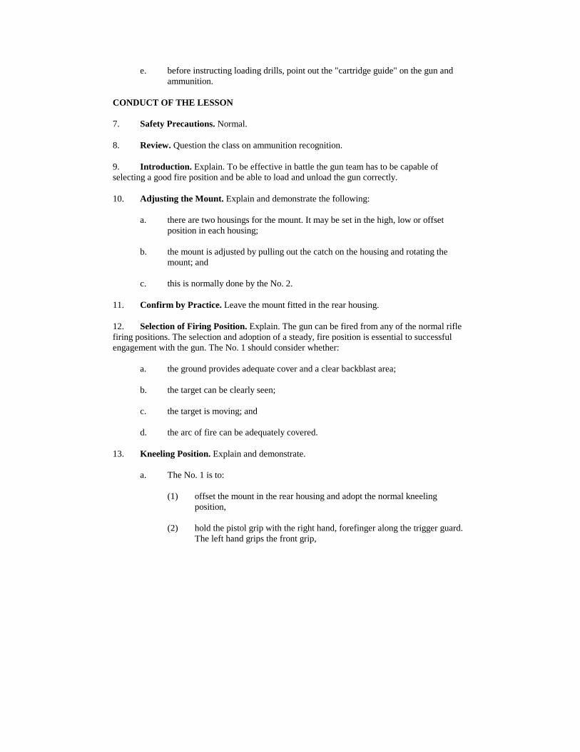
13. Kneeling Position. Explain and demonstrate.
a. The No. 1 is to:
(1) offset the mount in the rear housing and adopt the normal kneelingposition,
(2) hold the pistol grip with the right hand, forefinger along the trigger guard.The left hand grips the front grip,
(3) pull the gun firmly into the shoulder and rest the left elbow on the leftknee. The mount will then be against the chest, and
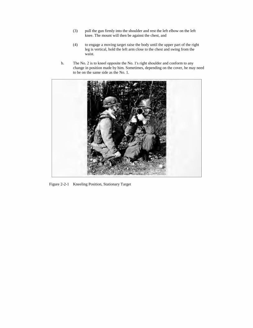
(4) to engage a moving target raise the body until the upper part of the rightleg is vertical, hold the left arm close to the chest and swing from thewaist.
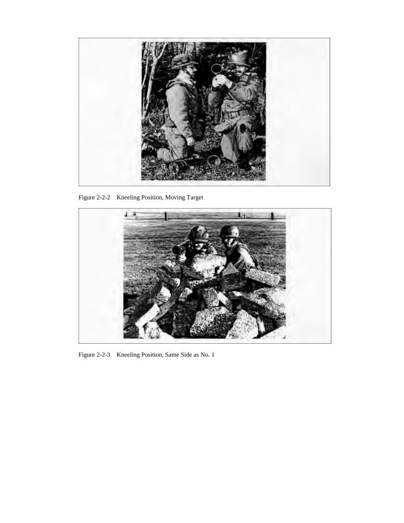
b. The No. 2 is to kneel opposite the No. 1's right shoulder and conform to anychange in position made by him. Sometimes, depending on the cover, he may needto be on the same side as the No. 1.
Figure 2-2-1 Kneeling Position, Stationary Target
Figure 2-2-2 Kneeling Position, Moving Target
Figure 2-2-3 Kneeling Position, Same Side as No. 1
14. Confirm by questions and practice.
15. Loading and Unloading. Explain and demonstrate.
a. Loading.
(1) The No. 1 on deciding to load or on receiving the order "LOAD" must:
(a) cock the gun and put the safety catch to "Safe"; and
(b) return both hands to the gun with the forefinger along the triggerguard and order "Load".
(2) When the No. 1 orders "Load" the No. 2 is to:
(a) repeat the order "Load", open the breech and remove any dirt orunburnt propellant;
(b) remove a round from its container, hold it with the nose forward;
(c) place one finger in the recess in the rim of the round and partiallyinsert the round into the chamber;
(d) ensuring that the recess and cartridge guide are aligned, push theround fully into the chamber; and
(e) close the breech, firmly tap back the venturi lock knob towards theventuri ensuring it is correctly positioned. Check that the back-blast area is clear and report "Ready". No. 1 shall repeat "Ready".
(2) The No. 2 is to frequently check the back-blast area and if it is not clear atany time when the gun is loaded he is to order "STOP". The No. 1 is torepeat "STOP", put the safety catch to "SAFE" and discontinue theengagement until the back-blast area is clear.
OPENING THE VENTURI
FEEDING THE ROUND
Figure 2-2-4 (Sheet 1 of 2) Loading
CLOSING THE VENTURI
Figure 2-2-4 (Sheet 2 of 2) Loading
b. Unloading:
(1) The No. 1 on deci(2) ding not to fire or on receiving the order "UNLOAD" is to:
(a) check that the safety catch is at "SAFE" and order "UNLOAD";and
(b) hold the gun as for loading with the muzzle pointing towards thetarget area.
(2) When the No. 1 orders "UNLOAD" the No. 2 is to:
(a) repeat the order "UNLOAD" and open the breech;
(b) tap the venturi lock knob forward, catch the round in the left handand withdraw it fully from the chamber; and
(c) close the breech, tap the venturi lock knob to the rear and report"GUN CLEAR".
(3) The No. 1, on hearing the report "GUN CLEAR", is to put the safety catchto "Fire" and operate the trigger.
(4) The No. 1 will turn the range knob to zero and/or fold the sights.
16. Confirm by practice.
17. Action with Defective Ammunition. Explain. If a round will not fit into the chamber itis to be removed and another round is to be loaded. During a lull in firing, the defective round isto be cleaned and chamber tested. If it still will not fit, it is to be marked as ‘overgauged’ andreturned.
18. Confirm by questions.
Figure 2-2-5 Sitting Position, Stationary Targets
19. The Sitting Position. Explain and demonstrate the following:
a. the No. 1 is to place the gun on the right shoulder and offset the mount in its rearhousing;
b. adopt the sitting position facing half right to the target. The right hand holds thepistol grip, forefinger slong the trigger guard. The left hand grips the front grip.
c. hold the gun firmly with the mount against the chest and pull the shoulder pad ofthe gun into the right shoulder;
d. rest both elbows forward of or inside the knees;
e. to follow a moving target keep the body erect with the elbows close into the chestand swing from the waist; and
f. the No. 2 is to kneel opposite the No. 1's right shoulder. he is to conform to anychange in position by the No. 1.
19. Confirm by practise.
Figure 2-2-6 Sitting Position, Moving Targets
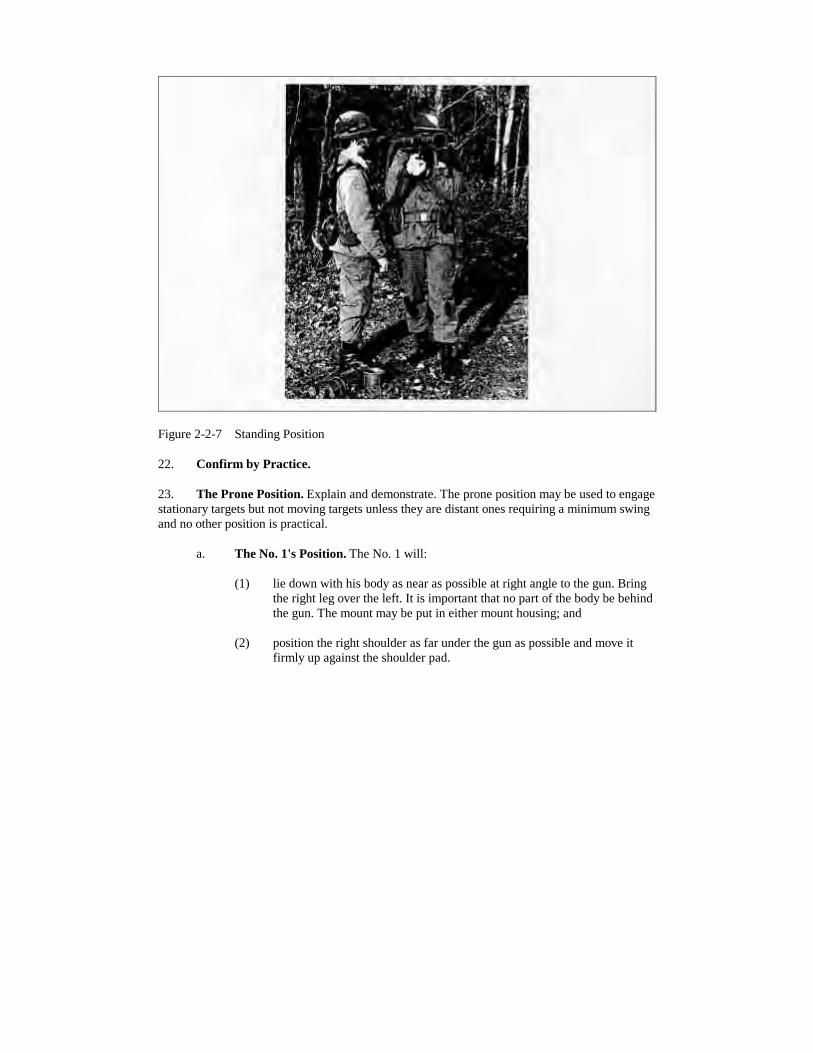
21. The Standing Position. Explain and demonstrate the following:
a. the standing position may be used when firing from high cover, a fire trench or agun emplacement;
b. stand half right to the target, body evenly balanced on both feet about half a metreapart, with the left hand holding the front grip;
c. in the open, the gun may be steadied with the left hand supporting the right handinstead of holding the front mount housing; and
d. the No. 2 is to stand close to the No. 1.
Figure 2-2-7 Standing Position
22. Confirm by Practice.
23. The Prone Position. Explain and demonstrate. The prone position may be used to engagestationary targets but not moving targets unless they are distant ones requiring a minimum swingand no other position is practical.
a. The No. 1's Position. The No. 1 will:
(1) lie down with his body as near as possible at right angle to the gun. Bringthe right leg over the left. It is important that no part of the body be behindthe gun. The mount may be put in either mount housing; and
(2) position the right shoulder as far under the gun as possible and move itfirmly up against the shoulder pad.
Figure 2-2-8 Prone Position
b. The No. 2's Position. The No. 2 will:
(1) lie opposite the No. 1 and at right angles to the gun;
(2) move close enough to the gun to operate the breech mechanism properly;and
(3) cross the left leg over the right. Check that no part of the body is behindthe venturi and that the ammunition he is carrying is not forward of themuzzle or in the backblast area.
24. Confirm by Practice.
25. Explain. Loading and unloading in other positions are the same as in the kneelingposition.
26. Final Practice. Practice loading and unloading in all positions.
27. Conclusion.
a. Questions from the section on the entire lesson.
b. Confirm by questions and practice.
c. Normal Safety Precautions.
d. Pack up.
28. Summary. To include the following:
a. factors affecting the selection of a good fire position;
b. emphasis on the need to be aware of the backblast danger area of the gun; and
c. a look forward to the next lesson relating to this subject.
LESSON 3 - USE OF SIGHTS AND AIMING AT STATIONARY AND MOVINGTARGETS
INSTRUCTOR'S NOTES
1. Aim. To teach:
a. the points of aim on various types of AFVS; and
b. how to aim at stationary and moving targets with:
(1) telescopic sight FFV 556, and
(2) iron sights.
2. Time. One 40 minute lesson.
3. Method. A basic instructional lesson.
4. Stores:
a. 84mm complete w/scopes 1 per 3 soldiers,
b. set aiming aids 1 per soldier, and
c. AFV board targets.
5. Preparation. The instructor should:
a. check the telescopes for serviceability;
b. ensure that the telescope bracket is centered;
c. open sights for serviceability;
d. position AFV representative targets on wall in front of the guns one metre abovefloor level;
e. prepare chalkboard/posters to illustrate the vulnerable areas of a Main Battle Tank(MBT), APC and recce vehicles;
f. place out a set of aiming aids for each man; and
g. draw a sight pattern for both telescopic and iron sights on the chalkboard.
6. Miscellaneous. Consider the following:
a. ideally, representative targets should be photographs of likely enemy AFV's anddepict different directions of movement;
b. number the section in groups of three and allocate one gun to each group prior tosafety precautions; and
c. Explain the change around procedure.
CONDUCT OF THE LESSON
7. Safety Precautions. Normal.
8. Review. Question the section on the characteristics of the gun, practice adoption of firepositions for moving targets.
9. Introduction. Explain. The 84mm RAP round is capable of disabling or destroying anyknown AFV. However, it is essential that the round hits a vulnerable part of the AFV in order todo so. The 84mm gun team needs to know the vulnerable areas on enemy AFVs and be able toestimate the range and speed of the vehicle, accurately and to select the correct point of aimquickly using either of the sighting systems.
10. Types of Target. Explain that an AFV target is described in the following ways:
a. Head on or Withdrawing. The whole of the front or rear is visible and little ornothing of the sides.
b. Direct Crosser. All or nearly all of either side is visible and little or none of thefront or rear.
c. Diagonal Crosser. An equal amount of the side and front or rear is visible.
11. Vulnerable Areas of AFVS. Explain using diagrams if available. There are three maingroups of AFVS:
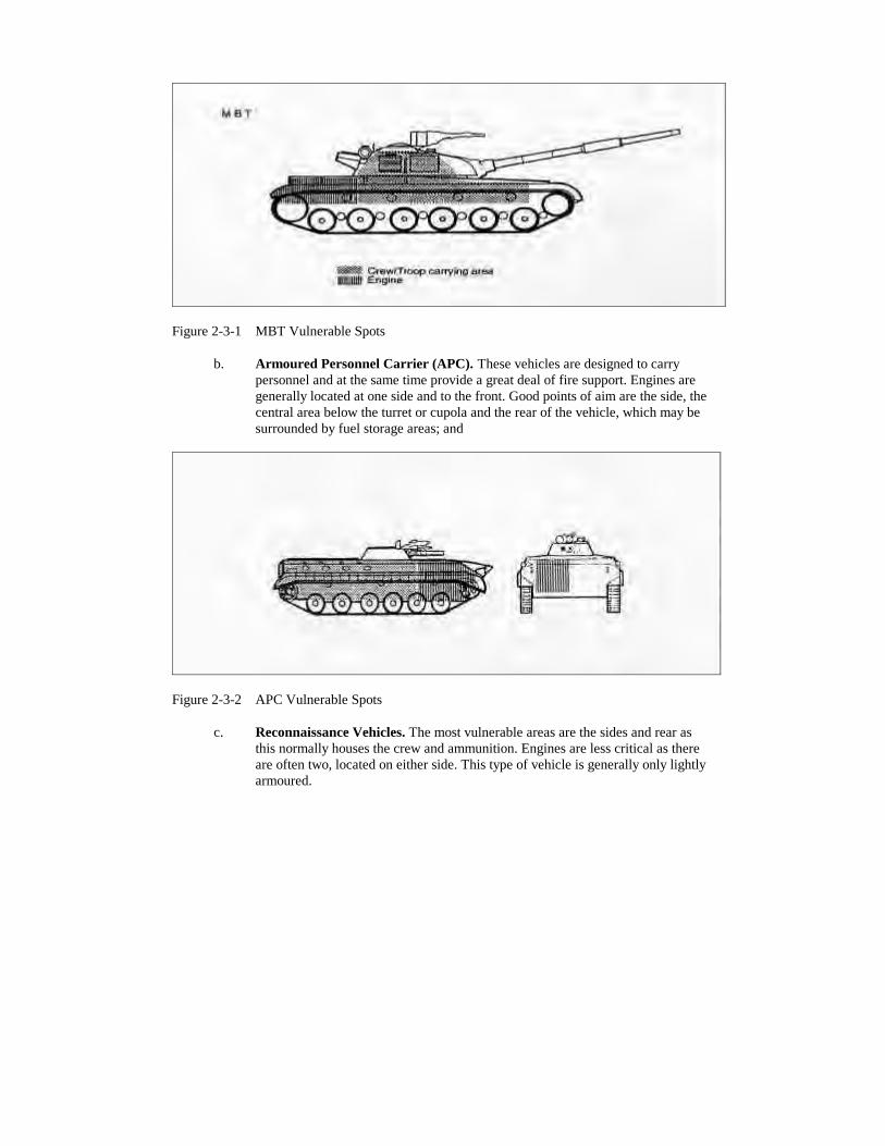
a. Main Battle Tank (MBT). MTBs are particularly vulnerable near the turret ring,the sides and rear of the hull. Ammunition is usually located within the fightingcompartment and to the sides of the driver. A frontal shot will probably notdestroy a MBT;
Figure 2-3-1 MBT Vulnerable Spots
b. Armoured Personnel Carrier (APC). These vehicles are designed to carrypersonnel and at the same time provide a great deal of fire support. Engines aregenerally located at one side and to the front. Good points of aim are the side, thecentral area below the turret or cupola and the rear of the vehicle, which may besurrounded by fuel storage areas; and
Figure 2-3-2 APC Vulnerable Spots
c. Reconnaissance Vehicles. The most vulnerable areas are the sides and rear asthis normally houses the crew and ammunition. Engines are less critical as thereare often two, located on either side. This type of vehicle is generally only lightlyarmoured.
12. Should a target be indistinct, the centre of the visible mass should be selected as the pointof aim. The gun, aerials and spare fuel tanks should be disregarded when determining the visiblemass.
13. Firing down onto the top or towards the underside of an AFV, particularly in the area ofthe fighting compartment, should destroy the vehicle.
14. Confirm by Questions.
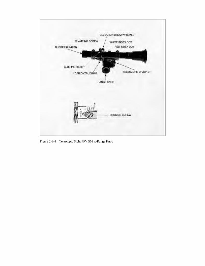
15. The Telescopic Sight. Explain and demonstrate using diagram as necessary, see Figures2-3-4 and 2-3-5.
a. the 84mm M2/M7 telescopic sight FFV 556 is the primary sighting system of thegun. It has a storage bag and the field of view is 213 mils;
b. on the left of the bracket is a range knob with two sets of figures:
(1) White Figures. The left or outer figures range from zero (0) to ninehundred (900) metres marked every hundred. Above the 200 m mark thereis also a mark every 50 m. These figures are used for the HE RAP FFV552, TP RAP FFV 552 and the sub-calibre;
(2) Light Green Figures. The right or inner figures range from zero (0) tothirteen hundred (1300) metres, marked every hundred, in divisions offifty metres. These figures are used for NATO country HE and SMOKEammunition; and
c. two parallel grooves around the circumference of the knob have a number ofdimples in which a spring loaded detent plunger can engage to lock the knob atthe required range;
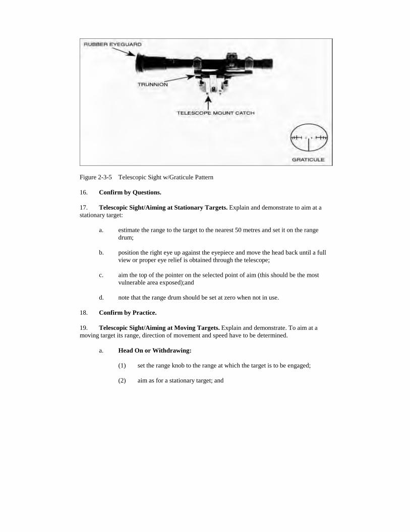
d. the sight pattern consists of a vertical pointer, the tip of which is used to aim atstationary, head on or withdrawing targets. On either side of the pointer are leadmarks; lead one a small square, lead two a short vertical line; lead three betweentwo long vertical lines and lead four the far long vertical line. The inverted smallline is used for aiming at vehicles moving faster than 50 kph. Leads will vary fordiagonal crossings. The horizontal lines are used to assist in maintaining elevationwhen aiming;
e. on the top and on the left of the telescope there is an elevation and horizontaldrum scale respectively. These allow the telescopic sight pattern to be adjustedduring boresighting and zeroing. They are locked into position by locking screws;and
f. after adjustment of the drums, the scale is read against index lines which arecolour coded as described:
(1) WHITE DOT. It is used to zero the scale when boresighting at alltemperatures and is the drum zero index at all temperatures from -10ΕC to30ΕC;
(2) RED DOT. It is used as the drum zero index at temperatures above 30ΕC;and
(3) BLUEDOT. It is used as the drum zero index at ammunition temperaturesbelow -10ΕC.
17. Telescopic Sight/Aiming at Stationary Targets. Explain and demonstrate to aim at astationary target:
a. estimate the range to the target to the nearest 50 metres and set it on the rangedrum;
b. position the right eye up against the eyepiece and move the head back until a fullview or proper eye relief is obtained through the telescope;
c. aim the top of the pointer on the selected point of aim (this should be the mostvulnerable area exposed);and
d. note that the range drum should be set at zero when not in use.
18. Confirm by Practice.
19. Telescopic Sight/Aiming at Moving Targets. Explain and demonstrate. To aim at amoving target its range, direction of movement and speed have to be determined.
a. Head On or Withdrawing:
(1) set the range knob to the range at which the target is to be engaged;
(2) aim as for a stationary target; and
(3) the target is engaged when the aim is correct and the target is at theselected range (Figure 2-3-6).
Figure 2-3-6 Telescopic Sight Pattern - Head On/Withdrawing Targets
Figure 2-3-7 Iron Sight Pattern - Head On/Withdrawing Targets
b. Direct and Diagonal Crossing:
(1) set the range knob to the range at which the target is to be engaged; and
(2) ensure correct lead is taken, see Figure 2-3-8.
20. Method of Engagement. The No. 1 is to decide whether to aim and swing with thetarget, or to aim in front of the target and allow it to move on to the lead. Care must be taken toestablish the correct elevation when employing the latter method.
21. Confirm by Practice.
22. Iron Sights. Explain and demonstrate:
a. the iron sights are used when the telescope is unavailable;
b. the backsight is hinged to the gun and consists of an aperture, range scale andrange indicator. The aperture and the range scale indicator are adjustable forboresighting purposes; and
c. the foresight is also hinged to the gun and consists of a vertical pointer and twosmall horizontal bars.
23. Care of the Sight. To minimize the chances of damage to the iron sights during carriagethe back sight is to be screwed down fully and both sights folded into the side of the gun afteruse.
24. Aiming. With Open Sights explain and demonstrate:
a. Stationary Targets. Estimate the range, set the sights, select the point of aim andfocus the foresight within the aperture as for the rifle; and
b. Moving Targets. Additionally estimate the speed of the target and decide on themethod of engagement. Lead is applied as for Figure 2-3-8.
Figure 2-3-8 Leads
25. Confirm by Practice.
26. Corrections. Explain as a result of the observation of strike, corrections are made asfollows:
a. Elevation. Quickly add or drop the setting on the range scale and engage. For atarget between range settings i.e., a range of 275 m, set the drum at the nexthighest setting - in this case 300 metres, and aim slightly lower on the target; and
b. Wind. Strong crosswinds must be considered when firing, particularly at longerranges. As a guide, in a strong wind at a range of approximately 300 metres, aimat the upwind side of the turret or cupola as opposed to the centre of the visiblemass.
27. Conclusion.
a. Questions from the section on the entire lesson.
b. Confirm by question and practice.
c. Safety precautions.
28. Summary
a. the importance of AFV recognition and knowledge of the vulnerable areas;
b. the need to practice judging distance; and
c. a forecast of the section's next lesson in this subject.
THIS PAGE IS INTENTIONALLY LEFT BLANK
LESSON 4 - BASIC MECHANISM, FIRING AND MISFIRE DRILLS
INSTRUCTOR'S NOTES
1. Aim. To teach:
a. the action of the firing mechanism; and
b. how to fire the gun and the action on misfire.
2. Time. Two 40 minute lessons.
3. Method. A basic instructional lesson.
4. Stores:
a. 84mm complete 1 per 3 soldiers,
b. 84mm dummy rounds 2 per gun,
c. 84mm mechanism board 1 per class,
d. 84mm duplex ammunition container 1 set per gun,
e. armour representative targets 1 per gun,
f. mechanism diagram 1 per gun,
5. Preparation. The instructor should:
a. lay out the section room;
b. fit the telescope to each gun;
c. position representative targets on the wall in front of the guns and one metreabove floor level;
d. chamber test each dummy round; and
e. check that all front and rear end caps are removable.
6. Miscellaneous. Consider the following:
a. number the section in groups of three and allocate each group to a gun prior tosafety precaution;
b. explain that during the practice stage when a number is called out, that man is toact as No. 1 on the gun and the second number called is to act as No. 2. Use thecommand "Change Around" and explain the system of rotation; and
c. during the practice stage of misfire and further action drills use the commands"WEAPON FAILS TO FIRE, MISFIRE, PRIMER STRUCK, PRIMER NOTSTRUCK, 60 SECONDS ARE UP".
CONDUCT OF THE LESSON
7. Safety Precautions. Normal.
8. Review. Loading and unloading.
9. Introduction. Explain that in battle the gun numbers must work as a team to load quicklyand fire accurately. Any misfire must be dealt with quickly in order to prevent armour breakingthrough the defended position. A high standard of training in these skills is required of the team.A knowledge of the firing mechanism will assist the team in determining the cause of the misfireand its remedy.
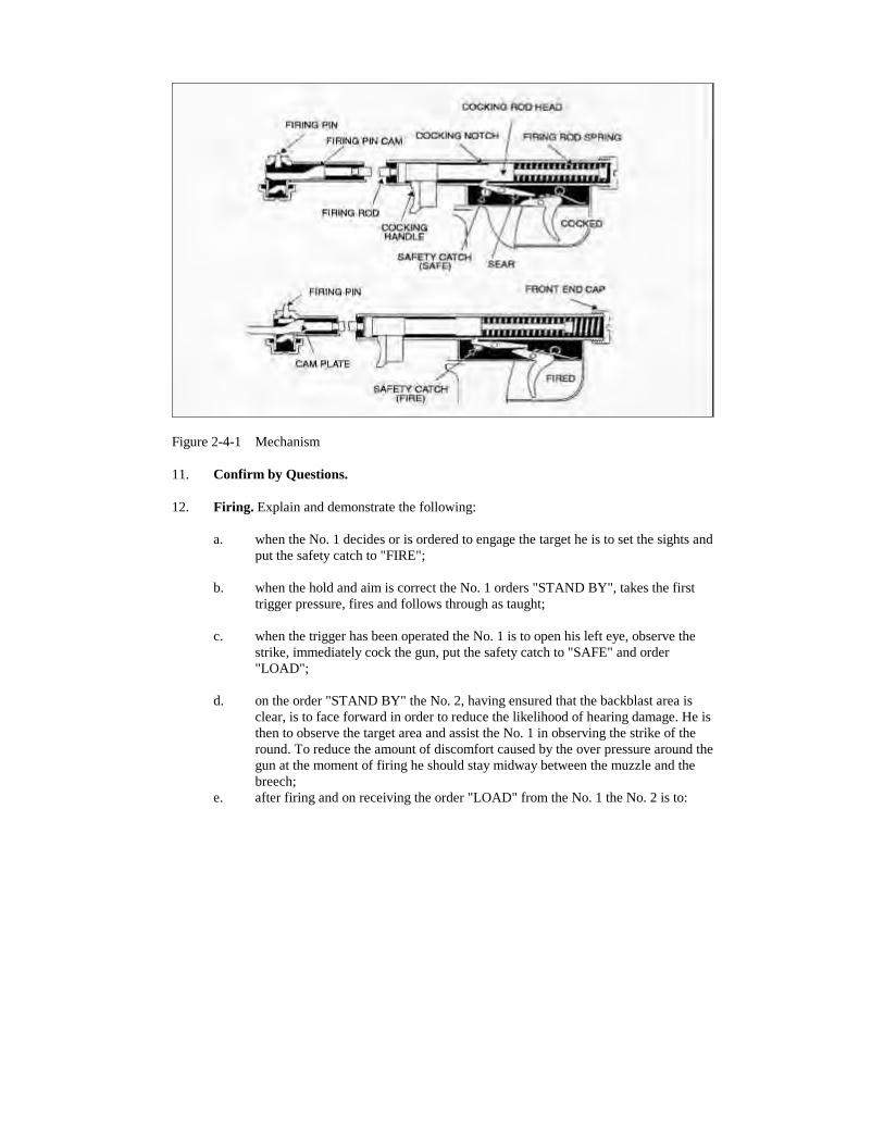
10. Basic Firing Mechanism.
a. When the gun is cocked the firing rod spring is compressed against the front endcap. The cocking rod notch on the cocking rod head engages with the hook on thesear.
b. When the trigger is pressed the sear is disengaged and the spring drives the firingrod to the rear.
c. The firing pin cam bears against the inner part of the firing pin, which is forcedinwards on to the primer cap of the round.
d. The safety catch can only be applied when the cocking rod is forward in thecocked position.
Figure 2-4-1 Mechanism
11. Confirm by Questions.
12. Firing. Explain and demonstrate the following:
a. when the No. 1 decides or is ordered to engage the target he is to set the sights andput the safety catch to "FIRE";
b. when the hold and aim is correct the No. 1 orders "STAND BY", takes the firsttrigger pressure, fires and follows through as taught;
c. when the trigger has been operated the No. 1 is to open his left eye, observe thestrike, immediately cock the gun, put the safety catch to "SAFE" and order"LOAD";
d. on the order "STAND BY" the No. 2, having ensured that the backblast area isclear, is to face forward in order to reduce the likelihood of hearing damage. He isthen to observe the target area and assist the No. 1 in observing the strike of theround. To reduce the amount of discomfort caused by the over pressure around thegun at the moment of firing he should stay midway between the muzzle and thebreech;
e. after firing and on receiving the order "LOAD" from the No. 1 the No. 2 is to:
(1) repeat the order "LOAD" and open the breech;
(2) remove the empty case and throw it off to a flank well clear of thebackblast area; and
(3) examine the chamber for unburnt propellant, remove it if necessary andload again as taught.
f. before firing again, the No. 1 is to make any corrections to range, lead or point ofaim depending on the observation of strike of the previous round; and
g. should the backblast area not be clear at any time tile No. 2 is to call out "STOP".
13. Confirm by Practice.
14. Hangfire and Misfire. Explain that:
a. a hangfire is an abnormal time lag between the trigger being operated and theround being fired. As the delay is caused by slow burning propellant, the roundcould fire without warning and therefore the gun is to be kept pointed at the targetwhile the correct drill is carried out; and
b. a misfire is caused by either a faulty firing mechanism or a faulty round.
15. Misfire Drills. Explain and demonstrate where necessary.
a. If the weapon fails to fire, the following actions shall be taken:
(1) No. 1 maintains his point of aim, recocks the weapon, puts the safety catchto "SAFE" and orders No. 2 to "CHECK VENTURI";
(2) No. 2 taps the venturi lock knob to the rear and reports to the No. 1"VENTURI LOCK CHECKED"; and
(3) No. 1 places the safety catch to "FIRE" aims and carries out the properfiring drills.
b. If the weapon fails to fire a second time, the following action shall be taken:
(1) No. 1 will report "MISFIRE" and the No. 2 repeats "MISFIRE";
(2) Nos. 1 and 2 wait one minute with the No. 1 maintaining the aim in theevent of a possible hangfire;
(3) if the gun has not fired after one minute, No. 1 recocks the weapon, placesthe safety catch to "SAFE" and orders "MISFIRE UNLOAD". No. 2
repeats "MISFIRE UNLOAD"; and
(4) after unloading the gun one of the following drills shall be carried out:
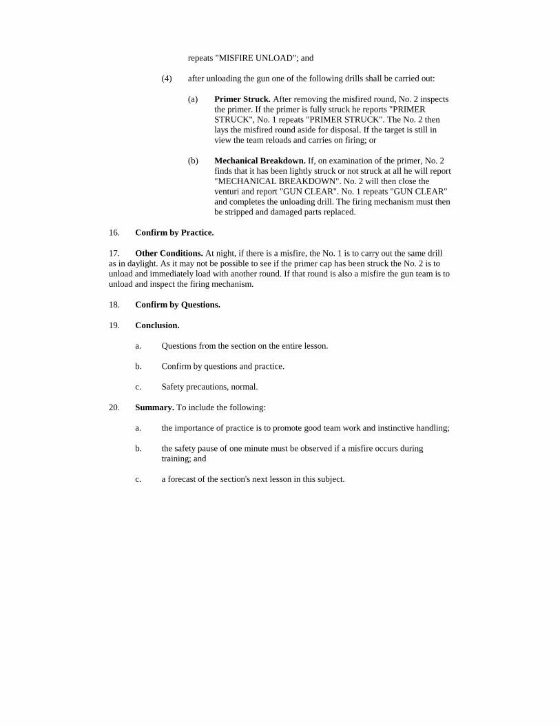
(a) Primer Struck. After removing the misfired round, No. 2 inspectsthe primer. If the primer is fully struck he reports "PRIMERSTRUCK", No. 1 repeats "PRIMER STRUCK". The No. 2 thenlays the misfired round aside for disposal. If the target is still inview the team reloads and carries on firing; or
(b) Mechanical Breakdown. If, on examination of the primer, No. 2finds that it has been lightly struck or not struck at all he will report"MECHANICAL BREAKDOWN". No. 2 will then close theventuri and report "GUN CLEAR". No. 1 repeats "GUN CLEAR"and completes the unloading drill. The firing mechanism must thenbe stripped and damaged parts replaced.
16. Confirm by Practice.
17. Other Conditions. At night, if there is a misfire, the No. 1 is to carry out the same drillas in daylight. As it may not be possible to see if the primer cap has been struck the No. 2 is tounload and immediately load with another round. If that round is also a misfire the gun team is tounload and inspect the firing mechanism.
18. Confirm by Questions.
19. Conclusion.
a. Questions from the section on the entire lesson.
b. Confirm by questions and practice.
c. Safety precautions, normal.
20. Summary. To include the following:
a. the importance of practice is to promote good team work and instinctive handling;
b. the safety pause of one minute must be observed if a misfire occurs duringtraining; and
c. a forecast of the section's next lesson in this subject.
THIS PAGE IS INTENTIONALLY LEFT BLANK
LESSON 5 - BORESIGHTING THE TELESCOPE AND IRON SIGHTS
INSTRUCTOR'S NOTES
1. Aim.
a. to teach how to boresight the weapon; and
b. to teach resetting the elevation and deflection scales of the telescopic and ironsights.
2. Time. One 40 minute lesson.
3. Method. A basic outdoor instructional lesson.
4. Stores.
a. 84mm complete 1 per 3 soldiers,
b. aim diagram of the boresight 2,
c. boresighting stand 1 per gun, if available,
5. Preparation.
a. Prepare a boresight aim diagram.
b. Select an aiming target at least 400 metres away.
c. Layout the equipment, telescopic sights are not to be fitted. Unpack theboresights, small screwdrivers and combination tools.
d. Ensure that both sights are offset from their true boresight settings.
6. Miscellaneous.
a. If a fire trench is available the weapon can be steadied during boresighting by theNo. 1 using sandbags to steady the mount. The No. 2 is to lie behind the weapon,elbows rested and both hands steadying the venturi.
b. If there are no fire trenches available the prone position is to be used.
c. If available, an extra telescopic sight for the instructor is a useful aid.
d. Due to the rifling, the front boresight can be levelled by pulling out the ironforesight and checking it against the horizontal bars.
e. The ideal situation is to have the det comd act as the No. 3 to adjust the telescopicsight.
CONDUCT OF THE LESSON
7. Safety Precautions. Normal.
8. Review. Telescopic sight.
9. Introduction. The aim of boresighting is to ensure that, with the range drum set at zero,the axis of the bore and the line of sight meet at a common distance. That aiming point must be atleast 400 metres away.
10. Confirmation of boresighting is achieved by live firing either HEAT RAP or TP RAPammunition.
11. The boresighting procedure should be carried out with both the telescopic and iron sights:
a. prior to all live firing; and
b. whenever the accuracy of the weapon is in doubt.
12. Live firing is the method used to confirm the alignment of the line of sight with the axisof the barrel and the actual ranges being set on the sight.
13. Fitting the Boresights. Explain and demonstrate:
a. Rear Boresight. This has a small aperture and is shaped like the base of theround, including a recess for the cartridge guide. It is fitted by opening theventuri, inserting the boresight with the thumb and finger, and closing the venturi.
b. Front Boresight. This is inserted into the muzzle so that the straight edges of theForesight are horizontal and uppermost.
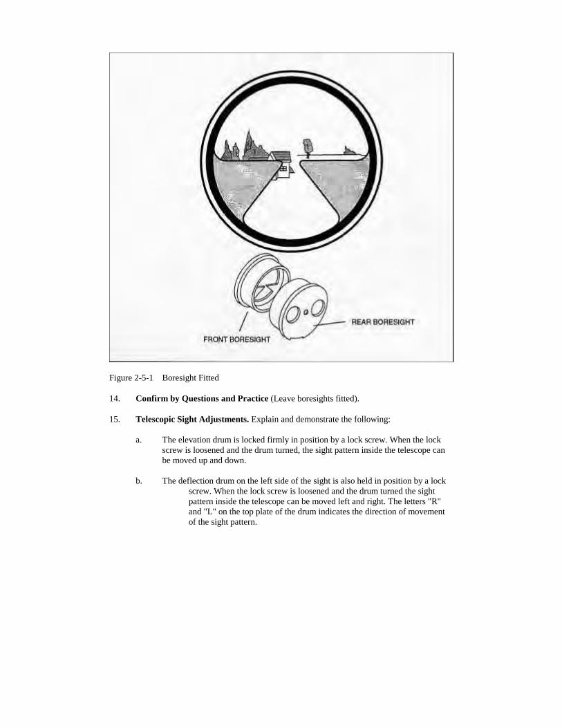
Figure 2-5-1 Boresight Fitted
14. Confirm by Questions and Practice (Leave boresights fitted).
15. Telescopic Sight Adjustments. Explain and demonstrate the following:
a. The elevation drum is locked firmly in position by a lock screw. When the lockscrew is loosened and the drum turned, the sight pattern inside the telescope canbe moved up and down.
b. The deflection drum on the left side of the sight is also held in position by a lockscrew. When the lock screw is loosened and the drum turned the sightpattern inside the telescope can be moved left and right. The letters "R"and "L" on the top plate of the drum indicates the direction of movementof the sight pattern.
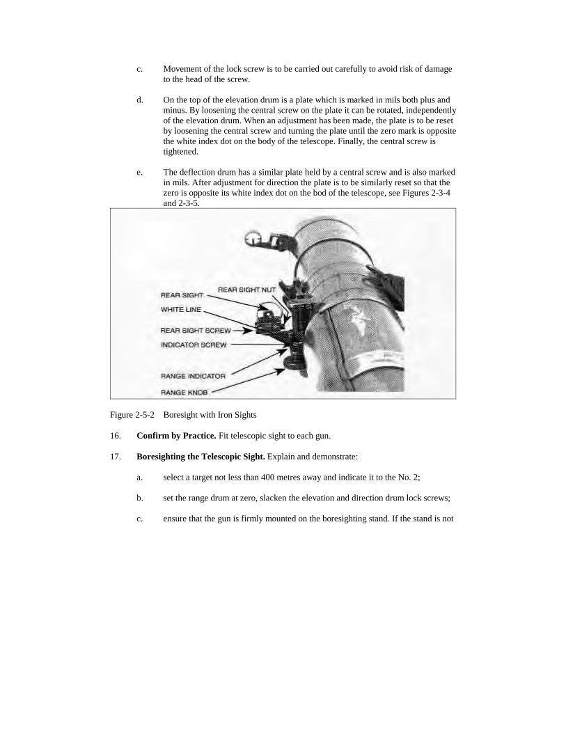
c. Movement of the lock screw is to be carried out carefully to avoid risk of damageto the head of the screw.
d. On the top of the elevation drum is a plate which is marked in mils both plus andminus. By loosening the central screw on the plate it can be rotated, independentlyof the elevation drum. When an adjustment has been made, the plate is to be resetby loosening the central screw and turning the plate until the zero mark is oppositethe white index dot on the body of the telescope. Finally, the central screw istightened.
e. The deflection drum has a similar plate held by a central screw and is also markedin mils. After adjustment for direction the plate is to be similarly reset so that thezero is opposite its white index dot on the bod of the telescope, see Figures 2-3-4and 2-3-5.
Figure 2-5-2 Boresight with Iron Sights
16. Confirm by Practice. Fit telescopic sight to each gun.
17. Boresighting the Telescopic Sight. Explain and demonstrate:
a. select a target not less than 400 metres away and indicate it to the No. 2;
b. set the range drum at zero, slacken the elevation and direction drum lock screws;
c. ensure that the gun is firmly mounted on the boresighting stand. If the stand is not
available, both No. 1 and No. 2 adopt the prone position, with No. 2 lying directlyin the rear of the gun looking through the bore;
d. the No. 2 is to aim the boresights at the target and report "ON" when a correct aimis laid;
e. if the tip of the pointer in the telescope is not pointing at the target the No. 1 willloosen the lock screws and rotate the elevation and deflection drums as taughtuntil the aim pictures through the boresight and telescope coincide;
f. the team then changes places and agree to the accuracy of the boresighting;
g. tighten both lock screws, relay the bore and check that the telescope is still on.Reset both the elevation and deflection plates to zero;
h. the axis of the bore now coincides with the line of sight through the telescope withzero range applied; and
i. if at any stage the cross check by the No. 1 and No. 2 shows an error, then thebore must be relaid and the procedure carried out again.
18. Confirm by Practice. Ensure that the telescopic sight is correctly boresighted at the endof the practice stage. (Remove telescopic sights at end of practice.)
19. The Iron Sights. Explain and demonstrate.
a. Point out the adjustment nut and screw on the back.
b. To correct an elevation error during boresighting, turn the range drum as for sightsetting. To reset the scale loosen the screw on the range indicator and position thecentre of the white line at zero on the Range Scale. Tighten the screw.
c. Errors in direction are corrected by moving the backsight aperture laterally. If theaim is to the left, loosen the screw on the left of the sight block and tighten thenut, so moving the aperture to the left. If the error is to the right, the nut must firstbe loosened and the screw tightened.
d. The scale on the backsight block is marked in mils plus and minus from a centralpoint. After final adjustment of the backsight the reading is to be noted.
20. Boresighting the Iron Sights. Explain and demonstrate (Use the same target used by theNo. 1 and No. 2 before):
a. set the range to zero;
b. lay the bore onto the target and report "ON";
c. adjust the open sights onto the target;
d. confirm by changing around;
e. reset the range scale indicator;
f. note the backsight scale reading; and
g. if the cross check by the No. 1 and the No. 2 shows an error, then the boresightingprocedure must be carried out again.
21. Confirm by Practice.
22. Conclusion.
a. Questions from the section on the entire lesson.
b. Confirm by question and practice.
c. Safety precaution, normal.
d. Pack up.
23. Summary. To include the following:
a. importance of having an aiming target not less than 400 metres away;
b. care in using the elevation and deflection drum lock screws; and
c. a forecast of the sections next lesson in this subject.
LESSON 6 - THE SUB-CALIBRE TRAINING DEVICE - FFV 553
INSTRUCTOR'S NOTES
1. Aim. To teach the characteristics of the FFV 553, S/C, 7.62mm T/R FFV 553 to include:
a. introduction;
b. description;
c. ammunition;
d. priming the device;
e. load/Fire/Unload;
f. misfire drill; and
g. care and Cleaning.
2. Time. Two 40 minute lessons.
3. Method. A basic instructional lesson.
4. Stores:
a. 84mm complete 1 per 3 soldiers,
b. FFV 553 S/C 1 per 3 soldiers,
c. 7.62mm TIR FFV 553 (DUMMY) 3 per gun,
d. FFV 840 (DUMMY) 3 per gun,
e. 7.62mm (DUMMY) if required, and
f. FFV 551 (DUMMY) 1 per gun,
5. Preparation. As follows:
a. ensure that all guns are serviceable; and
b. check that the subcalibre devices are serviceable.
6. Miscellaneous.
a. Number the section in groups of three and allocate one group per gun prior tosafety precautions.
b. Remind students that, during the practice stage, when a number is called out, thatnumber is to act as No. 1 on the gun and the next number is to act as No. 2. Usethe command "CHANGE AROUND" and explain the system of change around.
c. It must be kept in mind that the absence of backblast tends to induce carelessnessand loose holding. These points must be checked at all times.
d. Until a 7.62mm T/R FFV 553 (DUMMY) and FFV 840 cap/holder is produced,the action of loading is only to be done with a normal 7.62mm DUMMY round.
e. Functioning of the subcalibre device is found in the Instructor's Notes of Lesson 4in this chapter.
CONDUCT OF THE LESSON
7. Safety Precautions. Normal.
8. Review. Load, unload and misfire drills.
9. Introduction. Explain.
a. The 7.62mm subcalibre device FFV 553 is a training device used in conjunctionwith the 84mm SRAAW(M).
b. The device weighs 3.3 kg and is externally similar in shape to the 84mm HEAT rdFFV 551.
c. The loading, aiming and firing operation with the 84mm is the same as whenfiring the FFV 551 ammo.
d. The adapter mechanism is set to F (fire) when the device is fully inserted in thenun chamber.
e. The SCTD can be zeroed to the gun.
f. The ammo 7.62mm tracer rd FFV 553 is intended for use when firing at ranges upto 700 m. The device is fired by the shock wave from a cap.
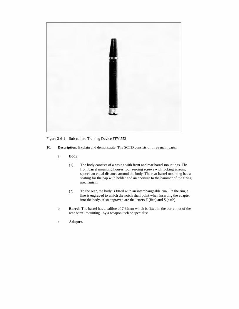
Figure 2-6-1 Sub-calibre Training Device FFV 553
10. Description. Explain and demonstrate. The SCTD consists of three main parts:
a. Body.
(1) The body consists of a casing with front and rear barrel mountings. Thefront barrel mounting houses four zeroing screws with locking screws,spaced an equal distance around the body. The rear barrel mounting has aseating for the cap with holder and an aperture to the hammer of the firingmechanism.
(2) To the rear, the body is fitted with an interchangeable rim. On the rim, aline is engraved to which the notch shall point when inserting the adapterinto the body. Also engraved are the letters F (fire) and S (safe).
b. Barrel. The barrel has a calibre of 7.62mm which is fitted in the barrel nut of therear barrel mounting by a weapon tech or specialist.
c. Adapter.
(1) The adapter has a seat for the 7.62mm round, hammer, firing pin withfiring pin spring, firing pin catch and bolt catch.
(2) The firing pin catch prevents the firing pin from striking until the adapterhas been set to F (fire).
(3) The adapter is retained in the position S and F by the engagement of thebolt catch with the grooves in the left locking shoulder of the barrel nut.
Figure 2-6-2 Description FFV 553 w/adapter
11. Confirm by Questions.
12. Ammunition. Explain and demonstrate.
a. The 7.62mm tracer round FFV 553 only is used. The nose of the bullet is white,half the rear surface of the cartridge case is black.
b. When making the subcalibre adapter ready for firing, the cap with holder FFV 840is inserted into its seating.
NOTE
Do not try to fire normal 7.62mm tracer, Ball Ammunition in thesubcalibre training device.
13. Confirm by Questions.
Figure 2-6-3 The 7.62mm Tracer Rd FFV 553 with Holder FFV 840
14. Priming the Device. Explain and demonstrate.
a. Turn the adapter counter-clockwise until the notch on the adapter points to theline on the rim and remove the adapter from the sub-calibre device.
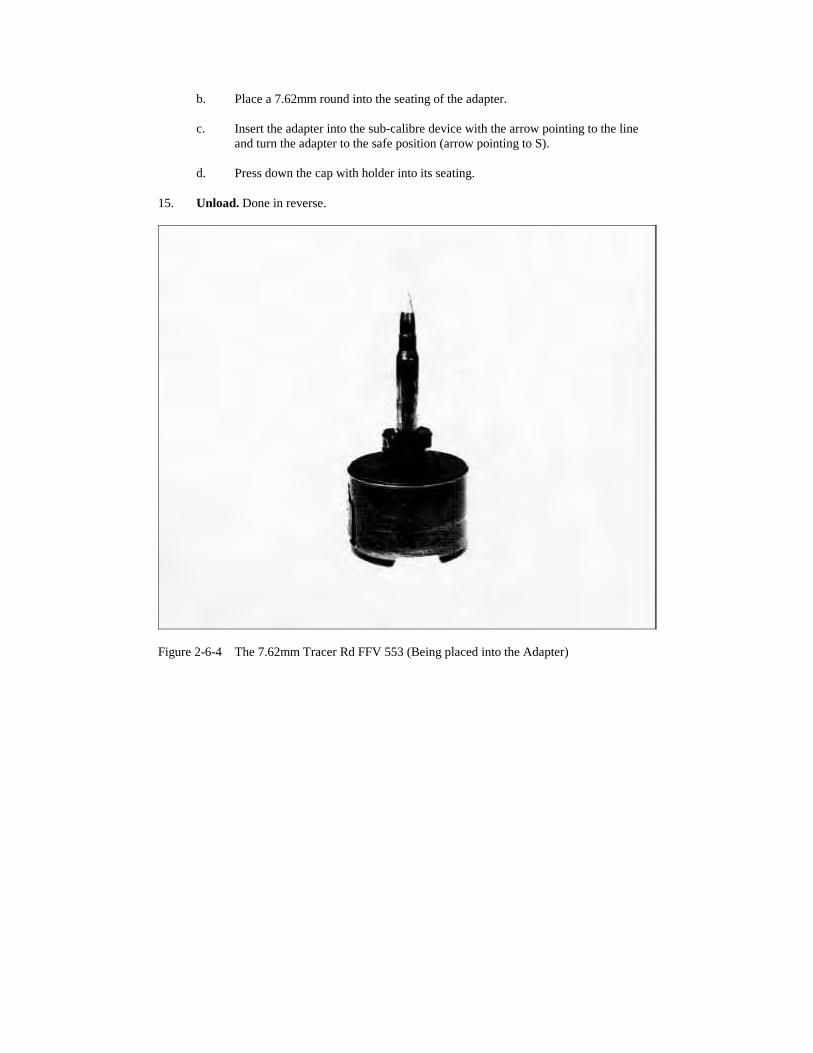
b. Place a 7.62mm round into the seating of the adapter.
c. Insert the adapter into the sub-calibre device with the arrow pointing to the lineand turn the adapter to the safe position (arrow pointing to S).
d. Press down the cap with holder into its seating.
15. Unload. Done in reverse.
Figure 2-6-4 The 7.62mm Tracer Rd FFV 553 (Being placed into the Adapter)
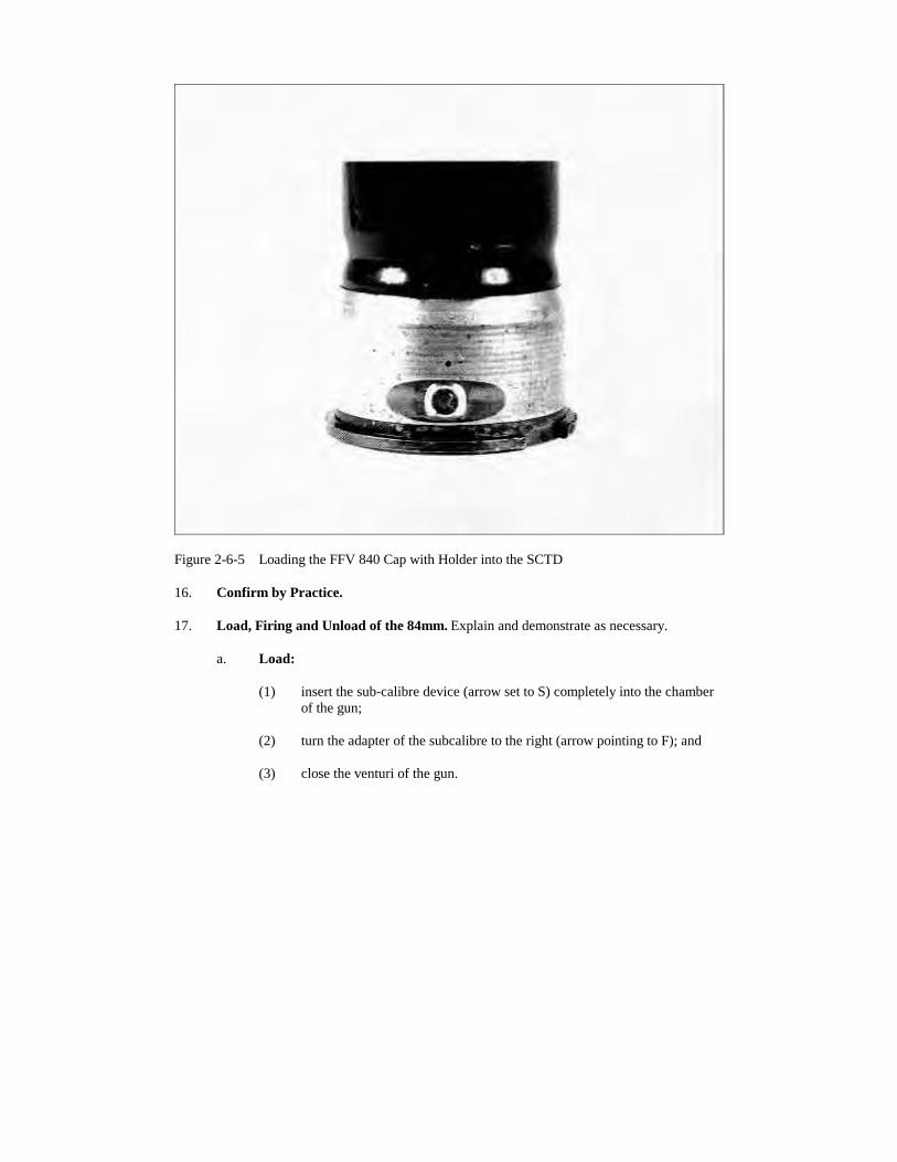
Figure 2-6-5 Loading the FFV 840 Cap with Holder into the SCTD
16. Confirm by Practice.
17. Load, Firing and Unload of the 84mm. Explain and demonstrate as necessary.
a. Load:
(1) insert the sub-calibre device (arrow set to S) completely into the chamberof the gun;
(2) turn the adapter of the subcalibre to the right (arrow pointing to F); and
(3) close the venturi of the gun.
Figure 2-6-6 Loading and Setting the SCTD into the Gun
b. Firing. The operation of the gun is the same as when firing the FFV 551 ammo.
c. Unload:
(1) cock the gun, place the safety catch at safe and keep the gun pointed in asafe direction;
(2) open venturi;
(3) set the adapter to "S";
(4) remove the subcalibre device from the gun by pushing forward the venturilocking knob; and
(5) when reloading the 84mm do the normal load as listed above.
18. Confirm by Practice.
19. Misfire Drills. Explain and demonstrate where necessary.
a. Initially the drills are as listed in lesson 4.
b. Misfire Unload. The No. 2 is to repeat "Misfire unload", unseat the device andcheck the adapter:
(1) if not set at "F" - set it to "F", reload and continue the shoot; and
(2) if set at "F" - remove the device, pass it to the No. 3. If available, reloadwith a fresh device and continue the shoot. No. 3 will unload the FFV 553.
c. Disposal. Any misfired round should be set aside and marked for return to theammo compound.
d. Suspect Device. If it is suspected that a sub-calibre device is faulty then it shouldnot be used again until examined by a weapon tech.
e. Jammed Device. If a device becomes jammed in the chamber, seek the assistanceof a weapons tech.
20. Confirm by Questions and Practice.
21. Care and Cleaning. Explain and demonstrate as necessary. After firing, considerablefouling will be left in the barrel of the gun.
a. Clean the 84mm barrel as taught.
b. Remove the adapter from the device clean the barrel using the nylon pull throughand flannelette swab size 100mm x 50mm and oil the barrel using 100mm x25mm.
c. Clean the adapter, leave slightly oiled and screw back into the device.
d. Report to the weapon tech any burrs set on the body or rim which cause difficultyin loading and do not use until rectified.
e. Return the device to its container.
22. Confirm by Questions and Practice.
23. Conclusion:
a. questions from the section on the entire lesson;
b. confirm by questions and practice;
c. safety precautions on gun and subcalibre device; and
d. pack up.
24. Summary. To include the following:
a. the importance of regarding the subcalibre training device as a weapon andhandling it as such;
b. the requirement to call in the weapon tech in the event of a jammed or suspectdevice; and
c. the need to ensure the device is in a fired condition before storage.
LESSON 7 - HANDLING
INSTRUCTOR'S NOTES
1. Aim. To teach the composition of a SRAAW(M) team in the field, the carriage ofweapons and equipment and the selection of antitank fire positions.
2. Time. Two 40 minute lessons.
3. Method. A basic instructional outdoor lesson.
4. Stores
a. 84mm complete 1 per 3 soldiers,
b. FFV 551 (DUMMY) 1 per gun,
c. Duplex ammunition container 1 set per gun,
d. 9mm pistol w/case 1 per 3 soldiers,
e. C7 2 per 3 soldiers,
f. sandbags/string sufficient to camouflage at least theSRAAW duplex containers, and
g. white tape, pegs, protractor and 200 mmeasuring tape.
5. Preparation:
a. recce the ground to be used;
b. decide on the direction of likely tank approaches and select a good fireposition/trench, defilade to the approaches;
c. peg out the dimensions of the backblast danger area; and
d. lay out the weapons and equipment sufficient to equip the section in three mangroups.
6. Miscellaneous.
a. During the practice stages detail and equip 3 man teams. The third rifleman isnormally a critic but occasionally he should act as part of the team.
b. The film "TANK KILLING" (catalogue No. 07233) 66mm film may be used as anintroduction to this lesson.
CONDUCT OF THE LESSON
7. Safety Precautions. Supervised.
8. Review:
a. the factors affecting the position for firing M72; and
b. the factors to be considered in the selection of a good rifle fire position.
9. Camouflage. The section is to carry out personal camouflage. Fit a telescopic sight toeach gun.
10. The SRAAW Team. Besides the section comd or weapons det comd, the team normallyconsists of two men equipped as follows:
a. The No. 1. He commands the team and fires the gun. He is responsible for the gunand No. 1 bag. He is armed with a C7 rifle or pistol.
b. The No. 2. He is to carry 4 x FFV 551 RAP rounds in their containers and the No.2 bag. He is armed with a C7 rifle.
11. Explain. Riflemen may be attached to carry additional ammunition and provide localprotection.
12. Camouflage. Explain and demonstrate. Sandbags, hessian or disruptive pattern materialare to be used to camouflage the gun and ammunition containers. (Using the principles applied toother small arms, securely tie string or elastic to secure additional scrim, hessian strips andnatural foliage.) Ensure free access and use of the following:
a. the muzzle and venturi;
b. venturi lock knob and lever;
c. the sight unit and field of view;
d. the trigger, front and rear housing for the mount; and
e. ammunition.
13. Confirm by Questions and Practice. (Detail two man teams, leave equipmentcamouflaged at the end of the practice stage.)
Figure 2-7-1 Camouflaged 84mm Gun
14. Carriage. Explain and demonstrate. The gun is normally carried by the No. 1 but onoccasions the No. 2 may assist. The method of carriage used will be determined by the task andthe nature of the ground and cover available. The following methods are a guide:
a. slung over the shoulder;
b. across the body, sling around the back of the neck;
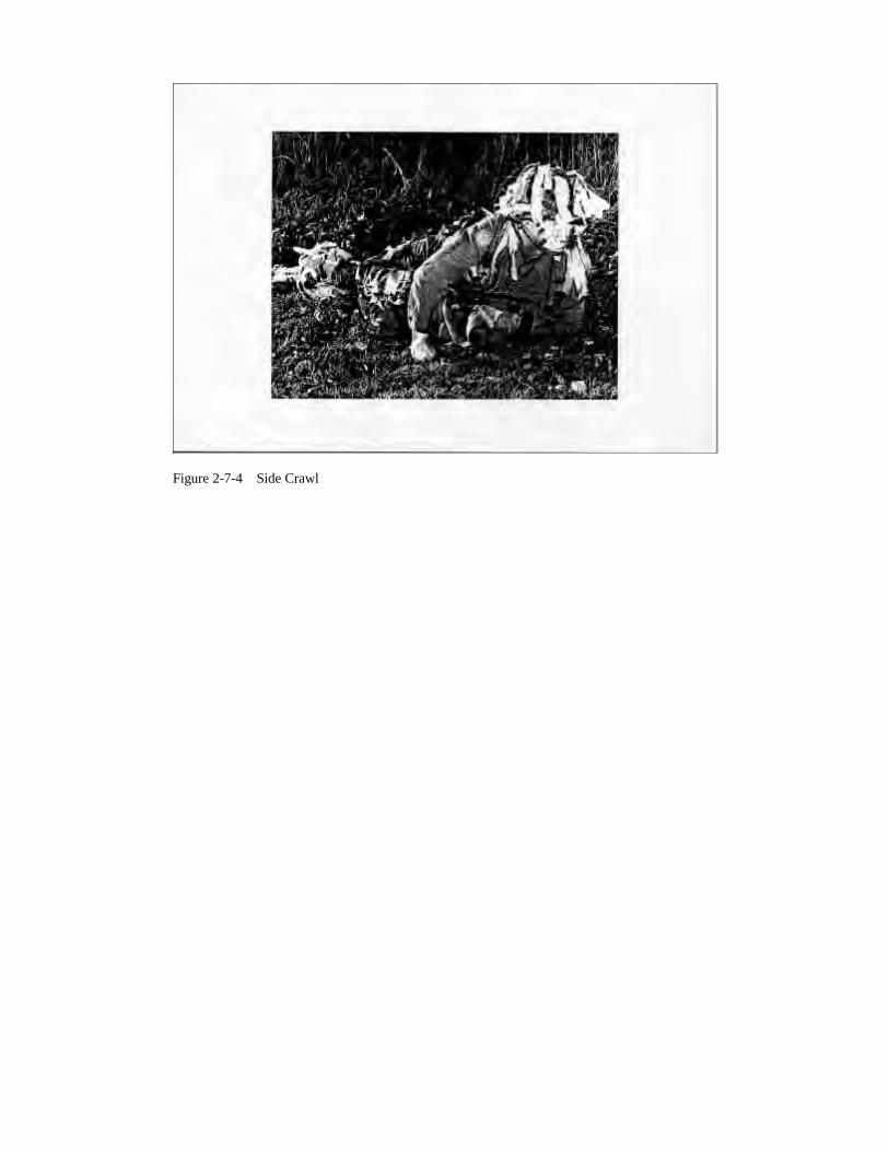
c. using the side crawl, or the leopard crawl; and
d. ammunition containers strapped to the top of the webbing yoke, or carried"suitcase style" using the duplex ammunition container harness.
Figure 2-7-2 Slung Over the Shoulder
Figure 2-7-3 Carriage Across the Body
Figure 2-7-4 Side Crawl
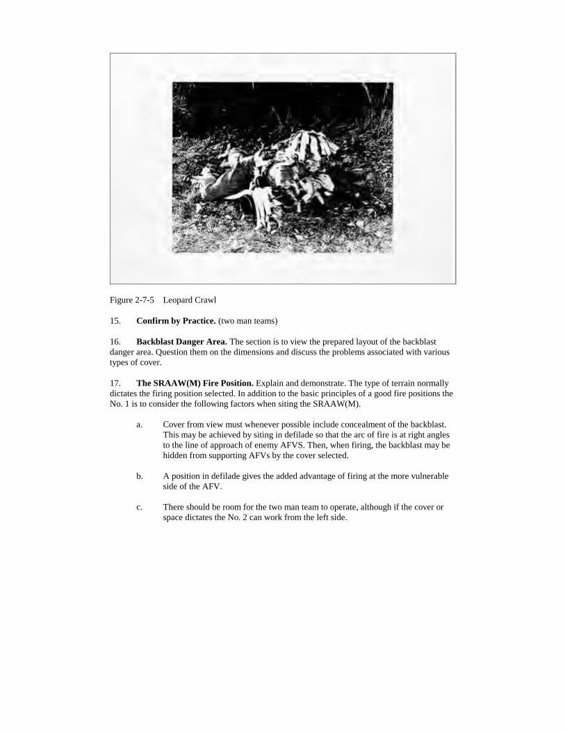
Figure 2-7-5 Leopard Crawl
15. Confirm by Practice. (two man teams)
16. Backblast Danger Area. The section is to view the prepared layout of the backblastdanger area. Question them on the dimensions and discuss the problems associated with varioustypes of cover.
17. The SRAAW(M) Fire Position. Explain and demonstrate. The type of terrain normallydictates the firing position selected. In addition to the basic principles of a good fire positions theNo. 1 is to consider the following factors when siting the SRAAW(M).
a. Cover from view must whenever possible include concealment of the backblast.This may be achieved by siting in defilade so that the arc of fire is at right anglesto the line of approach of enemy AFVS. Then, when firing, the backblast may behidden from supporting AFVs by the cover selected.
b. A position in defilade gives the added advantage of firing at the more vulnerableside of the AFV.
c. There should be room for the two man team to operate, although if the cover orspace dictates the No. 2 can work from the left side.
d. Alternate positions capable of covering the same task are to be selected.
e. Routes to alternate positions must be planned and marked, particularly in closecountry and at night.
f. Ammunition, in its containers, must be concealed yet readily available. Personalweapons must also be in hand.
g. If other riflemen are part of the team, their positions must be concealed and sitedso that they can provide the necessary local protection.
h. The No. 1 needs early warning of the approach of enemy AFVs into his arcs orkilling area. The other members of the team may be used in this role.
18. Confirm by Questions.
19. Use of Various Types of Cover. Explain. In addition to the general factors, specificmatters relating to the type of cover available must be considered.
20. The Fire Trench. Explain and demonstrate.
a. This is normally a prepared position in defence and the normal rifleman's "1"trench is suitable.
b. Position the mount in the front housing, and adjust it to suit the elbow rest and yetgive muzzle clearance over the parapet.
c. Brace the body against the rear wall of the trench. The No. 2 is to ensure that theventuri is above ground level and clear of the rear face of the trench.
d. Use the left end of the trench to enable the No. 2 to work on the right of the gunand permit storage of ammunition under the overhead cover of the trench.
e. The gun may be loaded, safety catch applied and laid front to rear across thetrench.
21. Fold in the ground and low cover. Explain and demonstrate.
a. The height of the cover may dictate the use of the lying position, therefore the sizeof the arc and the killing area may be greatly reduced.
b. Use the mount in the front housing but check carefully for muzzle clearance.
c. The need for a rising line of sight and clearance for the backblast danger area maybe difficult to achieve.
d. Low cover may require the firing position to be modified to achieve concealment.
e. Similarly the limitations of the cover may require the No. 2 to load and operatefrom the left side of the gun.
22. Build Up Areas. Explain and demonstrate.
a. Due to the problems of backblast debris and damage to hearing, confined spaces(narrow streets and rooms) should be avoided except in extreme emergency.
b. If forced to fire within a room, open all doors and windows to help reduce theeffect of overpressure.
c. Garden walls and demolished buildings provide adequate cover for use of thenormal firing positions.
d. Firing parallel to a wall may help to conceal the backblast and also provides analternative to having the wall directly behind the gun and within the backblastdanger area.
e. Again, the No. 2 may be required to operate from the left side of the gun in orderto allow the No. 1 to make maximum use of the cover.
23. Weapon Safety. Explain.
a. When moving to a planned fire position the gun may be loaded in dead groundclose to the position provided that the safety catch is at "Safe".
b. Care must be taken when occupying an alternative position quickly thatammunition and equipment are NOT positioned in the backblast danger area.
c. When preparing to move ammunition container lids must be replaced and toolsand spare parts secured in their respective bags.
24. Confirmation. Confirm practice, as follows:
a. detail and equip two man teams;
b. indicate areas of work to cater for various types of cover;
c. brief teams on the direction of enemy AFV approaches;
d. criticize siting, cover and concealment. View from the enemy position;
e. have teams move tactically from fire position to fire position and have the thirdman of each team criticize their movement; and
f. discuss the positioning of other members of the team where applicable.
25. Conclusion:
a. questions from the section on the entire lesson;
b. confirm by questions and practice;
c. normal safety precautions;
d. pack kit; and
e. Summary. To include the following:
(1) importance of teamwork;
(2) the value of defilade; and
(3) the need to balance the factors of concealment and protection with theneed effectively to cover the arc of fire and killing area.
THIS PAGE IS INTENTIONALLY LEFT BLANK
LESSON 8 - AFV RECOGNITION TRAINING
INSTRUCTOR'S NOTES
1. Aim. To teach:
a. the main component parts of AFVS;
b. factors affecting AFV recognition;
c. how to recognize different types of AFVS; and
d. to qualify AFV recognition level one.
2. Time. Two 40 minute lessons.
3. Method. A basic instructional lesson. Stores are as follows:
a. slide projector (35mm) and slides,
b. OHP and projectuals,
c. 35mm slides in carousel, and
d. screen.
4. Preparation;
a. obtain training aids and necessary equipment,
b. prepare classroom,
c. test the slide projector and OHP prior to giving the class, and
d. all vehicles mentioned in this lesson are proposals only to assist theinstructor/section commander for the preparation of the lesson.
5. Miscellaneous.
a. AFV training is divided in the three levels:
(1) Level One - all infantry soldiers and officers,
(2) Level Two - section commanders, and
(3) Level Three - members within Recce or Anti-Armour pl.
b. Anti-armour gunner (84mm) team must be very effective in recognizing potentialtargets at the weapons maximum range.
c. On achieving the basic standard, continuation training is essential as facts learnedare easily forgotten; two training classes should be organized monthly.
CONDUCT OF THE LESSON
6. Safety Precautions. Nil.
7. Review. Vulnerable areas, Lesson Three.
8. Introduction. On the modern battlefield it can no longer be assumed that all AFVs infront are enemy and all those to the rear are friendly. It is vitally important that all 84mm gunnersbe able to rapidly and accurately identify AFVs in their area. This will result in the gathering ofvital battlefield intelligence and rapid engagement of targets. In order to perfect skills required inAFV recognition, the next two lessons will be devoted to AFV recognition.
9. Main Component Parts of the AFV. As we go through our main component recognitionlesson we will be describing the AFV by using distinguishing features. Keep in mind that thesecret of effective AFV recognition is systematic inspections. When attempting to recognizeAFVs we will observe the three main component parts in the following sequence:
a. The Suspension:
(1) Main types:
(a) wheeled LUCH,
(b) tracked T64, and
(c) half tracked.
(2) Name the important parts:
(a) road wheels,
(b) sprockets,
(c) idler wheel, and
(d) support rollers.
(3) Various examples:
(a) tight track, large road wheel AMX30, and
(b) loose tracks, no support rollers, T54/55.large road wheels
b. The Hull. Normally houses the fighting compartment and the engine. Comes inmany shapes.
(b) very low, very sharp glacis, BMP1 gun, andand note parts on side, and
(c) boat shaped, high profile LVTP7(US).
c. The Turret. Normally houses the veh main armament and will have a variety ofboxes, bins, rails, etc.
(1) Name the important parts:
(a) fume extractor,
(b) muzzle brake T72 mantlet, and
(c) gun.
(2) Various examples:
(a) Leopard 1 ARV Leopard 1 ARV,
(b) AMX 30 PP Bridgelayer AMX 30 PP, and
(c) FV 180 AEV FV 180/AEV.
10. Confirm by Questions.
11. Factors Affecting AFV Recognition. Unfortunately, the AFVs you see on the battlefielddo not appear as they come out of the factory. Many things will have happened to the vehiclewhen it appears before you. Factors that affect recognition are:
a. distance,
b. visibility,
c. camouflage,
d. speed,
e. tactical employment of the veh, ie., hull down, use of dead ground,
f. restrictions imposed on observer-hatches down, NBC, fatigue etc, and
g. add on - nets, bins, boxes, spare track, rucksacks, etc.
12. Confirm by questions.
13. Recognition of Different Types of Vehicles. All AFVs are designed to do a specifictask. We have broken these down to eight categories which basically indicate a certain threat.
a. Tanks (Main Battle Tank):
(1) mounting a large direct fire gun M1 ABRAMS,on a turret
(2) very good armour protection, and
(3) fair to good mobility.
b. Recce Vehicle:
(1) tracked or wheeled Commando,
(2) mount a variety of wpns (MG to 152mm) 4K,
(3) limited protection (reduced weight) BTR 80,
(4) good to excellent mobility, and
(5) poor cross country capability in scout car.
c. Tank Destroyer:
(1) tracked or wheeled IKV 91,
(2) can carry a gun (in those cases it BRDM 2,can be mistaken for a light tank)
(3) can carry missiles (usually modified w/SPANDREL (Soviet),APC or recce vehs)
(4) limited protection, and
(5) fair to good mobility.
d. APCS:
(1) tracked or wheeled,
(2) limited protection,
(3) varied firepower, and
(4) good mobility (especially when tracked).
e. Self Propelled Guns and Howitzers:
(1) normally tracked AFV 1,
(2) limited protection,
(3) normally carrying an extreme large gun, and
(4) fair to good mobility.
f. AA (Gun and Missiles):
(1) tracked or wheeled SA8 GECKO,
(2) with some exception they are fitted Gephard,with a huge turret surmounted bya large radar
(3) if AA gun, it will have 2 or more barrels
(4) limited to good protection Chapparal, and
(5) fair to good mobility.
g. Armoured Recovery Vehicle:
(1) tracked or wheeled,
(2) instead of a turret and armament, will carry special equipment such as winchcranes, etc...,
(3) can be mistaken for an AEV because of similar equipment,
(4) fair to good protection,
(5) fair to good mobility.
h. Armoured Engineer Vehicle or Bridge Layer:
(1) normally tracked IMR,
(2) special equipment fitted to it i.e., T54/55,cranes, dozer, blades, bridge, etc.
(3) limited to good protection BGL 60, and
(4) fair to good mobility AMX 30 PP.
14. Confirm by Questions.
15. AFV Level One. All infantry soldiers and officers should be qualified level one, which istaught in this class, 84mm gunners should try to advance to level two and possibly level three.AFV standards for each level are maintained by the Advanced Anti-Armour Cell at the CombatTraining Centre.
16. Confirm by Practice (Slides).
17. Conclusion:
a. Questions from the section on the entire lesson.
b. Confirm by questions.
c. Pack up.
18. Summary.
a. Remember the purpose of this is to highlight the importance of the subject as partof a gun team.
b. A forecast of the section's next lesson in this subject.
LESSON 9 - CARTRIDGE, 84MM, HEDP FFV 502
INSTRUCTOR'S NOTES
1. Aim. To introduce and teach:
a. the 84mm HEDP round,
b. characteristics,
c. detailed description, and
d. proper setting and use.
2. Time. One 40 minute lesson.
3. Method. A basic instructional lesson.
4. Stores.
a. FFV502 HEDP rounds (inert or dummy) 4 per class,
b. duplex ammunition containers 1,
c. charts as required, and
d. gun 84mm 2 per class.
5. Preparation.
a. Ensure that the FFV502 HEDP rounds are inert or dummy.
b. Check with stores on the quantity of rounds available before you plan your lesson.
6. Miscellaneous:
a. number the section in groups of three and allocate one round per group; and
b. stress the importance of the dual purpose setting.
CONDUCT OF THE LESSON
7. Safety Precautions. To be carried out by the instructor.
8. Review. Other 84mm ammunition.
9. Introduction. The FFV502 High Explosive Dual Purpose (HEDP) round was introducedto handle the requirement for killing or incapacitating enemy personnel protected by fieldfortifications or lightly armoured vehicles. It is nicknamed THE BUNKER BUSTER.
10. Physical Characteristics.
a. The ammunition carriage for the HEDP round are very similar to the other rounds.The HEDP round are packaged similarly to the other rounds in that there are tworounds in a plastic carrying case six rounds in a wooden crate;
b. The projectile is fin stabilized with a base fuze.
c. There are two modes of operation.
11. Weights and Dimensions:
a. total weight of the round 3.3 kg,
b. weight of the duplex container with 8.3 kg,two rounds
c. length 44 cm, and
d. diameter 84mm.
12. Performance:
a. muzzle velocity 230 m/s,
b. effective range:
(1) moving hard targets 300 m,
(2) field fortification targets 500 m, and
(3) unprotected troops 1 000 m.
c. time of flight out to 300 m 1.3 s,
d. arming distance 15 - 40 m,
e. armour penetration approx 150mm, and
f. operating temperature -40ΕC to 50ΕC.
13. Markings:
a. round designator 84mm HEDP in white,
b. band on shell body bright yellow,
c. slip ring yellow,
d. tot number white,
e. the letter "1" (instantaneous) or"D" (delay) is stencilled on the sideof the shell casing in white, and
f. colour of the complete round black.
14. Confirm by Questions.
15. Shell. The shell consists of the following parts: nose cap, shell body, fin assembly andfuze system.
a. Nose Cap. The nose cap is made of aluminum.
b. Shell Body. The shell body is made of steel and designed for optimumfragmentation. The hollow charge liner is made of a special material, making forextensive behind armour damage.
c. Bursting Charge. The bursting charge is cast HMX/TNT and the booster ispressed of tetryl and RDX.
d. Fin Assembly. The fin assembly is made of aluminum alloy. The fins are foldedinside the cartridge case and unfold when the shell leaves the muzzle.
e. Fuze System. The fuze system is a combination instantaneous and delay system.The fuze mode is set when the round is loaded by keeping the desired letter, I orD, in the upright position.
16. Revised Load. Explain and demonstrate as necessary:
a. the revised load drill is as follows:
(1) the No. 1 orders "IMPACT LOAD" or "DELAY LOAD" as required, and
(2) the No. 2 repeats the order and loads the projectile with the function letter"1" or "D" up as appropriate.
b. the No. 2 must grasp the round and place one finger in the recess of the roundopposite to the correct letter. The recess is guided onto the cartridge guide; and
c. after closing the breech and ensuring the venturi is locked No. 2 orders "IMPACTREADY" or "DELAY READY" as required. The No. 1 shall repeat the order.
17. Mode Selection. The selection is made based on the type of target:
a. lightly armoured vehicles - use "1" for instantaneous;
b. heavily fortified defences - use "D" for delay. The round will penetrate beforeexploding; and
c. if there is a great chance of a ricochet use the "1" setting.
18. Confirm. Questions and practices.
19. Conclusion.
a. Take questions from class on the entire lesson.
b. Confirm by questions and practice.
c. Normal Safety Precautions.
d. Pack kit.
e. Summary including the following:
(1) the importance of selecting the correct setting for the target, and
(2) a forecast of the next lesson.
LESSON 10 - SUB-CALIBRE ADAPTER - 6.5MM
INSTRUCTOR'S NOTES
1. Aim. To teach the description, priming, unpriming, loading, unloading, misfire drills, careand cleaning of the 6.5mm device.
2. Time. One 40 minute lesson.
3. Method. A basic instructional lesson.
4. Stores:
a. 84mm complete 1 per 3 soldiers,
b. subcalibre device 3 per gun, and
c. FFV 551 DUMMY RD 1 per gun.
5. Preparation.
a. Ensure both the serial numbers on the casing and the adapter are the same.
b. Layout the section room and ensure that the guns are serviceable.
c. Check that the sub-calibre devices are serviceable.
6. Miscellaneous.
a. Number the class in groups of three and allocate one group per gun prior to safetyprecautions.
b. When demonstrating a two man crew, use a soldier from the class to act as the No.1.
c. Have boresighting stands set up outside.
CONDUCT OF LESSON
7. Safety Precautions. Normal.
8. Review. Load/unload and misfire drill.
9. Introduction. The sub-calibre device is used during the early stages of training topractice the team in loading, unloading and firing at both stationary and moving targets. Thedevice is fitted with a barrel from which a 6.5mm round is fired.
10. Description. Explain:
a. General:
(1) the 84mm can be fitted with a sub-calibre device (L1A2) for trainingpurposes;
(2) the device weighs 4 kg and is externally similar in shape to the old 84mmHEAT - T FFV 65;
(3) the loading, aiming and firing Operation is the same as with the 84mmFFV 551 and 552 ammunition;
(4) the ammunition for this sub-calibre is 6.5mm gallery and tracer; and
(5) the sub-calibre device consists of three basic components: casing, barreland adapter.
b. Components
(1) Casing. The casing is similar to the 84mm HEAT-T FFV 65. The rim atthe base is made of brass and is identical to the rim of the old FFV 65casing in shape. There are single and double lines engraved on the basemarked "S" and "F" to denote the safe and fire positions, respectively forthe adapter. The recess in the brass rim lines up with the cartridge guideon the gun. The casing is fitted with a conical sleeve which fits betweenthe rim and barrel sleeve to keep sub-calibre rounds and dirt out of theinterior of the casing.
(2) Barrel. Internally, the casing is fitted with a barrel sleeve to which thefiring mechanism is attached. The barrel is screwed into the front end ofthe sleeve and is locked by the barrel positioning screw. At the front endof the casing is a hole through which the barrel protrudes. A rubber dustcover fills in the gap between the barrel and the casing and keeps dirt outof the interior of the casing. Spaced equidistant around the casing are fourzeroing screws for aligning the barrel to the 84mm when zeroing. Thebarrel is fitted at the tip with a brass ferrule to prevent accidental damagesto the bore of the 84mm when loading.
NOTE
The barrel and barrel sleeve can be removed from the casing but only by aweapon technician. The barrel and its sleeve can be assembled 180degrees out of alignment thus causing a malfunction and damage.
(3) Adapter. The percussion type mechanism is assembled in the base of thecasing. It must be cocked before it can be withdrawn from, or placed in,the casing. This is because the two grooves in the conical sleeve containthe safety and cocking sears. When they are in the fired position, out oftheir respective cocking notches, rotation is impossible.
11. Confirm by Questions.
12. Operation. Explain and demonstrate.
a. General. The sub-calibre device is primed with a 6.5mm round while out of theweapon. This allows the entire device to be used as a standard round for loadingand live fire training;
b. Priming and Unpriming Device. To prime the device, remove the adapter,ensuring the barrel points towards the target:
(1) cock the mechanism with the cocking tool provided (Figure 2-10-1);
(2) rotate the adapter counter-clockwise;
(3) withdraw the adapter;
(4) insert the base of the 6.5mm round into the groove on the front of thebreech bolt; and
(5) replace the adapter in the base of the device with a clockwise turn until theindicator mark is opposite the letter "S".
c. Unpriming the Device:
(1) Ensure the device is pointing towards the target;
(2) Unscrew the adapter counter-clockwise;
(3) Remove the round from the groove in front of the adapter; and
(4) Replace the adapter.
13. Confirm. By practice. Leave device rimed.
Figure 2-10-1 Cocking the Mechanism with Cocking Tool
14. Loading and Unloading the Gun. Explain and demonstrate as necessary.
a. Loading:
(1) on the command "LOAD"; the No 2 is to act as taught when loading a fullcalibre round, except that the device is to be stopped 50mm short of thefully chambered position, and
(2) set the adapter to "F" and push the device fully home.
b. Unloading (if device has been fired). On the command "UNLOAD" the No 2 is toact as taught.
c. Unloading (if device has not been fired):
(1) on the command "UNLOAD" the No 2 is to tap the venturi lock nobforward to partially unseat the device;
(2) set the adapter to "S" and remove the device from the gun; and
(3) pass the device to the No 3 in the team who will either lay the device onthe ground pointed towards the target or unprime it.
15. Confirm by Practice.
16. Jammed Device. Should a device become jammed in the chamber and normal unloading
drills fail to extract it, the gun is to be placed to one side pointing towards the target. A weaponstech's assistance is required to remove the device.
17. Misfire Drills. Explain and demonstrate as necessary.
a. Initially, the drills are as listed in lesson 4 at paragraph 15.
b. On the Command "MISFIRE, UNLOAD", the No 2 repeats "MISFIREUNLOAD" and inserts the device and checks the adapter:
(1) if it is not set at "F" set to "F", reload and continue the engagement, and
(2) if set to "F" remove the device, pass to the No 3, reload with anotherdevice and continue the shoot. The No 3 will unprime the device.
c. Any misfired ammunition should be placed to one side and returned to theammunition compound for disposal.
d. If the device is faulty then it should not be used again until examined by theweapons tech.
18. Sub-calibre Tool Roll. Explain and describe the contents of the tool roll.
19. Confirm by Questions and Practice.
20. Care and Cleaning. Explain and demonstrate.
a. After firing practices, the sub-calibre adapter must be cleaned. The tools shown inFigure 2-10-2 are provided for this purpose.
b. Remove the mechanism and clean it. Clean the barrel with the brush and pullthrough using a 100 x 38mm flannelette swab.
c. After cleaning, rightly oil the device, load it into the gun and fire the mechanism.The adapter is never left cocked because this reduces the tension on the springwhich may result in misfires.
d. unload the device and return it and the cleaning tools to the container.
21. Confirm by Practice.
22. Conclusion.
a. questions from the class on the entire lesson;
b. confirm by questions and practice;
c. normal safety precautions;
d. pack kit; and
e. summary to include:
(1) the importance of regarding the sub-calibre device as a weapon andhandling it as such,
(2) the need to seek the assistance of a weapon tech in the event of a jammedor suspect device,
(3) ensuring the device is a fired condition before storage, and
(4) a forecast of the next lesson in this subject.
Figure 2-10-2 Cleaning Tools
CHAPTER 3
PRACTICE LESSONS - INTRODUCTION
GENERAL
1. All training must be progressive as unnecessary repetition is poor instructional practice.A soldier learns skills and facts in the basic lessons which should be taught only once during hisservice. He then requires practice to maintain and improve his skills.
2. The sequence of a practice lesson is:
a. REMIND - by explanation.
b. ASSESS WEAKNESS - by practice or test.
c. IMPROVE ON WEAKNESS - by practice.
d. PROGRESSIVE PRACTICE - by competitions.
3. The practice lessons in this publication are intended as a guide to exercising soldiers toimprove skills that soldiers have already learned. The instructor should plan the lesson based onan assessment of the soldiers weak points.
4. Faults should be immediately brought to the attention of the soldier and corrected.
5. It may become obvious during a practice lesson that the soldiers have failed to grasp aparticular skill or fact. In this case the instructor will have to teach that part of the lesson again.
COMPETITION
6. The incentive of competition will always help to make practice more interesting. Somepoints on conducting competitions are:
a. It may be on an individual or team basis.
b. If conducted on a team basis the instructors must ensure that the selected teamsare all fairly equal with respect to their ability. The more advanced members ofthe team will help the weaker members.
c. Marks can be awarded up to a given total, or instructors may begin with a totaland deduct marks for mistakes as the competition progresses.
d. A score chart drawn on the chalkboard or a sheet of paper on which to mark theresults should always be used as it will create interest.
e. Further interest can always be attained by making one team or individual watchanother to find faults which result in the awarding or deducting of marks.
f. Above all the instructor must make certain that competitions are simple andrealistic, i.e., that they exercise the soldiers ability to perform particular skills.
g. Within each practice lesson there is a final practice competition. Scores andstandards achieved can be assessed by the instructor and used as a basis forcontinued training and practice to correct weak points. During advanced trainingthe standard for the final practice competition is to match those laid down in theHandling Tests where applicable.
MASTER AND PUPIL
7. The master and pupil method of practice in its simplest form is for one man (the pupil) towork under the supervision of another (the master); the instructor watches both.
8. At all stages of training this stimulates interest, and attention to detail. It is particularlyuseful with large sections and in competitions.
NIGHT LESSONS
9. Practice in handling the gun by night is essential. Details are given in practice lessons 3and 5.
NBC LESSONS
10. It is important to practice handling the gun in NBC clothing. Details are given in practices6 and 7.
PRACTICE LESSON 1 - STRIPPING, CARE AND CLEANING
INSTRUCTOR'S NOTES
1. Aim. To practice the soldiers in:
a. stripping, assembling and cleaning; and
b. recognition of ammunition, safe handling and the characteristics of the gun.
2. Time. One 40 minute lesson.
3. Method. An indoor practice lesson.
4. Stores.
a. 84mm gun complete 1 per 3 soldiers,
b. 84mm dummy rounds as required, and
c. cleaning material as required.
5. Preparation.
a. Fit telescopic sights to all guns.
b. Prepare a chalkboard for the final practice competition as follows:
NAME STRIPPING ASSEMBLING CLEANING SAFE HANDLINGAND
CHARACTERISTICS
TOTAL
c. To score, record the number of mistakes made in each test. The soldier or teamwith the lowest combined totals for all the tests is the winner. Winners ofindividual tests can also be determined.
6. Miscellaneous:
a. at no time during this practice period is any skill to be timed;
b. teaching is only to be done when considered absolutely necessary; and
c. questions for the section on handling and safe handling are to be carefully plannedand should be general questions not related to skills.
CONDUCT OF THE LESSON
7. Safety Precautions. Inspect all guns and ammunition and sub calibre devices. Done bythe instructor.
8. Review. Nil.
9. Introduction. The 84mm SRAAW(M) team must take care to ensure that the gun is wellcleaned and correctly assembled. Negligence could lead to the gun failing to operate at a criticaltime. Practice in these skills will improve the teams ability to achieve a first round kill.
SUGGESTED PRACTICES
10. Stripping and Assembling.
a. Practice the section in stripping the gun, each man removing only one part at atime.
b. Practice assembling the gun in the same way.
c. Each man is then practiced in stripping and assembling the gun completely.
d. Leave the guns stripped at the end of the practice.
11. Description of the Gun.
a. With the guns stripped, question the section on the names of various parts.
b. Questions on characteristics, to include:
(1) dimensions of back blast area,
(2) maximum effective range, and
(3) roles of the guns.
12. Cleaning:
a. practice the section in cleaning;
b. question the section in cleaning in adverse conditions and the use of the contentsof the No.2 bag; and
c. assemble the guns.
13. Ammunition and Safe Handling. Question the section on the recognition of all types ofammunition and on safe handling.
FINAL PRACTICE
14. A suggested method of conducting the final practice is a competition as follows:
a. divide the section into two or three teams, each soldier checking an opposing teammember;
b. practice each team in turn in stripping, assembling, cleaning, safe handling andcharacteristics; and
c. record individual and team scores on the chalkboard.
CONCLUSION
15. End of Lesson Drill:
a. questions from the section on the entire lesson;
b. normal safety precautions;
c. pack kit; and
d. summary to include the following:
(1) the overall standard achieved and any weak points, and
(2) a forecast of the sections next lesson.
THIS PAGE IS INTENTIONALLY LEFT BLANK
PRACTICE LESSON 2 - FIRING POSITIONS, LOADING, UNLOADING AND AIMING
GENERAL
1. Aim. To practice the soldiers in:
a. loading and unloading in various firing positions; and
b. aiming at stationary and moving targets using the telescopic and open sights.
2. Time. One 40 minute lesson.
3. Method. An indoor or outdoor practice lesson.
4. Stores.
a. 84mm gun complete 1 per 3 soldiers,
b. 84mm drill rounds as required,
c. duplex ammunition containers 1 per gun,
d. aiming aids as required,
e. AFV recognition cards as required, and
f. stopwatch 1
5. Preparation.
a. Check that the stopwatch is serviceable.
b. Chamber test all drill rounds to ensure drill rounds chamber properly.
c. Prepare a chalkboard for the final practice competition as follows:
LOADING ANDUNLOADING HPS 10
AIMING AND SIGHTSETTING HPS15NAME
NO 1 NO 2 PROB 1 PROB 2 PROB 3TOTALHPS 25
d. To score in loading and unloading deduct one point for each drill error and onepoint for each second over the time limit. To score in aiming and sightsetting deduct five points for each incorrect answer. Winners of theindividual test can also be determined.
6. Miscellaneous. Teaching is only to be done when considered absolutely necessary.
CONDUCT OF THE LESSON - PRELIMINARIES
7. Safety Precautions. Normal.
8. Review. Nil.
9. Introduction. In battle the gun team can only be effective if it is capable of selectinggood fire positions, accurate sighting and able to load and unload the gun instinctively. Thisrequires a great deal of practice.
SUGGESTED PRACTICES
10. Loading and Unloading:
a. practice members of the section in loading and unloading in all firing positions,initially without a time limit, in order to check correct drills; and
b. alternate roles within the section until each soldier has practiced the duties as No.1 and No. 2.
11. Sight Setting:
a. practice members of the section in setting sights to varying ranges on bothtelescopic and iron sights; and
b. use other section members to check for any errors.
12. Aiming:
a. Question the section on the vulnerable areas of the various types of AFV.
b. Further questions on correct points of aim allowing for speed and direction ofmovement.
c. Include problems associated with both telescopic and iron sights.
FINAL PRACTICE
13. A suggested method of conducting the final practice as a competition is as follows:
a. Within each gun team practice each member as No. 1 and No. 2 in loading andunloading. Score as suggested in paragraph 5.d.
b. Set three problems on aiming at moving targets, two with telescopic and one withthe iron sight. The section should illustrate answers using individual aiming aids.
c. Record individual and team results on the chalkboard.
CONCLUSION
14. End of Lesson Drill:
a. Questions from the section on the entire lesson,
b. Normal safety precautions,
c. Pack kit, and
d. Summary to include the following:
(1) the overall standard achieved and any weak points, and
(2) a forecast of the sections next lesson.
THIS PAGE IS INTENTIONALLY LEFT BLANK
PRACTICE LESSON 3 - SAFETY, STRIPPING, ASSEMBLING AND GUN DRILLS ATNIGHT
INSTRUCTOR'S NOTES - GENERAL
1. Aim. To practice the soldiers at night in:
a. safety,
b. stripping and assembling, and
c. loading and unloading in different firing positions.
2. Time. One 40 minute lesson.
3. Method. Conduct the practice lesson outdoors at night or indoors with the lights off.
4. Stores.
a. 84mm gun complete 1 per 3 soldiers,
b. 84mm drill rounds as required,
c. 84mm duplex ammunition containers as required, and
d. AN PVS 5A 1
5. Preparation:
a. prepare the training area or classroom;
b. chamber test all drill rounds;
c. ensure viewing device is available and in working order;
d. prepare a chalkboard for the final practice competition as follows:
NAME STRIPPING & ASSEMBLINGHPS 15
LOADING & UNLOADINGHPS 25
TOTALHPS 40
e. to score, deduct one point for each mistake and five points for each safety error.
6. Miscellaneous:
a. when carrying out normal safety precautions extend the requirement by practicingeach member of the section; and
b. number the section in groups of three, allocate each group to a gun and explainthe system of change around.
CONDUCT OF THE LESSON - PRELIMINARIES
7. Safety Precautions. Normal.
8. Review. Nil.
9. Introduction. In battle, much of the soldiers weapon handling will be done at night. If heis to function effectively during the hours of darkness, it is essential that the soldier is practicedin basic handling drills under these conditions.
SUGGESTED PRACTICES
10. Stripping and Assembling. Practice the section in stripping and assembling the guncompletely.
11. Loading, Unloading and Safe Handling.
a. Practice the section in loading and unloading in all fire positions.
b. Introduce black blast area "not clear", and damaged round or over gauged round.
FINAL PRACTICE
12. A suggested method of conducting the final practice as a competition is as follows:
a. divide the section into teams, each team is to check the faults of an opposingteam;
b. practice each team in turn in "stripping, assembling" and "loading and unloading";and
c. record team results.
CONCLUSION
13. End of Lesson Drill:
a. questions from the section on the entire lesson,
b. further practice as time permits,
c. normal safety precautions,
d. pack kit, and
e. summary to include the following:
(1) the overall standard achieved and any weak points,
(2) emphasize the importance of night training, and
(3) a forecast of the sections next lesson in relation to this subject.
PRACTICE LESSON 4 - FIRING, MISFIRE DRILLS
INSTRUCTOR'S NOTES - GENERAL
1. Aim. To practice the soldier in:
a. firing drills; and
b. action should the gun fail to fire.
2. Time. One 40 minute lesson.
3. Method. An indoor or outdoor practice lesson.
4. Stores.
a. 84mm complete 1 per 3 soldiers,
b. 84mm drill rounds 2 per gun,
c. duplex ammunition containers 1 per gun, and
d. armour representative targets as required.
5. Preparation:
a. fit a telescope to each gun;
b. position representative targets;
c. chamber test all drill rounds; and
d. prepare a chalkboard for the final practice competition as follows:
TEAM FIRING DRILLS HPS 10 MISFIRE DRILLS HPS 10 TOTAL HPS 20
6. Miscellaneous.
a. Although neither the final practice competition or the training test has a time limit,the section should be encouraged to conduct actions quickly when dealing withmisfires quickly.
b. The 15 second waiting time may be reduced for training expedience. Theinstructor orders "Time Up" when he considers it appropriate.
c. Be continually looking for mistakes in any drills during target engagement anddeduct marks accordingly.
d. Number the section in groups of three. Allocate each group to a gun and explainthe system of change around.
e. During the practice of misfires drills use the commands "MISFIRE", "TIME UP"to the No. 1 and "LIGHTLY STRUCK", or "NOT STRUCK" to the No. 2.
CONDUCT OF THE LESSON - PRELIMINARIES
7. Safety Precautions. Normal.
8. Review. Nil.
9. Introduction. The techniques of firing the weapon must be mastered by both members ofthe team. Should the gun fail to fire actions must be done quickly and instinctively. Survivalcould depend upon it.
SUGGESTED PRACTICES
10. Firing. Practice the section in all firing positions in the following:
a. the firing drill (indicate the target, the direction of movement, range and speed);and
b. corrections (plot the fall of shot) and rapid reloading.
11. Action should the gun fail to fire. Practice the section in various firing positions in thefollowing:
a. the initial drill on a failure to fire; and
b. the subsequent drill if the gun still fails to fire. Give the necessary orders toindicate a:
(1) "FAULTY ROUND", and
(2) "DAMAGED OR BROKEN PART".
12. Final Practice. A suggested method of conducting the final practice as a competition isas follows:
a. divide the section into teams, each team fault checking an opposing team;
b. practice each team in firing drills and misfire drills; and
c. record team scores on a board.
CONCLUSION
13. End of Lesson Drill:
a. questions from the section on the entire lesson,
b. normal safety precaution,
c. pack kit,
d. summary to include the following:
(1) the overall standard achieved and any weak points, and
(2) a forecast of the sections next lesson in this subject.
PRACTICE LESSON 5 - TACTICAL HANDLING AT NIGHT
INSTRUCTOR'S NOTES - GENERAL
1. Aim. To practice the SRAAW(M) team at night as part of the section in:
a. camouflage, movement and selection of a fire position,
b. tank hunting, and
c. operating in a tank ambush.
2. Time. One 40 minute lesson by day (preparation and briefing) followed by two 40 minutepractice lessons at night.
3. Method. An outdoor practice exercise by night.
4. Stores.
a. 84mm gun complete 1 per section (additional weaponswill be required for the camouflageand movements phase and forambush drills if more than oneSRAAW(M) team is to beexercised),
b. 84mm drill rounds 2 per SRAAW(M),
c. duplex ammunition containers 2 per SRAAW(M),
d. C7 weapons with EIS 1 per rifleman,
e. C9 weapon with EIS 2 per section,
f. SRAAW(L) drill weapon 2 per section,
g. vehicle and driver 1,
h. radios 2,
i. material to cam eqpt as required, and
j. night viewing device.
5. Preparation.
a. Recce the ground and select positions for the vehicle for tank hunting. Selectrealistic tank lines of approach, ambush positions and killing areas.
b. Brief the vehicle driver on his actions and the method of communication.
c. Fit telescopic sights, layout the SRAAW(M) team equipment and weapons bygroups including drill rounds and camouflage material.
d. Chamber test all the drill rounds.
e. Prepare a paper on clipboard as follows:
TEAM ANAME/FAULTS
TEAM BNAME/FAULTS
TEAM CNAME/FAULTS
f. To score deduct one point for each mistake and five points for each safety error.
9. Ensure viewing device is available and in working order.
CONDUCT OF THE LESSON - PRELIMINARIES
6. Safety Precautions. Normal.
7. Review. Nil.
8. Introduction. When dealing with an armour threat at night the SRAAW(M) team mustbe able to conduct themselves effectively by using the ground to carry out any movement and tohandle the gun instinctively in the dark. The team must also understand the tactics of tankstalking and the setting of a tank ambush by night.
SUGGESTED PRACTICE BY DAY
9. Camouflage and Movement. Allocate personal weapons to the SRAAW(M) teams.Practice the teams in the following:
a. camouflage - personal, weapons and ammunition containers;
b. methods of carriage and movement across varied types of ground and obstacles;
c. weapon handling drills - to ensure the operability of camouflaged weapons; and
d. change gun numbers and do the practice again.
10. Tactical Knowledge. Relating to the chosen area of ground. Question the section on thefollowing:
a. characteristics of a good SRAAW(M) fire position;
b. the factors to be considered and the information needed to plan and carry out tankhunting; and
c. the factors to be considered when setting a tank ambush.
DAYLIGHT PREPARATION FOR NIGHT PRACTICE
11. General. The groups are to be equipped as a section. Section Instructors to act as sectioncommanders.
12. Daylight Briefing - Tank Hunting. Position the vehicle, brief the driver and any criticsbeing used as enemy. Brief the section on the following:
a. the tactical setting,
b. the aim,
c. final fire position - alternate position,
d. likely line of approach and bounds,
e. the section formation,
f. fire position for rifleman and C9's - local protection,
g. means of communication and signals, and
h. consolidation point or RV.
13. Daylight Briefing - Tank Ambush. Position the vehicle, brief the driver on his line ofapproach and the signal to move. Brief the section on the following:
a. the tactical setting,
b. likely lines of enemy AFV approach,
c. selection of ambush positions,
d. any OPs required,
e. position of C9's and SRAAW(L) if used,
f. communication and signals, and
g. consolidation and RV.
NIGHT PRACTICE
14. Brief the driver and critics and allow them time to move into position. The SRAAW(M)team and section are to prepare in safe area. Conduct the practice and debrief the section and anycritics used.
15. Organize the section, detail a different SRAAW(M) team and repeat exercise.
16. Final Practice. A suggested method of conducting the final practice is to organize asimple competition requiring teams to:
a. stalk to a fire position using various methods of movement;
b. judge distance and fire from these positions;
c. move to an alternative ambush position;
d. each team checks the faults of the opposing team; and
e. practice each team and record scores on the scoresheet.
CONCLUSION
17. End of Lesson Drills:
a. questions from the section on the entire lesson,
b. normal safety precautions,
c. pack kit,
d. summary to include the following:
(1) the overall standard achieved and any weak points, and
(2) a forecast of the sections next lesson in this subject.
PRACTICE LESSON 6 - NBCD HANDLING
INSTRUCTOR'S NOTES - GENERAL
1. Aim. To practice the soldier under NBC conditions in:
a. loading and unloading in various fire positions;
b. aiming at stationary and moving targets using telescopic and iron sights; and
c. firing and misfire drills.
2. Time. One 40 minute lesson.
3. Method. Indoor/outdoor practice lesson.
4. Stores.
a. NBC kit complete 1 per soldier,
b. 84mm gun 1 per 3 soldiers,
c. 84mm drill rounds 2 per gun,
d. duplex ammunition containers as required,
e. AFV recognition posters as required,
f. representative targets as required, and
g. stopwatch 1
5. Preparation:
a. Check that the stopwatch is serviceable.
b. Chamber test all drill rounds.
c. Fit telescope to each gun.
d. Position representative targets.
e. Prepare chalkboard for the final practice as follows:
TEAM LOADING/UNLOADINGHPS 20
AIMING/FIRING HPS10
MISFIRE DRILL HPS20
TOTAL HPS50
f. To score the loading and unloading, deduct one point for each error in drill andone point for each second over the time limit. To score in the aiming and firingdeduct points for inaccurate sight setting and errors in drill. To score the misfiredrills deduct one point for each mistake and five points for each safety error.
6. Miscellaneous.
a. Although the final practice competition in firing and misfire drills carries no timelimit, the section should be encouraged to complete drills quickly, except whenstripping and assembling required during misfire drills.
b. During TOPP HIGH practice have other gun detachments at TOPP MEDIUM tocheck faults.
CONDUCT OF THE LESSON - PRELIMINARIES
7. Safety Precautions. Supervised.
8. Review. Nil.
9. Introduction. Lessons taught initially and the related practice lessons will instillconfidence in the operating procedures required to achieve battle effectiveness with the gun inNBC conditions. The drills are the same, except the difficulty of carrying out the drills in anNBC suit. Consistent practice will be required to become operationally effective under theseconditions.
SUGGEST PRACTICE
10. Loading and Unloading. (state "TOPP MEDIUM" and then "TOPP HIGH"):
a. Do not impose a time limit initially to allow gun crews to gain confidence.
b. Alternate within the section until each soldier has practiced the duties as No. 1and No. 2 on the gun.
c. Repeat the practice under state "TOPP HIGH" conditions and later introduce atime limit.
11. Sight Setting, Aiming and Firing.
a. Practice the section in setting sights to varying ranges on both telescopic and ironsights.
b. Practice the gun numbers in aiming and firing with the telescopic and iron sightsat stationary and moving targets.
c. Use critics to check for errors.
12. Action Should Gun Fail to Fire. Practice the section in the various fire positions in thefollowing:
a. The initial drill on a failure to fire.
b. The subsequent drill if the gun still fails to fire giving the necessary orders toindicate:
(1) a faulty round, and
(2) a damaged or broken part.
FINAL PRACTICE
13. A suggested method of conducting the final practice as a competition is as follows:
a. Practice gun teams in loading and unloading. Score as suggested in para 5 above.
b. Conduct a practice in aiming and firing paying particular attention to the accuratesetting of sights and scoring as suggested in para 5 above.
c. Practice each team in firing drills and misfire drills. Score as suggested in para 5above.
d. Record team results on score board.
CONCLUSION
14. End of Lessons Drills:
a. questions from the section on the entire lesson,
b. normal safety precautions,
c. pack kit,
d. summary to include the following:
(1) the overall standard achieved and any weak points, and
(2) a forecast of the sections next lesson on this subject.
THIS PAGE IS INTENTIONALLY LEFT BLANK
PRACTICE LESSON 7 - NBC TACTICAL HANDLING
INSTRUCTOR'S NOTES - GENERAL
1. Aim. To practice the SRAAW(M) team under NBC conditions, as part of the section, in:
a. movement and selection of a fire position,
b. tank hunting, and
c. operation in a tank ambush.
2. Time. Two 40 minute periods.
3. Method. Outdoor practice period.
4. Stores.
a. NBC kit complete 1 set per soldier,
b. 84mm gun complete 1 per section (additional weaponswill be required for the camouflageand movement phase and for ambushdrills if more than one SRAAW(M)team is to be exercised),
c. 84mm drill rounds 4 per gun,
d. duplex ammunition containers 2 per gun,
e. C7 1 per rifleman,
f. C9 2 per section,
g. SRAAW(L) drill weapon 2 per section,
h. vehicle and driver 1,
i. radios (77 set) 2, and
j. camouflage material as required.
5. Preparation.
a. Recce the ground and select positions for the vehicle for tank hunting. Selectrealistic tank lines of approach, ambush positions and killing areas.
b. Brief the vehicle driver on his actions as the enemy vehicle driver and the methodof communication.
c. Fit telescopic sights, lay out the SRAAW(M) team equipment and weapons bygroups including drill rounds and camouflage material.
d. Chamber test all drill rounds.
e. Prepare a score sheet as follows for the final competition:
TEAM A TEAM B TEAM C
NAME FAULTS NAME FAULTS NAME FAULTS
6. Miscellaneous:
a. Number the section in groups of three and allocate each group to a gun for theinitial movement and selection of a fire positions. Then prepare the groups as asection for either the tank hunting or setting an ambush.
b. Alternate members of each group through the duties of No. 1, No. 2 and criticthroughout the practice.
CONDUCT OF THE LESSON - PRELIMINARIES
7. Safety Precautions. Normal.
8. Review. Nil.
9. Equipment. The section is to adopt NBC state TOPP LOW.
INTRODUCTION
10. The principle of "one round - one kill" has to be maintained even under NBC conditions.The armoured threat could well be even more evident at such times. Only with persistent practicein NBC clothing will the required weapons handling standard be achieved.
SUGGESTED PRACTICES
11. Movement and Selection of Fire Positions. Allocate personal weapons to theSRAAW(M) teams. Detail critics. Practice the teams in the following:
a. methods of carriage and movement across varied types of ground;
b. adoption of various types of fire positions and weapon handling drills; and
c. change the gun numbers and critics and conduct the practice again.
12. Tank Hunting. The group is to be equipped as a section. Section Instructor is to act assection commander. Position the enemy vehicle, brief the driver and any critics. Brief the sectionin the same manner as para 12, page 3-5-3.
13. Tank Ambush. Position the vehicle and brief on his line of approach and signal to move.Brief the section in the same manner as in para 13, page 3-5-3.
FINAL PRACTICE
14. Do this in the same manner as paras 12 and 13, page 3-5-3.
CONCLUSION
15. End of Lesson Drill:
a. questions from the section on the entire lesson,
b. normal safety precaution,
c. pack kit, and
d. summary to include the following:
(1) the overall standard achieved and any weak points, and
(2) a forecast of the sections next lesson in this subject.
THIS PAGE IS INTENTIONALLY LEFT BLANK
CHAPTER 4
INFORMATION FOR INSTRUCTORS
SECTION 1
DESCRIPTION AMMUNITION STRIPPING
GENERAL
1. It may be necessary, working in extreme conditions of sand or dust, to strip and cleanareas of the gun which have not been previously taught. Such further stripping is to be carried outonly by those officers and NCOs who have received instruction on the subject on a recognizedcourse. The information for the instructor is provided as general information and is not to betaught on basic skill lessons.
2. Data. Not all of the data contained in this article is of importance to the infantry soldierand provided as supporting information for instructors.
3. General Data.
a. Total weight of weapon with cleaning equipment, tools, gun board, and gun cover(canvas), approximately, 30 kg.
b. Weight of the weapon with face pad and sling, 14.3 kg.
c. Weight of mount, .91 kg.
d. Weight of telescopic sight unit, .91 kg.
e. Weight of gun with mount and telescopic sight unit, 16.2 kg.
f. Length of gun 84 cm.
4. Barrel.
a. Bore. Made up of land and grooves:
(1) diameter, 84mm,
(2) twist of rifling, right hand, uniform 1 turn in 43 calibres, and
(3) length of barrel 84.3 cm.
Figure 4-1 Barrel
5. Description.
a. The barrel, Figure 4-1, is a forged steel tube which is shaped internally at the rearend to form a chamber. From the front of the chamber the barrel is rifled out to themuzzle. The rear end of the barrel is enlarged in diameter. Externally, the rightside has a guide over which the venturi guideway locates in the closed position.Secured to the bottom of the rear face is a triangular-shaped projection whichguides the cartridge rim into its seating. It has a stop face to limit the openingmovement of the venturi. On the left side of the barrel two keyways, one wide andone narrow, hold the telescope sight mount and rear sight bracket support. At thefront of the barrel a projection forms a housing for the front sight. Two slingswivels are fitted to the barrel for carrying purposes.
Figure 4-2 Venturi
b. The venturi, Figure 4-2, is in the form of a cone-shaped cylinder. At the rear end,it is fitted with a rubber band to reduce the metallic sounds which wouldoccur when closing the venturi. Formed between two lugs is a rim which,on one side of the venturi, is cut away to fit over the cartridge guide.
Figure 4-3 Venturi Lock
c. The venturi lock, Figure 4-3, is semi-circular in shape and has a knob at the top tofacilitate movement. At the rear of the housing, the lock is fitted with asafety projection which prevents the gun from being fired while theventuri is open, or before it is fully locked in the closed position. Theventuri is locked in the closed position by the venturi lock.
6. Ammunition.
a. Cartridge 84mm, HEAT RAP FFV 551.
(1) The shell is fin stabilized and rotates slowly during flight. The rocketmotor assist enables the shell to obtain a flat trajectory over it's short timeof flight.
(2) The hollow charge explosive filling plus a piezo electric fusing systemenables the shell to function at large angles of impact with highpenetrating power. Safety features are included in the fusing system whichallow the shell to be fired through brush and scrub without igniting.
(3) The cartridge has the following characteristics:
(a) maximum range up to 700 m,
(b) time of flight to, - 400 m 1.3 sec- 500 m 1.6 sec- 600 m 1.9 sec- 700 m 2.2 sec
(c) arming distance 5 to 15 m,
(d) maximum angle of impact 80Ε to normal impact,
(e) penetration, solid armour 400mm, and
(f) operating temperature range, -40 C to + 60 C.
7. Description. The projectile assembly consists of the following main parts:
a. Nose. This consists of a plastic ballistic cap and a light alloy distance tube (shocktransmitter). The front end of the distance tube is fitted with an edge of steel todecrease the natural tendency of a shell to slip from the point of impact.
b. Projectile Body. The body is made of light alloy and contains a bursting chargeconsisting of 500 grams of octol, a copper liner and a booster. The booster is pressloaded with 8 grams of tetryl.
c. Fuze:
(1) The fuze system has a pressure activated (piezo) generator, an armingdevice with an electric detonator and an inflight safety device.
(2) To prevent accidental arming of the rotor in the arming device, there aretwo mechanical safety devices which function independently of eachother.
(3) Rocket Motor:
(a) The motor body is made of light alloy. The base of the shell formsthe front closure of the rocket chamber. The aft closure, also oflight alloy, has a rocket motor nozzle and contains the delay unitand the ignition charge. The rocket motor charge consists of about300 grams of smokeless double base propellant.
(b) On firing, the propellant gases ignite the delay composition whichin turn ignites the ignition charge of the rocket motor through thedelay unit intermediate charge. The ignition charge then ignites therocket motor charge and the pressure rises. To ensure effectiveignition of the rocket propellant, the delay unit has been designedto leave the nozzle when the motor pressure exceeds apredetermined figure. The shell is then about 18 metres in front ofthe gun. On leaving the nozzle, the delay unit continues forward inthe line of fire at slow speed. The rocket motor propellant burns for1.5 seconds.
d. Stabilizing Unit. This unit is fitted to the aft closure of the rocket motor duringassembly of the cartridge and consists of a light alloy fin section and a plungerdevice with two non return gas valves.
e. Slipping Ring. This teflon ring is located externally between the aft closure of therocket motor and the stabilizing unit. Although the shell is fired from a rifledbarrel, the slipping ring ensures that the rate of spin does not reach a rotation thatwhich would degrade the fin stabilization of the shell or the hollow-chargeperformance of the high explosive.
8. Cartridge 84mm TP RAP FFV 552
a. Performance. The Target Practice (TP) projectile FFV 552 is the practice versionof the HEAT round FFV 551 and has the same ballistic characteristics.
b. The practice projectile resembles the HEAT counterpart only in the area of therocket motor and aft closure. The remaining components are made largely from
aluminum alloy and contain no explosives. The weight of the omitted explosivesare made up by using a thick walled forward portion.
9. Additional Stripping and Assembling. Additional stripping of the weapon may be doneunder supervision by a NCO or officer with the correct qualifications as follows.
a. Remove the screw and retaining leaf spring from the trigger, and sear axis pins.Remove the safety catch, withdraw the axis pins and remove the trigger with itsspring the and sear with its spring.
b. Unscrew the extractor axis screw and remove the extractor with spring. Separatethe extractor and spring by removing the screw.
c. Assembly is in reverse order, care must be taken when replacing the sear toensure the claw is towards the venturi, with the spring towards the barrel.
d. Using the sight adjusting tool, remove the retaining nut and push out the pivot pin.Assemble in the reverse order.
e. Remove the extractor retaining screw and remove the spring assemble in reverseorder.
Figure 4-4 Basic Stripping
Figure 4-5 Removing Retaining Leaf Spring Safety Catch - Trigger and Sear
Figure 4-6 To Remove Extractor and Spring
10. Cleaning. After carrying out cleaning before firing, the clearance between the front faceof the venturi and the rear face of the breech at the venturi axis screw must be checked.With the venturi in the open position the 0.25mm venturi clearance gauge "No Go" isheld against the joint, see Figure 4-7. It should not be possible to insert the gauge into thejoint. If it can be inserted, the unit weapons technician must be informed and adjustmentmade to the setting of the venturi axis screw.
Figure 4-7 Checking Venturi
11. Number two spare part bag, which also has one metal spare parts box, contains the itemslisted in figure 4-8.
Figure 4-8 Spare Parts and Box
12. General.
a. The use of the subcalibre adapter is an economical way in which to practiceweapon crews in engaging targets and weapon drills. In addition, weapon crewsbecome familiar with the weapon prior to firing full-calibre ammunition. Toobtain best results, the subcalibre adapter must be zeroed to the gun with which itis normally used.
b. Adjustment During Zero:
(1) There are four zeroing screws at right angles around the front of the casingof the adapter held by grub screws through the front of the casing. Copperlocking plugs are placed between the grub screws and zeroing screws, toavoid damaging the zeroing screws. The zeroing screws are in opposingpairs and adjustment of these screws will move the MPI laterally andvertically.
(2) Before adjustments are made on the zeroing screws, the grub screws mustbe loosened and after every adjustment they must be tightened.
To adjust the MPI always move the barrel in the direction the shot is to go that is, if the MPI is tomove to the right, loosen the right hand screw and tighten the left.
(4) One half turn of the zeroing screws will move the MPI approximately250mm at 100 metres. A correctly zeroed adapter will have the MPI fallon the CZP which is level with the point of aim and 100mm to the right ofit. This compensates for the distance between the line of sight and axis ofthe barrel which are theoretically parallel after boresighting. Thepermissible variation at 100m is 100mm in all directions from the CZP.
(5) Both the casing and adapter are numbered; hence prior to use, ensure thatthe numbers correspond.
(6) The correct sequence of zeroing is to first rough zero and then zero, asdescribed in the present chapter. The gun must be boresighted beforestarting.
c. Rough Zeroing the Device. Explain and demonstrate:
(1) Place the front boresight in the muzzle of the weapon. Remove the adapterfrom the device and place the device in the weapon. Close the venturi andplace the rear boresight in the back of the venturi.
(2) Sight through the rear boresight down the barrel of the device to themuzzle boresight. Remove the device and bring the centre of the barrelonto the centre of the front boresight with the zeroing screws by trial anderror. Replace and remove as necessary.
d. Zeroing. Explain and demonstrate:
(1) prepare the device for firing and carry out loading drills,
(2) with the telescopic sight unit set at 100 metres fire a three round group,
(3) check the MPI of the group and make lateral and vertical adjustments asnecessary to superimpose the MPI on the CZP. Fire a three round groupafter each adjustments,
(4) when the zero has been established with the telescopic sight unit, a groupshould be fired using the open sight to check its zero. If it has beenboresighted correctly, it should be aligned, and
(5) the 6.5mm tracer projectile does not conform exactly to full calibreballistics at all ranges.
13. Subcalibre Firing Mechanism.
a. Cocking Action:
(1) By drawing back on the cocking cap with the cocking tool, the entire firingpin housing is drawn to the rear. This compresses the firing pin springbetween the firing pin and the firing spring rear seating.
(2) When the firing pin housing has been drawn approximately half way to therear, the hooked end of the safety sear clears its safety cocking notch,allowing it to rotate under the influence of its sear spring so that thehooked end is in front of and in line with its safety cocking notch. Thisprevents the accidental firing of the device.
(3) When the firing pin housing has been drawn fully to the rear of the toe ofthe cocking sear it rotates under the influence of its sear spring. When thecocking tool is removed, the firing pin housing moves forward until thecocking notch bears against the toe of the cocking sear holding the firingpin to the rear. The mechanism is now cocked.
b. Safe Position. With the firing mechanism of the adapter is positioned at "S", boththe cocking sear and the safety sear are positioned out of alignment with theirrespective firing plunger. Neither sear can become disengaged.
c. Action When Rotating from "S" to "F".
(1) When the mechanism is rotated from "S" to "F", the cocking and safetysears are moved into alignment with their respective firing and safetyplungers.
(2) The action of rotating the mechanism to the "F" position must be doneprior to inserting the body fully into the parent weapon because, once theadapter is fully inserted into the gun, the safety plunger protrudes throughthe inside of the casing of the adapter thus restricting the rotation of themechanism. There is still no danger of accidental firing as the safety searis still in position to arrest the forward movement of the firing pin housing.
d. Action When Fully Inserted into the Parent Weapon.
(1) When the adapter is fully inserted into the weapon, the safety plunger isforced by the side of the barrel to bear against the safety sear and pivot outof alignment with its cocking notch. The mechanism is now positioned forfiring.
(2) The safety sear is made up of two pieces, with a spring which causes themto work together as long as the hooked end of the sear is not engaged in thesafety cocking notch. When the hooked end is engaged, the rear portion
will rotate but the sear will not move from in front of its cocking notch,thus preventing accidental firing on insertion into the weapon should thecocking sear be disengaged.
14. Firing Action.
a. When the firing pin of the 84mm strikes the firing plunger, it forces the plungerthrough its recess in the body to strike the cocking sear.
b. The toe of the cocking sear is forced out of engagement with its cocking notch.The firing pin spring reasserts itself, forcing the firing pin violently forward tostrike the cap of the round.
CARL GUSTAV M3 SYSTEM
GENERAL
15. These notes introduce the lightweight Carl Gustav M3.
16. Purpose.
a. The Carl Gustav M3 is lightweight and is operated in the same manner as the CarlGustav.
b. It is capable of destroying APC MBT, fortified bunkers, field fortifications,buildings and crew served weapon positions.
c. It has a long effective range.
d. It is able to fire illumination and smoke rounds.
17. Role. The Carl Gustav M3 is a multipurpose, close support anti armour - gun.
18. Operational Environment. The Carl Gustav M3 is designed to withstand arctic, tropicand desert conditions.
19. Maintenance. Operator maintenance is to be done daily. Tools and spare parts neededfor cleaning and repair are contained in the two bags.
20. Specifications.
a. Weight of gun with gun mount and telescope approx 10 Kgs,
b. Length of gun 101 cm, and
c. Weight of transport package with one weapon approx 22 kgs.
21. Ammunition. Capable of firing any of the following rounds:
a. HEAT FFV 651,
b. HEAT FFV 551,
c. HEAT FFV 441 B,
d. SMOKE FFV 469,
e. ILLUM FFV 545,
f. HEDP FFV 502,
g. HEAT FFV 751, and
h. TP RAP FFV 552.
22. Barrel. The barrel consists of a steel liner around which is wound a laminate of epoxyand carbon fibre and has 24 right hand twist rifling grooves.
USE OF 25 METRE RANGES AND INDOOR TRAINING
GENERAL
23. The purpose of this section is to provide additional information and guidance forinstructors to conduct these types of SRAAW(M) ranges.
24. Safety.
a. For safety reasons the SCTD 7.62mm Tracer and 6.5mm Tracer rounds must notbe used on 25M outdoor or indoor ranges. This is due to the tracer content in theround. The only SCTD ammunition allowed to be used on an indoor range or a 25metre outdoor range is the 6.5mm gallery round.
b. Ammunition must be checked before firing. The 6.5mm gallery round has a smallmetal slug with no tracer content.
c. When using the FATS no ammunition is allowed in the training room.
25. Use of Ranges.
a. Information given applies equally to the indoor range and 25 metre outdoor range.Boresighting is to be carried out as taught in Lesson 5.
b. The imagination of the instructor can add a great deal of realism to these rangepractices. For example, tape recorders may be used to simulate small arms fire,armour on the move and other battle sounds.
26. Zeroing. Unzeroed guns and devices will be too inaccurate to achieve worthwhile results.Zeroing is explained in Section 2 of the Instructor's Notes.
27. Targets.
a. Representative targets must be of the correct size. A simple formula for findingthe correct size of target is:
ACTUAL SIZE OF TARGET X RANGE TO THE REPRESENTATIVE TARGETRANGE TO BE REPRESENTATIVE = REPRESENTATIVE
TARGET SIZE
b. Example. A tank 6 metres long, 3 metres high and 4 metres wide is to berepresented at 300 metres. You want to shoot from 25 metres:
(1) for height:
3 x 25 = 0.25 metres high300
(2) for width:
4 x 25 = 0.33 metres wide, and300
(3) for length:
6 x 25 = 0.5 metres long.300
c. For a front view of the tank the height and width are required. Therefore, therepresentative in this case would be .25 metres high and .33 metres wide.
d. For the 6.5 SCTD, the MPI is as follows for a correctly zeroed gun:
(1) at 25 metres: 10 cm right and 5 cm below the POA,
(2) at 15 metres: 10 cm right and 2.5 cm below POA,
(3) at 10 metres: 10 cm right and level with POA,
28. Scoring:
a. Keeping in mind the information in (d) above the rounds will not land on POA. Apiece of talc will be required to mark targets for scoring, see Figure 4-9.
b. To use the talc scoring sheet:
(1) place the talc on the target with the correct range mark on the POA, and
(2) the MPI should be within the circle on the score sheet.
Figure 4-9 6.5mm MPI Scoring Trace
CHAPTER 5
RANGE PRACTICES
INTRODUCTION
1. All range practices should be conducted as an extension of previouslytaught lessons. Prior to any live firing, commanders should examine the aim of therange practice to be conducted and review the appropriate lessons.
AIM
2. Live fire range practices are designed to confirm and assess:
a. the basic skills of the gun crew in target engagement by day andnight, and
b. the ability of gun controllers in fire control.
GENERAL
3. Stores. A standard set of stores required for every range practice includes:
a. SRAAW(M) complete 1 per gun crew,
b. ear protection 1 per soldier,
c. first aid kit/stretchers 2,
d. binoculars 1 per gun,
e. cleaning materials as required,
f. targets as required,
g. ammunition as required, and
h. flags as required.
4. Preparation. Prior to the day of firing:
a. confirm the range booking, ammunition request and the targetsrequired;
b. read Range Standing Orders;
c. read range practice; and
d. recce the range allotted.
5. Miscellaneous:
a. all range staff are to be fully conversant with the range practice andweapon; and
b. maintain backblast safety awareness throughout the range practice.
RANGE PRACTICE 1STATIONARY TARGETS 100 TO 300 METRES
FIRE ARMS TRAINING SYSTEM (FATS)
AIM
To practice the gun team in engaging stationary targets at representative ranges of100 to 300 m and from varying fire positions.
SER PRACTICE RANGESETTING
ROUNDS TARGET INSTRUCTIONS
1 Kneeling Sitting 100 m 4 100 m Representative Weapon drills to be doneas taught in Chap 2.Discuss and recordresults.
2 Kneeling Standing 100 m 4 200 m Representative As for Serial 1.
3 Standing 100 m 4 300 m Representative As for Serial 1.
To confirm aiming and firing drills at various ranges and in varying fire positionsunder NBC conditions.
SER PRACTICE RANGESETTING
ROUNDS TARGET INSTRUCTIONS
1 Kneeling 300 m 2 300 m Representative NBC State - TOPP Low.Weapon drills to becarried out as taught inChap 2. Discuss andrecord results.
2 Sitting 300 m 2 As for Serial 1 NBC State - TOPPMedium. As for Serial 1.
3 Fire Trench 400 m 2 400 m Representative NBC State - TOPP High.As for Serial 1.
4 Standing 200 m 2 200 m Representative NBC State - TOPP High.As for Serial 1.
NOTES
1.2.3.4.5.
Safety. NormalAdditional Stores. NBC equipment.Ammunition. Nil.Targets. Nil.Miscellaneous. Have the soldiers at various states of readiness during the exercise.a. acceptable - 4, andb. desirable - 6.
RANGE PRACTICE 4100 M GALLERY RANGE
ZEROING 7.62 OR 6.5MM SUB-CALIBRE DEVICE
AIM
To zero the sub-calibre device and confirm, the gun teams can aim, fire the gun,achieve an acceptable standard of grouping, and confirm cleaning after firing.
SER PRACTICE RANGESETTING
ROUNDS TARGET INSTRUCTIONS
1 Sitting 100 m 6 Screen-tank silhouettewith aiming mark.
Weapon drills to be doneas taught in Chap 2.Discuss and recordresults. No 1 and No 2change positions andrepeat.
2 Kneeling 100 m 6 As for Serial 1 As for Serial 1.
3 Standing 100 m 6 As for Serial 1. As for Serial 1.
NOTES
1.2.
3.4.5.6.7.
Safety. NormalAdditional Stores.a. Boresighting equipment,b. sub-calibre devices - 7.62 or 6.5mm, andc. sub-calibre tools.Ammunition. 7.62 or 6.5mm tracer 18 rounds per firer.Targets. One per gun. See Instructor's Notes on description.Miscellaneous. When exercise complete change No 1 and No 2 around. Repeat exercise.Zeroing. The zeroing procedure in Chap 4 must be followed.Standards:a. Practice 1 - 200mm,b. Practice 2 - 225mm andc. Practice 3 - 375mm.
RANGE PRACTICE 5STATIONARY TARGETS - 6.5MM OR 7.62MM SUB-CALIBRE DEVICE
(GALLERY ROUND)
AIM
To practice the gun team in engaging stationary targets at representative ranges of100 to 300 m from varying fire positions.
SER PRACTICE RANGESETTING
ROUNDS TARGET INSTRUCTIONS
1 Kneeling and Sitting 25m 4 100 m Representative. Weapon drills to becarried out as taught.Discuss and recordresults.
2 Kneeling 25m 4 200 m As for Serial 1.
3 Standing Trench 25m 4 300 m Representative As for Serial 1.
NOTES
1.2.
3.4.5.
Safety. NormalAdditional Stores. No stores required.a. Boresighting equipment,b. sub-calibre devices, andc. sub-calibre tools/rolls.Ammunition. 6.5 or 7.62mm gallery rounds only 12 rounds per firer.Targets. See Instructor's Notes on make-up of targets.Standards:a. acceptable - 8 hits, andb. desirable - 10 hits.
RANGE PRACTICE 625 METRE RANGE
FIRING IN A NBC ENVIRONMENT - 6.5MM OR 7.62MM SUB-CALIBREDEVICE
(GALLERY ROUND)
AIM
To confirm aiming and firing drills at various ranges and in varying fire positionsunder NBC conditions.
SER PRACTICE RANGESETTING
ROUNDS TARGET INSTRUCTIONS
1 Kneeling 25m 2 300 m Representative. TOPP Medium.Weapon drills to becarried out as taught.
2 Sitting 25m 2 As for Serial 1. TOPP Medium. As forSerial 1.
3 Fire Trench 25m 2 400 m Representative TOPP Medium. As forSerial 1.
4 Standing 25m 2 200 m Representative TOPP High. As forSerial 1.
NOTES
1.2.
3.4.5.
6.
Safety. NormalAdditional Stores.a. Boresighting equipment,b. sub-calibre devices, andc. sub-calibre tools/rolls.Ammunition. 6.5mm or 7.62mm gallery x 8 per firer.Targets. Tank representative. See Instructor's Notes.Miscellaneous. Various states of readiness should be employed during this practice. This practiceshould be done outdoors.Standards:a. acceptable - 4, andb. desirable - 6.
RANGE PRACTICE 7CONVENTIONAL GALLERY RANGE
ENGAGING STATIONARY TARGETS - 7.62 OR 6.5MM SUB-CALIBREDEVICE
AIM
To practice the gun team in engaging stationary and moving targets at ranges of100 to 500 m, from varying fire positions.
SER PRACTICE RANGESETTING
ROUNDS TARGET INSTRUCTIONS
1 Fire Trench orStanding
400 m 2 Stationary Tank Weapon drills to bedone out as taught inChap 2. discuss andrecord results.
2 Fire Trench orKneeling
500 m 2 Stationary Tank As for Serial 1.
3 Standing 100 m 2 Moving Tank As for Serial 1.
4 Sitting 200 m 2 Moving Tank As for Serial 1.
5 Kneeling 300 m 2 Moving Tank As for Serial 1.
6 Kneeling 400 m 2 Moving Tank As for Serial 1.
7 Lying 400 m 2 Moving Tank As for Serial 1.
NOTES
1.2.
3.4.5.
6.
Safety. NormalAdditional Stores.a. Boresighting equipment,b. sub-calibre devices - 7.62 or 6.5mm, andc. sub-calibre tools/rolls.Ammunition. 6.5mm or 7.62mm tracer x 14 per firer.Targets. Tank representative, one per gun.Miscellaneous. The guns must be boresighted before commencing to fire.Standards:a. acceptable - 8, andb. desirable - 10.
RANGE PRACTICE 8CONVENTIONAL GALLERY RANGE
ENGAGING MOVING TARGETS - 7.62 OR 6.5MM SUB-CALIBREDEVICE
AIM
To practice the gun team in engaging moving targets at various ranges from 100 to300 m and from varying fire positions.
SER PRACTICE RANGESETTING
ROUNDS TARGET INSTRUCTIONS
1 Kneeling 200 m 2 Tank Rep. on movingapparatus
Weapon drills to becarried out as taught.Discuss and recordresults.
2 Sitting 300 m 2 As for Serial 1 As for Serial 1.
3 Kneeling 300 m 2 As for Serial 1. As for Serial 1.
4 Kneeling 400 m 2 As for Serial 1. As for Serial 1.
NOTES
1.2.
3.4.5.6.
Safety. NormalAdditional Stores.a. boresighting equipment,b. sub-calibre devices, andc. sub-calibre tool/rolls.Ammunition. 6.5mm or 7.62mm tracer x 8 rounds per firer.Targets. See Instructor's Notes.Miscellaneous.Standards:a. acceptable - 4, andb. desirable - 6.
RANGE PRACTICE 9TP RAP FFV 552 FIRING
AIM
To practice firing a full calibre round at stationary and moving targets asavailable.
SER PRACTICE RANGESETTING
ROUNDS TARGET INSTRUCTIONS
1 Kneeling 300 m 1 As available on Rangemoving if available.
Weapon drills to becarried out as taught inChap 2. Discuss andrecord results.
2 Standing 300 m 1 As for Serial 1 As for Serial 1.
NOTES
1.2.
3.
4.
5.
Safety. NormalAdditional Stores.a. boresighting equipment, andb. steel helmet.Ammunition.a. TP RAP FFV 552 - 2 rounds per firer,b. HEAT RAP FFC 551 - 3 rounds for demonstration, andc. HEDP RAP FFV 502 - 3 rounds for demonstration.Targets. Hard targets as available on the range. SAAB Targets for moving. One bunker for the HEDPRAP FFV 502. TP only.Miscellaneous. The guns must be boresighted prior to firing.