37
Maintenance Guide Operation &B Installation SHOWER FITTINGS THESE INSTRUCTIONS ARE TO BE LEFT WITH THE USER ADJUSTABLE RANGE
1
Maintenance Guide
Operation &B
Installation
SHOWER FITTINGS
These insTrucTions are To be lefT wiTh The user
aDJusTa
ble ranGe
2
contentssection Page
1 ..... introduction ....................................................................3
2 ..... important safety information ...........................................4
3 ..... Pack contents checklist ..................................................5
4 ..... Dimensions ....................................................................7
5 ..... Specifications ....................................................................8
6 ..... installation requirements ...............................................10
7 ..... installation ..................................................................12
8 ..... operation ..........................................................................28
9 ..... Maintenance .....................................................................30
10 ... fault Diagnosis ................................................................32
11 ... spare Parts .......................................................................34
12 ... accessories ......................................................................38
Guarantee, customer care Policy, and how to contact us ...............................................................................back cover
3
Section1 introduction
Thank you for purchasing a quality Mira product. To enjoy the full potential of your new product, please take time to read this guide thoroughly, having done so, keep it handy for future reference.
The Mira Response Adjustable range of flexible and rigid shower fittings are precision engineered to give a satisfactory shower over a range of pressures. The fittings are suitable for pressures up to 5.0 bar (ev and biv) or 3.0 bar (bir), and pressures down to 0.06 bar. The adjustable handset is supplied with a low capacity spray plate fitted. A high capacity spray plate assembly is also supplied with the Excel shower control and is available upon request for other shower controls.
Shower fittings covered by this guide:Mira Response Exposed Variable Shower Fittings (ev)An adjustable spray handset with three different spray actions (start, force, soothe) and an economy setting*, supplied complete with flexible hose, adjustable clamp bracket assembly, slide bar and supports, soap dish and hose retaining ring. Suitable for connection to surface mounted shower controls only. Available in white, white/chrome, white/light golden or all chrome finish.
Mira response flex shower fittingsOffering the same features as the Response ev, in addition a separate wall mounted handset holder is supplied. Suitable for connection to surface mounted shower controls only. Available in white/chrome finish.
Mira Response Built-in Variable Shower Fittings (biv)Offering the same features as the Response ev, but suitable for connection to concealed pipework supplies only. Available in white, white/chrome, white/light golden or all chrome finish.
Mira Response Built-in Rigid Shower Fittings (bir)An adjustable spray head with three different spray actions (start, force, soothe) and an economy setting*, suitable for connection to concealed pipework supplies only. Available in white or all chrome finish.
* The economy setting reduces the water flow to give economical use of water, whilst still giving an adequate shower performance. This setting performs best with most gravity, pumped, and mains pressure unvented systems. On electric showers and some combination boiler systems the economy setting will have no effect, and will give the same spray action as the start setting.
If you experience any difficulty with the installation or operation of your new shower fitting, then please refer to section 10. "fault Diagnosis", before contacting Kohler Mira Limited. Our telephone and fax numbers can be found on the back cover of this guide.
4
Section2 important safety information
1. warninG! Products manufactured by us are safe and without risk provided they are installed,
used and maintained in good working order in accordance with our instructions and recommendations.
2. caution!2.1. read all of these instructions.
2.2. Retain this guide for later use.
2.3. Pass on this guide in the event of change of ownership of the installation site.
2.4. Follow all warnings, cautions and instructions contained in this guide.
2.5. The plumbing installation must comply with the requirements of UK Water Supply Regulations/Bye-laws (Scotland), Building Regulations or any particular regulations and practices, specified by the local water company or water undertakers. The installation should be carried out by a plumber or contractor who is registered, or is a member of, an association such as:
2.5.1. Institute of Plumbing (IOP), throughout the UK, Tel: 01708 472791.2.5.2. National Association of Plumbing, Heating and Mechanical Services
Contractors (NAPH & MSC), England and Wales, Tel: 01203 470626.2.5.3. Scottish and Northern Ireland Plumbing Employers’ Federation (SNIPEF),
Scotland and Northern Ireland, Tel: 0131 225 2255.
2.6. Anyone who may have difficulty understanding or operating the controls of any shower should be attended whilst showering. Particular consideration should be given to the young, the elderly, the infirm, or anyone inexperienced in the correct operation of the controls.
2.7. When this product has reached the end of its serviceable life, it should be disposed of in a safe manner, in accordance with current local authority recycling, or waste disposal policy.
5
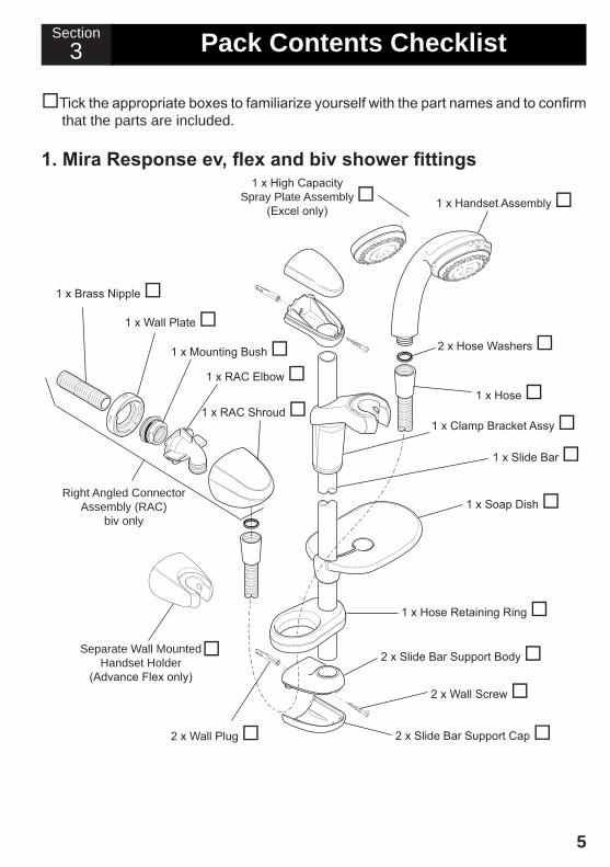
Tick the appropriate boxes to familiarize yourself with the part names and to confirm that the parts are included.
1. Mira Response ev, flex and biv shower fittings
Section3 Pack contents checklist
1 x Soap Dish
1 x Brass Nipple
1 x RAC Shroud
1 x RAC Elbow 1 x Mounting Bush
1 x Wall Plate
2 x Slide Bar Support Body
2 x Slide Bar Support Cap
1 x Slide Bar
1 x Hose
1 x Hose Retaining Ring
2 x Wall Plug
1 x Clamp Bracket Assy
2 x Hose Washers
Right Angled Connector Assembly (RAC)
biv only
2 x Wall Screw
1 x Handset Assembly 1 x High Capacity
Spray Plate Assembly(Excel only)
Separate Wall MountedHandset Holder
(Advance Flex only)
6
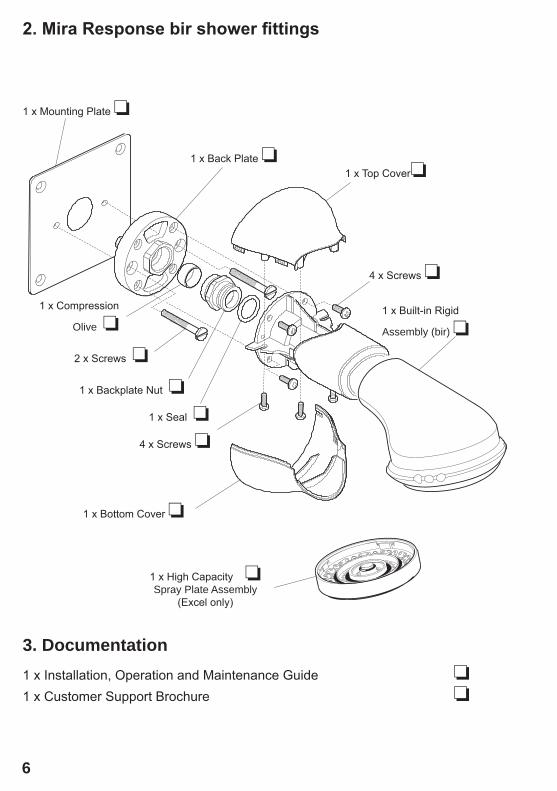
1 x Mounting Plate ❏
1 x Top Cover❏1 x Back Plate ❏
2. Mira Response bir shower fittings
3. Documentation1 x Installation, Operation and Maintenance Guide ❏1 x Customer Support Brochure ❏
1 x Built-in Rigid
Assembly (bir) ❏
4 x Screws ❏
1 x High Capacity ❏Spray Plate Assembly
(Excel only)
1 x Compression
Olive ❏
2 x Screws ❏
1 x Backplate Nut ❏
1 x Seal ❏
4 x Screws ❏
1 x Bottom Cover ❏
7
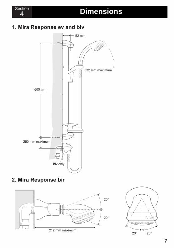
4 DimensionsSection
1. Mira Response ev and biv
2. Mira Response bir
600 mm
250 mm maximum
52 mm
332 mm maximum
biv only
212 mm maximum20° 20°
20°
20°
8
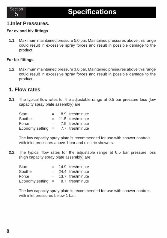
Section5 Specifications
1.inlet Pressures.For ev and biv fittings
1.1. Maximum maintained pressure 5.0 bar. Maintained pressures above this range could result in excessive spray forces and result in possible damage to the product.
For bir fittings
1.2. Maximum maintained pressure 3.0 bar. Maintained pressures above this range could result in excessive spray forces and result in possible damage to the product.
1. flow rates
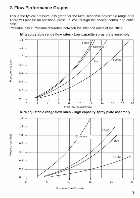
2.1. The typical flow rates for the adjustable range at 0.5 bar pressure loss (low capacity spray plate assembly) are:
Start = 8.9 litres/minute Soothe = 11.5 litres/minute Force = 7.5 litres/minute Economy setting = 7.7 litres/minute The low capacity spray plate is recommended for use with shower controls with inlet pressures above 1 bar and electric showers.
2.2. The typical flow rates for the adjustable range at 0.5 bar pressure loss (high capacity spray plate assembly) are:
Start = 14.9 litres/minute Soothe = 24.4 litres/minute Force = 13.7 litres/minute Economy setting = 8.7 litres/minute
The low capacity spray plate is recommended for use with shower controls with inlet pressures below 1 bar.
9
This is the typical pressure loss graph for the Mira Response adjustable range only. There will also be an additional pressure loss through the shower control and outlet hose.Pressure loss = Pressure difference between the inlet and outlet of the fitting.
0 2 4 6 8 10 12 14 16 18 20
0
0.2
0.4
0.6
0.8
1.0
1.2
1.4
0
0.2
0.4
0.6
0.8
1.0
1.2
1.4
0 5 252010 15
Flow rate (litres/minute)
Start Soothe
Mira adjustable range flow rates - High capacity spray plate assembly
Soothe
Flow rate (litres/minute)
Pre
ssur
e lo
ss (b
ar)
Pre
ssur
e lo
ss (b
ar)
Force
Start
Mira adjustable range flow rates - Low capacity spray plate assembly
ForceEconomy
2. flow Performance Graphs
Economy
10
Section6 installation requirements
1. PlumbingRead the section “important safety information” first.
1.1. Supply pipework MusT be flushed to clear debris before connecting the appliance.
1.2. A hose retaining ring is supplied to prevent the handset from dropping below the spill-over level of the bath or shower, which could lead to contamination from backsiphonage. The supplied hose retaining ring should meet the great majority of user requirements for shower installations with flexible outlet fittings. However, there will be occasions when the hose retaining ring will not provide a suitable solution. In these instances an outlet double checkvalve, e.g. the Mira DCV-H, must be fitted. The inclusion of the Mira DCV-H will increase the required supply pressure typically by 0.1 bar.
1.3. Avoid layouts where the shower hose will be sharply kinked. This may reduce the life of the hose.
1.4. Do not fit any form of flow control in the outlet pipework if the shower fitting is installed in conjunction with a product that requires the fitting to act as a vent (e.g. an electric shower).
1.5. Do not use excessive force when making connections.
1.6. Do not install the product in a position where it could become frozen. 1.7. For a gravity fed shower installation, the minimum pressure at the handset is
0.06 bar. To generate the minimum pressure and accommodate the pressure loss in the pipes and shower control, a head of water of 1.0 metre is required on a typical correct installation.
For a pump installation the minimum acceptable vertical distance between
the base of the cold water storage cistern and the shower head to operate the pump’s flow switches, is typically 0.6 m (600 mm).
1.8. The shower fitting is connected to the bottom outlet of the shower control or right angled connector assembly as appropriate.
1.9. When installing the shower fitting into a shower cubicle, it is best positioned to spray across the cubicle rather than towards the opening.
11
1.10. For ev and biv products the maintained water pressure at the handset should not exceed 5.0 bar. Maintained pressures above 5.0 bar at the shower head, could result in excessive spray forces and possible product damage.
1.11. For bir products the maintained water pressure at the spray should not exceed 3.0 bar. Maintained pressures above 3.0 bar at the shower head, could result in excessive spray forces and possible product damage.
1.12. Layout and sizing of pipework be such that when other services are used, pressures do not fall below the recommended minimum for that fitting as this will cause the spray pattern to collapse.
1.13. Perceived sound levels of the handset, pump (if fitted) and spray impingement, will be affected by the spray pattern selected and flow rates.
2. Spray plate assembly - selection2.1. All shower fittings have the low capacity spray plate assembly installed as
standard. The low capacity spray plate assembly is suitable for the pressures generated by a head of water between 0.6 and 5.0 Metres. For the higher pressures generated by a greater head install the high capacity spray plate assembly to allow more flow, refer to Section 9, Maintenance: 2. Spray plate assembly - removal and installation. The high capacity spray plate assembly is supplied in addition to the low capacity spray plate assembly with the Excel only. It is available upon request for other Mira shower controls.
2.2. The high capacity spray plate assembly is recommended for gas water heaters that require a higher flow rate to operate correctly.
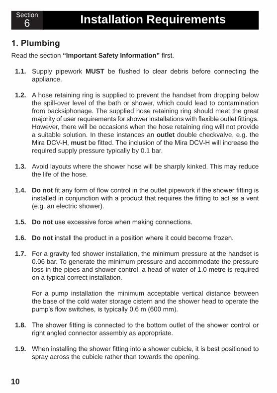
2.3. Identification - Both spray plate assemblies have an identification letter in the bottom of the centre recess in the back face. The 'L' signifies a low capacity spray plate assembly and the 'H' signifies the high capacity version.
Identification Letter
L H
12
Section7 installation
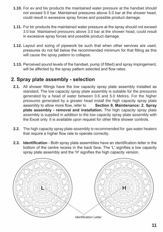
1.1. Decide on a suitable location for the slide bar avoiding buried cables and pipes. The position of the shower control and the shower fittings must provide a minimum gap of 25 mm between the spill-over level and the handset. This is to prevent backsiphonage. Alternatively the Mira outlet double check valve (DCV-H) can be fitted and is available as an accessory.
1.2. For solid walls drill two 6.0 mm
diameter holes at 600 mm centres and Insert the wall plugs.
note! Special consideration should be given to the fixing arrangements when installing on to a dry lined, stud partition, shower cubicle or laminated panel wall structures. Installers may wish to obtain alternative proprietary cavity fixing, or choose other options, however, these methods of fixing are beyond the scope of this guide.
Mira response ev and flex1. Solid, dry-lined, stud partition, shower cubicle or laminated
panel wallsRead the section “installation requirements” first.
The slide bar should be fixed to the wall to one side of the product and at a convenient height for all the family. It should be positioned so that it discharges down the centre line of the bath, or across the opening of a shower cubicle and should be directed away from the shower control.
25 mm Minimum
Spill-over level
Hose Retaining Ring
600 mm
13
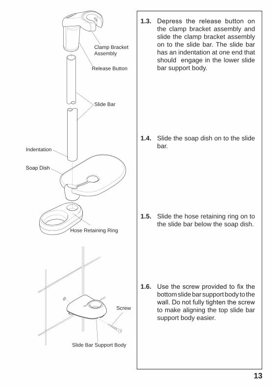
1.3. Depress the release button on the clamp bracket assembly and slide the clamp bracket assembly on to the slide bar. The slide bar has an indentation at one end that should engage in the lower slide bar support body.
1.4. Slide the soap dish on to the slide bar.
1.5. Slide the hose retaining ring on to the slide bar below the soap dish.
1.6. Use the screw provided to fix the bottom slide bar support body to the wall. Do not fully tighten the screw to make aligning the top slide bar support body easier.
Slide Bar
Soap Dish
Hose Retaining Ring
Screw
Slide Bar Support Body
Release Button
Clamp BracketAssembly
Indentation
14
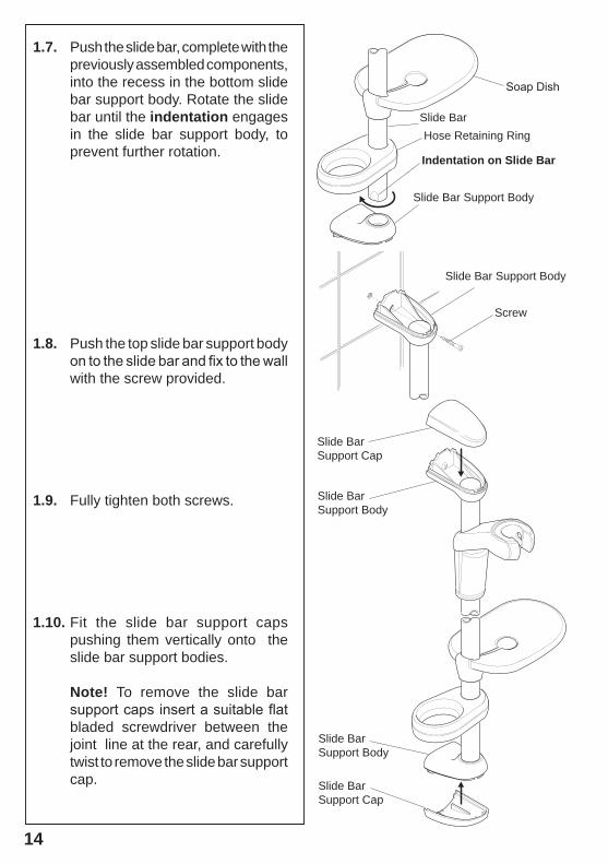
1.7. Push the slide bar, complete with the previously assembled components, into the recess in the bottom slide bar support body. Rotate the slide bar until the indentation engages in the slide bar support body, to prevent further rotation.
1.8. Push the top slide bar support body on to the slide bar and fix to the wall with the screw provided.
1.9. Fully tighten both screws.
1.10. Fit the slide bar support caps pushing them vertically onto the slide bar support bodies.
note! To remove the slide bar support caps insert a suitable flat bladed screwdriver between the joint line at the rear, and carefully twist to remove the slide bar support cap. Slide Bar
Support Cap
Slide BarSupport Body
Slide BarSupport Body
Slide BarSupport Cap
Soap Dish
Slide Bar Support Body
Screw
Slide BarHose Retaining Ring
indentation on slide bar
Slide Bar Support Body
15
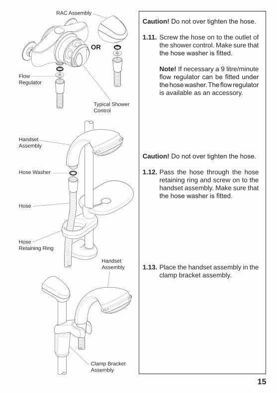
caution! Do not over tighten the hose.
1.11. Screw the hose on to the outlet of the shower control. Make sure that the hose washer is fitted.
note! If necessary a 9 litre/minute flow regulator can be fitted under the hose washer. The flow regulator is available as an accessory.
caution! Do not over tighten the hose.
1.12. Pass the hose through the hose retaining ring and screw on to the handset assembly. Make sure that the hose washer is fitted.
1.13. Place the handset assembly in the clamp bracket assembly.
HoseRetaining Ring
Hose
Hose Washer
Handset Assembly
Clamp BracketAssembly
Handset Assembly
Typical ShowerControl
RAC Assembly
FlowRegulator
or
16
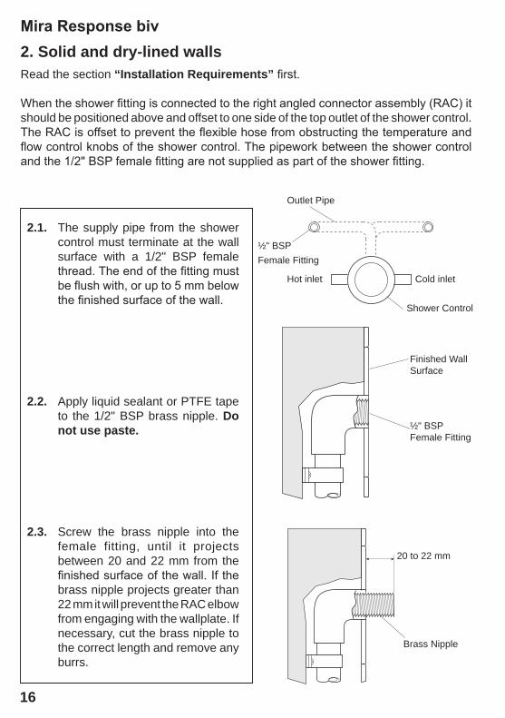
2.1. The supply pipe from the shower control must terminate at the wall surface with a 1/2" BSP female thread. The end of the fitting must be flush with, or up to 5 mm below the finished surface of the wall.
2.2. Apply liquid sealant or PTFE tape to the 1/2" BSP brass nipple. Do not use paste.
2.3. Screw the brass nipple into the female fitting, until it projects between 20 and 22 mm from the finished surface of the wall. If the brass nipple projects greater than 22 mm it will prevent the RAC elbow from engaging with the wallplate. If necessary, cut the brass nipple to the correct length and remove any burrs.
Mira Response biv2. solid and dry-lined wallsRead the section “installation requirements” first.
When the shower fitting is connected to the right angled connector assembly (RAC) it should be positioned above and offset to one side of the top outlet of the shower control. The RAC is offset to prevent the flexible hose from obstructing the temperature and flow control knobs of the shower control. The pipework between the shower control and the 1/2" BSP female fitting are not supplied as part of the shower fitting.
Hot inlet Cold inlet
Shower Control
Outlet Pipe
½" BSPFemale Fitting
Finished Wall Surface
½" BSPFemale Fitting
20 to 22 mm
Brass Nipple
17
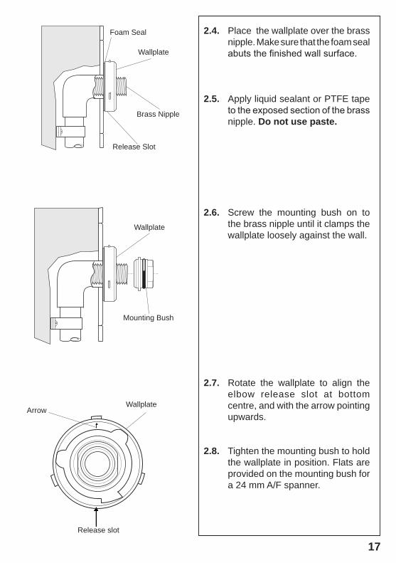
2.4. Place the wallplate over the brass nipple. Make sure that the foam seal abuts the finished wall surface.
2.5. Apply liquid sealant or PTFE tape to the exposed section of the brass nipple. Do not use paste.
2.6. Screw the mounting bush on to the brass nipple until it clamps the wallplate loosely against the wall.
2.7. Rotate the wallplate to align the elbow release slot at bottom centre, and with the arrow pointing upwards.
2.8. Tighten the mounting bush to hold the wallplate in position. Flats are provided on the mounting bush for a 24 mm A/F spanner.
Release Slot
Mounting Bush
Wallplate
Wallplate
Wallplate
Foam Seal
Brass Nipple
Release slot
Arrow
18
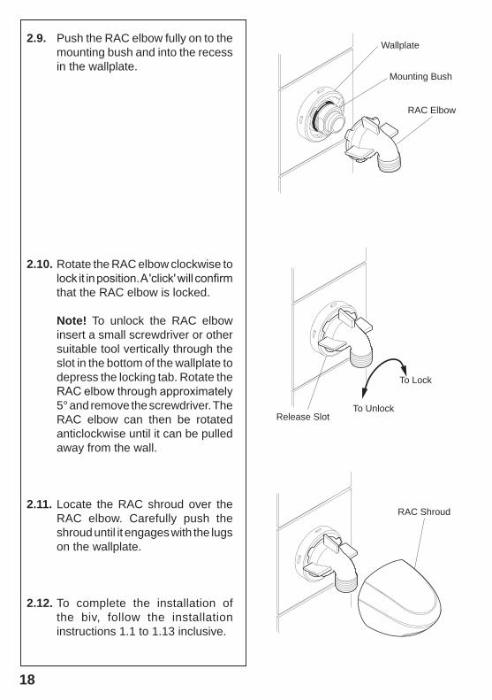
2.9. Push the RAC elbow fully on to the mounting bush and into the recess in the wallplate.
2.10. Rotate the RAC elbow clockwise to lock it in position. A 'click' will confirm that the RAC elbow is locked.
note! To unlock the RAC elbow insert a small screwdriver or other suitable tool vertically through the slot in the bottom of the wallplate to depress the locking tab. Rotate the RAC elbow through approximately 5° and remove the screwdriver. The RAC elbow can then be rotated anticlockwise until it can be pulled away from the wall.
2.11. Locate the RAC shroud over the RAC elbow. Carefully push the shroud until it engages with the lugs on the wallplate.
2.12. To complete the installation of the biv, follow the installation instructions 1.1 to 1.13 inclusive.
RAC Elbow
Mounting Bush
Wallplate
RAC Shroud
Release Slot
To Lock
To Unlock
19
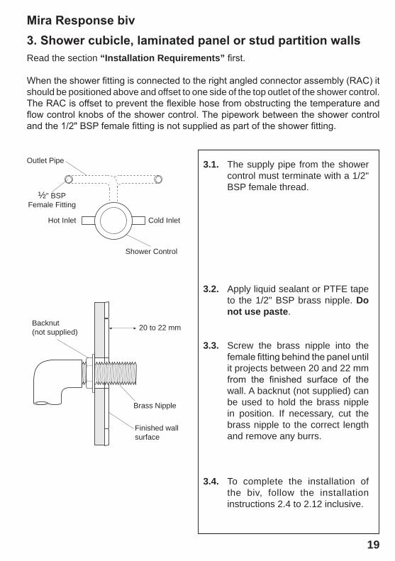
Mira Response biv3. Shower cubicle, laminated panel or stud partition wallsRead the section “installation requirements” first.
When the shower fitting is connected to the right angled connector assembly (RAC) it should be positioned above and offset to one side of the top outlet of the shower control. The RAC is offset to prevent the flexible hose from obstructing the temperature and flow control knobs of the shower control. The pipework between the shower control and the 1/2" BSP female fitting is not supplied as part of the shower fitting.
3.1. The supply pipe from the shower control must terminate with a 1/2" BSP female thread.
3.2. Apply liquid sealant or PTFE tape to the 1/2" BSP brass nipple. Do not use paste.
3.3. Screw the brass nipple into the female fitting behind the panel until it projects between 20 and 22 mm from the finished surface of the wall. A backnut (not supplied) can be used to hold the brass nipple in position. If necessary, cut the brass nipple to the correct length and remove any burrs.
3.4. To complete the installation of the biv, follow the installation instructions 2.4 to 2.12 inclusive.
Hot Inlet Cold Inlet
½" BSPFemale Fitting
Outlet Pipe
Shower Control
20 to 22 mm
Finished wall surface
Brass Nipple
Backnut(not supplied)
20
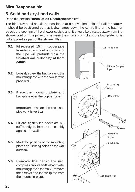
Mira Response bir5. solid and dry-lined wallsRead the section “installation requirements” first.The bir spray head should be positioned at a convenient height for all the family. It should be positioned so that it discharges down the centre line of the bath, or across the opening of the shower cubicle and it should be directed away from the shower control. The pipework between the shower control and the backplate nut is not supplied as part of the shower fitting.
Mounting Plate
Screws
Backplate
MountingPlate
Backplate
Backplate Nut
15 mm Copper Pipe
23 to 25 mm5.1. Fit recessed 15 mm copper pipe from the shower control and ensure the pipe will protrude from the finished wall surface by at least 23mm.
5.2. Loosely screw the backplate to the mounting plate with the two screws provided.
5.3. Place the mounting plate and backplate over the copper pipe.
important! Ensure the recessed pipework is vertical.
5.4. Fit and tighten the backplate nut sufficiently to hold the assembly against the wall.
5.5. Mark the position of the mounting plate and its fixing holes on the wall surface.
5.6. Remove the backplate nut, compression olive and the backplate/mounting plate assembly. Remove the screws and the wallplate from the mounting plate.
21
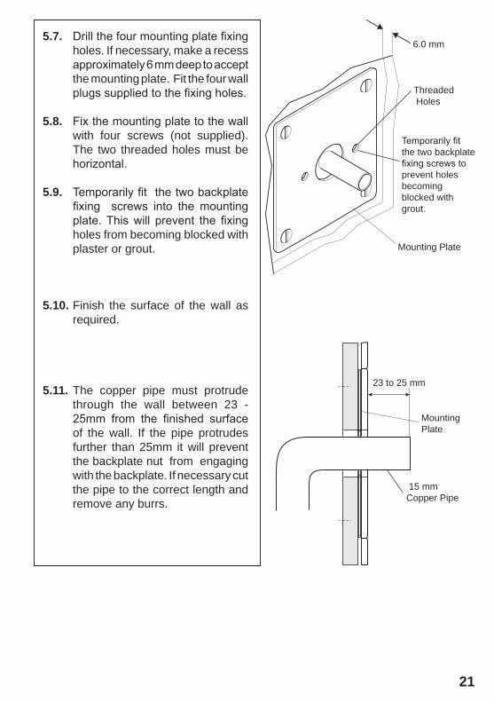
5.7. Drill the four mounting plate fixing holes. If necessary, make a recess approximately 6 mm deep to accept the mounting plate. Fit the four wall plugs supplied to the fixing holes.
5.8. Fix the mounting plate to the wall with four screws (not supplied). The two threaded holes must be horizontal.
5.9. Temporarily fit the two backplate fixing screws into the mounting plate. This will prevent the fixing holes from becoming blocked with plaster or grout.
5.10. Finish the surface of the wall as required.
5.11. The copper pipe must protrude through the wall between 23 - 25mm from the finished surface of the wall. If the pipe protrudes further than 25mm it will prevent the backplate nut from engaging with the backplate. If necessary cut the pipe to the correct length and remove any burrs.
Mounting Plate
Threaded Holes
6.0 mm
Mounting Plate
Temporarily fit the two backplate fixing screws to prevent holes becoming blocked with grout.
23 to 25 mm
15 mm Copper Pipe
22
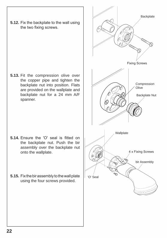
bir Assembly
Wallplate
4 x Fixing Screws
'O' Seal
5.12. Fix the backplate to the wall using the two fixing screws.
5.13. Fit the compression olive over the copper pipe and tighten the backplate nut into position. Flats are provided on the wallplate and backplate nut for a 24 mm A/F spanner.
5.14. Ensure the 'O' seal is fitted on the backplate nut. Push the bir assembly over the backplate nut onto the wallplate.
5.15. Fix the bir assembly to the wall plate using the four screws provided.
Fixing Screws
Compression Olive
Backplate
Backplate Nut
23
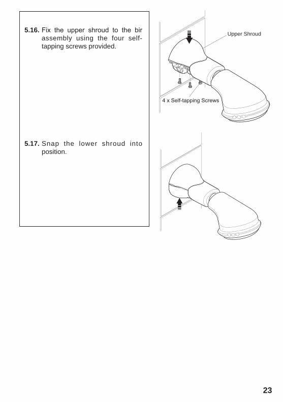
5.16. Fix the upper shroud to the bir assembly using the four self-tapping screws provided.
5.17. Snap the lower shroud into position.
Upper Shroud
4 x Self-tapping Screws
24
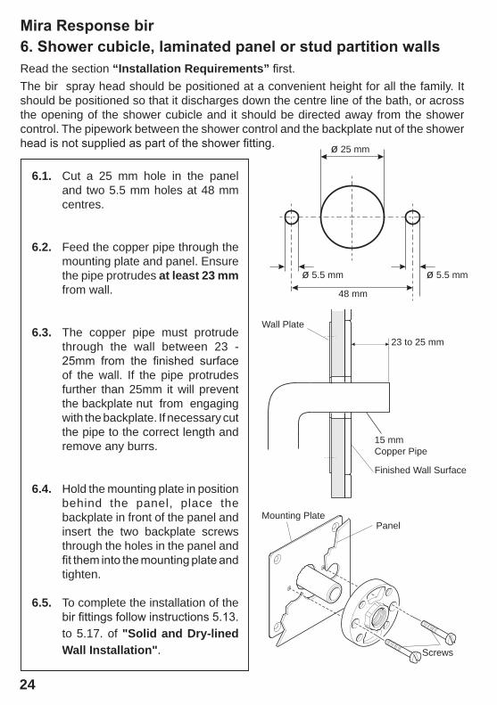
Mira Response bir6. Shower cubicle, laminated panel or stud partition wallsRead the section “installation requirements” first.The bir spray head should be positioned at a convenient height for all the family. It should be positioned so that it discharges down the centre line of the bath, or across the opening of the shower cubicle and it should be directed away from the shower control. The pipework between the shower control and the backplate nut of the shower head is not supplied as part of the shower fitting.
ø 5.5 mm
ø 25 mm
ø 5.5 mm
6.1. Cut a 25 mm hole in the panel and two 5.5 mm holes at 48 mm centres.
6.2. Feed the copper pipe through the mounting plate and panel. Ensure the pipe protrudes at least 23 mm from wall.
6.3. The copper pipe must protrude
through the wall between 23 - 25mm from the finished surface of the wall. If the pipe protrudes further than 25mm it will prevent the backplate nut from engaging with the backplate. If necessary cut the pipe to the correct length and remove any burrs.
6.4. Hold the mounting plate in position behind the panel, place the backplate in front of the panel and insert the two backplate screws through the holes in the panel and fit them into the mounting plate and tighten.
6.5. To complete the installation of the bir fittings follow instructions 5.13. to 5.17. of "solid and Dry-lined wall installation".
Mounting PlatePanel
Screws
48 mm
23 to 25 mm
Wall Plate
15 mm Copper Pipe
Finished Wall Surface
25
Section8 operation
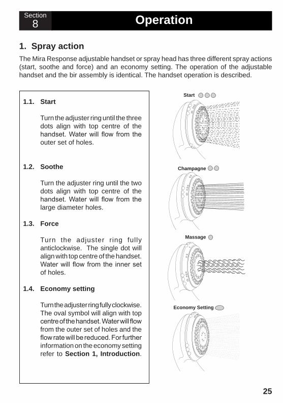
1. spray actionThe Mira Response adjustable handset or spray head has three different spray actions (start, soothe and force) and an economy setting. The operation of the adjustable handset and the bir assembly is identical. The handset operation is described.
1.1. start
Turn the adjuster ring until the three dots align with top centre of the handset. Water will flow from the outer set of holes.
1.2. soothe
Turn the adjuster ring until the two dots align with top centre of the handset. Water will flow from the large diameter holes.
1.3. force
Turn the adjuster ring fully anticlockwise. The single dot will align with top centre of the handset. Water will flow from the inner set of holes.
1.4. economy setting
Turn the adjuster ring fully clockwise. The oval symbol will align with top centre of the handset. Water will flow from the outer set of holes and the flow rate will be reduced. For further information on the economy setting refer to section 1, introduction.
Start
Champagne
Massage
Economy Setting
26
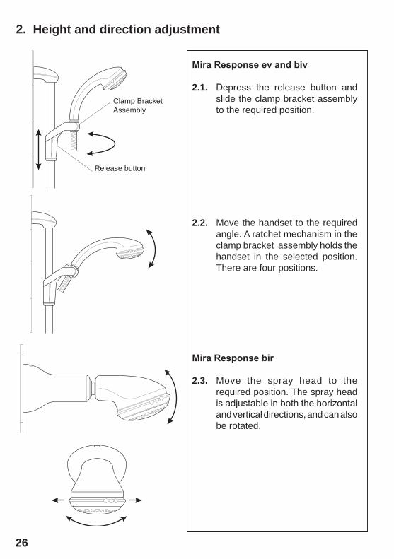
2. height and direction adjustment
Mira Response ev and biv
2.1. Depress the release button and slide the clamp bracket assembly to the required position.
2.2. Move the handset to the required angle. A ratchet mechanism in the clamp bracket assembly holds the handset in the selected position. There are four positions.
Mira Response bir
2.3. Move the spray head to the required position. The spray head is adjustable in both the horizontal and vertical directions, and can also be rotated.
Release button
Clamp BracketAssembly
27
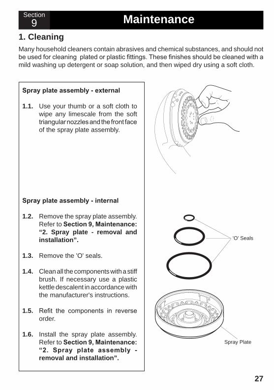
1. cleaningMany household cleaners contain abrasives and chemical substances, and should not be used for cleaning plated or plastic fittings. These finishes should be cleaned with a mild washing up detergent or soap solution, and then wiped dry using a soft cloth.
Spray plate assembly - external
1.1. Use your thumb or a soft cloth to wipe any limescale from the soft triangular nozzles and the front face of the spray plate assembly.
Spray plate assembly - internal
1.2. Remove the spray plate assembly. Refer to Section 9, Maintenance: “2. spray plate - removal and installation”.
1.3. Remove the 'O' seals.
1.4. Clean all the components with a stiff brush. If necessary use a plastic kettle descalent in accordance with the manufacturer's instructions.
1.5. Refit the components in reverse order.
1.6. Install the spray plate assembly. Refer to Section 9, Maintenance: “2. Spray plate assembly - removal and installation”.
'O' Seals
Spray Plate
Section9 Maintenance
28
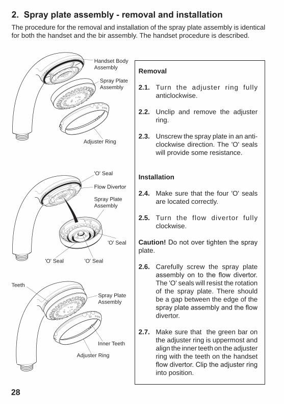
2. Spray plate assembly - removal and installationThe procedure for the removal and installation of the spray plate assembly is identical for both the handset and the bir assembly. The handset procedure is described.
removal
2.1. Turn the adjuster ring fully anticlockwise.
2.2. Unclip and remove the adjuster ring.
2.3. Unscrew the spray plate in an anti- clockwise direction. The 'O' seals will provide some resistance.
installation
2.4. Make sure that the four 'O' seals are located correctly.
2.5. Turn the flow divertor ful ly clockwise.
caution! Do not over tighten the spray plate.
2.6. Carefully screw the spray plate assembly on to the flow divertor. The 'O' seals will resist the rotation of the spray plate. There should be a gap between the edge of the spray plate assembly and the flow divertor.
2.7. Make sure that the green bar on the adjuster ring is uppermost and align the inner teeth on the adjuster ring with the teeth on the handset flow divertor. Clip the adjuster ring into position.
Handset BodyAssembly
Spray PlateAssembly
'O' Seal 'O' Seal
Adjuster Ring
Adjuster Ring
Spray PlateAssembly
Flow Divertor
'O' Seal
'O' Seal
Spray PlateAssembly
Inner Teeth
Teeth
29
Section10 fault Diagnosis
cause remedyMalfunction
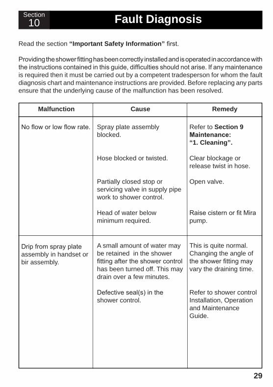
Drip from spray plate assembly in handset or bir assembly.
Read the section “important safety information” first.
Providing the shower fitting has been correctly installed and is operated in accordance with the instructions contained in this guide, difficulties should not arise. If any maintenance is required then it must be carried out by a competent tradesperson for whom the fault diagnosis chart and maintenance instructions are provided. Before replacing any parts ensure that the underlying cause of the malfunction has been resolved.
Spray plate assembly blocked.
Hose blocked or twisted.
Partially closed stop or servicing valve in supply pipe work to shower control.
Head of water below minimum required.
Refer to section 9 Maintenance: “1. cleaning”.
Clear blockage or release twist in hose.
Open valve.
Raise cistern or fit Mira pump.
No flow or low flow rate.
A small amount of water may be retained in the shower fitting after the shower control has been turned off. This may drain over a few minutes.
Defective seal(s) in the shower control.
This is quite normal. Changing the angle of the shower fitting may vary the draining time.
Refer to shower control Installation, Operation and Maintenance Guide.
30
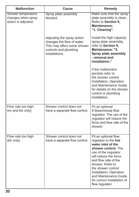
cause remedyMalfunctionShower temperature changes when spray action is adjusted.
Make sure that the spray plate assembly is clean. Refer to section 9, Maintenance: “1. cleaning”.
Install the high capacity spray plate assembly, refer to section 9, Maintenance: "2. Spray plate assembly - removal and installation."
If the malfunction persists refer to the shower control Installation, Operation and Maintenance Guide for details on the shower control or plumbing installation.
Spray plate assembly blocked.
Adjusting the spray action changes the flow of water. This may affect some shower controls and plumbing installations.
Shower control does not have a separate flow control.
Flow rate too high.(ev and biv only)
Fit an optional 9 litres/minute flow regulator. The use of the regulator will reduce the force and flow rate of the shower.
Shower control does not have a separate flow control.
Flow rate too high.(bir only)
Fit an optional flow regulator to the hot water inlet of the shower control. The use of the regulator will reduce the force and flow rate of the shower. Refer to the shower control Installation, Operation and Maintenance Guide for correct installation of flow regulator.
31
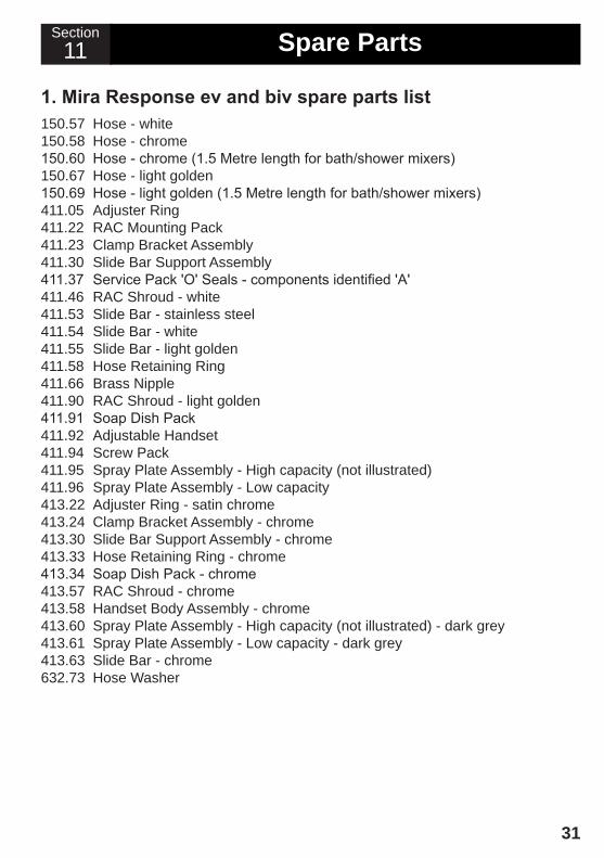
11 spare PartsSection
1. Mira Response ev and biv spare parts list 150.57 Hose - white150.58 Hose - chrome150.60 Hose - chrome (1.5 Metre length for bath/shower mixers)150.67 Hose - light golden150.69 Hose - light golden (1.5 Metre length for bath/shower mixers)411.05 Adjuster Ring411.22 RAC Mounting Pack411.23 Clamp Bracket Assembly411.30 Slide Bar Support Assembly411.37 Service Pack 'O' Seals - components identified 'A'411.46 RAC Shroud - white411.53 Slide Bar - stainless steel411.54 Slide Bar - white411.55 Slide Bar - light golden411.58 Hose Retaining Ring411.66 Brass Nipple411.90 RAC Shroud - light golden411.91 Soap Dish Pack411.92 Adjustable Handset411.94 Screw Pack411.95 Spray Plate Assembly - High capacity (not illustrated)411.96 Spray Plate Assembly - Low capacity413.22 Adjuster Ring - satin chrome413.24 Clamp Bracket Assembly - chrome413.30 Slide Bar Support Assembly - chrome413.33 Hose Retaining Ring - chrome413.34 Soap Dish Pack - chrome413.57 RAC Shroud - chrome413.58 Handset Body Assembly - chrome413.60 Spray Plate Assembly - High capacity (not illustrated) - dark grey413.61 Spray Plate Assembly - Low capacity - dark grey413.63 Slide Bar - chrome632.73 Hose Washer
32
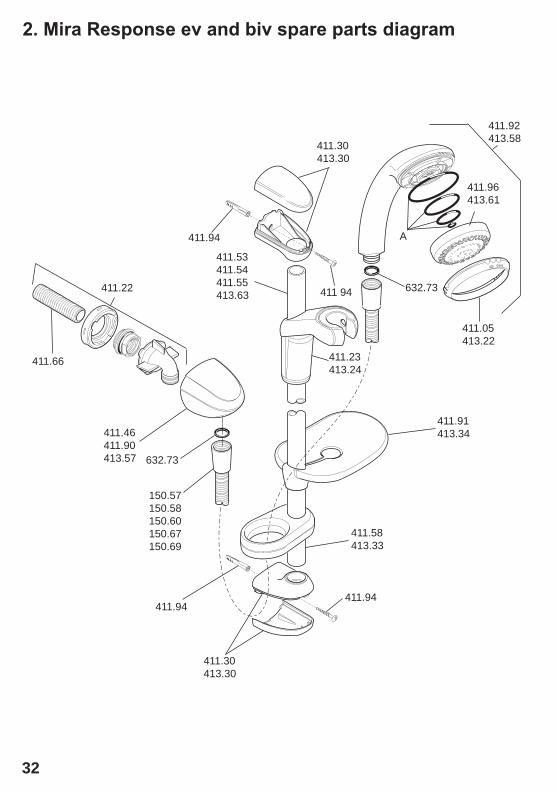
2. Mira Response ev and biv spare parts diagram
411.30413.30
411.30413.30
411.53411.54411.55413.63
411.46411.90413.57
411.66
411.05413.22
411.23413.24
632.73
150.57150.58150.60150.67150.69
411.58413.33
632.73
411.91413.34
411.94411.94
411.96413.61
A
411.22
411.92413.58
411.94
411 94
33
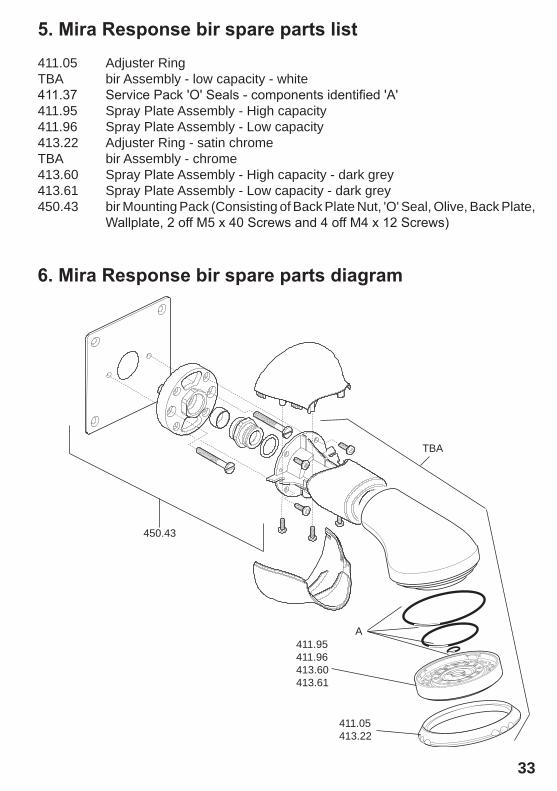
5. Mira Response bir spare parts list411.05 Adjuster RingTBA bir Assembly - low capacity - white411.37 Service Pack 'O' Seals - components identified 'A'411.95 Spray Plate Assembly - High capacity411.96 Spray Plate Assembly - Low capacity413.22 Adjuster Ring - satin chromeTBA bir Assembly - chrome413.60 Spray Plate Assembly - High capacity - dark grey413.61 Spray Plate Assembly - Low capacity - dark grey450.43 bir Mounting Pack (Consisting of Back Plate Nut, 'O' Seal, Olive, Back Plate, Wallplate, 2 off M5 x 40 Screws and 4 off M4 x 12 Screws)
6. Mira Response bir spare parts diagram
411.05413.22
A
TBA
411.95411.96413.60413.61
450.43
34
accessories
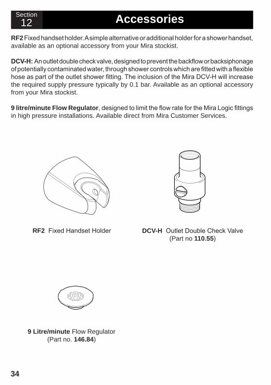
rf2 Fixed Handset Holder
9 litre/minute Flow Regulator (Part no. 146.84)
DcV-h Outlet Double Check Valve(Part no 110.55)
rf2 Fixed handset holder. A simple alternative or additional holder for a shower handset, available as an optional accessory from your Mira stockist.
DCV-H: An outlet double check valve, designed to prevent the backflow or backsiphonage of potentially contaminated water, through shower controls which are fitted with a flexible hose as part of the outlet shower fitting. The inclusion of the Mira DCV-H will increase the required supply pressure typically by 0.1 bar. Available as an optional accessory from your Mira stockist.
9 litre/minute flow regulator, designed to limit the flow rate for the Mira Logic fittings in high pressure installations. Available direct from Mira Customer Services.
12Section

35
1089165-W2-A (L86) © Kohler Mira Limited, October 2007
customer serviceGuarantee of QualityMira Showers guarantee your product against any defect in materials or workmanship for the period shown in the Guarantee Registration Document included with your shower.Alternatively, to confi rm the applicable guarantee period please contact Customer Services.To validate the guarantee, please return your completed registration card.Within the guarantee period we will resolve defects, free of charge, by repairing or replacing parts or modules as we may choose.To be free of charge, service work must only be undertaken by Mira Showers or our approved agents.Service under this guarantee does not affect the expiry date.The guarantee on any exchanged parts or product ends when the normal product guarantee period expires.Not covered by this guarantee:Damage or defects arising from incorrect installation, improper use or lack of maintenance, including build-up of limescale.Damage or defects if the product is taken apart, repaired or modifi ed by any persons not authorised by Mira Showers or our approved agents.This guarantee is in addition to your statutory and other legal rights.
What to do if something goes wrongIf when you first use your shower, it doesn’t function correctly, fi rst contact your installer to check that installation and commissioning are satisfactory and in accordance with the instructions in this manual. We are on hand to offer you or your installer any advice you may need.Should this not resolve the diffi culty, simply contact our Customer Services Team who will give every assistance and, if necessary, arrange for our service engineer to visit. If the performance of your shower declines, consult this manual to see whether simple home maintenance is required. Please call our Customer Services Team to talk the diffi culty through, request a service under guarantee if applicable, or take advantage of our comprehensive After-Sales service.As part of our quality and training programme calls may be recorded or monitored.Our Customer Services Team is comprehensively trained to provide every assistance you may need: help and advice, spare parts or a service visit.
Spare PartsWe maintain an extensive stock of spares and aim to provide support throughout the product’s expected life.Spares can be purchased from approved stockists or merchants (locations on request) or direct from Customer Services.Spares direct will normally be despatched within two working days. Payment can be made by Visa or MasterCard at the time of ordering. Should payment by cheque be preferred, a pro-forma invoice will be sent.All spares are guaranteed for 12 months from date of purchase. Spares that have been supplied directly from us can be returned within one month from date of purchase, providing that they are in good order and the packaging is unopened.Note! Returned spares will be subject to a 15% restocking charge and authorisation must be obtained before return. Please contact our Customer Services Team.Note! In the interests of safety, spares requiring exposure to mains voltages can only be sent to competent persons.
ServiceOur Service Force is available to provide a quality service at a reasonable cost. You will have the assurance of a Mira trained engineer/agent, genuine Mira spare parts and a 12 month guarantee on the repair.Payment should be made directly to the engineer/agent using Visa, MasterCard or a cheque supported by a banker’s card.
To Contact UsEngland, Scotland, Wales and Northern IrelandMira Showers Customer ServicesTelephone: 0870 241 0888, Mon to Fri 8:00 am - 5:30 pm Sat 8:30 am - 3:30 pmE-mail: [email protected]: 01242 282595By Post: Cromwell Road, Cheltenham, Gloucestershire, GL52 5EPEireModern Plant Ltd (Dublin)Telephone: 01 459 1344, Mon to Fri 9:00 am - 5:00 pmE-mail: [email protected]: Dublin 01 459 2329Post: Otter House, Naas Road, Clondalkin, Dublin 22Modern Plant (Cork)Telephone: 021 496 8755, Mon to Fri 9:00 am - 5:00 pmE-mail: [email protected]: 021 496 8607Post: Tramore Road, Cork
Mira is a registered trade mark of Kohler Mira Limited.
The company reserves the right to alter product specifi cations without notice.
www.mirashowers.com

Check out our full range of Showers Electric Showers
Digital Showers
Mixer Showers
Power Showers
Smart Showers
Shower Towers
From Top Shower Brands Mira Showers
Aqualisa Showers
Triton Showers
Gainsborough Showers
Shower Pumps can upgrade your showering experience even more Stuart Turner Shower Pumps
Salamander Shower Pumps
Grundfos Shower Pumps


