60
Engineering GREAT Solutions
Engineering GREAT Solutions
Si 830
High Flow Safety Relief Valvesdesigned acc. to API Standard 526 manufactured to ASME VIII and PED
Engineering GREATGREAT
Si 830
2
Contents 03 Features, applications, approvals and standards
04 General information
07 Type code
08 Coefficients of discharge
12 Material code
14 Trim codes
18 Sizes, pressure ranges and dimensions
18 D orifice
20 E orifice
22 F orifice
24 G orifice
26 H orifice
28 J orifice
30 K orifice
32 L orifice
34 M orifice
36 N orifice
38 P orifice
40 Q orifice
42 R orifice
44 T orifice
46 Material code orifice V and W
48 V orifice
50 W orifice
52 Air capacities USCS units
53 Air Capacities SI units
54 Saturated steam capacities USCS units
55 Saturated steam capacities SI units
56 Water capacities USCS units
57 Water capacities SI units
58 Heating jacket (option .18)
59 Design options
3
Si 8301
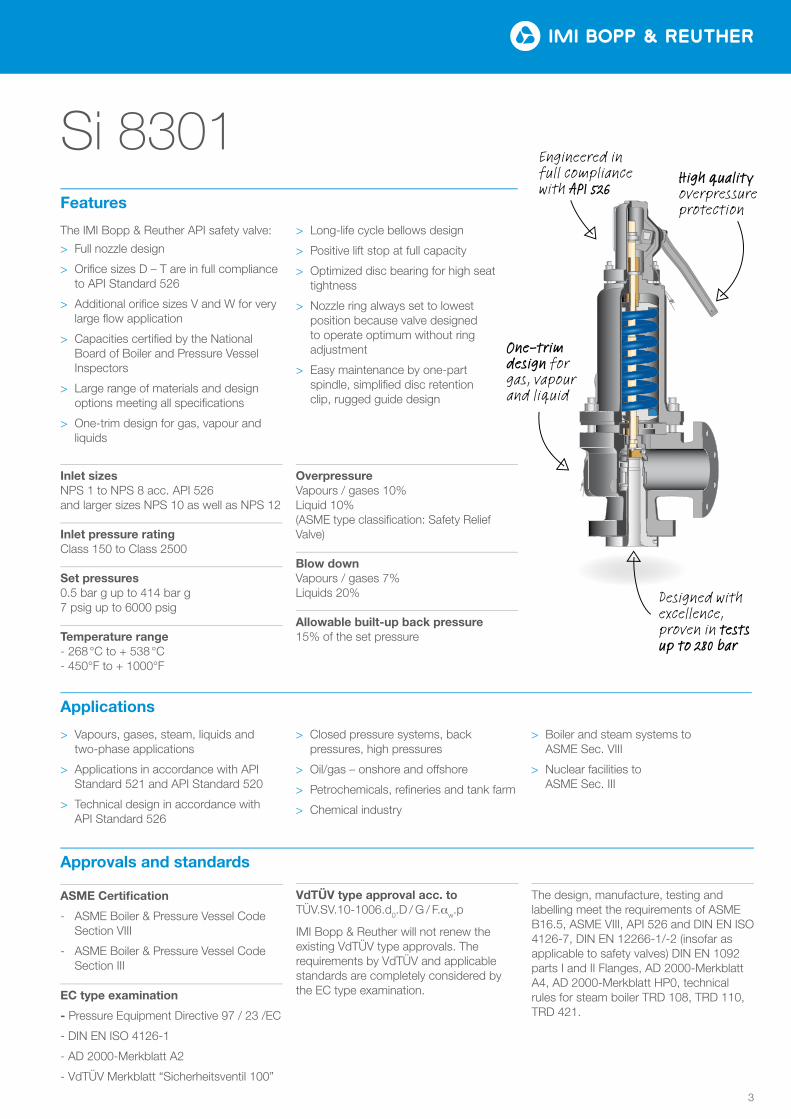
The IMI Bopp & Reuther API safety valve:
> Full nozzle design
> Orifice sizes D – T are in full compliance to API Standard 526
> Additional orifice sizes V and W for very large flow application
> Capacities certified by the National Board of Boiler and Pressure Vessel Inspectors
> Large range of materials and design options meeting all specifications
> One-trim design for gas, vapour and liquids
> Long-life cycle bellows design
> Positive lift stop at full capacity
> Optimized disc bearing for high seat tightness
> Nozzle ring always set to lowest position because valve designed to operate optimum without ring adjustment
> Easy maintenance by one-part spindle, simplified disc retention clip, rugged guide design
Features
Inlet sizesNPS 1 to NPS 8 acc. API 526and larger sizes NPS 10 as well as NPS 12
Inlet pressure ratingClass 150 to Class 2500
Set pressures0.5 bar g up to 414 bar g7 psig up to 6000 psig
Temperature range- 268 °C to + 538 °C- 450°F to + 1000°F
OverpressureVapours / gases 10%Liquid 10%(ASME type classification: Safety Relief Valve)
Blow downVapours / gases 7%Liquids 20%
Allowable built-up back pressure15% of the set pressure
> Vapours, gases, steam, liquids and two-phase applications
> Applications in accordance with API Standard 521 and API Standard 520
> Technical design in accordance with API Standard 526
> Closed pressure systems, back pressures, high pressures
> Oil/gas – onshore and o£shore
> Petrochemicals, refineries and tank farm
> Chemical industry
> Boiler and steam systems to ASME Sec. VIII
> Nuclear facilities to ASME Sec. III
Applications
Approvals and standards
ASME Certification
- ASME Boiler & Pressure Vessel Code Section VIII
- ASME Boiler & Pressure Vessel Code Section III
EC type examination
- Pressure Equipment Directive 97 / 23 /EC
- DIN EN ISO 4126-1
- AD 2000-Merkblatt A2
- VdTÜV Merkblatt “Sicherheitsventil 100”
VdTÜV type approval acc. toTÜV.SV.10-1006.d0.D / G / F.aw.p
IMI Bopp & Reuther will not renew the existing VdTÜV type approvals. The requirements by VdTÜV and applicable standards are completely considered by the EC type examination.
The design, manufacture, testing and labelling meet the requirements of ASME B16.5, ASME VIII, API 526 and DIN EN ISO 4126-7, DIN EN 12266-1/-2 (insofar as applicable to safety valves) DIN EN 1092 parts I and II Flanges, AD 2000-Merkblatt A4, AD 2000-Merkblatt HP0, technical rules for steam boiler TRD 108, TRD 110, TRD 421.
Engineered in full compliance with API 526
Designed with excellence, proven in tests up to 280 bar
One-trim design for gas, vapour and liquid
High quality overpressure protection
Si 830
4
General informationSafety valves have the function of pre- venting inadmissible overpressure in pipe systems, pressure vessels and boilers, in order to avoid danger to people, plant and the environment. They are set to a higher pressure than the operating pressure of the system to be protected.
Safety valves …
… open once the set pressure is reached.
… steady discharge the required mass flow.
… close after the pressure has dropped.
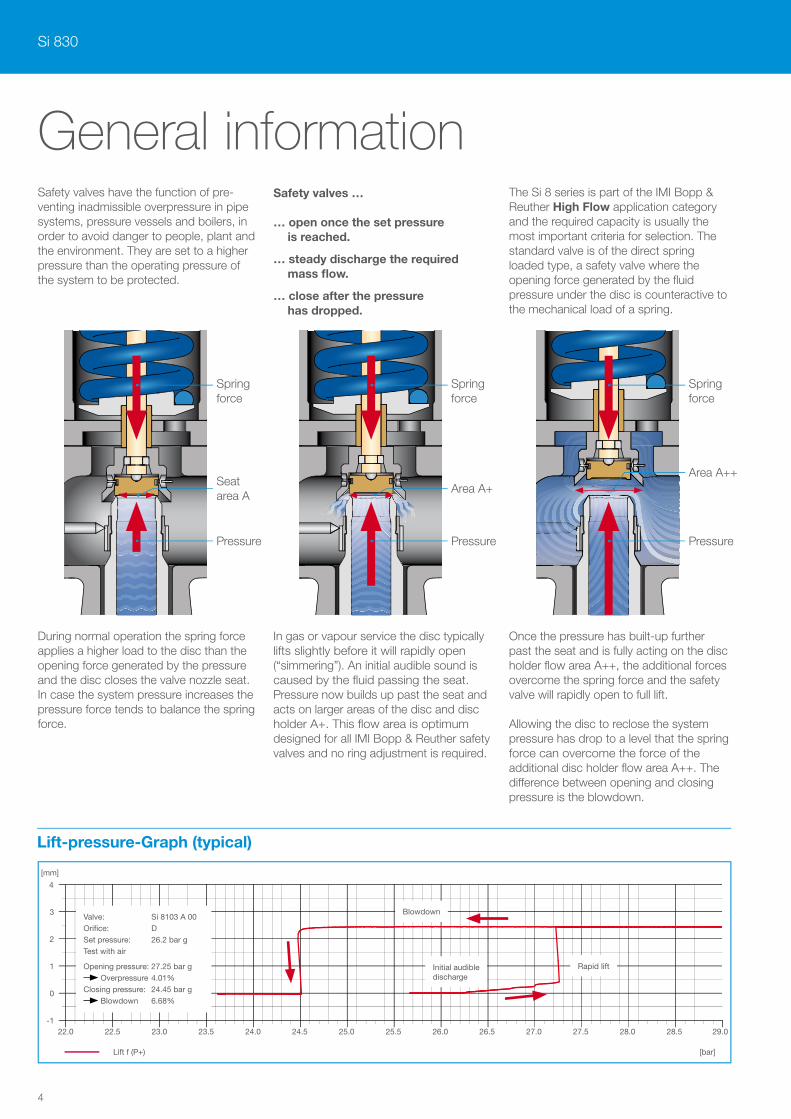
The Si 8 series is part of the IMI Bopp & Reuther High Flow application category and the required capacity is usually the most important criteria for selection. The standard valve is of the direct spring loaded type, a safety valve where the opening force generated by the fluid pressure under the disc is counteractive to the mechanical load of a spring.
During normal operation the spring force applies a higher load to the disc than the opening force generated by the pressure and the disc closes the valve nozzle seat. In case the system pressure increases the pressure force tends to balance the spring force.
In gas or vapour service the disc typically lifts slightly before it will rapidly open (“simmering”). An initial audible sound is caused by the fluid passing the seat. Pressure now builds up past the seat and acts on larger areas of the disc and disc holder A+. This flow area is optimum designed for all IMI Bopp & Reuther safety valves and no ring adjustment is required.
Once the pressure has built-up further past the seat and is fully acting on the disc holder flow area A++, the additional forces overcome the spring force and the safety valve will rapidly open to full lift. Allowing the disc to reclose the system pressure has drop to a level that the spring force can overcome the force of the additional disc holder flow area A++. The di£erence between opening and closing pressure is the blowdown.
Seat area A
Area A+Area A++
Pressure Pressure Pressure
Spring force
Spring force
Spring force
Lift-pressure-Graph (typical)
3
2
-1
1
0
4
22.0 23.0 24.0 25.0 26.0 27.0 28.022.5 23.5 24.5 25.5 26.5 27.5 28.5 29.0
[mm]
Lift f (P+) [bar]
Valve: Si 8103 A 00 Orifice: D Set pressure: 26.2 bar g Test with air
Opening pressure: 27.25 bar g Overpressure 4.01%
Closing pressure: 24.45 bar g Blowdown 6.68%
Blowdown
Rapid liftInitial audible discharge
5
General information
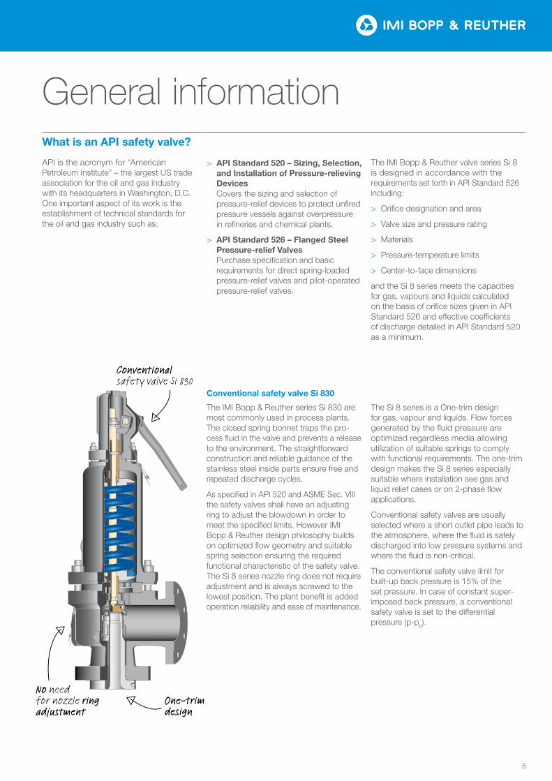
API is the acronym for “American Petroleum Institute” – the largest US trade association for the oil and gas industry with its head quarters in Washington, D.C. One important aspect of its work is the establishment of technical standards for the oil and gas industry such as:
> API Standard 520 – Sizing, Selection, and Installation of Pressure-relieving Devices
Covers the sizing and selection of pressure-relief devices to protect unfired pressure vessels against overpressure in refineries and chemical plants.
> API Standard 526 – Flanged Steel Pressure-relief Valves
Purchase specification and basic requirements for direct spring-loaded pressure-relief valves and pilot-operated pressure-relief valves.
The IMI Bopp & Reuther valve series Si 8 is designed in accordance with the require ments set forth in API Standard 526 including:
> Orifice designation and area
> Valve size and pressure rating
> Materials
> Pressure-temperature limits
> Center-to-face dimensions
and the Si 8 series meets the capacities for gas, vapours and liquids calculated on the basis of orifice sizes given in API Standard 526 and e£ective coe¬cients of discharge detailed in API Standard 520 as a minimum.
What is an API safety valve?
Conventional safety valve Si 830
The IMI Bopp & Reuther series Si 830 are most commonly used in process plants. The closed spring bonnet traps the pro-cess fluid in the valve and prevents a release to the environment. The straightforward construction and reliable guidance of the stainless steel inside parts ensure free and repeated discharge cycles.
As specified in API 520 and ASME Sec. VIII the safety valves shall have an adjusting ring to adjust the blowdown in order to meet the specified limits. However IMI Bopp & Reuther design philosophy builds on optimized flow geometry and suitable spring selection ensuring the required functional characteristic of the safety valve. The Si 8 series nozzle ring does not require adjustment and is always screwed to the lowest position. The plant benefit is added operation relia bility and ease of maintenance.
The Si 8 series is a One-trim design for gas, vapour and liquids. Flow forces generated by the fluid pressure are optimized regardless media allowing utilization of suitable springs to comply with functional requirements. The one-trim design makes the Si 8 series especially suitable where installation see gas and liquid relief cases or on 2-phase flow applications.
Conventional safety valves are usually selected where a short outlet pipe leads to the atmosphere, where the fluid is safely discharged into low pressure systems and where the fluid is non-critical.
The conventional safety valve limit for built-up back pressure is 15% of the set pressure. In case of constant super-imposed back pressure, a conventional safety valve is set to the di£erential pressure (p-pb).
Conventional safety valve Si 830
No need for nozzle ring adjustment
One-trim design
Si 830
6
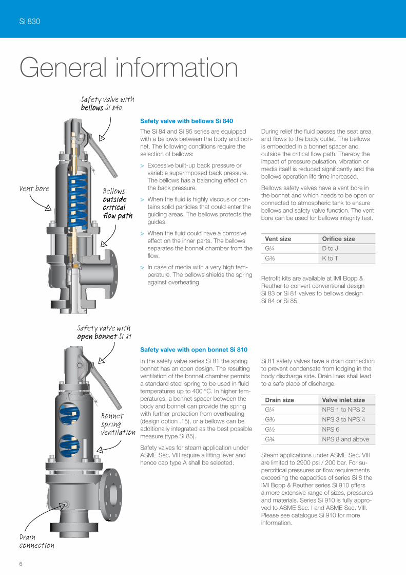
Safety valve with bellows Si 840
Vent bore Bellows outside critical flow path
Safety valve with open bonnet Si 81
Drain connection
Bonnet spring ventilation
General information
Safety valve with bellows Si 840
The Si 84 and Si 85 series are equipped with a bellows between the body and bon-net. The following conditions require the selection of bellows:
> Excessive built-up back pressure or variable superimposed back pressure. The bellows has a balancing e£ect on the back pressure.
> When the fluid is highly viscous or con-tains solid particles that could enter the guiding areas. The bellows protects the guides.
> When the fluid could have a corrosive e£ect on the inner parts. The bellows separates the bonnet chamber from the flow.
> In case of media with a very high tem-perature. The bellows shields the spring against overheating.
During relief the fluid passes the seat area and flows to the body outlet. The bellows is embedded in a bonnet spacer and outside the critical flow path. Thereby the impact of pressure pulsation, vibration or media itself is reduced significantly and the bellows operation life time increased.
Bellows safety valves have a vent bore in the bonnet and which needs to be open or connected to atmospheric tank to ensure bellows and safety valve function. The vent bore can be used for bellows integrity test.
Retrofit kits are available at IMI Bopp & Reuther to convert conventional design Si 83 or Si 81 valves to bellows design Si 84 or Si 85.
Safety valve with open bonnet Si 810
In the safety valve series Si 81 the spring bonnet has an open design. The resulting ventilation of the bonnet chamber permits a standard steel spring to be used in fluid temperatures up to 400 °C. In higher tem-peratures, a bonnet spacer between the body and bonnet can provide the spring with further protection from overheating (design option .15), or a bellows can be additionally integrated as the best possible measure (type Si 85).
Safety valves for steam application under ASME Sec. VIII require a lifting lever and hence cap type A shall be selected.
Si 81 safety valves have a drain connection to prevent condensate from lodging in the body discharge side. Drain lines shall lead to a safe place of discharge.
Steam applications under ASME Sec. VIII are limited to 2900 psi / 200 bar. For su-percritical pressures or flow requirements exceeding the capacities of series Si 8 the IMI Bopp & Reuther series Si 910 o£ers a more extensive range of sizes, pressures and materials. Series Si 910 is fully appro-ved to ASME Sec. I and ASME Sec. VIII. Please see catalogue Si 910 for more information.
Vent size Orifice size
G¼ D to J
G⅜ K to T
Drain size Valve inlet size
G¼ NPS 1 to NPS 2
G⅜ NPS 3 to NPS 4
G½ NPS 6
G¾ NPS 8 and above
7
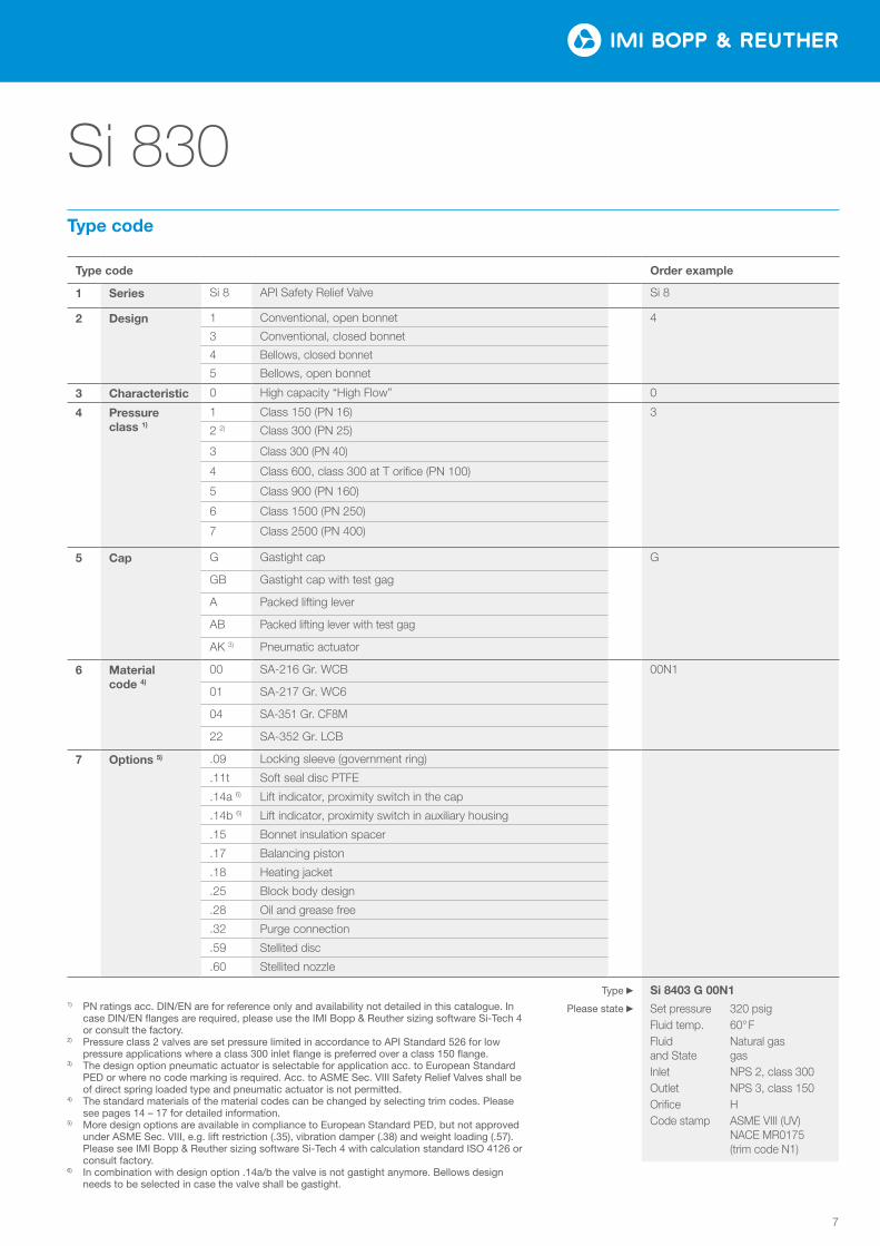
Type code Order example
1 Series Si 8 API Safety Relief Valve Si 8
2 Design 1 Conventional, open bonnet 4
3 Conventional, closed bonnet
4 Bellows, closed bonnet
5 Bellows, open bonnet
3 Characteristic 0 High capacity “High Flow” 0
4 Pressure class 1)
1 Class 150 (PN 16) 3
2 2) Class 300 (PN 25)
3 Class 300 (PN 40)
4 Class 600, class 300 at T orifice (PN 100)
5 Class 900 (PN 160)
6 Class 1500 (PN 250)
7 Class 2500 (PN 400)
5 Cap G Gastight cap G
GB Gastight cap with test gag
A Packed lifting lever
AB Packed lifting lever with test gag
AK 3) Pneumatic actuator
6 Material code 4)
00 SA-216 Gr. WCB 00N1
01 SA-217 Gr. WC6
04 SA-351 Gr. CF8M
22 SA-352 Gr. LCB
7 Options 5) .09 Locking sleeve (government ring)
.11t Soft seal disc PTFE
.14a 6) Lift indicator, proximity switch in the cap
.14b 6) Lift indicator, proximity switch in auxiliary housing
.15 Bonnet insulation spacer
.17 Balancing piston
.18 Heating jacket
.25 Block body design
.28 Oil and grease free
.32 Purge connection
.59 Stellited disc
.60 Stellited nozzle
Si 8403 G 00N1
Set pressure 320 psigFluid temp. 60°FFluid Natural gas and State gas Inlet NPS 2, class 300Outlet NPS 3, class 150Orifice HCode stamp ASME VIII (UV) NACE MR0175 (trim code N1)
Si 830Type code
1) PN ratings acc. DIN/EN are for reference only and availability not detailed in this catalogue. In case DIN/EN flanges are required, please use the IMI Bopp & Reuther sizing software Si-Tech 4 or consult the factory.
2) Pressure class 2 valves are set pressure limited in accordance to API Standard 526 for low pressure applications where a class 300 inlet flange is preferred over a class 150 flange.
3) The design option pneumatic actuator is selectable for application acc. to European Standard PED or where no code marking is required. Acc. to ASME Sec. VIII Safety Relief Valves shall be of direct spring loaded type and pneumatic actuator is not permitted.
4) The standard materials of the material codes can be changed by selecting trim codes. Please see pages 14 – 17 for detailed information.
5) More design options are available in compliance to European Standard PED, but not approved under ASME Sec. VIII, e.g. lift restriction (.35), vibration damper (.38) and weight loading (.57). Please see IMI Bopp & Reuther sizing software Si-Tech 4 with calculation standard ISO 4126 or consult factory.
6) In combination with design option .14a/b the valve is not gastight anymore. Bellows design needs to be selected in case the valve shall be gastight.
Type
Please state
Si 830
8
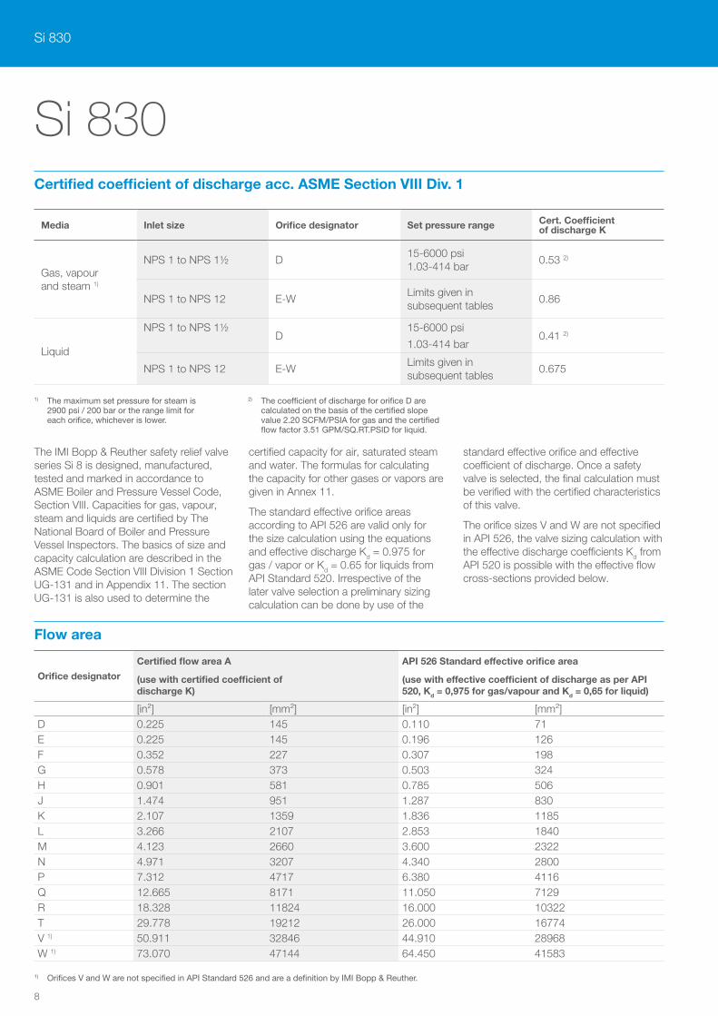
The IMI Bopp & Reuther safety relief valve series Si 8 is designed, manufactured, tested and marked in accordance to ASME Boiler and Pressure Vessel Code, Section VIII. Capacities for gas, vapour, steam and liquids are certified by The National Board of Boiler and Pressure Vessel Inspectors. The basics of size and capacity calculation are described in the ASME Code Section VIII Division 1 Section UG-131 and in Appendix 11. The section UG-131 is also used to determine the
certified capacity for air, saturated steam and water. The formulas for calculating the capacity for other gases or vapors are given in Annex 11.
The standard effective orifice areas according to API 526 are valid only for the size calculation using the equations and effective discharge Kd = 0.975 for gas / vapor or Kd = 0.65 for liquids from API Standard 520. Irrespective of the later valve selection a preliminary sizing calculation can be done by use of the
standard effective orifice and effective coefficient of discharge. Once a safety valve is selected, the final calculation must be verified with the certified characteristics of this valve.
The orifice sizes V and W are not specified in API 526, the valve sizing calculation with the effective discharge coefficients Kd from API 520 is possible with the effective flow cross-sections provided below.
1) The maximum set pressure for steam is 2900 psi / 200 bar or the range limit for each orifice, whichever is lower.
2) The coefficient of discharge for orifice D are calculated on the basis of the certified slope value 2.20 SCFM/PSIA for gas and the certified flow factor 3.51 GPM/SQ.RT.PSID for liquid.
1) Orifices V and W are not specified in API Standard 526 and are a definition by IMI Bopp & Reuther.
Media Inlet size Orifice designator Set pressure range Cert. Coefficient of discharge K
Gas, vapour and steam 1)
NPS 1 to NPS 1½ D15-6000 psi 1.03-414 bar
0.53 2)
NPS 1 to NPS 12 E-WLimits given in subsequent tables
0.86
Liquid
NPS 1 to NPS 1½D
15-6000 psi
1.03-414 bar0.41 2)
NPS 1 to NPS 12 E-WLimits given in subsequent tables
0.675
Certified coefficient of discharge acc. ASME Section VIII Div. 1
Flow area
Si 830
Orifice designator
Certified flow area A
(use with certified coefficient of discharge K)
API 526 Standard effective orifice area
(use with effective coefficient of discharge as per API 520, Kd = 0,975 for gas/vapour and Kd = 0,65 for liquid)
[in²] [mm²] [in²] [mm²]D 0.225 145 0.110 71E 0.225 145 0.196 126F 0.352 227 0.307 198G 0.578 373 0.503 324H 0.901 581 0.785 506J 1.474 951 1.287 830K 2.107 1359 1.836 1185L 3.266 2107 2.853 1840M 4.123 2660 3.600 2322N 4.971 3207 4.340 2800P 7.312 4717 6.380 4116Q 12.665 8171 11.050 7129R 18.328 11824 16.000 10322T 29.778 19212 26.000 16774V 1) 50.911 32846 44.910 28968W 1) 73.070 47144 64.450 41583
9
Si 830
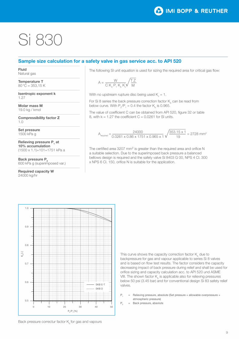
Fluid Natural gas
Temperature T80 °C = 353,15 K
Isentropic exponent k1.27
Molar mass M19.0 kg / kmol
Compressibility factor Z1.0
Set pressure1500 kPa g
Relieving pressure P1 at 10% accumulation(1500 x 1.1)+101=1751 kPa a
Back pressure P2600 kPa g (superimposed var.)
Required capacity W24000 kg/hr
The following SI unit equation is used for sizing the required area for critical gas flow:
With no upstream rupture disc being used Kc = 1.
For Si 8 series the back pressure correction factor Kb can be read from below curve. With P2/P1 = 0.4 the factor Kb is 0.965.
The value of coe¬cient C can be obtained from API 520, figure 32 or table 8, with k = 1.27 the coe¬cient C = 0.0261 for SI units.
The certified area 3207 mm² is greater than the required area and orifice N a suitable selection. Due to the superimposed back pressure a balanced bellows design is required and the safety valve Si 8403 G 00, NPS 4 Cl. 300 x NPS 6 Cl. 150, orifice N is suitable for the application.
Sample size calculation for a safety valve in gas service acc. to API 520
This curve shows the capacity correction factor Kb due to backpressure for gas and vapour applicable to series Si 8 valves and is based on flow test results. The factor considers the capacity decreasing impact of back pressure during relief and shall be used for orifice sizing and capacity calculation acc. to API 520 und ASME VIII. The shown factor Kb is applicable also for relieving pressures below 50 psi (3.45 bar) and for conventional design Si 83 safety relief valves.
P1 = Relieving pressure, absolute (Set pressure + allowable overpressure + atmospheric pressure)P2 = Back pressure, absolute
Back pressure correctur factor Kb for gas and vapours
0.5
0.6
0.7
0.8
0.9
1.0
0 10 20 30 40 50
K b [−
]
pb/p0 [%]
Si 8
SKB E−T SKB D
0 5040302010
P2/P1 [%]
0.9
1.0
0.6
0.8
0.7
0.5
Kb
[–]
SKB E-T
SKB D
0.5
0.6
0.7
0.8
0.9
1.0
0 10 20 30 40 50
K b [−
]
pb/p0 [%]
Si 8
SKB E−T SKB D
0.5
0.6
0.7
0.8
0.9
1.0
0 10 20 30 40 50
K b [−
]
pb/p0 [%]
Si 8
SKB E−T SKB D
T Z M
A = WC Kd P1 Kb Kc
353.15 x 1 19
Arequired = = 2728 mm2240000.0261 x 0.86 x 1751 x 0.965 x 1
Si 830
10
0.0
0.1
0.2
0.3
0.4
0.5
0.6
0.7
0.8
0.9
0.00 0.05 0.10 0.15 0.20 0.25 0.30 0.35 0.40
αw
[−]
h/d0 [−]
0.0
0.1
0.2
0.3
0.4
0.5
0.6
0.7
0.8
0.9
0.00 0.05 0.10 0.15 0.20 0.25 0.30 0.35 0.40
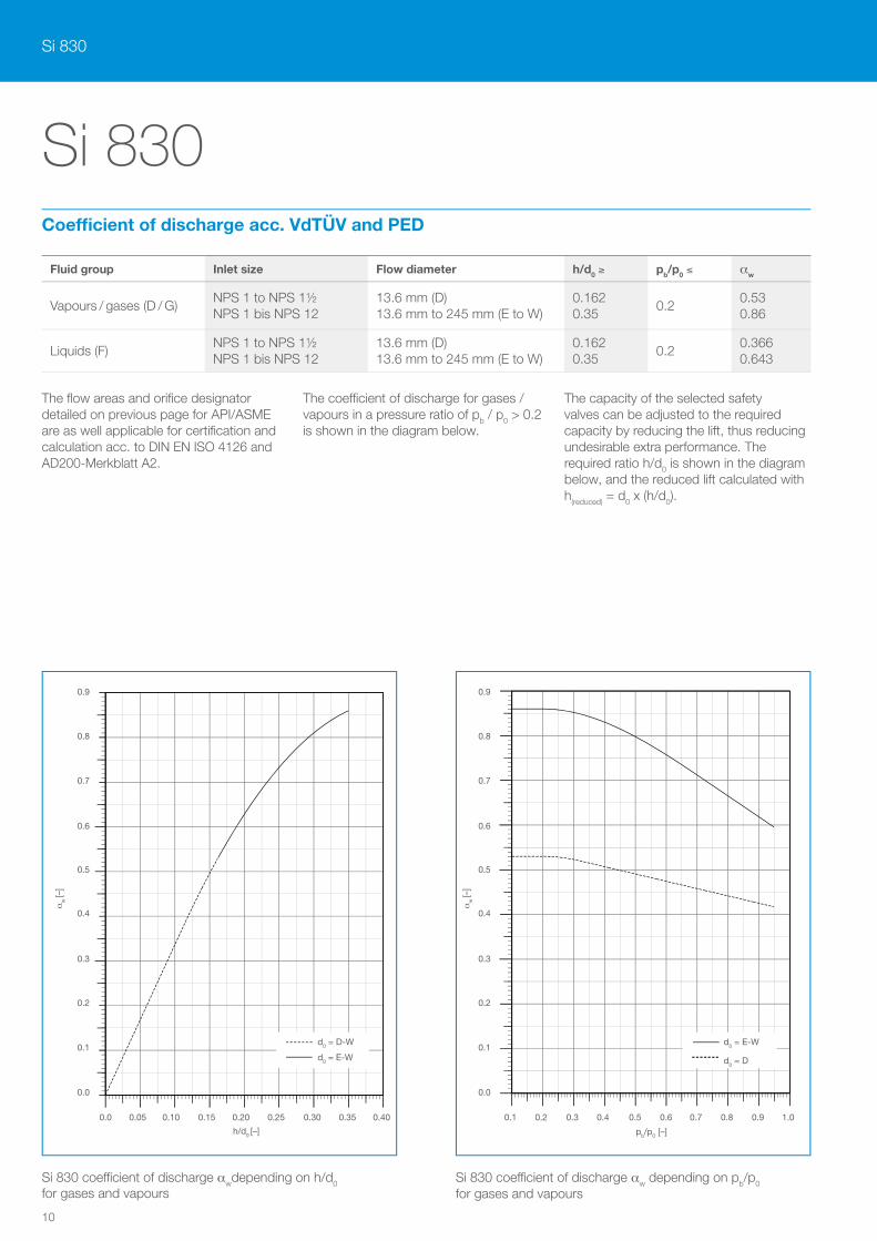
Si 830Coefficient of discharge acc. VdTÜV and PED
Fluid group Inlet size Flow diameter h/d0 ≥ pb/p0 ≤ aw
Vapours / gases (D / G)NPS 1 to NPS 1½ NPS 1 bis NPS 12
13.6 mm (D) 13.6 mm to 245 mm (E to W)
0.162 0.35
0.20.53 0.86
Liquids (F)NPS 1 to NPS 1½ NPS 1 bis NPS 12
13.6 mm (D) 13.6 mm to 245 mm (E to W)
0.162 0.35
0.20.366 0.643
The flow areas and orifice designator detailed on previous page for API/ASME are as well applicable for certification and calculation acc. to DIN EN ISO 4126 and AD200-Merkblatt A2.
The coe¬cient of discharge for gases / vapours in a pressure ratio of pb / p0 > 0.2 is shown in the diagram below.
The capacity of the selected safety valves can be adjusted to the required capacity by reducing the lift, thus reducing undesirable extra performance. The required ratio h/d0 is shown in the diagram below, and the reduced lift calculated with h(reduced) = d0 x (h/d0).
0.0
0.1
0.2
0.3
0.4
0.5
0.6
0.7
0.8
0.9
0.1 0.2 0.3 0.4 0.5 0.6 0.7 0.8 0.9 1.0
αW
[−]
pa/p0 [−]
0.0
0.1
0.2
0.3
0.4
0.5
0.6
0.7
0.8
0.9
0.1 0.2 0.3 0.4 0.5 0.6 0.7 0.8 0.9 1.0
0.90.9
0.80.8
0.70.7
0.60.6
0.50.5
0.40.4
0.30.3
0.20.2
0.10.1
0.00.0
aw
[–]
aw
[–]
0.1 0.2 0.3 0.4 0.5 0.6 0.7 0.8 0.9 1.0
pb/p0 [–]
d0 = E-Wd0 = D-W
0.050.0 0.10 0.15 0.20 0.25 0.30 0.35 0.40
h/d0 [–]
Si 830 coe¬cient of discharge awdepending on h/d0
for gases and vapoursSi 830 coe¬cient of discharge aw depending on pb/p0 for gases and vapours
d0 = Dd0 = E-W
11
Si 830
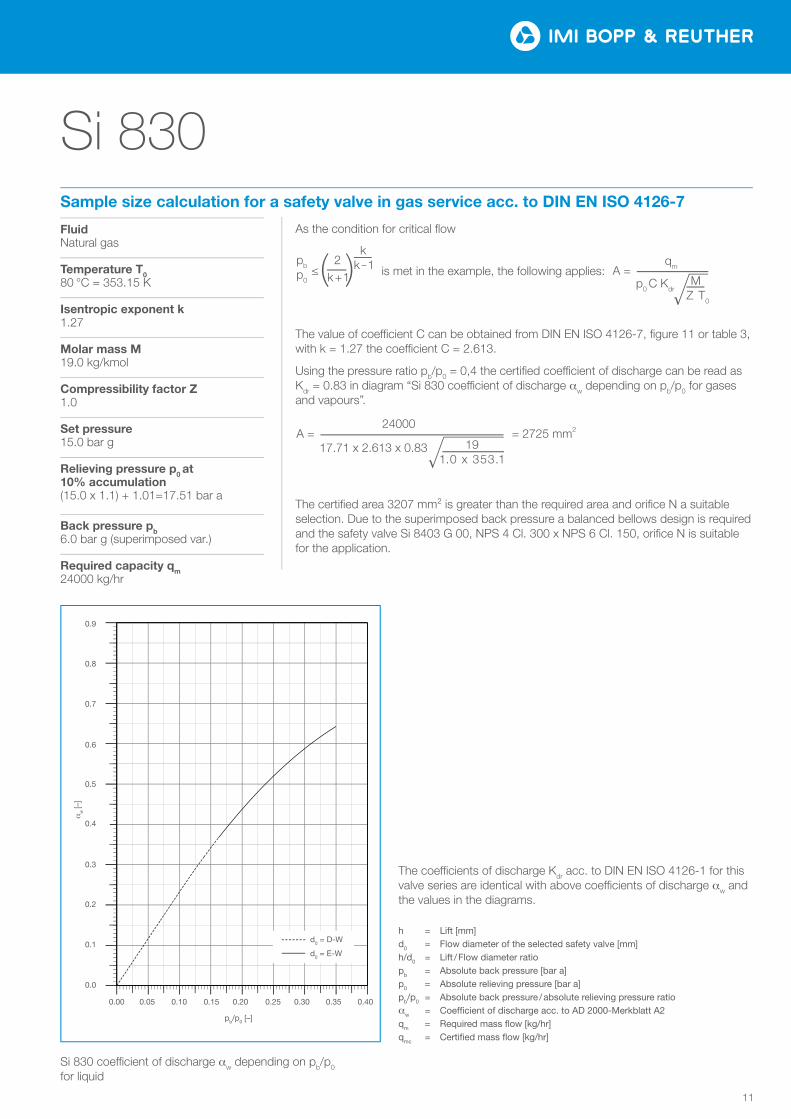
Si 830 coe¬cient of discharge aw depending on pb/p0 for liquid
0.0
0.1
0.2
0.3
0.4
0.5
0.6
0.7
0.8
0.9
0.00 0.05 0.10 0.15 0.20 0.25 0.30 0.35 0.40
αw
[−]
h/d0 [−]
0.0
0.1
0.2
0.3
0.4
0.5
0.6
0.7
0.8
0.9
0.00 0.05 0.10 0.15 0.20 0.25 0.30 0.35 0.400.00 0.05 0.10 0.15 0.20 0.25 0.30 0.35 0.40
pb/p0 [–]
0.9
0.8
0.7
0.6
0.3
0.2
0.1
0.0
aw
[–]
0.4
0.5
The coe¬cients of discharge Kdr acc. to DIN EN ISO 4126-1 for this valve series are identical with above coe¬cients of discharge aw and the values in the diagrams.
h = Lift [mm]d0 = Flow diameter of the selected safety valve [mm]h/d0 = Lift / Flow diameter ratiopb = Absolute back pressure [bar a]p0 = Absolute relieving pressure [bar a]pb/p0 = Absolute back pressure / absolute relieving pressure ratioaw = Coefficient of discharge acc. to AD 2000-Merkblatt A2qm = Required mass flow [kg/hr]qmc = Certified mass flow [kg/hr]
d0 = D-W
d0 = E-W
Fluid Natural gas
Temperature T080 °C = 353.15 K
Isentropic exponent k1.27
Molar mass M19.0 kg/kmol
Compressibility factor Z1.0
Set pressure15.0 bar g
Relieving pressure p0 at 10% accumulation(15.0 x 1.1) + 1.01=17.51 bar a
Back pressure pb6.0 bar g (superimposed var.)
Required capacity qm24000 kg/hr
As the condition for critical flow
The value of coe¬cient C can be obtained from DIN EN ISO 4126-7, figure 11 or table 3, with k = 1.27 the coe¬cient C = 2.613.
Using the pressure ratio pb/p0 = 0,4 the certified coe¬cient of discharge can be read as Kdr = 0.83 in diagram “Si 830 coe¬cient of discharge aw depending on pb/p0 for gases and vapours”.
The certified area 3207 mm² is greater than the required area and orifice N a suitable selection. Due to the superimposed back pressure a balanced bellows design is required and the safety valve Si 8403 G 00, NPS 4 Cl. 300 x NPS 6 Cl. 150, orifice N is suitable for the application.
pb ≤ 2
p0 k+1
k k-1 A =
qm
p0 C Kdr
M Z T0
A = 24000
= 2725 mm2
17.71 x 2.613 x 0.83 191.0 x 353.1
is met in the example, the following applies:
Sample size calculation for a safety valve in gas service acc. to DIN EN ISO 4126-7
Si 830
12
565557
58
24
28
25
27
29
22
26
23
21
1911
12
10
89
756
1
23
4
15
30
18
13
16
17
14
20
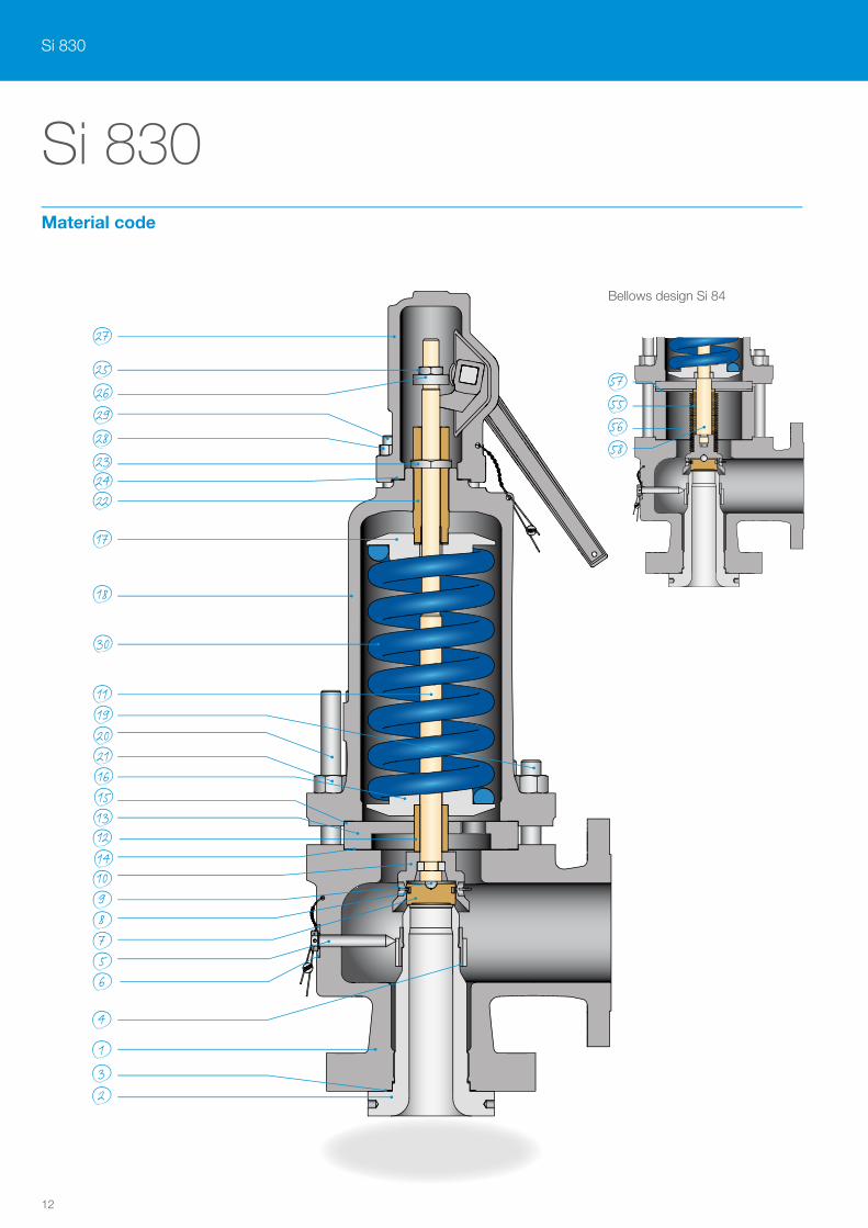
Si 830Material code
Bellows design Si 84
13
Si 830
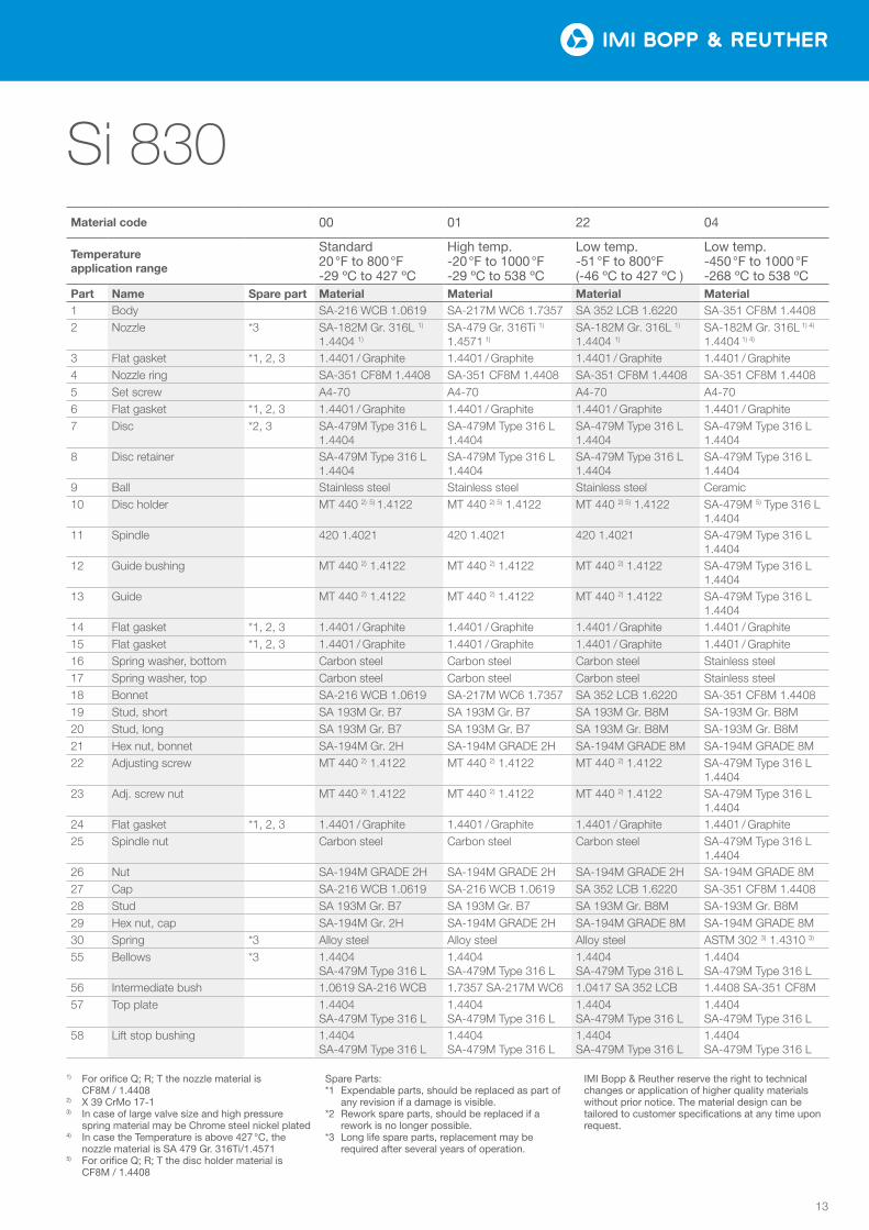
1) For orifice Q; R; T the nozzle material is CF8M / 1.4408
2) X 39 CrMo 17-13) In case of large valve size and high pressure
spring material may be Chrome steel nickel plated4) In case the Temperature is above 427 °C, the
nozzle material is SA 479 Gr. 316Ti/1.45715) For orifice Q; R; T the disc holder material is
CF8M / 1.4408
Spare Parts:*1 Expendable parts, should be replaced as part of
any revision if a damage is visible.*2 Rework spare parts, should be replaced if a
rework is no longer possible.*3 Long life spare parts, replacement may be
required after several years of operation.
IMI Bopp & Reuther reserve the right to technical changes or application of higher quality materials without prior notice. The material design can be tailored to customer specifications at any time upon request.
Material code 00 01 22 04
Temperature application range
Standard 20 °F to 800 °F -29 ºC to 427 ºC
High temp. -20 °F to 1000 °F -29 ºC to 538 ºC
Low temp. -51 °F to 800°F (-46 ºC to 427 ºC )
Low temp. -450 °F to 1000 °F -268 ºC to 538 ºC
Part Name Spare part Material Material Material Material1 Body SA-216 WCB 1.0619 SA-217M WC6 1.7357 SA 352 LCB 1.6220 SA-351 CF8M 1.44082 Nozzle *3 SA-182M Gr. 316L 1)
1.4404 1)SA-479 Gr. 316Ti 1)
1.4571 1) SA-182M Gr. 316L 1)
1.4404 1)SA-182M Gr. 316L 1) 4)
1.4404 1) 4)
3 Flat gasket *1, 2, 3 1.4401 / Graphite 1.4401 / Graphite 1.4401 / Graphite 1.4401 / Graphite4 Nozzle ring SA-351 CF8M 1.4408 SA-351 CF8M 1.4408 SA-351 CF8M 1.4408 SA-351 CF8M 1.44085 Set screw A4-70 A4-70 A4-70 A4-706 Flat gasket *1, 2, 3 1.4401 / Graphite 1.4401 / Graphite 1.4401 / Graphite 1.4401 / Graphite7 Disc *2, 3 SA-479M Type 316 L
1.4404SA-479M Type 316 L 1.4404
SA-479M Type 316 L 1.4404
SA-479M Type 316 L 1.4404
8 Disc retainer SA-479M Type 316 L 1.4404
SA-479M Type 316 L 1.4404
SA-479M Type 316 L 1.4404
SA-479M Type 316 L 1.4404
9 Ball Stainless steel Stainless steel Stainless steel Ceramic10 Disc holder MT 440 2) 5) 1.4122 MT 440 2) 5) 1.4122 MT 440 2) 5) 1.4122 SA-479M 5) Type 316 L
1.440411 Spindle 420 1.4021 420 1.4021 420 1.4021 SA-479M Type 316 L
1.440412 Guide bushing MT 440 2) 1.4122 MT 440 2) 1.4122 MT 440 2) 1.4122 SA-479M Type 316 L
1.440413 Guide MT 440 2) 1.4122 MT 440 2) 1.4122 MT 440 2) 1.4122 SA-479M Type 316 L
1.440414 Flat gasket *1, 2, 3 1.4401 / Graphite 1.4401 / Graphite 1.4401 / Graphite 1.4401 / Graphite15 Flat gasket *1, 2, 3 1.4401 / Graphite 1.4401 / Graphite 1.4401 / Graphite 1.4401 / Graphite16 Spring washer, bottom Carbon steel Carbon steel Carbon steel Stainless steel17 Spring washer, top Carbon steel Carbon steel Carbon steel Stainless steel18 Bonnet SA-216 WCB 1.0619 SA-217M WC6 1.7357 SA 352 LCB 1.6220 SA-351 CF8M 1.440819 Stud, short SA 193M Gr. B7 SA 193M Gr. B7 SA 193M Gr. B8M SA-193M Gr. B8M20 Stud, long SA 193M Gr. B7 SA 193M Gr. B7 SA 193M Gr. B8M SA-193M Gr. B8M21 Hex nut, bonnet SA-194M Gr. 2H SA-194M GRADE 2H SA-194M GRADE 8M SA-194M GRADE 8M22 Adjusting screw MT 440 2) 1.4122 MT 440 2) 1.4122 MT 440 2) 1.4122 SA-479M Type 316 L
1.440423 Adj. screw nut MT 440 2) 1.4122 MT 440 2) 1.4122 MT 440 2) 1.4122 SA-479M Type 316 L
1.440424 Flat gasket *1, 2, 3 1.4401 / Graphite 1.4401 / Graphite 1.4401 / Graphite 1.4401 / Graphite25 Spindle nut Carbon steel Carbon steel Carbon steel SA-479M Type 316 L
1.440426 Nut SA-194M GRADE 2H SA-194M GRADE 2H SA-194M GRADE 2H SA-194M GRADE 8M27 Cap SA-216 WCB 1.0619 SA-216 WCB 1.0619 SA 352 LCB 1.6220 SA-351 CF8M 1.440828 Stud SA 193M Gr. B7 SA 193M Gr. B7 SA 193M Gr. B8M SA-193M Gr. B8M29 Hex nut, cap SA-194M Gr. 2H SA-194M GRADE 2H SA-194M GRADE 8M SA-194M GRADE 8M30 Spring *3 Alloy steel Alloy steel Alloy steel ASTM 302 3) 1.4310 3)
55 Bellows *3 1.4404 SA-479M Type 316 L
1.4404 SA-479M Type 316 L
1.4404 SA-479M Type 316 L
1.4404 SA-479M Type 316 L
56 Intermediate bush 1.0619 SA-216 WCB 1.7357 SA-217M WC6 1.0417 SA 352 LCB 1.4408 SA-351 CF8M57 Top plate 1.4404
SA-479M Type 316 L1.4404 SA-479M Type 316 L
1.4404 SA-479M Type 316 L
1.4404 SA-479M Type 316 L
58 Lift stop bushing 1.4404 SA-479M Type 316 L
1.4404 SA-479M Type 316 L
1.4404 SA-479M Type 316 L
1.4404 SA-479M Type 316 L
Si 830
14
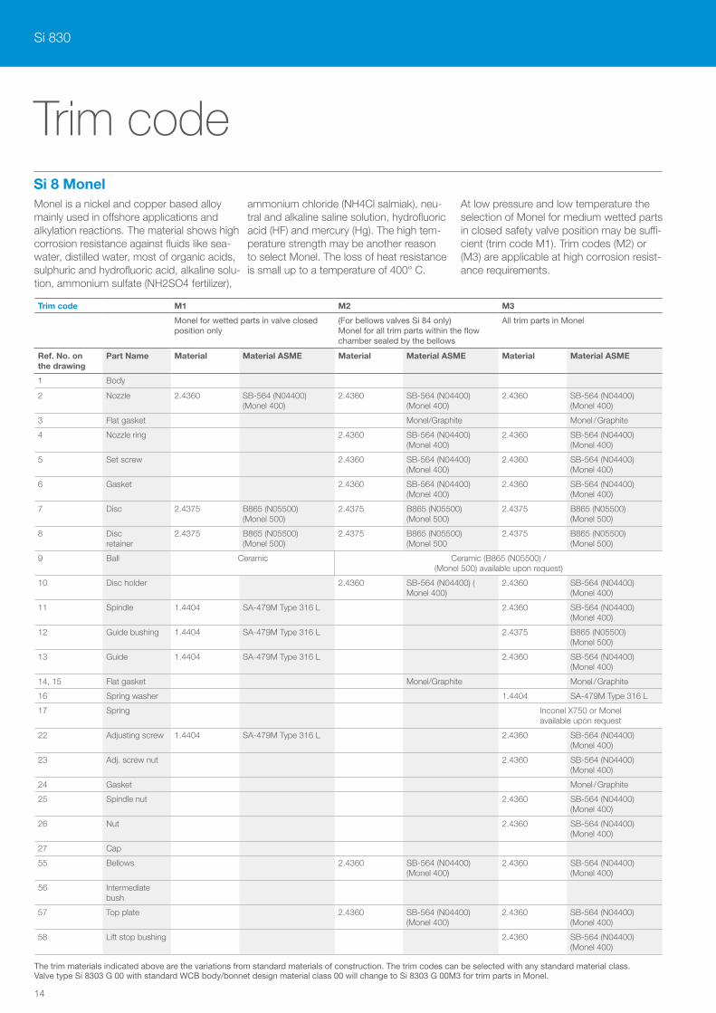
Si 8 Monel
Trim code
Monel is a nickel and copper based alloy mainly used in offshore applications and alkylation reactions. The material shows high corrosion resistance against fluids like sea-water, distilled water, most of organic acids, sulphuric and hydrofluoric acid, alkaline solu-tion, ammonium sulfate (NH2SO4 fertilizer),
ammonium chloride (NH4Cl salmiak), neu-tral and alkaline saline solution, hydrofluoric acid (HF) and mercury (Hg). The high tem-perature strength may be another reason to select Monel. The loss of heat resistance is small up to a temperature of 400° C.
At low pressure and low temperature the selection of Monel for medium wetted parts in closed safety valve position may be suffi-cient (trim code M1). Trim codes (M2) or (M3) are applicable at high corrosion resist-ance requirements.
Trim code M1 M2 M3
Monel for wetted parts in valve closed position only
(For bellows valves Si 84 only) Monel for all trim parts within the flow chamber sealed by the bellows
All trim parts in Monel
Ref. No. on the drawing
Part Name Material Material ASME Material Material ASME Material Material ASME
1 Body
2 Nozzle 2.4360 SB-564 (N04400) (Monel 400)
2.4360 SB-564 (N04400) (Monel 400)
2.4360 SB-564 (N04400) (Monel 400)
3 Flat gasket Monel/Graphite Monel / Graphite
4 Nozzle ring 2.4360 SB-564 (N04400) (Monel 400)
2.4360 SB-564 (N04400) (Monel 400)
5 Set screw 2.4360 SB-564 (N04400) (Monel 400)
2.4360 SB-564 (N04400) (Monel 400)
6 Gasket 2.4360 SB-564 (N04400) (Monel 400)
2.4360 SB-564 (N04400) (Monel 400)
7 Disc 2.4375 B865 (N05500) (Monel 500)
2.4375 B865 (N05500) (Monel 500)
2.4375 B865 (N05500) (Monel 500)
8 Disc retainer
2.4375 B865 (N05500) (Monel 500)
2.4375 B865 (N05500) (Monel 500
2.4375 B865 (N05500) (Monel 500)
9 Ball Ceramic Ceramic (B865 (N05500) / (Monel 500) available upon request)
10 Disc holder 2.4360 SB-564 (N04400) ( Monel 400)
2.4360 SB-564 (N04400) (Monel 400)
11 Spindle 1.4404 SA-479M Type 316 L 2.4360 SB-564 (N04400) (Monel 400)
12 Guide bushing 1.4404 SA-479M Type 316 L 2.4375 B865 (N05500) (Monel 500)
13 Guide 1.4404 SA-479M Type 316 L 2.4360 SB-564 (N04400) (Monel 400)
14, 15 Flat gasket Monel/Graphite Monel / Graphite
16 Spring washer 1.4404 SA-479M Type 316 L
17 Spring Inconel X750 or Monel available upon request
22 Adjusting screw 1.4404 SA-479M Type 316 L 2.4360 SB-564 (N04400) (Monel 400)
23 Adj. screw nut 2.4360 SB-564 (N04400) (Monel 400)
24 Gasket Monel / Graphite
25 Spindle nut 2.4360 SB-564 (N04400) (Monel 400)
26 Nut 2.4360 SB-564 (N04400) (Monel 400)
27 Cap
55 Bellows 2.4360 SB-564 (N04400) (Monel 400)
2.4360 SB-564 (N04400) (Monel 400)
56 Intermediate bush
57 Top plate 2.4360 SB-564 (N04400) (Monel 400)
2.4360 SB-564 (N04400) (Monel 400)
58 Lift stop bushing 2.4360 SB-564 (N04400) (Monel 400)
The trim materials indicated above are the variations from standard materials of construction. The trim codes can be selected with any standard material class. Valve type Si 8303 G 00 with standard WCB body/bonnet design material class 00 will change to Si 8303 G 00M3 for trim parts in Monel.
15
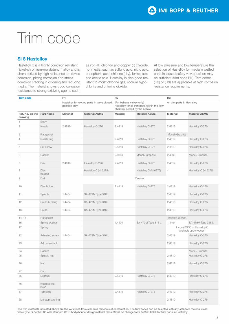
Si 8 HastelloyHastelloy C is a highly corrosion resistant nickel-chromium-molybdenum alloy and is characterized by high resistance to crevice corrosion, pitting corrosion and stress corrosion cracking in oxidizing and reducing media. The material shows good corrosion resistance to strong oxidizing agents such
as iron (III) chloride and copper (II) chloride, hot media, such as sulfuric acid, nitric acid, phosphoric acid, chlorine (dry), formic acid and acetic acid. Hastelloy is also good res-istant to moist chlorine gas, sodium hypo-chlorite and chlorine dioxide.
At low pressure and low temperature the selection of Hastelloy for medium wetted parts in closed safety valve position may be sufficient (trim code H1). Trim codes (H2) or (H3) are applicable at high corrosion resistance requirements.
Trim code
Trim code H1 H2 H3
Hastelloy for wetted parts in valve closed position only
(For bellows valves only) Hastelloy for all trim parts within the flow chamber sealed by the bellow
All trim parts in Hastelloy
Ref. No. on the drawing
Part Name Material Material ASME Material Material ASME Material Material ASME
1 Body
2 Nozzle 2.4819 Hastelloy C-276 2.4819 Hastelloy C-276 2.4819 Hastelloy C-276
3 Flat gasket Monel / Graphite
4 Nozzle ring 2.4819 Hastelloy C-276 2.4819 Hastelloy C-276
5 Set screw 2.4819 Hastelloy C-276 2.4819 Hastelloy C-276
6 Gasket 2.4360 Monel / Graphite 2.4360 Monel / Graphite
7 Disc 2.4819 Hastelloy C-276 2.4819 Hastelloy C-276 2.4819 Hastelloy C-276
8 Disc retainer
Hastelloy C (Ni 6275) Hastelloy C (Ni 6275) - Hastelloy C (Ni 6275)
9 Ball Ceramic
10 Disc holder 2.4819 Hastelloy C-276 2.4819 Hastelloy C-276
11 Spindle 1.4404 SA-479M Type 316 L 2.4819 Hastelloy C-276
12 Guide bushing 1.4404 SA-479M Type 316 L 2.4819 Hastelloy C-276
13 Guide 1.4404 SA-479M Type 316 L 2.4819 Hastelloy C-276
14, 15 Flat gasket Monel / Graphite
16 Spring washer 1.4404 SA-479M Type 316 L 1.4404 SA-479M Type 316 L
17 Spring Inconel X750 or Hastelloy C available upon request
22 Adjusting screw 1.4404 SA-479M Type 316 L 2.4819 Hastelloy C-276
23 Adj. screw nut 2.4819 Hastelloy C-276
24 Gasket Monel / Graphite
25 Spindle nut 2.4819 Hastelloy C-276
26 Nut 2.4819 Hastelloy C-276
27 Cap
55 Bellows 2.4819 Hastelloy C-276 2.4819 Hastelloy C-276
56 Intermediate bush
57 Top plate 2.4819 Hastelloy C-276 2.4819 Hastelloy C-276
58 Lift stop bushing 2.4819 Hastelloy C-276
The trim materials indicated above are the variations from standard materials of construction. The trim codes can be selected with any standard material class. Valve type Si 8403 G 00 with standard WCB body/bonnet designmaterial class 00 will be change to Si 8403 G 00H2 for trim parts in Hastelloy.
Si 830
16
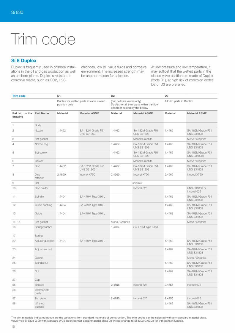
Si 8 Duplex
Trim code
Duplex is frequently used in o£shore install-ations in the oil and gas production as well as onshore plants. Duplex is resistant to corrosive media, such as CO2, H2S,
chlorides, low pH value fluids and corrosive environment. The increased strength may be another reason for selection.
At low pressure and low temperature, it may su¬cet that the wetted parts in the closed valve position are made of Duplex (code D1), at high risk of corrosion codes D2 or D3 are preferred.
Trim code D1 D2 D3
Duplex for wetted parts in valve closed position only
(For bellows valves only) Duplex for all trim parts within the flow chamber sealed by the bellow
All trim parts in Duplex
Ref. No. on the drawing
Part Name Material Material ASME Material Material ASME Material Material ASME
1 Body
2 Nozzle 1.4462 SA-182M Grade F51 UNS S31803
1.4462 SA-182M Grade F51 UNS S31803
1.4462 SA-182M Grade F51 UNS S31803
3 Flat gasket Monel / Graphite Monel / Graphite
4 Nozzle ring 1.4462 SA-182M Grade F51 UNS S31803
1.4462 SA-182M Grade F51 UNS S31803
5 Set screw 1.4462 SA-182M Grade F51 UNS S31803
1.4462 SA-182M Grade F51 UNS S31803)
6 Gasket Monel / Graphite Monel / Graphite
7 Disc 1.4462 SA-182M Grade F51 UNS S31803
1.4462 SA-182M Grade F51 UNS S31803
1.4462 SA-182M Grade F51 UNS S31803
8 Disc retainer
2.4669 Inconel X750 2.4669 Inconel X750 2.4669 Inconel X750
9 Ball Ceramic
10 Disc holder Inconel 625 UNS S31803 or Inconel 625
11 Spindle 1.4404 SA-479M Type 316 L 1.4462 SA-182M Grade F51 UNS S31803
12 Guide bushing 1.4404 SA-479M Type 316 L 1.4462 SA-182M Grade F51 UNS S31803
13 Guide 1.4404 SA-479M Type 316 L 1.4462 SA-182M Grade F51 UNS S31803
14, 15 Flat gasket Monel / Graphite Monel / Graphite
16 Spring washer 1.4404 SA-479M Type 316 L
17 Spring
22 Adjusting screw 1.4404 SA-479M Type 316 L 1.4462 SA-182M Grade F51 UNS S31803
23 Adj. screw nut 1.4462 SA-182M Grade F51 UNS S31803
24 Gasket Monel / Graphite
25 Spindle nut 1.4462 SA-182M Grade F51 UNS S31803
26 Nut 1.4462 SA-182M Grade F51 UNS S31803
27 Cap
55 Bellows 2.4856 Inconel 625 2.4856 Inconel 625
56 Intermediate bush
57 Top plate 2.4856 Inconel 625 2.4856 Inconel 625
58 Lift stop bushing
1.4462 SA-182M Grade F51 UNS S31803
The trim materials indicated above are the variations from standard materials of construction. The trim codes can be selected with any standard material class. Valve type Si 8303 G 00 with standard WCB body/bonnet designmaterial class 00 will be change to Si 8303 G 00D3 for trim parts in Duplex.
17
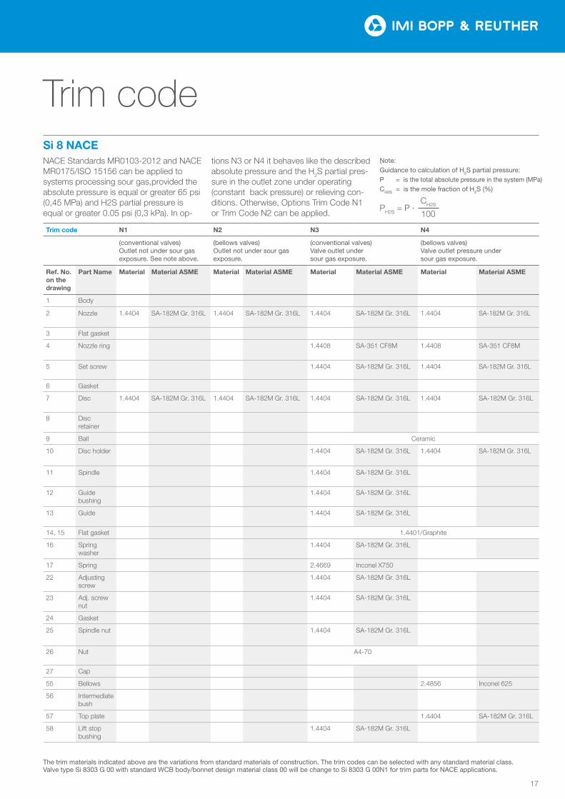
NACE Standards MR0103-2012 and NACE MR0175/ISO 15156 can be applied to systems processing sour gas,provided the absolute pressure is equal or greater 65 psi (0,45 MPa) and H2S partial pressure is equal or greater 0.05 psi (0,3 kPa). In op-
tions N3 or N4 it behaves like the described absolute pressure and the H2S partial pres-sure in the outlet zone under operating (constant back pressure) or relieving con-ditions. Otherwise, Options Trim Code N1 or Trim Code N2 can be applied.
.
Si 8 NACE
Trim code
Trim code N1 N2 N3 N4
(conventional valves) Outlet not under sour gas exposure. See note above.
(bellows valves) Outlet not under sour gas exposure.
(conventional valves) Valve outlet under sour gas exposure.
(bellows valves) Valve outlet pressure under sour gas exposure.
Ref. No. on the drawing
Part Name Material Material ASME Material Material ASME Material Material ASME Material Material ASME
1 Body
2 Nozzle 1.4404 SA-182M Gr. 316L 1.4404 SA-182M Gr. 316L 1.4404 SA-182M Gr. 316L 1.4404 SA-182M Gr. 316L
3 Flat gasket
4 Nozzle ring 1.4408 SA-351 CF8M 1.4408 SA-351 CF8M
5 Set screw 1.4404 SA-182M Gr. 316L 1.4404 SA-182M Gr. 316L
6 Gasket
7 Disc 1.4404 SA-182M Gr. 316L 1.4404 SA-182M Gr. 316L 1.4404 SA-182M Gr. 316L 1.4404 SA-182M Gr. 316L
8 Disc retainer
9 Ball Ceramic
10 Disc holder 1.4404 SA-182M Gr. 316L 1.4404 SA-182M Gr. 316L
11 Spindle 1.4404 SA-182M Gr. 316L
12 Guide bushing
1.4404 SA-182M Gr. 316L
13 Guide 1.4404 SA-182M Gr. 316L
14, 15 Flat gasket 1.4401/Graphite
16 Spring washer
1.4404 SA-182M Gr. 316L
17 Spring 2.4669 Inconel X750
22 Adjusting screw
1.4404 SA-182M Gr. 316L
23 Adj. screw nut
1.4404 SA-182M Gr. 316L
24 Gasket
25 Spindle nut 1.4404 SA-182M Gr. 316L
26 Nut A4-70
27 Cap
55 Bellows 2.4856 Inconel 625
56 Intermediate bush
57 Top plate 1.4404 SA-182M Gr. 316L
58 Lift stop bushing
1.4404 SA-182M Gr. 316L
CH2S
100PH2S = P ·
Note:Guidance to calculation of H2S partial pressure:P = is the total absolute pressure in the system (MPa)CH2S = is the mole fraction of H2S (%)
The trim materials indicated above are the variations from standard materials of construction. The trim codes can be selected with any standard material class. Valve type Si 8303 G 00 with standard WCB body/bonnet design material class 00 will be change to Si 8303 G 00N1 for trim parts for NACE applications.

Si 830
18
Orifice D
Inlet class 01 02 03 04 05 06 07
Material code
Class 150 x 150 300 x 150 300 x 150 600 x 150 900 x 300 1500 x 300 2500 x 300
NPS Inlet × outlet 1" x 2" 1" x 2" 1" x 2" 1" x 2" 1 1/2" x 2" 1 1/2" x 2" 1 1/2" x 3"
S1 [in] 4.50 4.50 4.50 4.50 5.50 5.50 7.00
S2 [in] 4.13 4.13 4.13 4.13 4.13 4.13 5.50
X [in] 1.73 1.73 1.73 1.73 2.24 2.24 2.83
H1 Si 81/83 [in] 17.32 17.32 17.32 17.32 20.67 20.67 26.57
H2 Si 84/85 [in] 19.09 19.09 19.09 19.09 22.64 22.64 28.74
Weight Si 81/83 [lbs] 34 36 36 36 62 62 106
Weight Si 84/85 [lbs] 36 38 38 38 69 69 113
Inlet temperature Max. set pressure [psig]
-51 °F to -21 °F 266 266 696 1392 2089 3481 5801 22 LCB
-20 °F to 100 °F 285 285 740 1480 2220 3705 600000 WCB
101 °F to 450 °F 185 285 615 1235 1845 3080 5135
451 °F to 800 °F 80 285 410 825 1235 2060 3430
451 °F to 800 °F 510 1015 1525 2540 4230 01 WC6801 °F to 1000 °F 215 430 650 1080 1800
-450 °F to -76 °F 275 275 720 1440 2160 3600 4000
04 CF8M
-75 °F to -21 °F 275 275 720 1440 2160 3600 6000
-20 °F to -100 °F 275 275 720 1440 2160 3600 6000
101 °F to 450 °F 180 275 495 975 1485 2480 4130
451 °F to 800 °F 80 275 420 845 1265 2110 3520
801 °F to 1000 °F 20 275 350 700 1050 1750 2915
Outlet temperature Max. outlet pressure [psig]
Si 81/83@100 °F 265 265 265 265 600 600 695 22
Si 81/83@100 °F 285 285 285 285 600 600 740 00/01
Si 81/83@100 °F 275 275 275 275 600 600 720 04
Si 84/85@100 °F 230 230 230 230 500 500 500 all
Inlet class 01 02 03 04 05 06 07
Material code
Class 150 x 150 300 x 150 300 x 150 600 x 150 900 x 300 1500 x 300 2500 x 300
NPS Inlet × outlet 1" x 2" 1" x 2" 1" x 2" 1" x 2" 1 1/2" x 2" 1 1/2" x 2" 1 1/2" x 3"
S1 [mm] 114.3 114.3 114.3 114.3 139.7 139.7 177.8
S2 [mm] 104.8 104.8 104.8 104.8 104.8 104.8 139.7
X [mm] 44 44 44 44 57 57 72
H1 Si 81/83 [mm] 440 440 440 440 525 525 675
H2 Si 84/85 [mm] 485 485 485 485 575 575 730
Weight Si 81/83 [kg] 15 16 16 16 28 28 48
Weight Si 84/85 [kg] 16 17 17 17 31 31 51
Inlet temperature Max. set pressure [bar g]
-46 °C to -30 °C 18.3 18.3 48.0 96.0 144.0 240.0 400.0 22 LCB
-29 °C to 38 °C 19.7 19.7 51.0 102.0 153.1 255.5 413.700 WCB
39 °C to 232 °C 12.8 19.7 42.4 85.2 127.2 212.4 354.0
233 °C to 427 °C 5.5 19.7 28.3 56.9 85.2 142.0 236.5
233 °C to 427 °C 35.2 70.0 105.1 175.1 291.6 01 WC6428 °C to 538 °C 14.8 29.6 44.8 74.5 124.1
-268 °C to -60 °C 19.0 19.0 49.6 99.3 148.9 248.2 275.8
04 CF8M
-59 °C to -30 °C 19.0 19.0 49.6 99.3 148.9 248.2 413.7
-29 °C to 38 °C 19.0 19.0 49.6 99.3 148.9 248.2 413.7
39 °C to 232 °C 12.4 19.0 34.1 67.2 102.4 171.0 284.8
233 °C to 427 °C 5.5 19.0 29.0 58.3 87.2 145.5 242.7
428 °C to 538 °C 1.4 19.0 24.1 48.3 72.4 120.7 201.0
Outlet temperature Max. outlet pressure [bar g]
Si 81/83@38 °C 18.3 18.3 18.3 18.3 41.4 41.4 47.9 22
Si 81/83@38 °C 19.7 19.7 19.7 19.7 41.4 41.4 51.0 00/01
Si 81/83@38 °C 19.0 19.0 19.0 19.0 41.4 41.4 49.6 04
Si 84/85@38 °C 15.9 15.9 15.9 15.9 34.5 34.5 34.5 all
Effective area 0.110 in² / 71 mm²
Minimum set pressures
Si 830x.57 4 psig 0.24 bar g
Si 830x 8 psig 0.5 bar g
Si 840x 22 psig 1.5 bar g

19
0102
0304
0506
07
Tem
pera
tur [
°F]
Druck [psi]
0
200
400
600
800
1000
0 1000 2000 3000 4000 5000 6000
0
100
200
300
400
500
0 100 200 300 400
Tem
pera
tur [
°C]
Druck [bar]
Tem
pera
tur [
°F]
Druck [psi]
−400
−200
0
200
400
600
800
1000
0 1000 2000 3000 4000 5000 6000
−200
−100
0
100
200
300
400
500
0 100 200 300 400Te
mpe
ratu
r [°C
]Druck [bar]
0102
0304
0506
07
Tem
pera
tur [
°F]
Druck [psi]
0
200
400
600
800
1000
0 1000 2000 3000 4000 5000 6000
0
100
200
300
400
500
0 100 200 300 400
Tem
pera
tur [
°C]
Druck [bar]
Tem
pera
tur [
°F]
Druck [psi]
−400
−200
0
200
400
600
800
1000
0 1000 2000 3000 4000 5000 6000
−200
−100
0
100
200
300
400
500
0 100 200 300 400Te
mpe
ratu
r [°C
]
Druck [bar]
Orifice D
01 WC6
00 WCB
04 CF8M
Inle
t te
mp
erat
ure
[ °C
] In
let
tem
per
atur
e [ °
C]
Inle
t te
mp
erat
ure
[°F]
In
let
tem
per
atur
e [°
F]
Si 81/83
S1conventional
S2
x
H1
1000
800
600
400
200
0
1000
800
600
400
200
0
-200
-400
500
400
300
200
100
0
500
400
300
200
100
0
-100
-200
Set Pressure [bar g] 0 100 200 300 400
0 1000 2000 3000 4000 5000 6000Set Pressure [psig]
0 1000 2000 3000 4000 5000 6000 Set Pressure [psig]
Set Pressure [bar g] 0 100 200 300 400
01 02 03 04 05 06 07
with bellows
Si 84/85
S1
S2
H2
x
Selection chart
Si 830
20
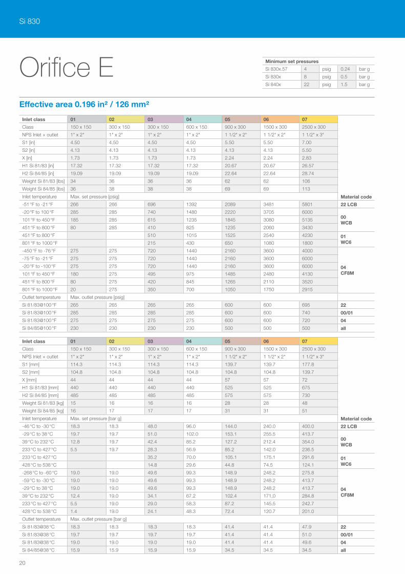
Orifice E
Inlet class 01 02 03 04 05 06 07
Material code
Class 150 x 150 300 x 150 300 x 150 600 x 150 900 x 300 1500 x 300 2500 x 300
NPS Inlet × outlet 1" x 2" 1" x 2" 1" x 2" 1" x 2" 1 1/2" x 2" 1 1/2" x 2" 1 1/2" x 3"
S1 [in] 4.50 4.50 4.50 4.50 5.50 5.50 7.00
S2 [in] 4.13 4.13 4.13 4.13 4.13 4.13 5.50
X [in] 1.73 1.73 1.73 1.73 2.24 2.24 2.83
H1 Si 81/83 [in] 17.32 17.32 17.32 17.32 20.67 20.67 26.57
H2 Si 84/85 [in] 19.09 19.09 19.09 19.09 22.64 22.64 28.74
Weight Si 81/83 [lbs] 34 36 36 36 62 62 106
Weight Si 84/85 [lbs] 36 38 38 38 69 69 113
Inlet temperature Max. set pressure [psig]
-51 °F to -21 °F 266 266 696 1392 2089 3481 5801 22 LCB
-20 °F to 100 °F 285 285 740 1480 2220 3705 600000 WCB
101 °F to 450 °F 185 285 615 1235 1845 3080 5135
451 °F to 800 °F 80 285 410 825 1235 2060 3430
451 °F to 800 °F 510 1015 1525 2540 4230 01 WC6801 °F to 1000 °F 215 430 650 1080 1800
-450 °F to -76 °F 275 275 720 1440 2160 3600 4000
04 CF8M
-75 °F to -21 °F 275 275 720 1440 2160 3600 6000
-20 °F to -100 °F 275 275 720 1440 2160 3600 6000
101°F to 450 °F 180 275 495 975 1485 2480 4130
451 °F to 800 °F 80 275 420 845 1265 2110 3520
801 °F to 1000 °F 20 275 350 700 1050 1750 2915
Outlet temperature Max. outlet pressure [psig]
Si 81/83@100 °F 265 265 265 265 600 600 695 22
Si 81/83@100 °F 285 285 285 285 600 600 740 00/01
Si 81/83@100 °F 275 275 275 275 600 600 720 04
Si 84/85@100 °F 230 230 230 230 500 500 500 all
Inlet class 01 02 03 04 05 06 07
Material code
Class 150 x 150 300 x 150 300 x 150 600 x 150 900 x 300 1500 x 300 2500 x 300
NPS Inlet × outlet 1" x 2" 1" x 2" 1" x 2" 1" x 2" 1 1/2" x 2" 1 1/2" x 2" 1 1/2" x 3"
S1 [mm] 114.3 114.3 114.3 114.3 139.7 139.7 177.8
S2 [mm] 104.8 104.8 104.8 104.8 104.8 104.8 139.7
X [mm] 44 44 44 44 57 57 72
H1 Si 81/83 [mm] 440 440 440 440 525 525 675
H2 Si 84/85 [mm] 485 485 485 485 575 575 730
Weight Si 81/83 [kg] 15 16 16 16 28 28 48
Weight Si 84/85 [kg] 16 17 17 17 31 31 51
Inlet temperature Max. set pressure [bar g]
-46 °C to -30 °C 18.3 18.3 48.0 96.0 144.0 240.0 400.0 22 LCB
-29 °C to 38 °C 19.7 19.7 51.0 102.0 153.1 255.5 413.700 WCB
39 °C to 232 °C 12.8 19.7 42.4 85.2 127.2 212.4 354.0
233 °C to 427 °C 5.5 19.7 28.3 56.9 85.2 142.0 236.5
233 °C to 427 °C 35.2 70.0 105.1 175.1 291.6 01 WC6428 °C to 538 °C 14.8 29.6 44.8 74.5 124.1
-268 °C to -60 °C 19.0 19.0 49.6 99.3 148.9 248.2 275.8
04 CF8M
-59 °C to -30 °C 19.0 19.0 49.6 99.3 148.9 248.2 413.7
-29 °C to 38 °C 19.0 19.0 49.6 99.3 148.9 248.2 413.7
39 °C to 232 °C 12.4 19.0 34.1 67.2 102.4 171.0 284.8
233 °C to 427 °C 5.5 19.0 29.0 58.3 87.2 145.5 242.7
428 °C to 538 °C 1.4 19.0 24.1 48.3 72.4 120.7 201.0
Outlet temperature Max. outlet pressure [bar g]
Si 81/83@38 °C 18.3 18.3 18.3 18.3 41.4 41.4 47.9 22
Si 81/83@38 °C 19.7 19.7 19.7 19.7 41.4 41.4 51.0 00/01
Si 81/83@38 °C 19.0 19.0 19.0 19.0 41.4 41.4 49.6 04
Si 84/85@38 °C 15.9 15.9 15.9 15.9 34.5 34.5 34.5 all
Effective area 0.196 in² / 126 mm²
Minimum set pressures
Si 830x.57 4 psig 0.24 bar g
Si 830x 8 psig 0.5 bar g
Si 840x 22 psig 1.5 bar g
21
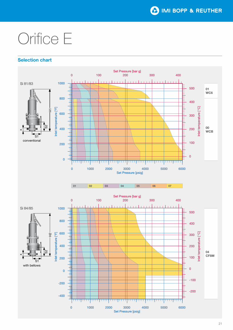
Orifice E
0102
0304
0506
07
Tem
pera
tur [
°F]
Druck [psi]
0
200
400
600
800
1000
0 1000 2000 3000 4000 5000 6000
0
100
200
300
400
500
0 100 200 300 400
Tem
pera
tur [
°C]
Druck [bar]
Tem
pera
tur [
°F]
Druck [psi]
−400
−200
0
200
400
600
800
1000
0 1000 2000 3000 4000 5000 6000
−200
−100
0
100
200
300
400
500
0 100 200 300 400Te
mpe
ratu
r [°C
]Druck [bar]
0102
0304
0506
07
Tem
pera
tur [
°F]
Druck [psi]
0
200
400
600
800
1000
0 1000 2000 3000 4000 5000 6000
0
100
200
300
400
500
0 100 200 300 400
Tem
pera
tur [
°C]
Druck [bar]
Tem
pera
tur [
°F]
Druck [psi]
−400
−200
0
200
400
600
800
1000
0 1000 2000 3000 4000 5000 6000
−200
−100
0
100
200
300
400
500
0 100 200 300 400Te
mpe
ratu
r [°C
]
Druck [bar]
01 WC6
00 WCB
04 CF8M
Inle
t te
mp
erat
ure
[ °C
] In
let
tem
per
atur
e [ °
C]
Inle
t te
mp
erat
ure
[°F]
In
let
tem
per
atur
e [°
F]
Si 81/83
S1conventional
S2
x
H1
1000
800
600
400
200
0
1000
800
600
400
200
0
-200
-400
500
400
300
200
100
0
500
400
300
200
100
0
-100
-200
Set Pressure [bar g] 0 100 200 300 400
0 1000 2000 3000 4000 5000 6000Set Pressure [psig]
0 1000 2000 3000 4000 5000 6000 Set Pressure [psig]
Set Pressure [bar g] 0 100 200 300 400
01 02 03 04 05 06 07
with bellows
Si 84/85
S1
S2
H2
x
Selection chart
Si 830
22
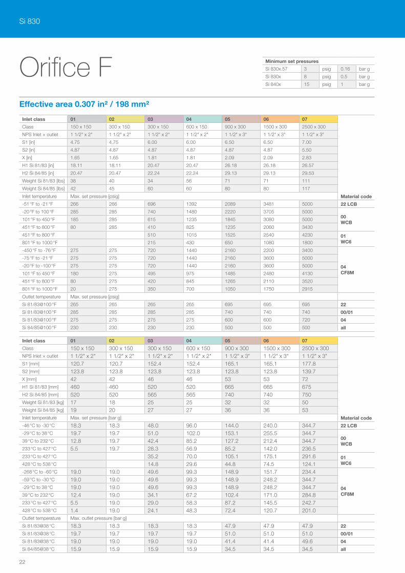
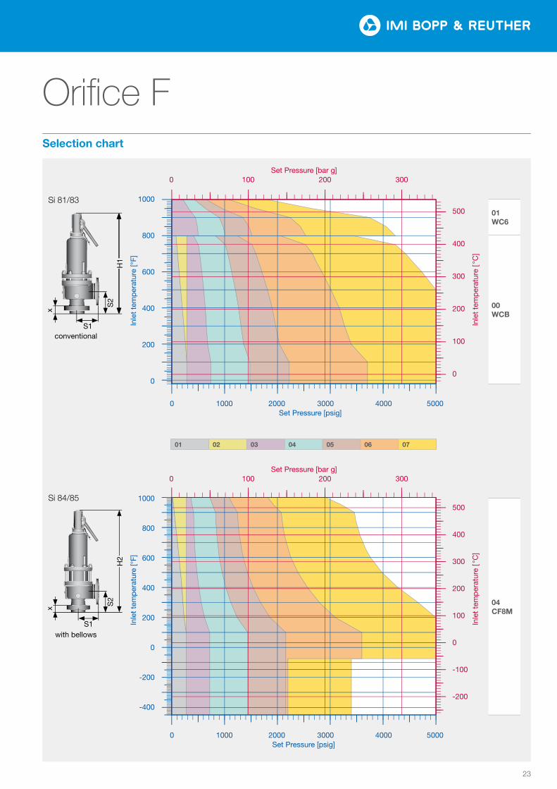
Orifice F
Inlet class 01 02 03 04 05 06 07
Material code
Class 150 x 150 300 x 150 300 x 150 600 x 150 900 x 300 1500 x 300 2500 x 300
NPS Inlet × outlet 1 1/2" x 2" 1 1/2" x 2" 1 1/2" x 2" 1 1/2" x 2" 1 1/2" x 3" 1 1/2" x 3" 1 1/2" x 3"
S1 [in] 4.75 4.75 6.00 6.00 6.50 6.50 7.00
S2 [in] 4.87 4.87 4.87 4.87 4.87 4.87 5.50
X [in] 1.65 1.65 1.81 1.81 2.09 2.09 2.83
H1 Si 81/83 [in] 18.11 18.11 20.47 20.47 26.18 26.18 26.57
H2 Si 84/85 [in] 20.47 20.47 22.24 22.24 29.13 29.13 29.53
Weight Si 81/83 [lbs] 38 40 34 56 71 71 111
Weight Si 84/85 [lbs] 42 45 60 60 80 80 117
Inlet temperature Max. set pressure [psig]
-51 °F to -21 °F 266 266 696 1392 2089 3481 5000 22 LCB
-20 °F to 100 °F 285 285 740 1480 2220 3705 500000 WCB
101 °F to 450 °F 185 285 615 1235 1845 3080 5000
451 °F to 800 °F 80 285 410 825 1235 2060 3430
451 °F to 800 °F 510 1015 1525 2540 4230 01 WC6801 °F to 1000 °F 215 430 650 1080 1800
-450 °F to -76 °F 275 275 720 1440 2160 2200 3400
04 CF8M
-75 °F to -21 °F 275 275 720 1440 2160 3600 5000
-20 °F to -100 °F 275 275 720 1440 2160 3600 5000
101 °F to 450 °F 180 275 495 975 1485 2480 4130
451 °F to 800 °F 80 275 420 845 1265 2110 3520
801 °F to 1000 °F 20 275 350 700 1050 1750 2915
Outlet temperature Max. set pressure [psig]
Si 81/83@100 °F 265 265 265 265 695 695 695 22
Si 81/83@100 °F 285 285 285 285 740 740 740 00/01
Si 81/83@100 °F 275 275 275 275 600 600 720 04
Si 84/85@100 °F 230 230 230 230 500 500 500 all
Effective area 0.307 in² / 198 mm²
Inlet class 01 02 03 04 05 06 07
Material code
Class 150 x 150 300 x 150 300 x 150 600 x 150 900 x 300 1500 x 300 2500 x 300NPS Inlet × outlet 1 1/2" x 2" 1 1/2" x 2" 1 1/2" x 2" 1 1/2" x 2" 1 1/2" x 3" 1 1/2" x 3" 1 1/2" x 3"S1 [mm] 120.7 120.7 152.4 152.4 165.1 165.1 177.8S2 [mm] 123.8 123.8 123.8 123.8 123.8 123.8 139.7X [mm] 42 42 46 46 53 53 72H1 Si 81/83 [mm] 460 460 520 520 665 665 675H2 Si 84/85 [mm] 520 520 565 565 740 740 750Weight Si 81/83 [kg] 17 18 25 25 32 32 50Weight Si 84/85 [kg] 19 20 27 27 36 36 53Inlet temperature Max. set pressure [bar g]
-46 °C to -30 °C 18.3 18.3 48.0 96.0 144.0 240.0 344.7 22 LCB
-29 °C to 38 °C 19.7 19.7 51.0 102.0 153.1 255.5 344.700 WCB
39 °C to 232 °C 12.8 19.7 42.4 85.2 127.2 212.4 344.7233 °C to 427 °C 5.5 19.7 28.3 56.9 85.2 142.0 236.5233 °C to 427 °C 35.2 70.0 105.1 175.1 291.6 01
WC6428 °C to 538 °C 14.8 29.6 44.8 74.5 124.1-268 °C to -60 °C 19.0 19.0 49.6 99.3 148.9 151.7 234.4
04 CF8M
-59 °C to -30 °C 19.0 19.0 49.6 99.3 148.9 248.2 344.7-29 °C to 38 °C 19.0 19.0 49.6 99.3 148.9 248.2 344.739 °C to 232 °C 12.4 19.0 34.1 67.2 102.4 171.0 284.8233 °C to 427 °C 5.5 19.0 29.0 58.3 87.2 145.5 242.7428 °C to 538 °C 1.4 19.0 24.1 48.3 72.4 120.7 201.0Outlet temperature Max. outlet pressure [bar g]
Si 81/83@38 °C 18.3 18.3 18.3 18.3 47.9 47.9 47.9 22
Si 81/83@38 °C 19.7 19.7 19.7 19.7 51.0 51.0 51.0 00/01
Si 81/83@38 °C 19.0 19.0 19.0 19.0 41.4 41.4 49.6 04
Si 84/85@38 °C 15.9 15.9 15.9 15.9 34.5 34.5 34.5 all
Minimum set pressures
Si 830x.57 3 psig 0.16 bar g
Si 830x 8 psig 0.5 bar g
Si 840x 15 psig 1 bar g
23
Orifice F
0102
0304
0506
07
Tem
pera
tur [
°F]
Druck [psi]
0
200
400
600
800
1000
0 1000 2000 3000 4000 5000
0
100
200
300
400
500
0 100 200 300
Tem
pera
tur [
°C]
Druck [bar]
Tem
pera
tur [
°F]
Druck [psi]
−400
−200
0
200
400
600
800
1000
0 1000 2000 3000 4000 5000
−200
−100
0
100
200
300
400
500
0 100 200 300Te
mpe
ratu
r [°C
]Druck [bar]
0102
0304
0506
07
Tem
pera
tur [
°F]
Druck [psi]
0
200
400
600
800
1000
0 1000 2000 3000 4000 5000
0
100
200
300
400
500
0 100 200 300
Tem
pera
tur [
°C]
Druck [bar]
Tem
pera
tur [
°F]
Druck [psi]
−400
−200
0
200
400
600
800
1000
0 1000 2000 3000 4000 5000
−200
−100
0
100
200
300
400
500
0 100 200 300Te
mpe
ratu
r [°C
]
Druck [bar]
01 WC6
00 WCB
04 CF8M
Inle
t te
mp
erat
ure
[ °C
] In
let
tem
per
atur
e [ °
C]
Inle
t te
mp
erat
ure
[°F]
In
let
tem
per
atur
e [°
F]
Si 81/83
S1conventional
S2
x
H1
1000
800
600
400
200
0
1000
800
600
400
200
0
-200
-400
500
400
300
200
100
0
500
400
300
200
100
0
-100
-200
Set Pressure [bar g] 0 100 200 300
0 1000 2000 3000 4000 5000Set Pressure [psig]
0 1000 2000 3000 4000 5000 Set Pressure [psig]
Set Pressure [bar g] 0 100 200 300
01 02 03 04 05 06 07
with bellows
Si 84/85
S1
S2
H2
x
Selection chart
Si 830
24
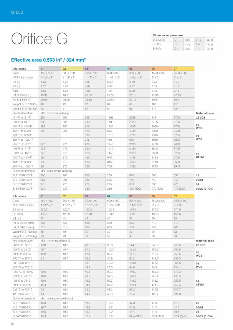
Orifice G
Inlet class 01 02 03 04 05 06 07
Material code
Class 150 x 150 300 x 150 300 x 150 600 x 150 900 x 300 1500 x 300 2500 x 300
NPS Inlet × outlet 1 1/2" x 3" 1 1/2" x 3" 1 1/2" x 3" 1 1/2" x 3" 1 1/2" x 3" 2" x 3" 2" x 3"
S1 [in] 4.75 4.75 6.00 6.00 6.50 6.75 6.75
S2 [in] 4.87 4.87 4.87 4.87 4.87 6.13 6.13
X [in] 1.65 1.65 1.81 1.81 2.09 3.15 3.15
H1 Si 81/83 [in] 18.31 18.31 22.05 22.05 26.18 27.95 27.95
H2 Si 84/85 [in] 20.08 20.08 23.82 23.82 29.13 30.91 30.91
Weight Si 81/83 [lbs] 40 42 67 67 89 100 115
Weight Si 84/85 [lbs] 45 51 84 84 95 111 124
Inlet temperature Max. set pressure [psig]
-51 °F to -21 °F 266 266 696 1392 2089 3481 3705 22 LCB
-20 °F to 100 °F 285 285 740 1480 2220 3705 370500 WCB
101 °F to 450 °F 185 285 615 1235 1845 3080 3705
451 °F to 800 °F 80 285 410 825 1235 2060 3430
451 °F to 800 °F 510 1015 1525 2540 3705 01 WC6801 °F to 1000 °F 215 430 650 1080 1800
-450 °F to -76 °F 275 275 720 1440 2160 2450 2600
04 CF8M
-75 °F to -21 °F 275 275 720 1440 2160 3600 3705
-20 °F to -100 °F 275 275 720 1440 2160 3600 3705
101 °F to 450 °F 180 275 495 975 1485 2480 3705
451 °F to 800 °F 80 275 420 845 1265 2110 3520
801 °F to 1000 °F 20 275 350 700 1050 1750 2915
Outlet temperature Max. outlet pressure [psig]
Si 81/83@100 °F 265 265 265 265 695 695 695 22
Si 81/83@100 °F 285 285 285 285 740 740 740 00/01
Si 81/83@100 °F 275 275 275 275 600 600 720 04
Si 84/85@100 °F 230 230 230 230 470 (500) 470 (500) 470 (500) 00/22 (01/04)
Inlet class 01 02 03 04 05 06 07
Material code
Class 150 x 150 300 x 150 300 x 150 600 x 150 900 x 300 1500 x 300 2500 x 300
NPS Inlet × outlet 1 1/2" x 3" 1 1/2" x 3" 1 1/2" x 3" 1 1/2" x 3" 1 1/2" x 3" 2" x 3" 2" x 3"
S1 [mm] 120.7 120.7 152.4 152.4 165.1 171.5 171.5
S2 [mm] 123.8 123.8 123.8 123.8 123.8 155.6 155.6
X [mm] 42 42 46 46 53 80 80
H1 Si 81/83 [mm] 465 465 560 560 665 710 710
H2 Si 84/85 [mm] 510 510 605 605 740 785 785
Weight Si 81/83 [kg] 18 19 30 30 40 45 52
Weight Si 84/85 [kg] 20 23 38 38 43 50 56
Inlet temperature Max. set pressure [bar g]
-46 °C to -30 °C 18.3 18.3 48.0 96.0 144.0 240.0 255.5 22 LCB
-29 °C to 38 °C 19.7 19.7 51.0 102.0 153.1 255.5 255.500 WCB
39 °C to 232 °C 12.8 19.7 42.4 85.2 127.2 212.4 255.5
233 °C to 427 °C 5.5 19.7 28.3 56.9 85.2 142.0 236.5
233 °C to 427 °C 35.2 70.0 105.1 175.1 255.5 01 WC6428 °C to 538 °C 14.8 29.6 44.8 74.5 124.1
-268 °C to -60 °C 19.0 19.0 49.6 99.3 148.9 168.9 179.3
04 CF8M
-59 °C to -30 °C 19.0 19.0 49.6 99.3 148.9 248.2 255.5
-29 °C to 38 °C 19.0 19.0 49.6 99.3 148.9 248.2 255.5
39 °C to 232 °C 12.4 19.0 34.1 67.2 102.4 171.0 255.5
233 °C to 427 °C 5.5 19.0 29.0 58.3 87.2 145.5 242.7
428 °C to 538 °C 1.4 19.0 24.1 48.3 72.4 120.7 201.0
Outlet temperature Max. outlet pressure [bar g]
Si 81/83@38 °C 18.3 18.3 18.3 18.3 47.9 47.9 47.9 22
Si 81/83@38 °C 19.7 19.7 19.7 19.7 51.0 51.0 51.0 00/01
Si 81/83@38 °C 19.0 19.0 19.0 19.0 41.4 41.4 49.6 04
Si 84/85@38 °C 15.9 15.9 15.9 15.9 32.4 (34.5) 32.4 (34.5) 32.4 (34.5) 00/22 (01/04)
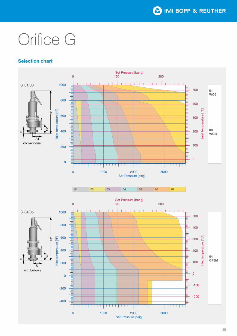
Effective area 0.503 in² / 324 mm²
Minimum set pressures
Si 830x.57 2 psig 0.13 bar g
Si 830x 8 psig 0.5 bar g
Si 840x 21 psig 1.4 bar g
25
Orifice G
0102
0304
0506
07
Tem
pera
tur [
°F]
Druck [psi]
0
200
400
600
800
1000
0 1000 2000 3000
0
100
200
300
400
500
0 100 200
Tem
pera
tur [
°C]
Druck [bar]
Tem
pera
tur [
°F]
Druck [psi]
−400
−200
0
200
400
600
800
1000
0 1000 2000 3000
−200
−100
0
100
200
300
400
500
0 100 200Te
mpe
ratu
r [°C
]Druck [bar]
0102
0304
0506
07
Tem
pera
tur [
°F]
Druck [psi]
0
200
400
600
800
1000
0 1000 2000 3000
0
100
200
300
400
500
0 100 200
Tem
pera
tur [
°C]
Druck [bar]
Tem
pera
tur [
°F]
Druck [psi]
−400
−200
0
200
400
600
800
1000
0 1000 2000 3000
−200
−100
0
100
200
300
400
500
0 100 200Te
mpe
ratu
r [°C
]
Druck [bar]
01 WC6
00 WCB
04 CF8M
Inle
t te
mp
erat
ure
[ °C
] In
let
tem
per
atur
e [ °
C]
Inle
t te
mp
erat
ure
[°F]
In
let
tem
per
atur
e [°
F]
Si 81/83
S1conventional
S2
x
H1
1000
800
600
400
200
0
1000
800
600
400
200
0
-200
-400
500
400
300
200
100
0
500
400
300
200
100
0
-100
-200
Set Pressure [bar g] 0 100 200
0 1000 2000 3000Set Pressure [psig]
0 1000 2000 3000 Set Pressure [psig]
Set Pressure [bar g] 0 100 200
01 02 03 04 05 06 07
with bellows
Si 84/85
S1
S2
H2
x
Selection chart

Si 830
26
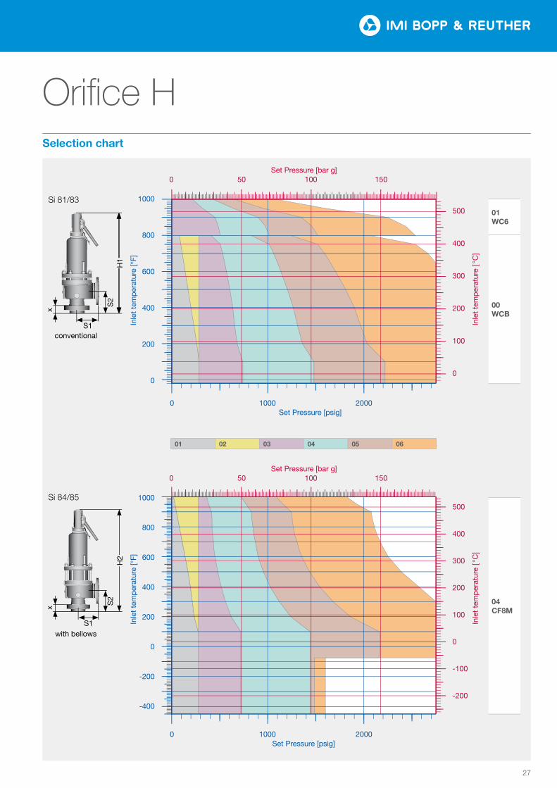
Orifice H
Inlet class 01 02 03 04 05 06
Material code
Class 150 x 150 300 x 150 300 x 150 600 x 150 900 x 150 1500 x 300
NPS Inlet × outlet 1 1/2" x 3" 1 1/2" x 3" 2" x 3" 2" x 3" 2" x 3" 2" x 3"
S1 [in] 4.87 4.87 4.87 6.37 6.37 6.37
S2 [in] 5.13 5.13 5.13 6.06 6.06 6.06
X [in] 1.73 1.73 1.89 2.09 2.64 2.64
H1 Si 81/83 [in] 21.26 21.26 22.64 27.95 27.95 27.95
H2 Si 84/85 [in] 23.03 23.03 24.80 30.71 30.71 30.71
Weight Si 81/83 [lbs] 60 62 80 115 139 150
Weight Si 84/85 [lbs] 64 67 86 133 150 164
Inlet temperature Max. set pressure [psig]
-51 °F to -21 °F 266 266 696 1392 2089 3481 22 LCB
-20 °F to 100 °F 285 285 740 1480 2220 370500 WCB
101 °F to 450 °F 185 285 615 1235 1845 3080
451 °F to 800 °F 80 285 410 825 1235 2060
451 °F to 800 °F 510 1015 1525 2540 01 WC6801 °F to 1000 °F 215 430 650 1080
-450 °F to -76 °F 275 275 720 1440 2160 2450
04 CF8M
-75 °F to -21 °F 275 275 720 1440 2160 3600
-20 °F to -100 °F 275 275 720 1440 2160 3600
101 °F to 450 °F 180 275 495 975 1485 2480
451 °F to 800 °F 80 275 420 845 1265 2110
801 °F to 1000 °F 20 275 350 700 1050 1750
Outlet temperature Max. outlet pressure [psig]
Si 81/83@100 °F 265 265 265 265 265 695 22
Si 81/83@100 °F 285 285 285 285 285 740 00/01
Si 81/83@100 °F 275 275 275 275 275 600 04
Si 84/85@100 °F 230 230 230 230 230 415 all
Effective area 0.785 in² / 506 mm²
Inlet class 01 02 03 04 05 06
Material code
Class 150 x 150 300 x 150 300 x 150 600 x 150 900 x 150 1500 x 300
NPS Inlet × outlet 1 1/2" x 3" 1 1/2" x 3" 2" x 3" 2" x 3" 2" x 3" 2" x 3"
S1 [mm] 123.8 123.8 123.8 161.9 161.9 161.9
S2 [mm] 130.2 130.2 130.2 154.0 154.0 154.0
X [mm] 44 44 48 53 67 67
H1 Si 81/83 [mm] 540 540 575 710 710 710
H2 Si 84/85 [mm] 585 585 630 780 780 780
Weight Si 81/83 [kg] 27 28 36 52 63 68
Weight Si 84/85 [kg] 29 30 39 60 68 74
Inlet temperature Max. set pressure [bar g]
-46 °C to -30 °C 18.3 18.3 48.0 96.0 144.0 189.6 22 LCB
-29 °C to 38 °C 19.7 19.7 51.0 102.0 153.1 189.600 WCB
39 °C to 232 °C 12.8 19.7 42.4 85.2 127.2 189.6
233 °C to 427 °C 5.5 19.7 28.3 56.9 85.2 142.0
233 °C to 427 °C 35.2 70.0 105.1 175.1 01 WC6428 °C to 538 °C 14.8 29.6 44.8 74.5
-268 °C to -60 °C 19.0 19.0 49.6 99.3 102.4 110.3
04 CF8M
-59 °C to -30 °C 19.0 19.0 49.6 99.3 148.9 189.6
-29 °C to 38 °C 19.0 19.0 49.6 99.3 148.9 189.6
39 °C to 232 °C 12.4 19.0 34.1 67.2 102.4 171.0
233 °C to 427 °C 5.5 19.0 29.0 58.3 87.2 145.5
428 °C to 538 °C 1.4 19.0 24.1 48.3 72.4 120.7
Outlet temperature Max. outlet pressure [bar g]
Si 81/83@38 °C 18.3 18.3 18.3 18.3 18.3 47.9 22
Si 81/83@38 °C 19.7 19.7 19.7 19.7 19.7 51.0 00/01
Si 81/83@38 °C 19.0 19.0 19.0 19.0 19.0 41.4 04
Si 84/85@38 °C 15.9 15.9 15.9 15.9 15.9 28.6 all
Minimum set pressures
Si 830x.57 4 psig 0.22 bar g
Si 830x 8 psig 0.5 bar g
Si 840x 15 psig 1 bar g
27
Orifice H
0102
0304
0506
Tem
pera
tur [
°F]
Druck [psi]
0
200
400
600
800
1000
0 1000 2000
0
100
200
300
400
500
0 50 100 150
Tem
pera
tur [
°C]
Druck [bar]
Tem
pera
tur [
°F]
Druck [psi]
−400
−200
0
200
400
600
800
1000
0 1000 2000
−200
−100
0
100
200
300
400
500
0 50 100 150Te
mpe
ratu
r [°C
]Druck [bar]
0102
0304
0506
Tem
pera
tur [
°F]
Druck [psi]
0
200
400
600
800
1000
0 1000 2000
0
100
200
300
400
500
0 50 100 150
Tem
pera
tur [
°C]
Druck [bar]
Tem
pera
tur [
°F]
Druck [psi]
−400
−200
0
200
400
600
800
1000
0 1000 2000
−200
−100
0
100
200
300
400
500
0 50 100 150Te
mpe
ratu
r [°C
]
Druck [bar]
01 WC6
00 WCB
04 CF8M
Inle
t te
mp
erat
ure
[ °C
] In
let
tem
per
atur
e [ °
C]
Inle
t te
mp
erat
ure
[°F]
In
let
tem
per
atur
e [°
F]
Si 81/83
S1conventional
S2
x
H1
1000
800
600
400
200
0
1000
800
600
400
200
0
-200
-400
500
400
300
200
100
0
500
400
300
200
100
0
-100
-200
Set Pressure [bar g] 0 50 100 150
0 1000 2000Set Pressure [psig]
0 1000 2000 Set Pressure [psig]
Set Pressure [bar g] 0 50 100 150
01 02 03 04 05 06
with bellows
Si 84/85
S1
S2
H2
x
Selection chart
Si 830
28
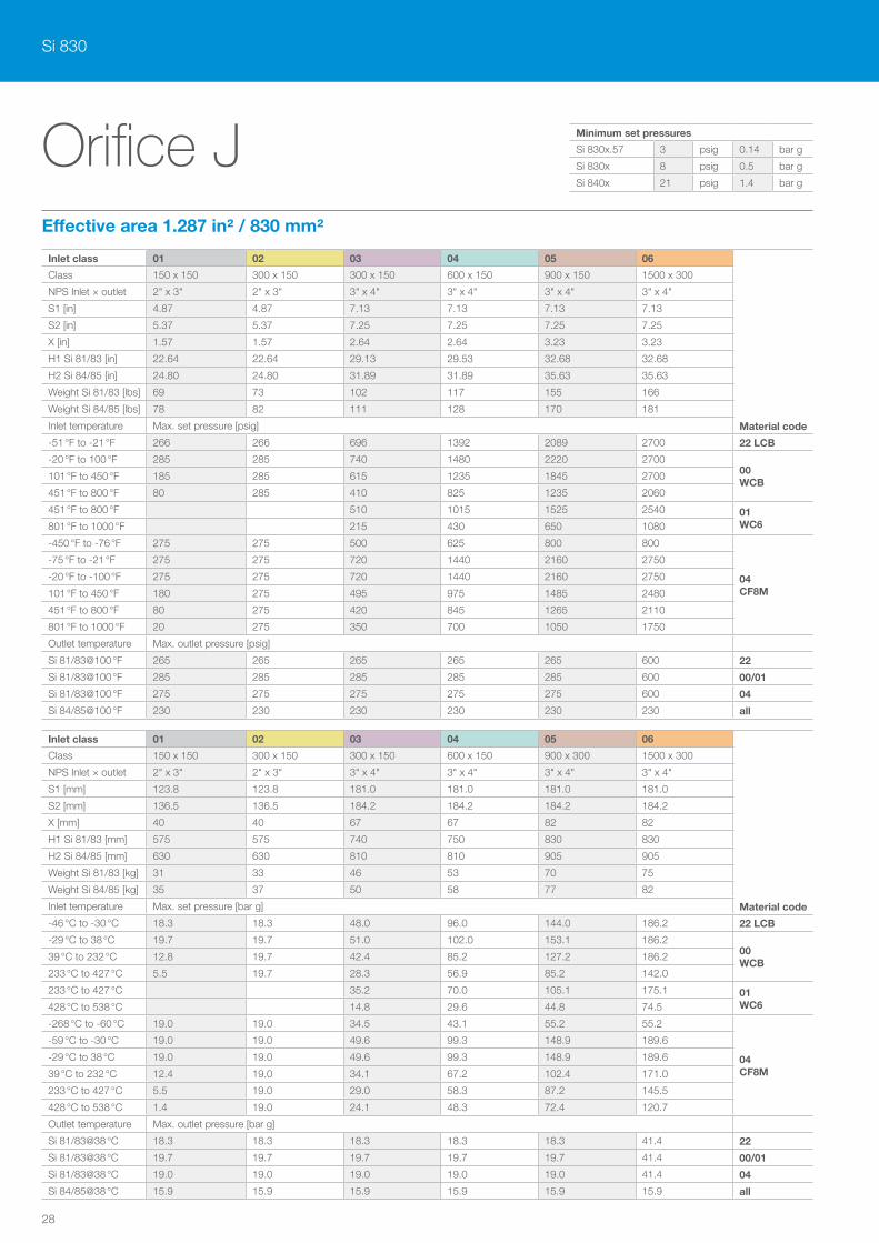
Orifice J
Inlet class 01 02 03 04 05 06
Material code
Class 150 x 150 300 x 150 300 x 150 600 x 150 900 x 150 1500 x 300
NPS Inlet × outlet 2" x 3" 2" x 3" 3" x 4" 3" x 4" 3" x 4" 3" x 4"
S1 [in] 4.87 4.87 7.13 7.13 7.13 7.13
S2 [in] 5.37 5.37 7.25 7.25 7.25 7.25
X [in] 1.57 1.57 2.64 2.64 3.23 3.23
H1 Si 81/83 [in] 22.64 22.64 29.13 29.53 32.68 32.68
H2 Si 84/85 [in] 24.80 24.80 31.89 31.89 35.63 35.63
Weight Si 81/83 [lbs] 69 73 102 117 155 166
Weight Si 84/85 [lbs] 78 82 111 128 170 181
Inlet temperature Max. set pressure [psig]
-51 °F to -21 °F 266 266 696 1392 2089 2700 22 LCB
-20 °F to 100 °F 285 285 740 1480 2220 270000 WCB
101 °F to 450 °F 185 285 615 1235 1845 2700
451 °F to 800 °F 80 285 410 825 1235 2060
451 °F to 800 °F 510 1015 1525 2540 01 WC6801 °F to 1000 °F 215 430 650 1080
-450 °F to -76 °F 275 275 500 625 800 800
04 CF8M
-75 °F to -21 °F 275 275 720 1440 2160 2750
-20 °F to -100 °F 275 275 720 1440 2160 2750
101 °F to 450 °F 180 275 495 975 1485 2480
451 °F to 800 °F 80 275 420 845 1265 2110
801 °F to 1000 °F 20 275 350 700 1050 1750
Outlet temperature Max. outlet pressure [psig]
Si 81/83@100 °F 265 265 265 265 265 600 22
Si 81/83@100 °F 285 285 285 285 285 600 00/01
Si 81/83@100 °F 275 275 275 275 275 600 04
Si 84/85@100 °F 230 230 230 230 230 230 all
Effective area 1.287 in² / 830 mm²
Inlet class 01 02 03 04 05 06
Material code
Class 150 x 150 300 x 150 300 x 150 600 x 150 900 x 300 1500 x 300
NPS Inlet × outlet 2" x 3" 2" x 3" 3" x 4" 3" x 4" 3" x 4" 3" x 4"
S1 [mm] 123.8 123.8 181.0 181.0 181.0 181.0
S2 [mm] 136.5 136.5 184.2 184.2 184.2 184.2
X [mm] 40 40 67 67 82 82
H1 Si 81/83 [mm] 575 575 740 750 830 830
H2 Si 84/85 [mm] 630 630 810 810 905 905
Weight Si 81/83 [kg] 31 33 46 53 70 75
Weight Si 84/85 [kg] 35 37 50 58 77 82
Inlet temperature Max. set pressure [bar g]
-46 °C to -30 °C 18.3 18.3 48.0 96.0 144.0 186.2 22 LCB
-29 °C to 38 °C 19.7 19.7 51.0 102.0 153.1 186.200 WCB
39 °C to 232 °C 12.8 19.7 42.4 85.2 127.2 186.2
233 °C to 427 °C 5.5 19.7 28.3 56.9 85.2 142.0
233 °C to 427 °C 35.2 70.0 105.1 175.1 01 WC6428 °C to 538 °C 14.8 29.6 44.8 74.5
-268 °C to -60 °C 19.0 19.0 34.5 43.1 55.2 55.2
04 CF8M
-59 °C to -30 °C 19.0 19.0 49.6 99.3 148.9 189.6
-29 °C to 38 °C 19.0 19.0 49.6 99.3 148.9 189.6
39 °C to 232 °C 12.4 19.0 34.1 67.2 102.4 171.0
233 °C to 427 °C 5.5 19.0 29.0 58.3 87.2 145.5
428 °C to 538 °C 1.4 19.0 24.1 48.3 72.4 120.7
Outlet temperature Max. outlet pressure [bar g]
Si 81/83@38 °C 18.3 18.3 18.3 18.3 18.3 41.4 22
Si 81/83@38 °C 19.7 19.7 19.7 19.7 19.7 41.4 00/01
Si 81/83@38 °C 19.0 19.0 19.0 19.0 19.0 41.4 04
Si 84/85@38 °C 15.9 15.9 15.9 15.9 15.9 15.9 all
Minimum set pressures
Si 830x.57 3 psig 0.14 bar g
Si 830x 8 psig 0.5 bar g
Si 840x 21 psig 1.4 bar g
29
Orifice J
0102
0304
0506
Tem
pera
tur [
°F]
Druck [psi]
0
200
400
600
800
1000
0 1000 2000
0
100
200
300
400
500
0 50 100 150
Tem
pera
tur [
°C]
Druck [bar]
Tem
pera
tur [
°F]
Druck [psi]
−400
−200
0
200
400
600
800
1000
0 1000 2000
−200
−100
0
100
200
300
400
500
0 50 100 150Te
mpe
ratu
r [°C
]Druck [bar]
0102
0304
0506
Tem
pera
tur [
°F]
Druck [psi]
0
200
400
600
800
1000
0 1000 2000
0
100
200
300
400
500
0 50 100 150
Tem
pera
tur [
°C]
Druck [bar]
Tem
pera
tur [
°F]
Druck [psi]
−400
−200
0
200
400
600
800
1000
0 1000 2000
−200
−100
0
100
200
300
400
500
0 50 100 150Te
mpe
ratu
r [°C
]
Druck [bar]
01 WC6
00 WCB
04 CF8M
Inle
t te
mp
erat
ure
[ °C
] In
let
tem
per
atur
e [ °
C]
Inle
t te
mp
erat
ure
[°F]
In
let
tem
per
atur
e [°
F]
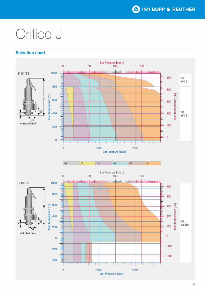
Si 81/83
S1conventional
S2
x
H1
1000
800
600
400
200
0
1000
800
600
400
200
0
-200
-400
500
400
300
200
100
0
500
400
300
200
100
0
-100
-200
Set Pressure [bar g] 0 50 100 150
0 1000 2000Set Pressure [psig]
0 1000 2000 Set Pressure [psig]
Set Pressure [bar g] 0 50 100 150
01 02 03 04 05 06
with bellows
Si 84/85
S1
S2
H2
x
Selection chart
Si 830
30
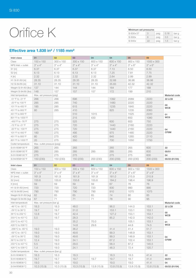
Orifice K
Inlet class 01 02 03 04 04 05 06
Material code
Class 150 x 150 300 x 150 300 x 150 600 x 150 600 x 150 900 x 150 1500 x 300NPS Inlet × outlet 3" x 4" 3" x 4" 3" x 4" 3" x 4" 3" x 4" 3" x 6" 3" x 6"S1 [in] 6.37 6.37 6.37 6.37 7.13 8.50 8.50S2 [in] 6.13 6.13 6.13 6.13 7.25 7.81 7.75X [in] 2.32 2.32 2.32 2.32 2.64 2.99 2.99H1 Si 81/83 [in] 28.35 28.35 28.35 28.35 32.68 38.98 38.98H2 Si 84/85 [in] 31.10 31.10 31.10 31.10 35.83 42.32 42.32Weight Si 81/83 [lbs] 137 144 144 144 164 177 188Weight Si 84/85 [lbs] 148 157 157 157 172 199 210Inlet temperature Max. set pressure [psig]
-51 °F to -21 °F 266 266 696 1392 2089 2220 22 LCB
-20 °F to 100 °F 285 285 740 1480 2220 222000 WCB
101 °F to 450 °F 185 285 615 1235 1845 2220451 °F to 800 °F 80 285 410 825 1235 2060451 °F to 800 °F 510 1015 1525 2220 01
WC6801 °F to 1000 °F 215 430 650 1080-450 °F to -76 °F 275 275 525 600 600 750
04 CF8M
-75 °F to -21 °F 275 275 720 1440 2160 2220-20 °F to -100 °F 275 275 720 1440 2160 2220101 °F to 450 °F 180 275 495 975 1485 2220451 °F to 800 °F 80 275 420 845 1265 2110801 °F to 1000 °F 20 275 350 700 1050 1750Outlet temperature Max. outlet pressure [psig]
Si 81/83@100 °F 265 265 265 265 265 600 22
Si 81/83@100 °F 285 285 285 285 285 285 600 00/01
Si 81/83@100 °F 275 275 275 275 275 600 04
Si 84/85@100 °F 150 (230) 150 (230) 150 (230) 200 (230) 200 (230) 200 (230) 200 (230) 00/22 (01/04)
Effective area 1.838 in² / 1185 mm²
Inlet class 01 02 03 04 04 05 06
Material code
Class 150 x 150 300 x 150 300 x 150 600 x 150 600 x 150 900 x 150 1500 x 300NPS Inlet × outlet 3" x 4" 3" x 4" 3" x 4" 3" x 4" 3" x 4" 3" x 6" 3" x 6"S1 [mm] 161.9 161.9 161.9 161.9 181.0 215.9 215.9S2 [mm] 155.6 155.6 155.6 155.6 184.2 198.4 196.9X [mm] 59 59 59 59 67 76 76H1 Si 81/83 [mm] 720 720 720 720 830 990 990H2 Si 84/85 [mm] 790 790 790 790 910 1075 1075Weight Si 81/83 [kg] 62 65 65 65 74 80 85Weight Si 84/85 [kg] 67 71 71 71 78 90 95Inlet temperature Max. set pressure [bar g]
-46 °C to -30 °C 18.3 18.3 48.0 96.0 144.0 153.1 22 LCB
-29 °C to 38 °C 19.7 19.7 51.0 153.1 153.1 153.100 WCB
39 °C to 232 °C 12.8 19.7 42.4 127.2 153.1 153.1233 °C to 427 °C 5.5 19.7 28.3 85.2 142.0 142.0233 °C to 427 °C 35.2 70.0 105.1 153.1 01
WC6428 °C to 538 °C 14.8 29.6 44.8 74.5-268 °C to -60 °C 19.0 19.0 36.2 41.4 41.4 51.7
04 CF8M
-59 °C to -30 °C 19.0 19.0 49.6 99.3 148.9 153.1-29 °C to 38 °C 19.0 19.0 49.6 99.3 148.9 153.139 °C to 232 °C 12.4 19.0 34.1 67.2 102.4 153.1233 °C to 427 °C 5.5 19.0 29.0 58.3 87.2 145.5428 °C to 538 °C 1.4 19.0 24.1 48.3 72.4 120.7Outlet temperature Max. outlet pressure [bar g]
Si 81/83@38 °C 18.3 18.3 18.3 18.3 18.3 41.4 22
Si 81/83@38 °C 19.7 19.7 19.7 19.7 19.7 19.7 41.4 00/01
Si 81/83@38 °C 19.0 19.0 19.0 19.0 19.0 41.4 04
Si 84/85@38 °C 10.3 (15.9) 10.3 (15.9) 10.3 (15.9) 13.8 (15.9) 13.8 (15.9) 13.8 (15.9) 13.8 (15.9) 00/22 (01/04)
Minimum set pressures
Si 830x.57 3 psig 0.18 bar g
Si 830x 8 psig 0.5 bar g
Si 840x 22 psig 1.5 bar g
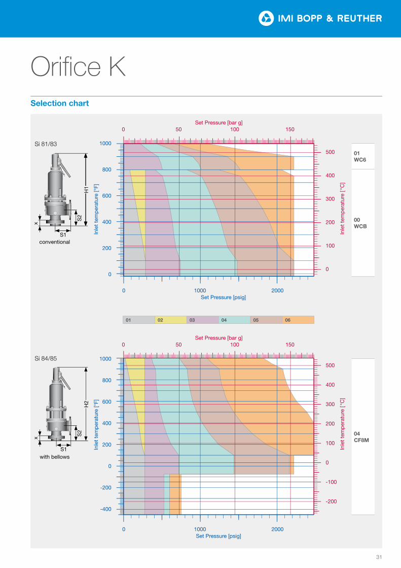
31
Orifice K
0102
0304
0506
Tem
pera
tur [
°F]
Druck [psi]
0
200
400
600
800
1000
0 1000 2000
0
100
200
300
400
500
0 50 100 150
Tem
pera
tur [
°C]
Druck [bar]
Tem
pera
tur [
°F]
Druck [psi]
−400
−200
0
200
400
600
800
1000
0 1000 2000
−200
−100
0
100
200
300
400
500
0 50 100 150Te
mpe
ratu
r [°C
]Druck [bar]
0102
0304
0506
Tem
pera
tur [
°F]
Druck [psi]
0
200
400
600
800
1000
0 1000 2000
0
100
200
300
400
500
0 50 100 150
Tem
pera
tur [
°C]
Druck [bar]
Tem
pera
tur [
°F]
Druck [psi]
−400
−200
0
200
400
600
800
1000
0 1000 2000
−200
−100
0
100
200
300
400
500
0 50 100 150Te
mpe
ratu
r [°C
]
Druck [bar]
01 WC6
00 WCB
04 CF8M
Inle
t te
mp
erat
ure
[ °C
] In
let
tem
per
atur
e [ °
C]
Inle
t te
mp
erat
ure
[°F]
In
let
tem
per
atur
e [°
F]
Si 81/83
S1conventional
S2
x
H1
1000
800
600
400
200
0
1000
800
600
400
200
0
-200
-400
500
400
300
200
100
0
500
400
300
200
100
0
-100
-200
Set Pressure [bar g] 0 50 100 150
0 1000 2000Set Pressure [psig]
0 1000 2000 Set Pressure [psig]
Set Pressure [bar g] 0 50 100 150
01 02 03 04 05 06
with bellows
Si 84/85
S1
S2
H2
x
Selection chart
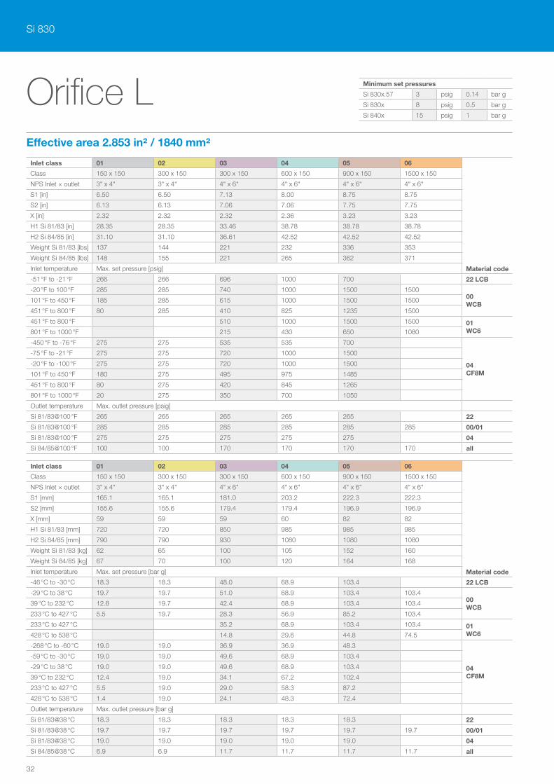
Si 830
32
Orifice LEffective area 2.853 in² / 1840 mm²
Inlet class 01 02 03 04 05 06
Material code
Class 150 x 150 300 x 150 300 x 150 600 x 150 900 x 150 1500 x 150
NPS Inlet × outlet 3" x 4" 3" x 4" 4" x 6" 4" x 6" 4" x 6" 4" x 6"
S1 [in] 6.50 6.50 7.13 8.00 8.75 8.75
S2 [in] 6.13 6.13 7.06 7.06 7.75 7.75
X [in] 2.32 2.32 2.32 2.36 3.23 3.23
H1 Si 81/83 [in] 28.35 28.35 33.46 38.78 38.78 38.78
H2 Si 84/85 [in] 31.10 31.10 36.61 42.52 42.52 42.52
Weight Si 81/83 [lbs] 137 144 221 232 336 353
Weight Si 84/85 [lbs] 148 155 221 265 362 371
Inlet temperature Max. set pressure [psig]
-51 °F to -21 °F 266 266 696 1000 700 22 LCB
-20 °F to 100 °F 285 285 740 1000 1500 150000 WCB
101 °F to 450 °F 185 285 615 1000 1500 1500
451 °F to 800 °F 80 285 410 825 1235 1500
451 °F to 800 °F 510 1000 1500 1500 01 WC6801 °F to 1000 °F 215 430 650 1080
-450 °F to -76 °F 275 275 535 535 700
04 CF8M
-75 °F to -21 °F 275 275 720 1000 1500
-20 °F to -100 °F 275 275 720 1000 1500
101 °F to 450 °F 180 275 495 975 1485
451 °F to 800 °F 80 275 420 845 1265
801 °F to 1000 °F 20 275 350 700 1050
Outlet temperature Max. outlet pressure [psig]
Si 81/83@100 °F 265 265 265 265 265 22
Si 81/83@100 °F 285 285 285 285 285 285 00/01
Si 81/83@100 °F 275 275 275 275 275 04
Si 84/85@100 °F 100 100 170 170 170 170 all
Inlet class 01 02 03 04 05 06
Material code
Class 150 x 150 300 x 150 300 x 150 600 x 150 900 x 150 1500 x 150
NPS Inlet × outlet 3" x 4" 3" x 4" 4" x 6" 4" x 6" 4" x 6" 4" x 6"
S1 [mm] 165.1 165.1 181.0 203.2 222.3 222.3
S2 [mm] 155.6 155.6 179.4 179.4 196.9 196.9
X [mm] 59 59 59 60 82 82
H1 Si 81/83 [mm] 720 720 850 985 985 985
H2 Si 84/85 [mm] 790 790 930 1080 1080 1080
Weight Si 81/83 [kg] 62 65 100 105 152 160
Weight Si 84/85 [kg] 67 70 100 120 164 168
Inlet temperature Max. set pressure [bar g]
-46 °C to -30 °C 18.3 18.3 48.0 68.9 103.4 22 LCB
-29 °C to 38 °C 19.7 19.7 51.0 68.9 103.4 103.400 WCB
39 °C to 232 °C 12.8 19.7 42.4 68.9 103.4 103.4
233 °C to 427 °C 5.5 19.7 28.3 56.9 85.2 103.4
233 °C to 427 °C 35.2 68.9 103.4 103.4 01 WC6428 °C to 538 °C 14.8 29.6 44.8 74.5
-268 °C to -60 °C 19.0 19.0 36.9 36.9 48.3
04 CF8M
-59 °C to -30 °C 19.0 19.0 49.6 68.9 103.4
-29 °C to 38 °C 19.0 19.0 49.6 68.9 103.4
39 °C to 232 °C 12.4 19.0 34.1 67.2 102.4
233 °C to 427 °C 5.5 19.0 29.0 58.3 87.2
428 °C to 538 °C 1.4 19.0 24.1 48.3 72.4
Outlet temperature Max. outlet pressure [bar g]
Si 81/83@38 °C 18.3 18.3 18.3 18.3 18.3 22
Si 81/83@38 °C 19.7 19.7 19.7 19.7 19.7 19.7 00/01
Si 81/83@38 °C 19.0 19.0 19.0 19.0 19.0 04
Si 84/85@38 °C 6.9 6.9 11.7 11.7 11.7 11.7 all
Minimum set pressures
Si 830x.57 3 psig 0.14 bar g
Si 830x 8 psig 0.5 bar g
Si 840x 15 psig 1 bar g
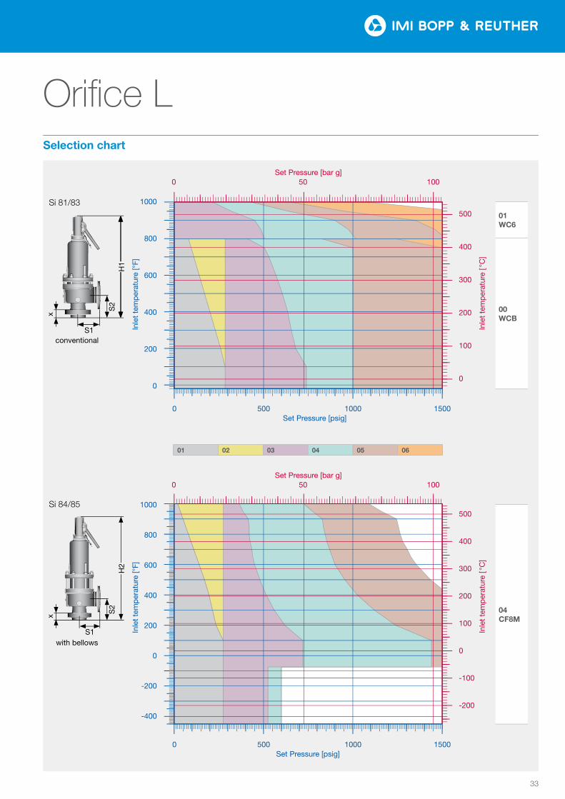
33
Orifice L
0102
0304
0506
Tem
pera
tur [
°F]
Druck [psi]
0
200
400
600
800
1000
0 500 1000 1500
0
100
200
300
400
500
0 50 100
Tem
pera
tur [
°C]
Druck [bar]
Tem
pera
tur [
°F]
Druck [psi]
−400
−200
0
200
400
600
800
1000
0 500 1000 1500
−200
−100
0
100
200
300
400
500
0 50 100Te
mpe
ratu
r [°C
]Druck [bar]
0102
0304
0506
Tem
pera
tur [
°F]
Druck [psi]
0
200
400
600
800
1000
0 500 1000 1500
0
100
200
300
400
500
0 50 100
Tem
pera
tur [
°C]
Druck [bar]
Tem
pera
tur [
°F]
Druck [psi]
−400
−200
0
200
400
600
800
1000
0 500 1000 1500
−200
−100
0
100
200
300
400
500
0 50 100Te
mpe
ratu
r [°C
]
Druck [bar]
01 WC6
00 WCB
04 CF8M
Inle
t te
mp
erat
ure
[ °C
] In
let
tem
per
atur
e [ °
C]
Inle
t te
mp
erat
ure
[°F]
In
let
tem
per
atur
e [°
F]
Si 81/83
S1conventional
S2
x
H1
1000
800
600
400
200
0
1000
800
600
400
200
0
-200
-400
500
400
300
200
100
0
500
400
300
200
100
0
-100
-200
Set Pressure [bar g] 0 50 100
0 500 1000 1500Set Pressure [psig]
0 500 1000 1500 Set Pressure [psig]
Set Pressure [bar g] 0 50 100
01 02 03 04 05 06
with bellows
Si 84/85
S1
S2
H2
x
Selection chart
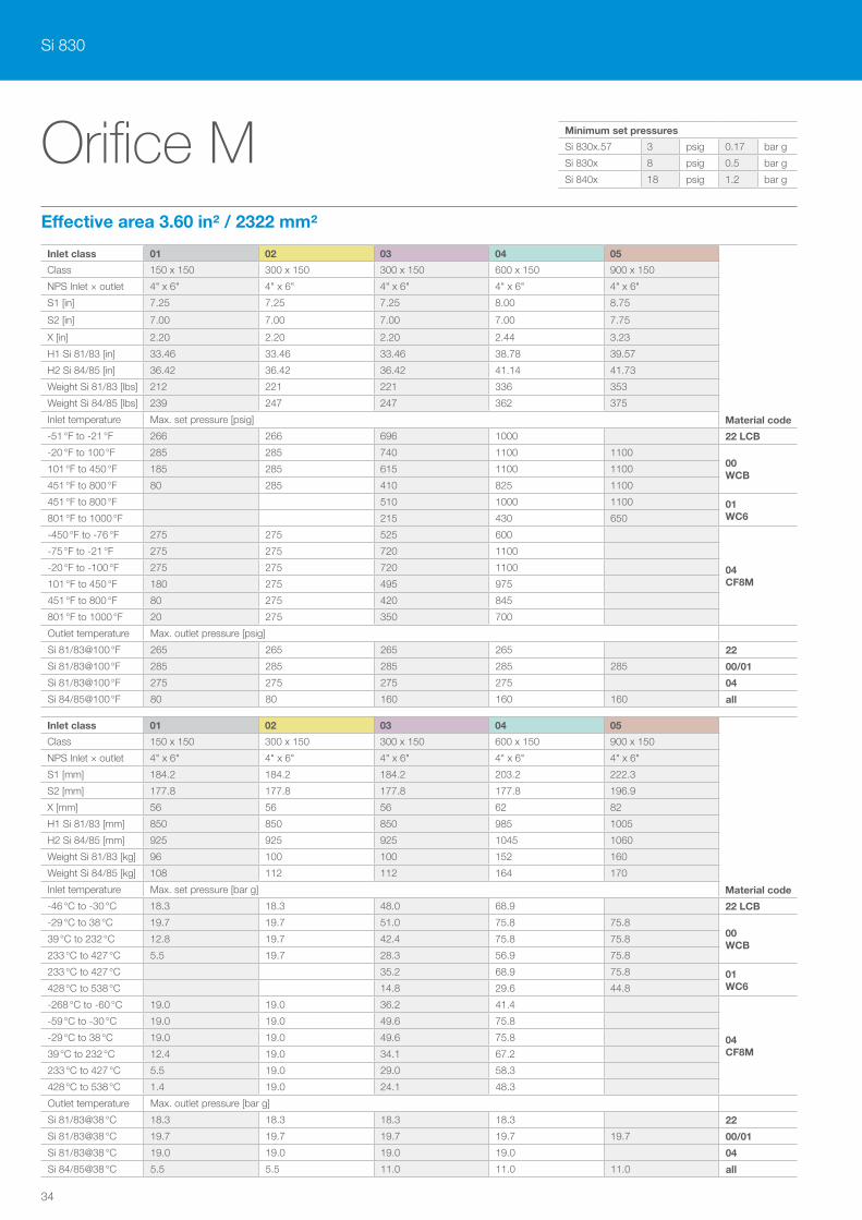
Si 830
34
Orifice MEffective area 3.60 in² / 2322 mm²
Inlet class 01 02 03 04 05
Material code
Class 150 x 150 300 x 150 300 x 150 600 x 150 900 x 150
NPS Inlet × outlet 4" x 6" 4" x 6" 4" x 6" 4" x 6" 4" x 6"
S1 [in] 7.25 7.25 7.25 8.00 8.75
S2 [in] 7.00 7.00 7.00 7.00 7.75
X [in] 2.20 2.20 2.20 2.44 3.23
H1 Si 81/83 [in] 33.46 33.46 33.46 38.78 39.57
H2 Si 84/85 [in] 36.42 36.42 36.42 41.14 41.73
Weight Si 81/83 [lbs] 212 221 221 336 353
Weight Si 84/85 [lbs] 239 247 247 362 375
Inlet temperature Max. set pressure [psig]
-51 °F to -21 °F 266 266 696 1000 22 LCB
-20 °F to 100 °F 285 285 740 1100 110000 WCB
101 °F to 450 °F 185 285 615 1100 1100
451 °F to 800 °F 80 285 410 825 1100
451 °F to 800 °F 510 1000 1100 01 WC6801 °F to 1000 °F 215 430 650
-450 °F to -76 °F 275 275 525 600
04 CF8M
-75 °F to -21 °F 275 275 720 1100
-20 °F to -100 °F 275 275 720 1100
101 °F to 450 °F 180 275 495 975
451 °F to 800 °F 80 275 420 845
801 °F to 1000 °F 20 275 350 700
Outlet temperature Max. outlet pressure [psig]
Si 81/83@100 °F 265 265 265 265 22
Si 81/83@100 °F 285 285 285 285 285 00/01
Si 81/83@100 °F 275 275 275 275 04
Si 84/85@100 °F 80 80 160 160 160 all
Inlet class 01 02 03 04 05
Material code
Class 150 x 150 300 x 150 300 x 150 600 x 150 900 x 150
NPS Inlet × outlet 4" x 6" 4" x 6" 4" x 6" 4" x 6" 4" x 6"
S1 [mm] 184.2 184.2 184.2 203.2 222.3
S2 [mm] 177.8 177.8 177.8 177.8 196.9
X [mm] 56 56 56 62 82
H1 Si 81/83 [mm] 850 850 850 985 1005
H2 Si 84/85 [mm] 925 925 925 1045 1060
Weight Si 81/83 [kg] 96 100 100 152 160
Weight Si 84/85 [kg] 108 112 112 164 170
Inlet temperature Max. set pressure [bar g]
-46 °C to -30 °C 18.3 18.3 48.0 68.9 22 LCB
-29 °C to 38 °C 19.7 19.7 51.0 75.8 75.800 WCB
39 °C to 232 °C 12.8 19.7 42.4 75.8 75.8
233 °C to 427 °C 5.5 19.7 28.3 56.9 75.8
233 °C to 427 °C 35.2 68.9 75.8 01 WC6428 °C to 538 °C 14.8 29.6 44.8
-268 °C to -60 °C 19.0 19.0 36.2 41.4
04 CF8M
-59 °C to -30 °C 19.0 19.0 49.6 75.8
-29 °C to 38 °C 19.0 19.0 49.6 75.8
39 °C to 232 °C 12.4 19.0 34.1 67.2
233 °C to 427 °C 5.5 19.0 29.0 58.3
428 °C to 538 °C 1.4 19.0 24.1 48.3
Outlet temperature Max. outlet pressure [bar g]
Si 81/83@38 °C 18.3 18.3 18.3 18.3 22
Si 81/83@38 °C 19.7 19.7 19.7 19.7 19.7 00/01
Si 81/83@38 °C 19.0 19.0 19.0 19.0 04
Si 84/85@38 °C 5.5 5.5 11.0 11.0 11.0 all
Minimum set pressures
Si 830x.57 3 psig 0.17 bar g
Si 830x 8 psig 0.5 bar g
Si 840x 18 psig 1.2 bar g
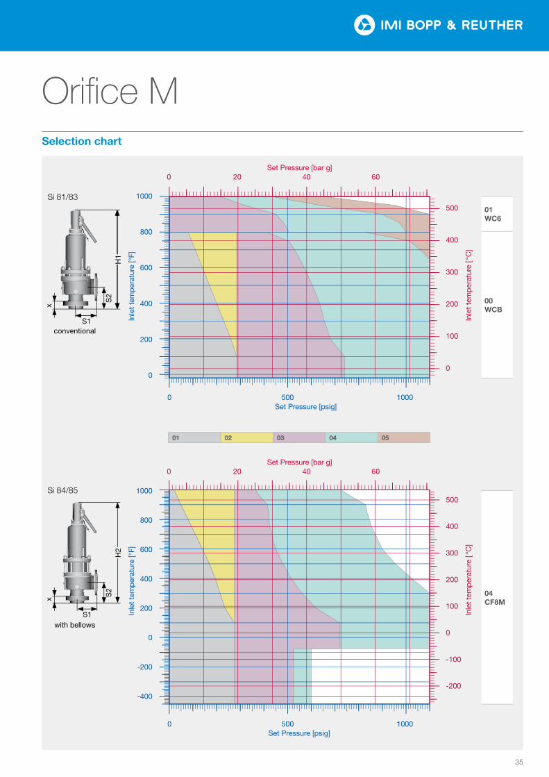
35
Orifice M
0102
0304
05
Tem
pera
tur [
°F]
Druck [psi]
0
200
400
600
800
1000
0 500 1000
0
100
200
300
400
500
0 20 40 60
Tem
pera
tur [
°C]
Druck [bar]
Tem
pera
tur [
°F]
Druck [psi]
−400
−200
0
200
400
600
800
1000
0 500 1000
−200
−100
0
100
200
300
400
500
0 20 40 60Te
mpe
ratu
r [°C
]Druck [bar]
0102
0304
05
Tem
pera
tur [
°F]
Druck [psi]
0
200
400
600
800
1000
0 500 1000
0
100
200
300
400
500
0 20 40 60
Tem
pera
tur [
°C]
Druck [bar]
Tem
pera
tur [
°F]
Druck [psi]
−400
−200
0
200
400
600
800
1000
0 500 1000
−200
−100
0
100
200
300
400
500
0 20 40 60Te
mpe
ratu
r [°C
]
Druck [bar]
01 WC6
00 WCB
04 CF8M
Inle
t te
mp
erat
ure
[ °C
] In
let
tem
per
atur
e [ °
C]
Inle
t te
mp
erat
ure
[°F]
In
let
tem
per
atur
e [°
F]
Si 81/83
S1conventional
S2
x
H1
1000
800
600
400
200
0
1000
800
600
400
200
0
-200
-400
500
400
300
200
100
0
500
400
300
200
100
0
-100
-200
Set Pressure [bar g] 0 20 40 60
0 500 1000 Set Pressure [psig]
0 500 1000 Set Pressure [psig]
Set Pressure [bar g] 0 20 40 60
01 02 03 04 05
with bellows
Si 84/85
S1
S2
H2
x
Selection chart
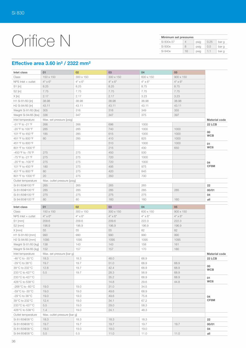
Si 830
36
Orifice NEffective area 3.60 in² / 2322 mm²
Inlet class 01 02 03 04 05
Material code
Class 150 x 150 300 x 150 300 x 150 600 x 150 900 x 150
NPS Inlet × outlet 4" x 6" 4" x 6" 4" x 6" 4" x 6" 4" x 6"
S1 [in] 8.25 8.25 8.25 8.75 8.75
S2 [in] 7.75 7.75 7.75 7.75 7.75
X [in] 2.17 2.17 2.17 3.23 3.23
H1 Si 81/83 [in] 38.98 38.98 38.98 38.98 38.98
H2 Si 84/85 [in] 43.11 43.11 43.11 43.11 43.11
Weight Si 81/83 [lbs] 305 316 316 349 355
Weight Si 84/85 [lbs] 336 347 347 375 397
Inlet temperature Max. set pressure [psig]
-51 °F to -21 °F 266 266 696 1000 22 LCB
-20 °F to 100 °F 285 285 740 1000 100000 WCB
101 °F to 450 °F 185 285 615 1000 1000
451 °F to 800 °F 80 285 410 825 1000
451 °F to 800 °F 510 1000 1000 01 WC6801 °F to 1000 °F 215 430 650
-450 °F to -76 °F 275 275 450 500
04 CF8M
-75 °F to -21 °F 275 275 720 1000
-20 °F to -100 °F 275 275 720 1000
101 °F to 450 °F 180 275 495 975
451 °F to 800 °F 80 275 420 845
801 °F to 1000 °F 20 275 350 700
Outlet temperature Max. outlet pressure [psig]
Si 81/83@100 °F 265 265 265 265 22
Si 81/83@100 °F 285 285 285 285 285 00/01
Si 81/83@100 °F 275 275 275 275 04
Si 84/85@100 °F 80 80 160 160 160 all
Inlet class 01 02 03 04 05
Material code
Class 150 x 150 300 x 150 300 x 150 600 x 150 900 x 150
NPS Inlet × outlet 4" x 6" 4" x 6" 4" x 6" 4" x 6" 4" x 6"
S1 [mm] 209.6 209.6 209.6 222.3 222.3
S2 [mm] 196.9 196.9 196.9 196.9 196.9
X [mm] 55 55 55 82 82
H1 Si 81/83 [mm] 990 990 990 990 990
H2 Si 84/85 [mm] 1095 1095 1095 1095 1095
Weight Si 81/83 [kg] 138 143 143 158 161
Weight Si 84/85 [kg] 152 157 157 170 180
Inlet temperature Max. set pressure [bar g]
-46 °C to -30 °C 18.3 18.3 48.0 68.9 22 LCB
-29 °C to 38 °C 19.7 19.7 51.0 68.9 68.900 WCB
39 °C to 232 °C 12.8 19.7 42.4 68.9 68.9
233 °C to 427 °C 5.5 19.7 28.3 56.9 68.9
233 °C to 427 °C 35.2 68.9 68.9 01 WC6428 °C to 538 °C 14.8 29.6 44.8
-268 °C to -60 °C 19.0 19.0 31.0 34.5
04 CF8M
-59 °C to -30 °C 19.0 19.0 49.6 68.9
-29 °C to 38 °C 19.0 19.0 49.6 75.8
39 °C to 232 °C 12.4 19.0 34.1 67.2
233 °C to 427 °C 5.5 19.0 29.0 58.3
428 °C to 538 °C 1.4 19.0 24.1 48.3
Outlet temperature Max. outlet pressure [bar g]
Si 81/83@38 °C 18.3 18.3 18.3 18.3 22
Si 81/83@38 °C 19.7 19.7 19.7 19.7 19.7 00/01
Si 81/83@38 °C 19.0 19.0 19.0 19.0 04
Si 84/85@38 °C 5.5 5.5 11.0 11.0 11.0 all
Minimum set pressures
Si 830x.57 4 psig 0.25 bar g
Si 830x 8 psig 0.5 bar g
Si 840x 16 psig 1.1 bar g
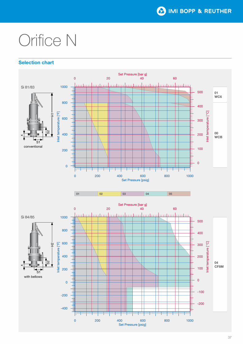
37
Orifice N
0102
0304
05
Tem
pera
tur [
°F]
Druck [psi]
0
200
400
600
800
1000
0 200 400 600 800 1000
0
100
200
300
400
500
0 20 40 60
Tem
pera
tur [
°C]
Druck [bar]
Tem
pera
tur [
°F]
Druck [psi]
−400
−200
0
200
400
600
800
1000
0 200 400 600 800 1000
−200
−100
0
100
200
300
400
500
0 20 40 60Te
mpe
ratu
r [°C
]Druck [bar]
0102
0304
05
Tem
pera
tur [
°F]
Druck [psi]
0
200
400
600
800
1000
0 200 400 600 800 1000
0
100
200
300
400
500
0 20 40 60
Tem
pera
tur [
°C]
Druck [bar]
Tem
pera
tur [
°F]
Druck [psi]
−400
−200
0
200
400
600
800
1000
0 200 400 600 800 1000
−200
−100
0
100
200
300
400
500
0 20 40 60Te
mpe
ratu
r [°C
]
Druck [bar]
01 WC6
00 WCB
04 CF8M
Inle
t te
mp
erat
ure
[ °C
] In
let
tem
per
atur
e [ °
C]
Inle
t te
mp
erat
ure
[°F]
In
let
tem
per
atur
e [°
F]
Si 81/83
S1conventional
S2
x
H1
1000
800
600
400
200
0
1000
800
600
400
200
0
-200
-400
500
400
300
200
100
0
500
400
300
200
100
0
-100
-200
Set Pressure [bar g] 0 20 40 60
0 200 400 600 800 1000Set Pressure [psig]
0 200 400 600 800 1000 Set Pressure [psig]
Set Pressure [bar g] 0 20 40 60
01 02 03 04 05
with bellows
Si 84/85
S1
S2
H2
x
Selection chart
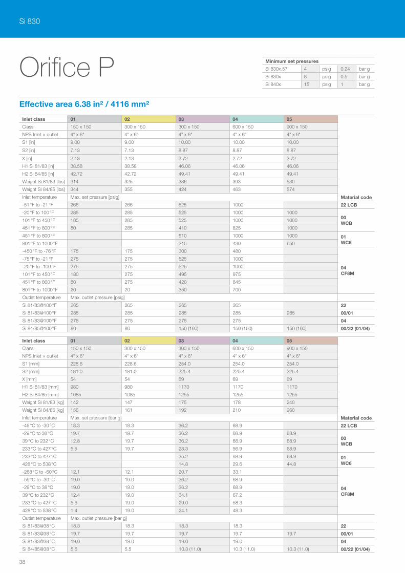
Si 830
38
Orifice PEffective area 6.38 in² / 4116 mm²
Inlet class 01 02 03 04 05
Material code
Class 150 x 150 300 x 150 300 x 150 600 x 150 900 x 150
NPS Inlet × outlet 4" x 6" 4" x 6" 4" x 6" 4" x 6" 4" x 6"
S1 [in] 9.00 9.00 10.00 10.00 10.00
S2 [in] 7.13 7.13 8.87 8.87 8.87
X [in] 2.13 2.13 2.72 2.72 2.72
H1 Si 81/83 [in] 38.58 38.58 46.06 46.06 46.06
H2 Si 84/85 [in] 42.72 42.72 49.41 49.41 49.41
Weight Si 81/83 [lbs] 314 325 386 393 530
Weight Si 84/85 [lbs] 344 355 424 463 574
Inlet temperature Max. set pressure [psig]
-51 °F to -21 °F 266 266 525 1000 22 LCB
-20 °F to 100 °F 285 285 525 1000 100000 WCB
101 °F to 450 °F 185 285 525 1000 1000
451 °F to 800 °F 80 285 410 825 1000
451 °F to 800 °F 510 1000 1000 01 WC6801 °F to 1000 °F 215 430 650
-450 °F to -76 °F 175 175 300 480
04 CF8M
-75 °F to -21 °F 275 275 525 1000
-20 °F to -100 °F 275 275 525 1000
101 °F to 450 °F 180 275 495 975
451 °F to 800 °F 80 275 420 845
801 °F to 1000 °F 20 20 350 700
Outlet temperature Max. outlet pressure [psig]
Si 81/83@100 °F 265 265 265 265 22
Si 81/83@100 °F 285 285 285 285 285 00/01
Si 81/83@100 °F 275 275 275 275 04
Si 84/85@100 °F 80 80 150 (160) 150 (160) 150 (160) 00/22 (01/04)
Inlet class 01 02 03 04 05
Material code
Class 150 x 150 300 x 150 300 x 150 600 x 150 900 x 150
NPS Inlet × outlet 4" x 6" 4" x 6" 4" x 6" 4" x 6" 4" x 6"
S1 [mm] 228.6 228.6 254.0 254.0 254.0
S2 [mm] 181.0 181.0 225.4 225.4 225.4
X [mm] 54 54 69 69 69
H1 Si 81/83 [mm] 980 980 1170 1170 1170
H2 Si 84/85 [mm] 1085 1085 1255 1255 1255
Weight Si 81/83 [kg] 142 147 175 178 240
Weight Si 84/85 [kg] 156 161 192 210 260
Inlet temperature Max. set pressure [bar g]
-46 °C to -30 °C 18.3 18.3 36.2 68.9 22 LCB
-29 °C to 38 °C 19.7 19.7 36.2 68.9 68.900 WCB
39 °C to 232 °C 12.8 19.7 36.2 68.9 68.9
233 °C to 427 °C 5.5 19.7 28.3 56.9 68.9
233 °C to 427 °C 35.2 68.9 68.9 01 WC6428 °C to 538 °C 14.8 29.6 44.8
-268 °C to -60 °C 12.1 12.1 20.7 33.1
04 CF8M
-59 °C to -30 °C 19.0 19.0 36.2 68.9
-29 °C to 38 °C 19.0 19.0 36.2 68.9
39 °C to 232 °C 12.4 19.0 34.1 67.2
233 °C to 427 °C 5.5 19.0 29.0 58.3
428 °C to 538 °C 1.4 19.0 24.1 48.3
Outlet temperature Max. outlet pressure [bar g]
Si 81/83@38 °C 18.3 18.3 18.3 18.3 22
Si 81/83@38 °C 19.7 19.7 19.7 19.7 19.7 00/01
Si 81/83@38 °C 19.0 19.0 19.0 19.0 04
Si 84/85@38 °C 5.5 5.5 10.3 (11.0) 10.3 (11.0) 10.3 (11.0) 00/22 (01/04)
Minimum set pressures
Si 830x.57 4 psig 0.24 bar g
Si 830x 8 psig 0.5 bar g
Si 840x 15 psig 1 bar g
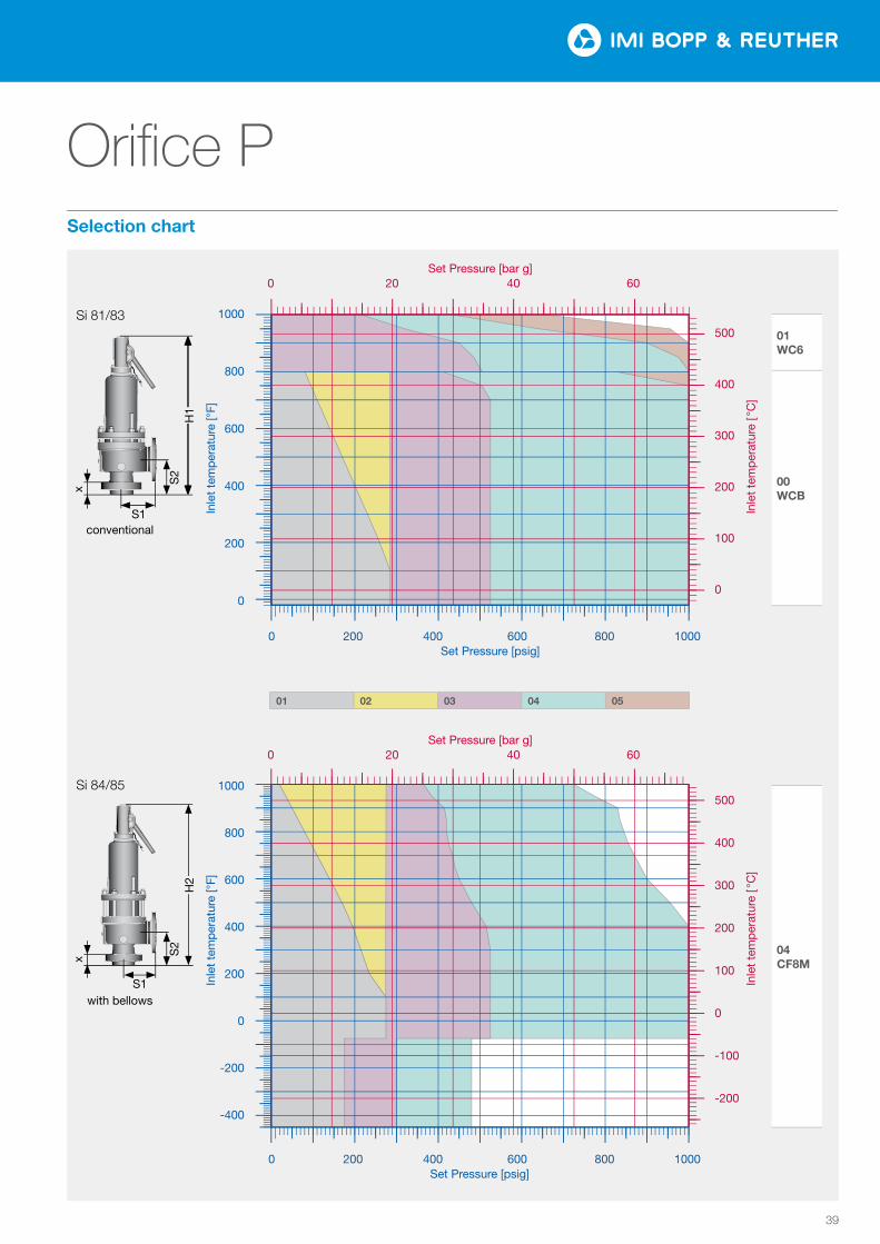
39
Orifice P
0102
0304
05
Tem
pera
tur [
°F]
Druck [psi]
0
200
400
600
800
1000
0 200 400 600 800 1000
0
100
200
300
400
500
0 20 40 60
Tem
pera
tur [
°C]
Druck [bar]
Tem
pera
tur [
°F]
Druck [psi]
−400
−200
0
200
400
600
800
1000
0 200 400 600 800 1000
−200
−100
0
100
200
300
400
500
0 20 40 60Te
mpe
ratu
r [°C
]Druck [bar]
0102
0304
05
Tem
pera
tur [
°F]
Druck [psi]
0
200
400
600
800
1000
0 200 400 600 800 1000
0
100
200
300
400
500
0 20 40 60
Tem
pera
tur [
°C]
Druck [bar]
Tem
pera
tur [
°F]
Druck [psi]
−400
−200
0
200
400
600
800
1000
0 200 400 600 800 1000
−200
−100
0
100
200
300
400
500
0 20 40 60Te
mpe
ratu
r [°C
]
Druck [bar]
01 WC6
00 WCB
04 CF8M
Inle
t te
mp
erat
ure
[ °C
] In
let
tem
per
atur
e [ °
C]
Inle
t te
mp
erat
ure
[°F]
In
let
tem
per
atur
e [°
F]
Si 81/83
S1conventional
S2
x
H1
1000
800
600
400
200
0
1000
800
600
400
200
0
-200
-400
500
400
300
200
100
0
500
400
300
200
100
0
-100
-200
Set Pressure [bar g] 0 20 40 60
0 200 400 600 800 1000Set Pressure [psig]
0 200 400 600 800 1000 Set Pressure [psig]
Set Pressure [bar g] 0 20 40 60
01 02 03 04 05
with bellows
Si 84/85
S1
S2
H2
x
Selection chart

Si 830
40
Orifice QEffective area 11.05 in² / 7129 mm²
Inlet class 01 02 03 04
Material code
Class 150 x 150 300 x 150 300 x 150 600 x 150
NPS Inlet × outlet 6" x 8" 6" x 8" 6" x 8" 6" x 8"
S1 [in] 9.50 9.50 9.50 9.50
S2 [in] 9.44 9.44 9.44 9.44
X [in] 2.36 2.36 2.36 3.07
H1 Si 81/83 [in] 46.26 46.26 46.26 46.85
H2 Si 84/85 [in] 51.38 51.38 51.38 52.17
Weight Si 81/83 [lbs] 463 486 486 640
Weight Si 84/85 [lbs] 497 508 508 684
Inlet temperature Max. set pressure [psig]
-51 °F to -21 °F 165 165 300 600 22 LCB
-20 °F to 100 °F 165 165 300 60000 WCB
101 °F to 450 °F 165 165 300 600
451 °F to 800 °F 80 165 300 600
451 °F to 800 °F 165 600 01 WC6801 °F to 1000 °F 165 430
-450 °F to -76 °F 165 165 250 300
04 CF8M
-75 °F to -21 °F 165 165 300 600
-20 °F to -100 °F 165 165 300 600
101 °F to 450 °F 165 165 300 600
451 °F to 800 °F 80 165 300 600
801 °F to 1000 °F 20 165 300 600
Outlet temperature Max. outlet pressure [psig]
Si 81/83@100 °F 115 115 115 115 22
Si 81/83@100 °F 115 115 115 115 00/01
Si 81/83@100 °F 115 115 115 115 04
Si 84/85@100 °F 70 70 115 115 all
Inlet class 01 02 03 04
Material code
Class 150 x 150 300 x 150 300 x 150 600 x 150
NPS Inlet × outlet 6" x 8" 6" x 8" 6" x 8" 6" x 8"
S1 [mm] 241.3 241.3 241.3 241.3
S2 [mm] 239.7 239.7 239.7 239.7
X [mm] 60 60 60 78
H1 Si 81/83 [mm] 1175 1175 1175 1190
H2 Si 84/85 [mm] 1305 1305 1305 1325
Weight Si 81/83 [kg] 210 220 220 290
Weight Si 84/85 [kg] 225 230 230 310
Inlet temperature Max. set pressure [bar g]
-46 °C to -30 °C 11.4 11.4 20.7 41.4 22 LCB
-29 °C to 38 °C 11.4 11.4 20.7 41.400 WCB
39 °C to 232 °C 11.4 11.4 20.7 41.4
233 °C to 427 °C 5.5 11.4 20.7 41.4
233 °C to 427 °C 11.4 41.4 01 WC6428 °C to 538 °C 11.4 29.6
-268 °C to -60 °C 11.4 11.4 17.2 20.7
04 CF8M
-59 °C to -30 °C 11.4 11.4 20.7 41.4
-29 °C to 38 °C 11.4 11.4 20.7 41.4
39 °C to 232 °C 11.4 11.4 20.7 41.4
233 °C to 427 °C 5.5 11.4 20.7 41.4
428 °C to 538 °C 1.4 11.4 20.7 41.4
Outlet temperature Max. outlet pressure [bar g]
Si 81/83@38 °C 7.9 7.9 7.9 7.9 22
Si 81/83@38 °C 7.9 7.9 7.9 7.9 00/01
Si 81/83@38 °C 7.9 7.9 7.9 7.9 04
Si 84/85@38 °C 4.8 4.8 7.9 7.9 all
Minimum set pressures
Si 830x.57 3 psig 0.18 bar g
Si 830x 8 psig 0.5 bar g
Si 840x 28 psig 1.9 bar g
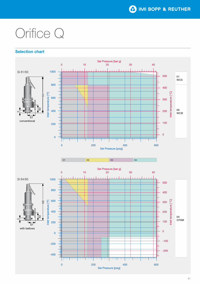
41
Orifice Q
01 02 03 04
Tem
pera
tur [
°F]
Druck [psi]
0
200
400
600
800
1000
0 200 400 600
0
100
200
300
400
500
0 10 20 30 40
Tem
pera
tur [
°C]
Druck [bar]
Tem
pera
tur [
°F]
Druck [psi]
−400
−200
0
200
400
600
800
1000
0 200 400 600
−200
−100
0
100
200
300
400
500
0 10 20 30 40Te
mpe
ratu
r [°C
]Druck [bar]
01 02 03 04
Tem
pera
tur [
°F]
Druck [psi]
0
200
400
600
800
1000
0 200 400 600
0
100
200
300
400
500
0 10 20 30 40
Tem
pera
tur [
°C]
Druck [bar]
Tem
pera
tur [
°F]
Druck [psi]
−400
−200
0
200
400
600
800
1000
0 200 400 600
−200
−100
0
100
200
300
400
500
0 10 20 30 40Te
mpe
ratu
r [°C
]
Druck [bar]
01 WC6
00 WCB
04 CF8M
Inle
t te
mp
erat
ure
[ °C
] In
let
tem
per
atur
e [ °
C]
Inle
t te
mp
erat
ure
[°F]
In
let
tem
per
atur
e [°
F]
Si 81/83
S1conventional
S2
x
H1
1000
800
600
400
200
0
1000
800
600
400
200
0
-200
-400
500
400
300
200
100
0
500
400
300
200
100
0
-100
-200
Set Pressure [bar g] 0 10 20 30 40
0 200 400 600Set Pressure [psig]
0 200 400 600 Set Pressure [psig]
Set Pressure [bar g] 0 10 20 30 40
01 02 03 04
with bellows
Si 84/85
S1
S2
H2
x
Selection chart
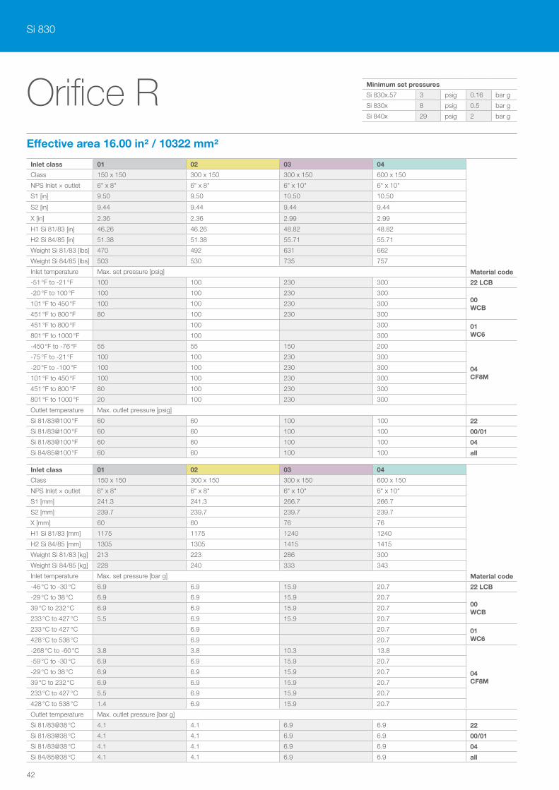
Si 830
42
Orifice REffective area 16.00 in² / 10322 mm²
Inlet class 01 02 03 04
Material code
Class 150 x 150 300 x 150 300 x 150 600 x 150
NPS Inlet × outlet 6" x 8" 6" x 8" 6" x 10" 6" x 10"
S1 [in] 9.50 9.50 10.50 10.50
S2 [in] 9.44 9.44 9.44 9.44
X [in] 2.36 2.36 2.99 2.99
H1 Si 81/83 [in] 46.26 46.26 48.82 48.82
H2 Si 84/85 [in] 51.38 51.38 55.71 55.71
Weight Si 81/83 [lbs] 470 492 631 662
Weight Si 84/85 [lbs] 503 530 735 757
Inlet temperature Max. set pressure [psig]
-51 °F to -21 °F 100 100 230 300 22 LCB
-20 °F to 100 °F 100 100 230 30000 WCB
101 °F to 450 °F 100 100 230 300
451 °F to 800 °F 80 100 230 300
451 °F to 800 °F 100 300 01 WC6801 °F to 1000 °F 100 300
-450 °F to -76 °F 55 55 150 200
04 CF8M
-75 °F to -21 °F 100 100 230 300
-20 °F to -100 °F 100 100 230 300
101 °F to 450 °F 100 100 230 300
451 °F to 800 °F 80 100 230 300
801 °F to 1000 °F 20 100 230 300
Outlet temperature Max. outlet pressure [psig]
Si 81/83@100 °F 60 60 100 100 22
Si 81/83@100 °F 60 60 100 100 00/01
Si 81/83@100 °F 60 60 100 100 04
Si 84/85@100 °F 60 60 100 100 all
Inlet class 01 02 03 04
Material code
Class 150 x 150 300 x 150 300 x 150 600 x 150
NPS Inlet × outlet 6" x 8" 6" x 8" 6" x 10" 6" x 10"
S1 [mm] 241.3 241.3 266.7 266.7
S2 [mm] 239.7 239.7 239.7 239.7
X [mm] 60 60 76 76
H1 Si 81/83 [mm] 1175 1175 1240 1240
H2 Si 84/85 [mm] 1305 1305 1415 1415
Weight Si 81/83 [kg] 213 223 286 300
Weight Si 84/85 [kg] 228 240 333 343
Inlet temperature Max. set pressure [bar g]
-46 °C to -30 °C 6.9 6.9 15.9 20.7 22 LCB
-29 °C to 38 °C 6.9 6.9 15.9 20.700 WCB
39 °C to 232 °C 6.9 6.9 15.9 20.7
233 °C to 427 °C 5.5 6.9 15.9 20.7
233 °C to 427 °C 6.9 20.7 01 WC6428 °C to 538 °C 6.9 20.7
-268 °C to -60 °C 3.8 3.8 10.3 13.8
04 CF8M
-59 °C to -30 °C 6.9 6.9 15.9 20.7
-29 °C to 38 °C 6.9 6.9 15.9 20.7
39 °C to 232 °C 6.9 6.9 15.9 20.7
233 °C to 427 °C 5.5 6.9 15.9 20.7
428 °C to 538 °C 1.4 6.9 15.9 20.7
Outlet temperature Max. outlet pressure [bar g]
Si 81/83@38 °C 4.1 4.1 6.9 6.9 22
Si 81/83@38 °C 4.1 4.1 6.9 6.9 00/01
Si 81/83@38 °C 4.1 4.1 6.9 6.9 04
Si 84/85@38 °C 4.1 4.1 6.9 6.9 all
Minimum set pressures
Si 830x.57 3 psig 0.16 bar g
Si 830x 8 psig 0.5 bar g
Si 840x 29 psig 2 bar g
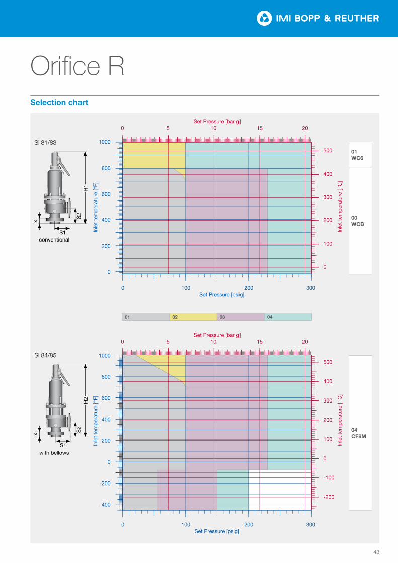
43
Orifice R
01 02 03 04
Tem
pera
tur [
°F]
Druck [psi]
0
200
400
600
800
1000
0 100 200 300
0
100
200
300
400
500
0 5 10 15 20
Tem
pera
tur [
°C]
Druck [bar]
Tem
pera
tur [
°F]
Druck [psi]
−400
−200
0
200
400
600
800
1000
0 100 200 300
−200
−100
0
100
200
300
400
500
0 5 10 15 20Te
mpe
ratu
r [°C
]Druck [bar]
01 02 03 04
Tem
pera
tur [
°F]
Druck [psi]
0
200
400
600
800
1000
0 100 200 300
0
100
200
300
400
500
0 5 10 15 20
Tem
pera
tur [
°C]
Druck [bar]
Tem
pera
tur [
°F]
Druck [psi]
−400
−200
0
200
400
600
800
1000
0 100 200 300
−200
−100
0
100
200
300
400
500
0 5 10 15 20Te
mpe
ratu
r [°C
]
Druck [bar]
01 WC6
00 WCB
04 CF8M
Inle
t te
mp
erat
ure
[ °C
] In
let
tem
per
atur
e [ °
C]
Inle
t te
mp
erat
ure
[°F]
In
let
tem
per
atur
e [°
F]
Si 81/83
S1conventional
S2
x
H1
1000
800
600
400
200
0
1000
800
600
400
200
0
-200
-400
500
400
300
200
100
0
500
400
300
200
100
0
-100
-200
Set Pressure [bar g] 0 5 10 15 20
0 100 200 300Set Pressure [psig]
0 100 200 300 Set Pressure [psig]
Set Pressure [bar g] 0 5 10 15 20
01 02 03 04
with bellows
Si 84/85
S1
S2
H2
x
Selection chart
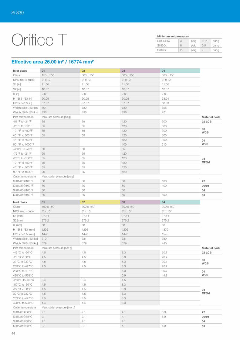
Si 830
44
Orifice TEffective area 26.00 in² / 16774 mm²
Inlet class 01 02 03 04
Material code
Class 150 x 150 300 x 150 300 x 150 300 x 150
NPS Inlet × outlet 8" x 10" 8" x 10" 8" x 10" 8" x 10"
S1 [in] 11.00 11.00 11.00 11.00
S2 [in] 10.87 10.87 10.87 10.87
X [in] 2.68 2.68 2.68 2.68
H1 Si 81/83 [in] 50.98 50.98 50.98 53.94
H2 Si 84/85 [in] 57.87 57.87 57.87 60.83
Weight Si 81/83 [lbs] 704 730 730 858
Weight Si 84/85 [lbs] 836 836 836 971
Inlet temperature Max. set pressure [psig]
-51 °F to -21 °F 65 65 120 300 22 LCB
-20 °F to 100 °F 65 65 120 30000 WCB
101 °F to 450 °F 65 65 120 300
451 °F to 800 °F 65 65 120 300
451 °F to 800 °F 120 300 01 WC6801 °F to 1000 °F 100 215
-450 °F to -76 °F 50 50 65
04 CF8M
-75 °F to -21 °F 65 65 120
-20 °F to -100 °F 65 65 120
101 °F to 450 °F 65 65 120
451 °F to 800 °F 65 65 120
801 °F to 1000 °F 20 65 120
Outlet temperature Max. outlet pressure [psig]
Si 81/83@100 °F 30 30 60 100 22
Si 81/83@100 °F 30 30 60 100 00/01
Si 81/83@100 °F 30 30 60 04
Si 84/85@100 °F 30 30 60 100 all
Inlet class 01 02 03 04
Material code
Class 150 x 150 300 x 150 300 x 150 300 x 150
NPS Inlet × outlet 8" x 10" 8" x 10" 8" x 10" 8" x 10"
S1 [mm] 279.4 279.4 279.4 279.4
S2 [mm] 276.2 276.2 276.2 276.2
X [mm] 68 68 68 68
H1 Si 81/83 [mm] 1295 1295 1295 1370
H2 Si 84/85 [mm] 1470 1470 1470 1545
Weight Si 81/83 [kg] 319 331 331 389
Weight Si 84/85 [kg] 379 379 379 440
Inlet temperature Max. set pressure [bar g]
-46 °C to -30 °C 4.5 4.5 8.3 20.7 22 LCB
-29 °C to 38 °C 4.5 4.5 8.3 20.700 WCB
39 °C to 232 °C 4.5 4.5 8.3 20.7
233 °C to 427 °C 4.5 4.5 8.3 20.7
233 °C to 427 °C 8.3 20.7 01 WC6428 °C to 538 °C 6.9 14.8
-268 °C to -60 °C 3.4 3.4 4.5
04 CF8M
-59 °C to -30 °C 4.5 4.5 8.3
-29 °C to 38 °C 4.5 4.5 8.3
39 °C to 232 °C 4.5 4.5 8.3
233 °C to 427 °C 4.5 4.5 8.3
428 °C to 538 °C 1.4 1.4 8.3
Outlet temperature Max. outlet pressure [bar g]
Si 81/83@38 °C 2.1 2.1 4.1 6.9 22
Si 81/83@38 °C 2.1 2.1 4.1 6.9 00/01
Si 81/83@38 °C 2.1 2.1 4.1 04
Si 84/85@38 °C 2.1 2.1 4.1 6.9 all
Minimum set pressures
Si 830x.57 3 psig 0.15 bar g
Si 830x 8 psig 0.5 bar g
Si 840x 29 psig 2 bar g
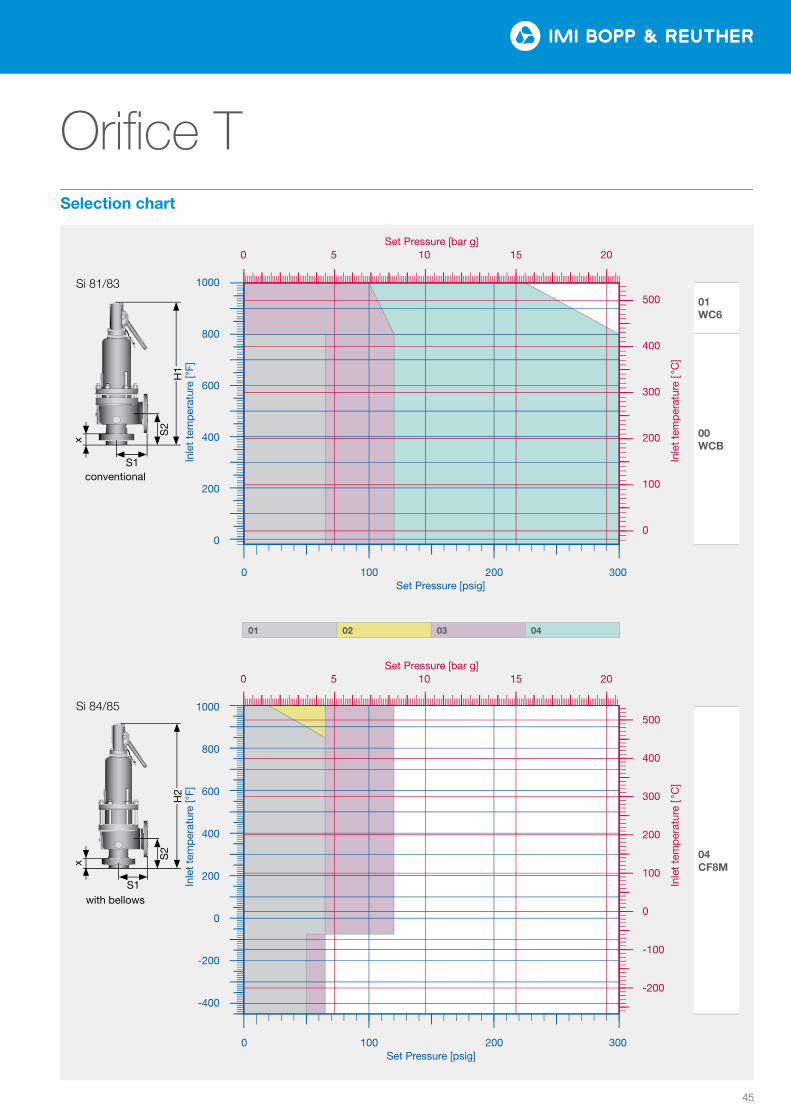
45
Orifice T
01/02 03 04
Tem
pera
tur [
°F]
Druck [psi]
0
200
400
600
800
1000
0 100 200 300
0
100
200
300
400
500
0 5 10 15 20
Tem
pera
tur [
°C]
Druck [bar]
Tem
pera
tur [
°F]
Druck [psi]
−400
−200
0
200
400
600
800
1000
0 100 200 300
−200
−100
0
100
200
300
400
500
0 5 10 15 20Te
mpe
ratu
r [°C
]Druck [bar]
01 02 03 04
Tem
pera
tur [
°F]
Druck [psi]
0
200
400
600
800
1000
0 100 200 300
0
100
200
300
400
500
0 5 10 15 20
Tem
pera
tur [
°C]
Druck [bar]
Tem
pera
tur [
°F]
Druck [psi]
−400
−200
0
200
400
600
800
1000
0 100 200 300
−200
−100
0
100
200
300
400
500
0 5 10 15 20Te
mpe
ratu
r [°C
]
Druck [bar]
01 WC6
00 WCB
04 CF8M
Inle
t te
mp
erat
ure
[ °C
] In
let
tem
per
atur
e [ °
C]
Inle
t te
mp
erat
ure
[°F]
In
let
tem
per
atur
e [°
F]
Si 81/83
S1conventional
S2
x
H1
1000
800
600
400
200
0
1000
800
600
400
200
0
-200
-400
500
400
300
200
100
0
500
400
300
200
100
0
-100
-200
Set Pressure [bar g] 0 5 10 15 20
0 100 200 300Set Pressure [psig]
0 100 200 300 Set Pressure [psig]
Set Pressure [bar g] 0 5 10 15 20
01 02 03 04
with bellows
Si 84/85
S1
S2
H2
x
Selection chart
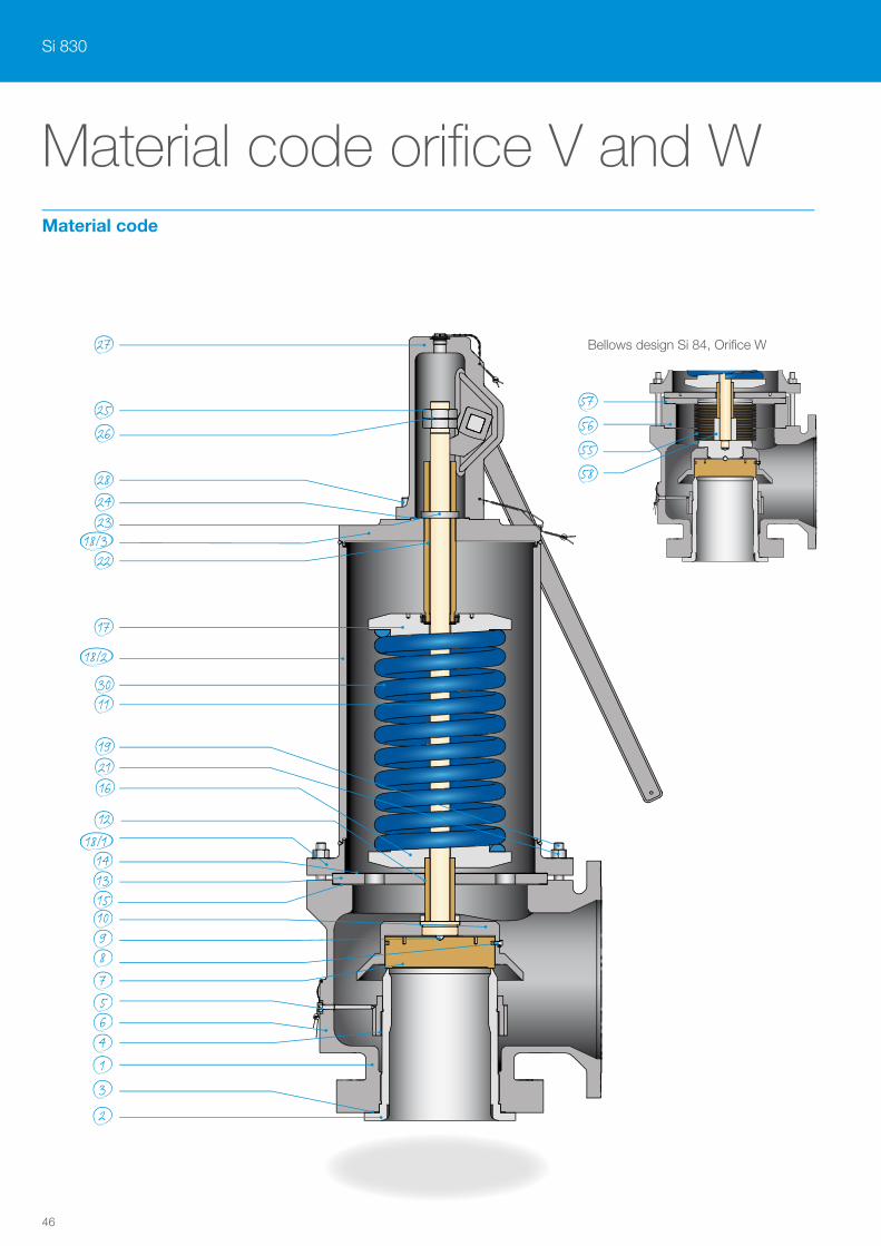
Si 830
46
2428
25
27
22
26
23
2119
11
12
10
89
756
1
2
3
4
15
30
18/1
18/2
18/3
13
16
17
14
Material code orifice V and WMaterial code
5655
57
58
Bellows design Si 84, Orifice W
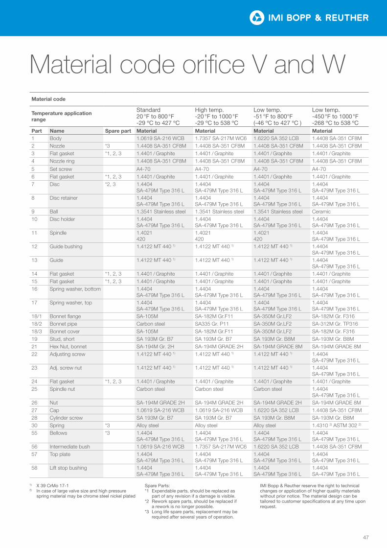
47
Material code
Temperature application range
Standard 20 °F to 800 °F -29 ºC to 427 ºC
High temp. -20 °F to 1000 °F -29 ºC to 538 ºC
Low temp. -51 °F to 800°F (-46 ºC to 427 ºC )
Low temp. -450 °F to 1000 °F -268 ºC to 538 ºC
Part Name Spare part Material Material Material Material1 Body 1.0619 SA-216 WCB 1.7357 SA-217M WC6 1.6220 SA 352 LCB 1.4408 SA-351 CF8M2 Nozzle *3 1.4408 SA-351 CF8M 1.4408 SA-351 CF8M 1.4408 SA-351 CF8M 1.4408 SA-351 CF8M3 Flat gasket *1, 2, 3 1.4401 / Graphite 1.4401 / Graphite 1.4401 / Graphite 1.4401 / Graphite4 Nozzle ring 1.4408 SA-351 CF8M 1.4408 SA-351 CF8M 1.4408 SA-351 CF8M 1.4408 SA-351 CF8M
5 Set screw A4-70 A4-70 A4-70 A4-706 Flat gasket *1, 2, 3 1.4401 / Graphite 1.4401 / Graphite 1.4401 / Graphite 1.4401 / Graphite7 Disc *2, 3 1.4404
SA-479M Type 316 L1.4404 SA-479M Type 316 L
1.4404 SA-479M Type 316 L
1.4404 SA-479M Type 316 L
8 Disc retainer 1.4404 SA-479M Type 316 L
1.4404 SA-479M Type 316 L
1.4404 SA-479M Type 316 L
1.4404 SA-479M Type 316 L
9 Ball 1.3541 Stainless steel 1.3541 Stainless steel 1.3541 Stainless steel Ceramic10 Disc holder 1.4404
SA-479M Type 316 L1.4404 SA-479M Type 316 L
1.4404 SA-479M Type 316 L
1.4404 SA-479M Type 316 L
11 Spindle 1.4021 420
1.4021 420
1.4021 420
1.4404 SA-479M Type 316 L
12 Guide bushing 1.4122 MT 440 1) 1.4122 MT 440 1) 1.4122 MT 440 1) 1.4404 SA-479M Type 316 L
13 Guide 1.4122 MT 440 1) 1.4122 MT 440 1) 1.4122 MT 440 1) 1.4404 SA-479M Type 316 L
14 Flat gasket *1, 2, 3 1.4401 / Graphite 1.4401 / Graphite 1.4401 / Graphite 1.4401 / Graphite15 Flat gasket *1, 2, 3 1.4401 / Graphite 1.4401 / Graphite 1.4401 / Graphite 1.4401 / Graphite16 Spring washer, bottom 1.4404
SA-479M Type 316 L1.4404 SA-479M Type 316 L
1.4404 SA-479M Type 316 L
1.4404 SA-479M Type 316 L
17 Spring washer, top 1.4404 SA-479M Type 316 L
1.4404 SA-479M Type 316 L
1.4404 SA-479M Type 316 L
1.4404 SA-479M Type 316 L
18/1 Bonnet flange SA-105M SA-182M Gr.F11 SA-350M Gr.LF2 SA-182M Gr. F31618/2 Bonnet pipe Carbon steel SA335 Gr. P11 SA-350M Gr.LF2 SA-312M Gr. TP31618/3 Bonnet cover SA-105M SA-182M Gr.F11 SA-350M Gr.LF2 SA-182M Gr. F31619 Stud, short SA 193M Gr. B7 SA 193M Gr. B7 SA 193M Gr. B8M SA-193M Gr. B8M21 Hex Nut, bonnet SA-194M Gr. 2H SA-194M GRADE 2H SA-194M GRADE 8M SA-194M GRADE 8M22 Adjusting screw 1.4122 MT 440 1) 1.4122 MT 440 1) 1.4122 MT 440 1) 1.4404
SA-479M Type 316 L23 Adj. screw nut 1.4122 MT 440 1) 1.4122 MT 440 1) 1.4122 MT 440 1) 1.4404
SA-479M Type 316 L24 Flat gasket *1, 2, 3 1.4401 / Graphite 1.4401 / Graphite 1.4401 / Graphite 1.4401 / Graphite25 Spindle nut Carbon steel Carbon steel Carbon steel 1.4404
SA-479M Type 316 L26 Nut SA-194M GRADE 2H SA-194M GRADE 2H SA-194M GRADE 2H SA-194M GRADE 8M27 Cap 1.0619 SA-216 WCB 1.0619 SA-216 WCB 1.6220 SA 352 LCB 1.4408 SA-351 CF8M28 Cylinder screw SA 193M Gr. B7 SA 193M Gr. B7 SA 193M Gr. B8M SA-193M Gr. B8M30 Spring *3 Alloy steel Alloy steel Alloy steel 1.4310 2) ASTM 302 2)
55 Bellows *3 1.4404 SA-479M Type 316 L
1.4404 SA-479M Type 316 L
1.4404 SA-479M Type 316 L
1.4404 SA-479M Type 316 L
56 Intermediate bush 1.0619 SA-216 WCB 1.7357 SA-217M WC6 1.6220 SA 352 LCB 1.4408 SA-351 CF8M57 Top plate 1.4404
SA-479M Type 316 L1.4404 SA-479M Type 316 L
1.4404 SA-479M Type 316 L
1.4404 SA-479M Type 316 L
58 Lift stop bushing 1.4404 SA-479M Type 316 L
1.4404 SA-479M Type 316 L
1.4404 SA-479M Type 316 L
1.4404 SA-479M Type 316 L
1) X 39 CrMo 17-12) In case of large valve size and high pressure
spring material may be chrome steel nickel plated
Spare Parts:*1 Expendable parts, should be replaced as
part of any revision if a damage is visible.*2 Rework spare parts, should be replaced if
a rework is no longer possible.*3 Long life spare parts, replacement may be
required after several years of operation.
IMI Bopp & Reuther reserve the right to technical changes or application of higher quality materials without prior notice. The material design can be tailored to customer specifications at any time upon request.
Material code orifice V and W
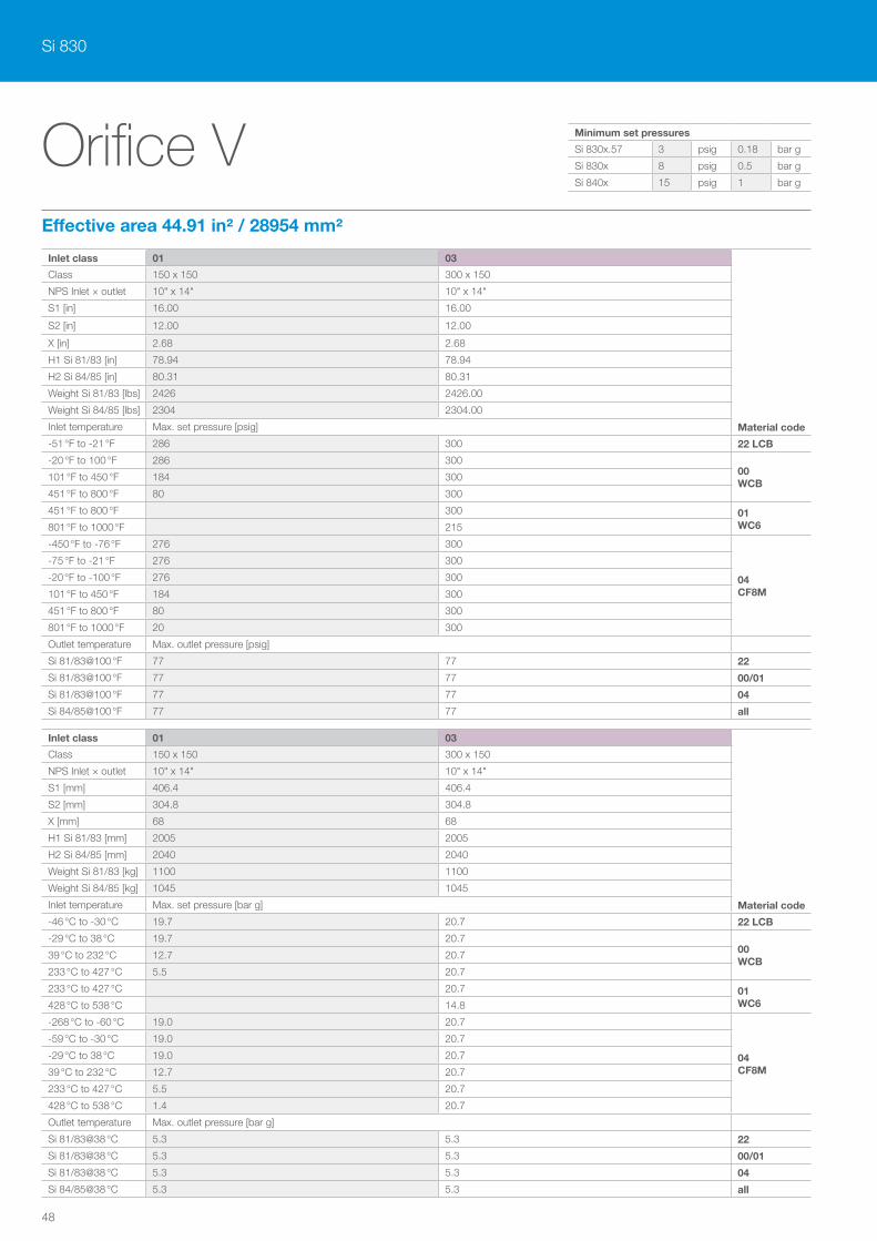
Si 830
48
Orifice VEffective area 44.91 in² / 28954 mm²
Inlet class 01 03
Material code
Class 150 x 150 300 x 150
NPS Inlet × outlet 10" x 14" 10" x 14"
S1 [in] 16.00 16.00
S2 [in] 12.00 12.00
X [in] 2.68 2.68
H1 Si 81/83 [in] 78.94 78.94
H2 Si 84/85 [in] 80.31 80.31
Weight Si 81/83 [lbs] 2426 2426.00
Weight Si 84/85 [lbs] 2304 2304.00
Inlet temperature Max. set pressure [psig]
-51 °F to -21 °F 286 300 22 LCB
-20 °F to 100 °F 286 30000 WCB
101 °F to 450 °F 184 300
451 °F to 800 °F 80 300
451 °F to 800 °F 300 01 WC6801 °F to 1000 °F 215
-450 °F to -76 °F 276 300
04 CF8M
-75 °F to -21 °F 276 300
-20 °F to -100 °F 276 300
101 °F to 450 °F 184 300
451 °F to 800 °F 80 300
801 °F to 1000 °F 20 300
Outlet temperature Max. outlet pressure [psig]
Si 81/83@100 °F 77 77 22
Si 81/83@100 °F 77 77 00/01
Si 81/83@100 °F 77 77 04
Si 84/85@100 °F 77 77 all
Inlet class 01 03
Material code
Class 150 x 150 300 x 150
NPS Inlet × outlet 10" x 14" 10" x 14"
S1 [mm] 406.4 406.4
S2 [mm] 304.8 304.8
X [mm] 68 68
H1 Si 81/83 [mm] 2005 2005
H2 Si 84/85 [mm] 2040 2040
Weight Si 81/83 [kg] 1100 1100
Weight Si 84/85 [kg] 1045 1045
Inlet temperature Max. set pressure [bar g]
-46 °C to -30 °C 19.7 20.7 22 LCB
-29 °C to 38 °C 19.7 20.700 WCB
39 °C to 232 °C 12.7 20.7
233 °C to 427 °C 5.5 20.7
233 °C to 427 °C 20.7 01 WC6428 °C to 538 °C 14.8
-268 °C to -60 °C 19.0 20.7
04 CF8M
-59 °C to -30 °C 19.0 20.7
-29 °C to 38 °C 19.0 20.7
39 °C to 232 °C 12.7 20.7
233 °C to 427 °C 5.5 20.7
428 °C to 538 °C 1.4 20.7
Outlet temperature Max. outlet pressure [bar g]
Si 81/83@38 °C 5.3 5.3 22
Si 81/83@38 °C 5.3 5.3 00/01
Si 81/83@38 °C 5.3 5.3 04
Si 84/85@38 °C 5.3 5.3 all
Minimum set pressures
Si 830x.57 3 psig 0.18 bar g
Si 830x 8 psig 0.5 bar g
Si 840x 15 psig 1 bar g
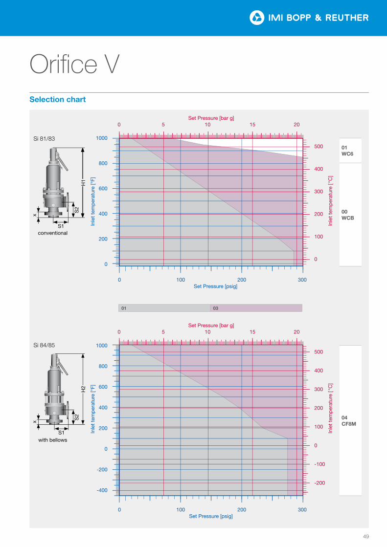
49
Orifice V
01 03
Tem
pera
tur [
°F]
Druck [psi]
0
200
400
600
800
1000
0 100 200 300
0
100
200
300
400
500
0 5 10 15 20
Tem
pera
tur [
°C]
Druck [bar]
Tem
pera
tur [
°F]
Druck [psi]
−400
−200
0
200
400
600
800
1000
0 100 200 300
−200
−100
0
100
200
300
400
500
0 5 10 15 20Te
mpe
ratu
r [°C
]Druck [bar]
01 03
Tem
pera
tur [
°F]
Druck [psi]
0
200
400
600
800
1000
0 100 200 300
0
100
200
300
400
500
0 5 10 15 20
Tem
pera
tur [
°C]
Druck [bar]
Tem
pera
tur [
°F]
Druck [psi]
−400
−200
0
200
400
600
800
1000
0 100 200 300
−200
−100
0
100
200
300
400
500
0 5 10 15 20Te
mpe
ratu
r [°C
]
Druck [bar]
01 WC6
00 WCB
04 CF8M
Inle
t te
mp
erat
ure
[ °C
] In
let
tem
per
atur
e [ °
C]
Inle
t te
mp
erat
ure
[°F]
In
let
tem
per
atur
e [°
F]
Si 81/83
S1conventional
S2
x
H1
1000
800
600
400
200
0
1000
800
600
400
200
0
-200
-400
500
400
300
200
100
0
500
400
300
200
100
0
-100
-200
Set Pressure [bar g] 0 5 10 15 20
0 100 200 300Set Pressure [psig]
0 100 200 300 Set Pressure [psig]
Set Pressure [bar g] 0 5 10 15 20
01 03
with bellows
Si 84/85
S1
S2
H2
x
Selection chart
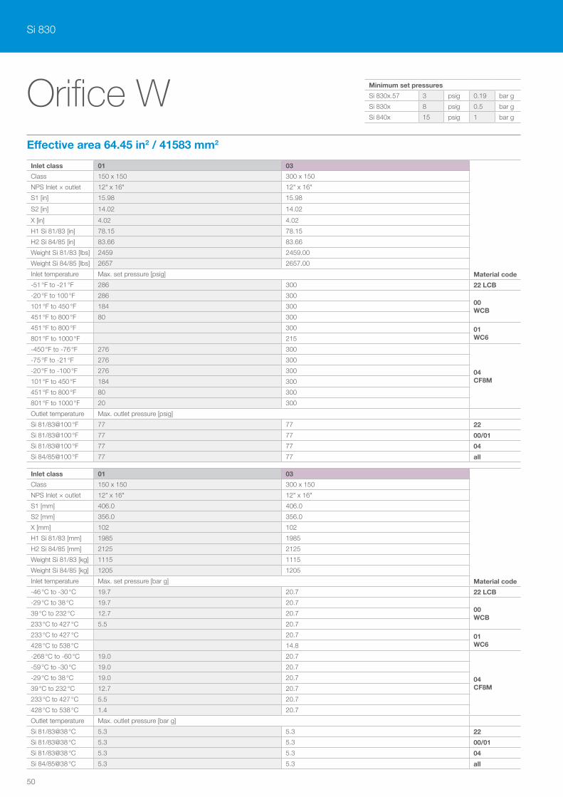
Si 830
50
Orifice WEffective area 64.45 in2 / 41583 mm2
Inlet class 01 03
Material code
Class 150 x 150 300 x 150
NPS Inlet × outlet 12" x 16" 12" x 16"
S1 [in] 15.98 15.98
S2 [in] 14.02 14.02
X [in] 4.02 4.02
H1 Si 81/83 [in] 78.15 78.15
H2 Si 84/85 [in] 83.66 83.66
Weight Si 81/83 [lbs] 2459 2459.00
Weight Si 84/85 [lbs] 2657 2657.00
Inlet temperature Max. set pressure [psig]
-51 °F to -21 °F 286 300 22 LCB
-20 °F to 100 °F 286 30000 WCB
101 °F to 450 °F 184 300
451 °F to 800 °F 80 300
451 °F to 800 °F 300 01 WC6801 °F to 1000 °F 215
-450 °F to -76 °F 276 300
04 CF8M
-75 °F to -21 °F 276 300
-20 °F to -100 °F 276 300
101 °F to 450 °F 184 300
451 °F to 800 °F 80 300
801 °F to 1000 °F 20 300
Outlet temperature Max. outlet pressure [psig]
Si 81/83@100 °F 77 77 22
Si 81/83@100 °F 77 77 00/01
Si 81/83@100 °F 77 77 04
Si 84/85@100 °F 77 77 all
Inlet class 01 03
Material code
Class 150 x 150 300 x 150
NPS Inlet × outlet 12" x 16" 12" x 16"
S1 [mm] 406.0 406.0
S2 [mm] 356.0 356.0
X [mm] 102 102
H1 Si 81/83 [mm] 1985 1985
H2 Si 84/85 [mm] 2125 2125
Weight Si 81/83 [kg] 1115 1115
Weight Si 84/85 [kg] 1205 1205
Inlet temperature Max. set pressure [bar g]
-46 °C to -30 °C 19.7 20.7 22 LCB
-29 °C to 38 °C 19.7 20.700 WCB
39 °C to 232 °C 12.7 20.7
233 °C to 427 °C 5.5 20.7
233 °C to 427 °C 20.7 01 WC6428 °C to 538 °C 14.8
-268 °C to -60 °C 19.0 20.7
04 CF8M
-59 °C to -30 °C 19.0 20.7
-29 °C to 38 °C 19.0 20.7
39 °C to 232 °C 12.7 20.7
233 °C to 427 °C 5.5 20.7
428 °C to 538 °C 1.4 20.7
Outlet temperature Max. outlet pressure [bar g]
Si 81/83@38 °C 5.3 5.3 22
Si 81/83@38 °C 5.3 5.3 00/01
Si 81/83@38 °C 5.3 5.3 04
Si 84/85@38 °C 5.3 5.3 all
Minimum set pressures
Si 830x.57 3 psig 0.19 bar g
Si 830x 8 psig 0.5 bar g
Si 840x 15 psig 1 bar g
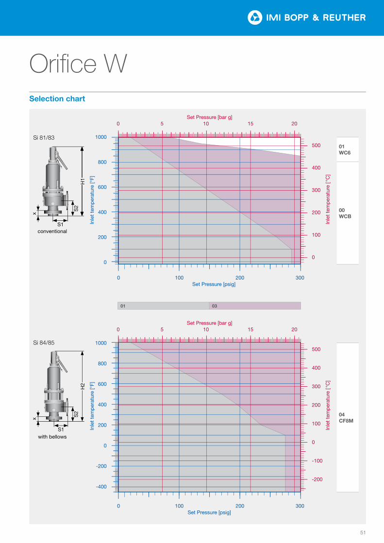
51
Orifice W
01 03
Tem
pera
tur [
°F]
Druck [psi]
0
200
400
600
800
1000
100 200 300
0
100
200
300
400
500
0 5 10 15 20
Tem
pera
tur [
°C]
Druck [bar]
Tem
pera
tur [
°F]
Druck [psi]
−400
−200
0
200
400
600
800
1000
0 100 200 300
−200
−100
0
100
200
300
400
500
0 5 10 15 20Te
mpe
ratu
r [°C
]Druck [bar]
01 03
Tem
pera
tur [
°F]
Druck [psi]
0
200
400
600
800
1000
100 200 300
0
100
200
300
400
500
0 5 10 15 20
Tem
pera
tur [
°C]
Druck [bar]
Tem
pera
tur [
°F]
Druck [psi]
−400
−200
0
200
400
600
800
1000
0 100 200 300
−200
−100
0
100
200
300
400
500
0 5 10 15 20Te
mpe
ratu
r [°C
]
Druck [bar]
01 WC6
00 WCB
04 CF8M
Inle
t te
mp
erat
ure
[ °C
] In
let
tem
per
atur
e [ °
C]
Inle
t te
mp
erat
ure
[°F]
In
let
tem
per
atur
e [°
F]
Si 81/83
S1conventional
S2
x
H1
1000
800
600
400
200
0
1000
800
600
400
200
0
-200
-400
500
400
300
200
100
0
500
400
300
200
100
0
-100
-200
Set Pressure [bar g] 0 5 10 15 20
0 100 200 300Set Pressure [psig]
0 100 200 300 Set Pressure [psig]
Set Pressure [bar g] 0 5 10 15 20
01 03
with bellows
Si 84/85
S1
S2
H2
x
Selection chart
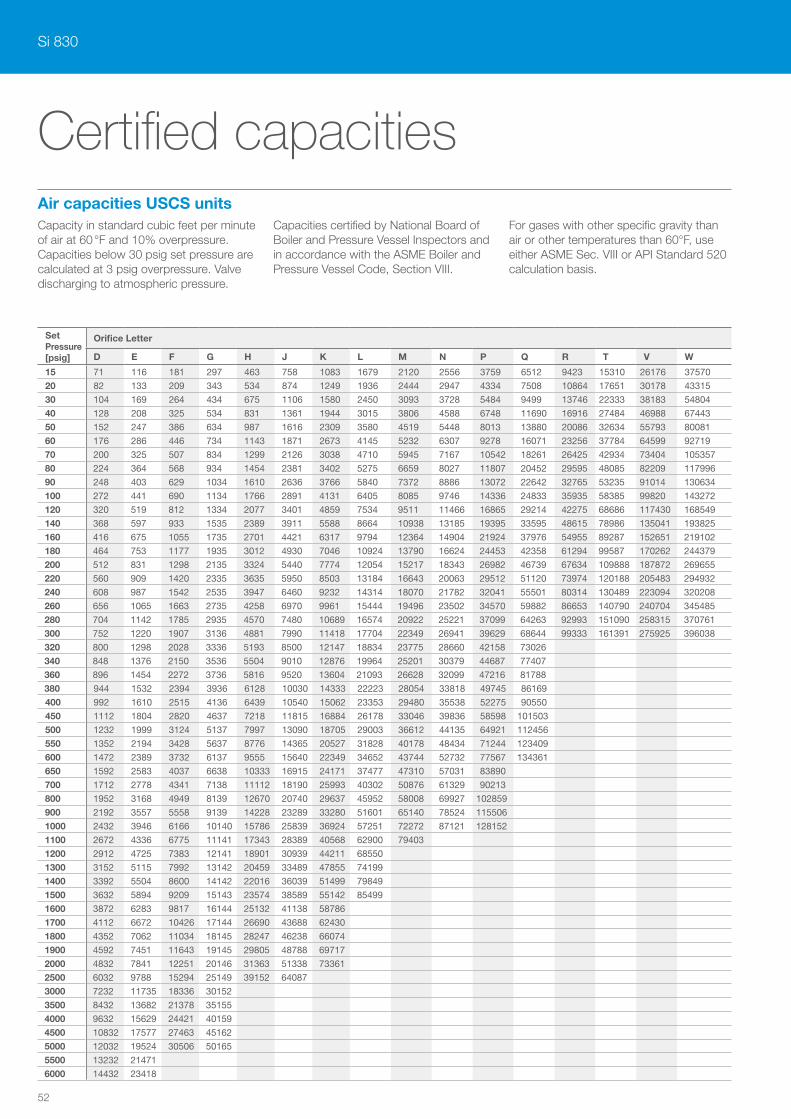
Si 830
52
Set Pressure[psig]
Orifice Letter
D E F G H J K L M N P Q R T V W
15 71 116 181 297 463 758 1083 1679 2120 2556 3759 6512 9423 15310 26176 37570
20 82 133 209 343 534 874 1249 1936 2444 2947 4334 7508 10864 17651 30178 43315
30 104 169 264 434 675 1106 1580 2450 3093 3728 5484 9499 13746 22333 38183 54804
40 128 208 325 534 831 1361 1944 3015 3806 4588 6748 11690 16916 27484 46988 67443
50 152 247 386 634 987 1616 2309 3580 4519 5448 8013 13880 20086 32634 55793 80081
60 176 286 446 734 1143 1871 2673 4145 5232 6307 9278 16071 23256 37784 64599 92719
70 200 325 507 834 1299 2126 3038 4710 5945 7167 10542 18261 26425 42934 73404 105357
80 224 364 568 934 1454 2381 3402 5275 6659 8027 11807 20452 29595 48085 82209 117996
90 248 403 629 1034 1610 2636 3766 5840 7372 8886 13072 22642 32765 53235 91014 130634
100 272 441 690 1134 1766 2891 4131 6405 8085 9746 14336 24833 35935 58385 99820 143272
120 320 519 812 1334 2077 3401 4859 7534 9511 11466 16865 29214 42275 68686 117430 168549
140 368 597 933 1535 2389 3911 5588 8664 10938 13185 19395 33595 48615 78986 135041 193825
160 416 675 1055 1735 2701 4421 6317 9794 12364 14904 21924 37976 54955 89287 152651 219102
180 464 753 1177 1935 3012 4930 7046 10924 13790 16624 24453 42358 61294 99587 170262 244379
200 512 831 1298 2135 3324 5440 7774 12054 15217 18343 26982 46739 67634 109888 187872 269655
220 560 909 1420 2335 3635 5950 8503 13184 16643 20063 29512 51120 73974 120188 205483 294932
240 608 987 1542 2535 3947 6460 9232 14314 18070 21782 32041 55501 80314 130489 223094 320208
260 656 1065 1663 2735 4258 6970 9961 15444 19496 23502 34570 59882 86653 140790 240704 345485
280 704 1142 1785 2935 4570 7480 10689 16574 20922 25221 37099 64263 92993 151090 258315 370761
300 752 1220 1907 3136 4881 7990 11418 17704 22349 26941 39629 68644 99333 161391 275925 396038
320 800 1298 2028 3336 5193 8500 12147 18834 23775 28660 42158 73026
340 848 1376 2150 3536 5504 9010 12876 19964 25201 30379 44687 77407
360 896 1454 2272 3736 5816 9520 13604 21093 26628 32099 47216 81788
380 944 1532 2394 3936 6128 10030 14333 22223 28054 33818 49745 86169
400 992 1610 2515 4136 6439 10540 15062 23353 29480 35538 52275 90550
450 1112 1804 2820 4637 7218 11815 16884 26178 33046 39836 58598 101503
500 1232 1999 3124 5137 7997 13090 18705 29003 36612 44135 64921 112456
550 1352 2194 3428 5637 8776 14365 20527 31828 40178 48434 71244 123409
600 1472 2389 3732 6137 9555 15640 22349 34652 43744 52732 77567 134361
650 1592 2583 4037 6638 10333 16915 24171 37477 47310 57031 83890
700 1712 2778 4341 7138 11112 18190 25993 40302 50876 61329 90213
800 1952 3168 4949 8139 12670 20740 29637 45952 58008 69927 102859
900 2192 3557 5558 9139 14228 23289 33280 51601 65140 78524 115506
1000 2432 3946 6166 10140 15786 25839 36924 57251 72272 87121 128152
1100 2672 4336 6775 11141 17343 28389 40568 62900 79403
1200 2912 4725 7383 12141 18901 30939 44211 68550
1300 3152 5115 7992 13142 20459 33489 47855 74199
1400 3392 5504 8600 14142 22016 36039 51499 79849
1500 3632 5894 9209 15143 23574 38589 55142 85499
1600 3872 6283 9817 16144 25132 41138 58786
1700 4112 6672 10426 17144 26690 43688 62430
1800 4352 7062 11034 18145 28247 46238 66074
1900 4592 7451 11643 19145 29805 48788 69717
2000 4832 7841 12251 20146 31363 51338 73361
2500 6032 9788 15294 25149 39152 64087
3000 7232 11735 18336 30152
3500 8432 13682 21378 35155
4000 9632 15629 24421 40159
4500 10832 17577 27463 45162
5000 12032 19524 30506 50165
5500 13232 21471
6000 14432 23418
Air capacities USCS units
Certified capacities
Capacity in standard cubic feet per minute of air at 60 °F and 10% overpressure. Capaci ties below 30 psig set pressure are calculated at 3 psig overpressure. Valve discharging to atmospheric pressure.
Capacities certified by National Board of Boiler and Pressure Vessel Inspectors and in accordance with the ASME Boiler and Pressure Vessel Code, Section VIII.
For gases with other specific gravity than air or other temperatures than 60°F, use either ASME Sec. VIII or API Standard 520 calculation basis.
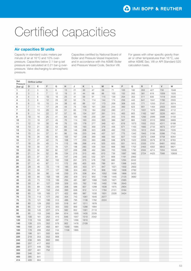
53
Set Pressure[bar g]
Orifice Letter
D E F G H J K L M N P Q R T V W
1 2 3 5 8 13 21 30 47 59 71 105 182 263 427 730 1048
2 3 5 7 12 19 31 44 68 86 103 152 263 381 619 1059 1520
3 4 6 10 16 25 41 59 91 115 139 204 353 511 830 1418 2035
4 5 8 12 20 32 52 74 114 144 174 256 443 641 1041 1780 2555
5 6 10 15 24 38 62 89 137 173 209 308 533 771 1253 2141 3074
6 7 11 17 28 44 73 104 161 203 244 360 623 901 1464 2503 3593
7 8 13 20 33 51 83 119 184 232 280 411 713 1031 1676 2865 4112
8 9 14 22 37 57 93 134 207 261 315 463 803 1162 1887 3226 4631
9 10 16 25 41 64 104 149 230 291 350 515 893 1292 2099 3588 5150
10 11 18 27 45 70 114 163 253 320 386 567 983 1422 2310 3950 5669
11 12 19 30 49 76 125 178 277 349 421 619 1073 1552 2522 4311 6188
12 13 21 32 53 83 135 193 300 379 456 671 1163 1682 2733 4673 6707
13 14 22 35 57 89 146 208 323 408 492 723 1253 1812 2945 5034 7226
14 15 24 37 61 96 156 223 346 437 527 775 1342 1943 3156 5396 7745
15 16 26 40 65 102 167 238 369 466 562 827 1432 2073 3368 5758 8264
16 17 27 42 70 108 177 253 393 496 598 879 1522 2203 3579 6119 8783
17 18 29 45 74 115 188 268 416 525 633 931 1612 2333 3791 6481 9302
18 19 30 47 78 121 198 283 439 554 668 983 1702 2463 4002 6843 9821
19 20 32 50 82 127 209 298 462 584 703 1035 1792 2594 4214 7204 10340
20 21 34 52 86 134 219 313 485 613 739 1087 1882 2724 4425 7566 10859
22 23 37 57 94 147 240 343 532 671 809 1191 2062
24 25 40 62 102 159 261 373 578 730 880 1294 2242
26 27 43 67 111 172 282 403 625 789 951 1398 2422
28 29 46 72 119 185 303 433 671 847 1021 1502 2602
30 31 50 77 127 198 324 463 718 906 1092 1606 2782
35 35 58 90 148 230 376 538 834 1052 1268 1866 3232
40 40 66 102 168 262 429 612 950 1199 1445 2125 3682
45 45 73 115 189 294 481 687 1066 1345 1621 2385
50 50 81 127 209 326 533 762 1182 1492 1798 2645
55 55 89 140 230 358 586 837 1298 1638 1975 2904
60 60 97 152 250 390 638 912 1414 1784 2151 3164
65 65 105 165 271 422 690 987 1530 1931 2328 3424
70 70 113 177 292 454 743 1061 1646 2077
75 75 121 190 312 486 795 1136 1762 2224
80 80 129 202 333 518 847 1211 1878
85 85 137 215 353 550 900 1286 1994
90 90 145 227 374 582 952 1361 2110
95 95 153 240 394 614 1005 1435 2226
100 100 161 252 415 646 1057 1510 2342
120 119 193 302 497 774 1266 1810
140 139 225 352 579 902 1476 2109
160 159 257 402 661 1030 1685
180 178 289 452 744 1158 1895
200 198 321 502 826
220 218 353 552 908
240 238 385 602 990
260 257 417 652
280 277 449 702
300 297 481 752
350 346 561
400 395 641
414 409 664
Air capacities SI units
Certified capacities
Capacity in standard cubic meters per minute of air at 16 °C and 10% over-pressure. Capacities below 2.1 bar-g set pressure are calculated at 0.21 bar-g over-pressure. Valve discharging to atmospheric pressure.
Capacities certified by National Board of Boiler and Pressure Vessel Inspectors and in accordance with the ASME Boiler and Pressure Vessel Code, Section VIII.
For gases with other specific gravity than air or other tem peratures than 16 °C, use either ASME Sec. VIII or API Standard 520 calculation basis.
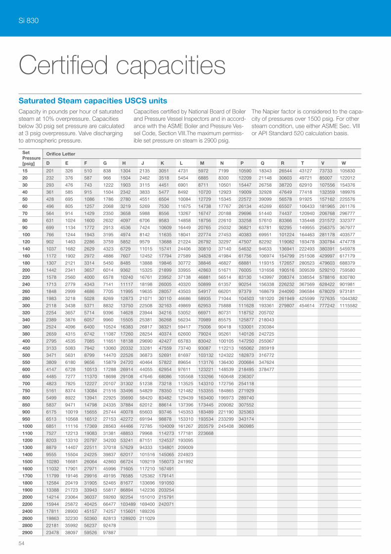
Si 830
54
Set Pressure[psig]
Orifice Letter
D E F G H J K L M N P Q R T V W
15 201 326 510 838 1304 2135 3051 4731 5972 7199 10590 18343 26544 43127 73733 105830
20 232 376 587 966 1504 2462 3518 5454 6885 8300 12209 21148 30603 49721 85007 122012
30 293 476 743 1222 1903 3115 4451 6901 8711 10501 15447 26758 38720 62910 107556 154376
40 361 585 915 1504 2342 3833 5477 8492 10720 12923 19009 32928 47649 77418 132359 189976
50 428 695 1086 1786 2780 4551 6504 10084 12729 15345 22572 39099 56578 91925 157162 225576
60 496 805 1257 2068 3219 5269 7530 11675 14738 17767 26134 45269 65507 106433 181965 261176
70 564 914 1429 2350 3658 5988 8556 13267 16747 20188 29696 51440 74437 120940 206768 296777
80 631 1024 1600 2632 4097 6706 9583 14858 18756 22610 33258 57610 83366 135448 231572 332377
90 699 1134 1772 2913 4536 7424 10609 16449 20765 25032 36821 63781 92295 149955 256375 367977
100 766 1244 1943 3195 4974 8142 11635 18041 22774 27453 40383 69951 101224 164463 281178 403577
120 902 1463 2286 3759 5852 9579 13688 21224 26792 32297 47507 82292 119082 193478 330784 474778
140 1037 1682 2629 4323 6729 11015 15741 24406 30810 37140 54632 94633 136941 222493 380391 545978
160 1172 1902 2972 4886 7607 12452 17794 27589 34828 41984 61756 106974 154799 251508 429997 617179
180 1307 2121 3314 5450 8485 13888 19846 30772 38846 46827 68881 119315 172657 280523 479603 688379
200 1442 2341 3657 6014 9362 15325 21899 33955 42863 51671 76005 131656 190516 309539 529210 759580
220 1578 2560 4000 6578 10240 16761 23952 37138 46881 56514 83130 143997 208374 338554 578816 830780
240 1713 2779 4343 7141 11117 18198 26005 40320 50899 61357 90254 156338 226232 367569 628422 901981
260 1848 2999 4686 7705 11995 19635 28057 43503 54917 66201 97379 168679 244090 396584 678029 973181
280 1983 3218 5028 8269 12873 21071 30110 46686 58935 71044 104503 181020 261949 425599 727635 1044382
300 2118 3438 5371 8832 13750 22508 32163 49869 62953 75888 111628 193361 279807 454614 777242 1115582
320 2254 3657 5714 9396 14628 23944 34216 53052 66971 80731 118752 205702
340 2389 3876 6057 9960 15505 25381 36268 56234 70989 85575 125877 218043
360 2524 4096 6400 10524 16383 26817 38321 59417 75006 90418 133001 230384
380 2659 4315 6742 11087 17260 28254 40374 62600 79024 95261 140126 242725
400 2795 4535 7085 11651 18138 29690 42427 65783 83042 100105 147250 255067
450 3133 5083 7942 13060 20332 33281 47559 73740 93087 112213 165062 285919
500 3471 5631 8799 14470 22526 36873 52691 81697 103132 124322 182873 316772
550 3809 6180 9656 15879 24720 40464 57822 89654 113176 136430 200684 347624
600 4147 6728 10513 17288 26914 44055 62954 97611 123221 148539 218495 378477
650 4485 7277 11370 18698 29108 47646 68086 105568 133266 160648 236307
700 4823 7825 12227 20107 31302 51238 73218 113525 143310 172756 254118
750 5161 8374 13084 21516 33496 54829 78350 121482 153355 184865 271929
800 5499 8922 13941 22925 35690 58420 83482 129439 163400 196973 289740
850 5837 9471 14798 24335 37884 62012 88614 137396 173445 209082 307552
900 6175 10019 15655 25744 40078 65603 93746 145353 183489 221190 325363
950 6513 10568 16512 27153 42272 69194 98878 153310 193534 233299 343174
1000 6851 11116 17369 28563 44466 72785 104009 161267 203579 245408 360985
1100 7527 12213 19083 31381 48853 79968 114273 177181 223668
1200 8203 13310 20797 34200 53241 87151 124537 193095
1300 8879 14407 22511 37018 57629 94333 134801 209009
1400 9555 15504 24225 39837 62017 101516 145065 224923
1500 10280 16681 26064 42860 66724 109219 156073 241992
1600 11032 17901 27971 45996 71605 117210 167491
1700 11799 19146 29916 49195 76585 125362 179141
1800 12584 20419 31905 52465 81677 133696 191050
1900 13388 21723 33943 55817 86894 142236 203254
2000 14214 23064 36037 59260 92254 151010 215791
2200 15944 25872 40425 66477 103489 169400 242071
2400 17811 28900 45157 74257 115601 189226
2600 19863 32230 50360 82813 128920 211029
2800 22181 35992 56237 92478
2900 23478 38097 59526 97887
Saturated Steam capacities USCS units
Certified capacities
Capacity in pounds per hour of saturated steam at 10% overpressure. Capacities below 30 psig set pressure are calculated at 3 psig overpressure. Valve discharging to atmospheric pressure.
Capacities certified by National Board of Boiler and Pressure Vessel Inspectors and in accord-ance with the ASME Boiler and Pressure Ves-sel Code, Section VIII.The maximum permiss-ible set pressure on steam is 2900 psig.
The Napier factor is considered to the capa-city of pressures over 1500 psig. For other steam condition, use either ASME Sec. VIII or API Standard 520 calculation basis.
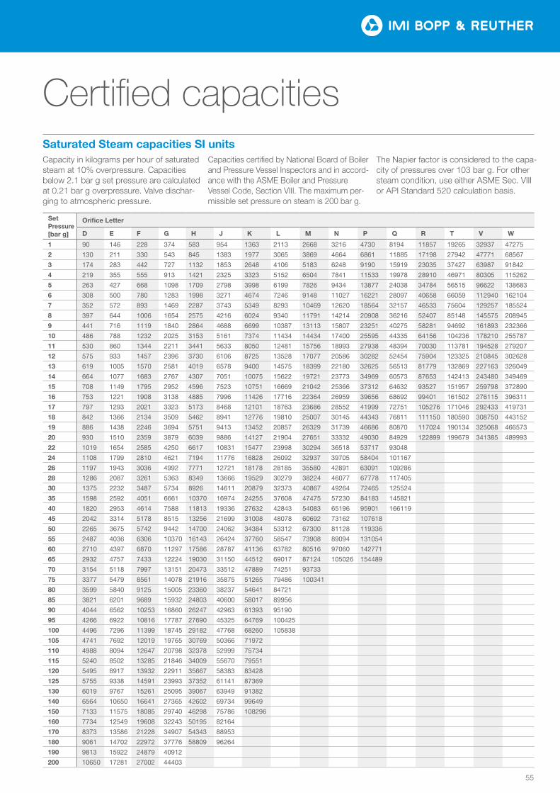
55
Set Pressure[bar g]
Orifice Letter
D E F G H J K L M N P Q R T V W
1 90 146 228 374 583 954 1363 2113 2668 3216 4730 8194 11857 19265 32937 47275
2 130 211 330 543 845 1383 1977 3065 3869 4664 6861 11885 17198 27942 47771 68567
3 174 283 442 727 1132 1853 2648 4106 5183 6248 9190 15919 23035 37427 63987 91842
4 219 355 555 913 1421 2325 3323 5152 6504 7841 11533 19978 28910 46971 80305 115262
5 263 427 668 1098 1709 2798 3998 6199 7826 9434 13877 24038 34784 56515 96622 138683
6 308 500 780 1283 1998 3271 4674 7246 9148 11027 16221 28097 40658 66059 112940 162104
7 352 572 893 1469 2287 3743 5349 8293 10469 12620 18564 32157 46533 75604 129257 185524
8 397 644 1006 1654 2575 4216 6024 9340 11791 14214 20908 36216 52407 85148 145575 208945
9 441 716 1119 1840 2864 4688 6699 10387 13113 15807 23251 40275 58281 94692 161893 232366
10 486 788 1232 2025 3153 5161 7374 11434 14434 17400 25595 44335 64156 104236 178210 255787
11 530 860 1344 2211 3441 5633 8050 12481 15756 18993 27938 48394 70030 113781 194528 279207
12 575 933 1457 2396 3730 6106 8725 13528 17077 20586 30282 52454 75904 123325 210845 302628
13 619 1005 1570 2581 4019 6578 9400 14575 18399 22180 32625 56513 81779 132869 227163 326049
14 664 1077 1683 2767 4307 7051 10075 15622 19721 23773 34969 60573 87653 142413 243480 349469
15 708 1149 1795 2952 4596 7523 10751 16669 21042 25366 37312 64632 93527 151957 259798 372890
16 753 1221 1908 3138 4885 7996 11426 17716 22364 26959 39656 68692 99401 161502 276115 396311
17 797 1293 2021 3323 5173 8468 12101 18763 23686 28552 41999 72751 105276 171046 292433 419731
18 842 1366 2134 3509 5462 8941 12776 19810 25007 30145 44343 76811 111150 180590 308750 443152
19 886 1438 2246 3694 5751 9413 13452 20857 26329 31739 46686 80870 117024 190134 325068 466573
20 930 1510 2359 3879 6039 9886 14127 21904 27651 33332 49030 84929 122899 199679 341385 489993
22 1019 1654 2585 4250 6617 10831 15477 23998 30294 36518 53717 93048
24 1108 1799 2810 4621 7194 11776 16828 26092 32937 39705 58404 101167
26 1197 1943 3036 4992 7771 12721 18178 28185 35580 42891 63091 109286
28 1286 2087 3261 5363 8349 13666 19529 30279 38224 46077 67778 117405
30 1375 2232 3487 5734 8926 14611 20879 32373 40867 49264 72465 125524
35 1598 2592 4051 6661 10370 16974 24255 37608 47475 57230 84183 145821
40 1820 2953 4614 7588 11813 19336 27632 42843 54083 65196 95901 166119
45 2042 3314 5178 8515 13256 21699 31008 48078 60692 73162 107618
50 2265 3675 5742 9442 14700 24062 34384 53312 67300 81128 119336
55 2487 4036 6306 10370 16143 26424 37760 58547 73908 89094 131054
60 2710 4397 6870 11297 17586 28787 41136 63782 80516 97060 142771
65 2932 4757 7433 12224 19030 31150 44512 69017 87124 105026 154489
70 3154 5118 7997 13151 20473 33512 47889 74251 93733
75 3377 5479 8561 14078 21916 35875 51265 79486 100341
80 3599 5840 9125 15005 23360 38237 54641 84721
85 3821 6201 9689 15932 24803 40600 58017 89956
90 4044 6562 10253 16860 26247 42963 61393 95190
95 4266 6922 10816 17787 27690 45325 64769 100425
100 4496 7296 11399 18745 29182 47768 68260 105838
105 4741 7692 12019 19765 30769 50366 71972
110 4988 8094 12647 20798 32378 52999 75734
115 5240 8502 13285 21846 34009 55670 79551
120 5495 8917 13932 22911 35667 58383 83428
125 5755 9338 14591 23993 37352 61141 87369
130 6019 9767 15261 25095 39067 63949 91382
140 6564 10650 16641 27365 42602 69734 99649
150 7133 11575 18085 29740 46298 75786 108296
160 7734 12549 19608 32243 50195 82164
170 8373 13586 21228 34907 54343 88953
180 9061 14702 22972 37776 58809 96264
190 9813 15922 24879 40912
200 10650 17281 27002 44403
Saturated Steam capacities SI units
Certified capacities
Capacity in kilograms per hour of saturated steam at 10% overpressure. Capacities below 2.1 bar g set pressure are calculated at 0.21 bar g overpressure. Valve dischar-ging to atmospheric pressure.
Capacities certified by National Board of Boiler and Pressure Vessel Inspectors and in accord-ance with the ASME Boiler and Pressure Vessel Code, Section VIII. The maximum per-missible set pressure on steam is 200 bar g.
The Napier factor is considered to the capa-city of pressures over 103 bar g. For other steam condition, use either ASME Sec. VIII or API Standard 520 calculation basis.
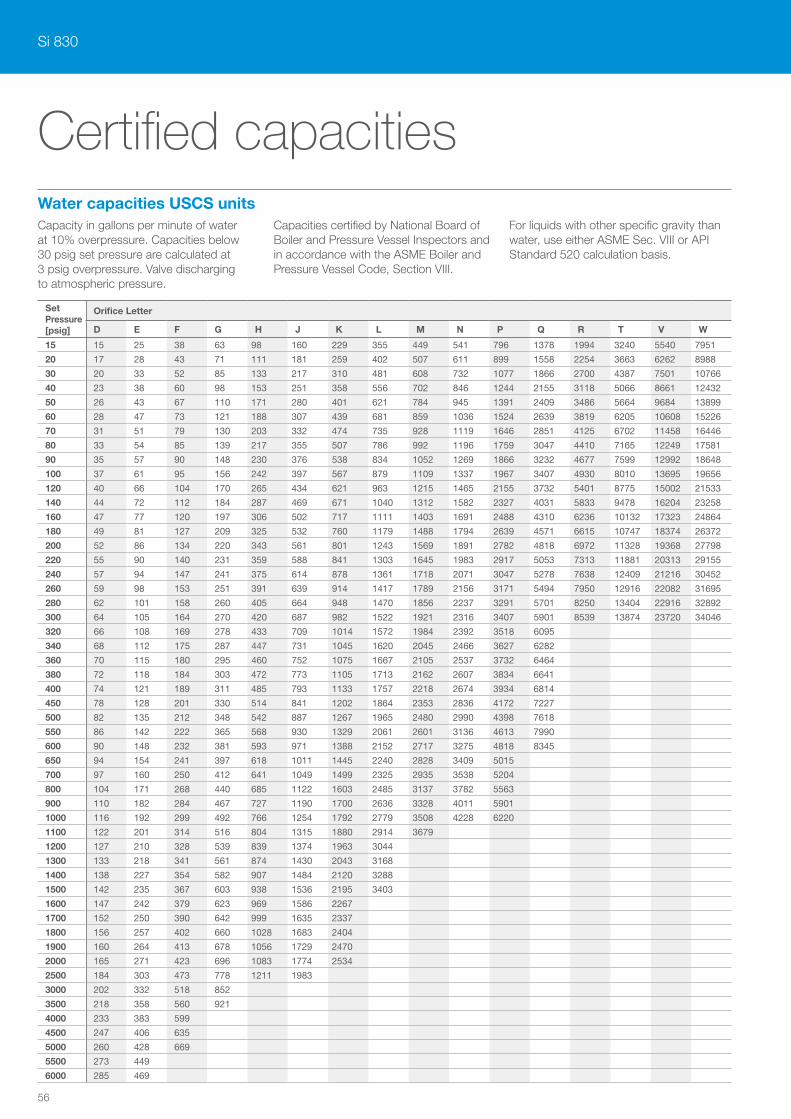
Si 830
56
Set Pressure[psig]
Orifice Letter
D E F G H J K L M N P Q R T V W
15 15 25 38 63 98 160 229 355 449 541 796 1378 1994 3240 5540 7951
20 17 28 43 71 111 181 259 402 507 611 899 1558 2254 3663 6262 8988
30 20 33 52 85 133 217 310 481 608 732 1077 1866 2700 4387 7501 10766
40 23 38 60 98 153 251 358 556 702 846 1244 2155 3118 5066 8661 12432
50 26 43 67 110 171 280 401 621 784 945 1391 2409 3486 5664 9684 13899
60 28 47 73 121 188 307 439 681 859 1036 1524 2639 3819 6205 10608 15226
70 31 51 79 130 203 332 474 735 928 1119 1646 2851 4125 6702 11458 16446
80 33 54 85 139 217 355 507 786 992 1196 1759 3047 4410 7165 12249 17581
90 35 57 90 148 230 376 538 834 1052 1269 1866 3232 4677 7599 12992 18648
100 37 61 95 156 242 397 567 879 1109 1337 1967 3407 4930 8010 13695 19656
120 40 66 104 170 265 434 621 963 1215 1465 2155 3732 5401 8775 15002 21533
140 44 72 112 184 287 469 671 1040 1312 1582 2327 4031 5833 9478 16204 23258
160 47 77 120 197 306 502 717 1111 1403 1691 2488 4310 6236 10132 17323 24864
180 49 81 127 209 325 532 760 1179 1488 1794 2639 4571 6615 10747 18374 26372
200 52 86 134 220 343 561 801 1243 1569 1891 2782 4818 6972 11328 19368 27798
220 55 90 140 231 359 588 841 1303 1645 1983 2917 5053 7313 11881 20313 29155
240 57 94 147 241 375 614 878 1361 1718 2071 3047 5278 7638 12409 21216 30452
260 59 98 153 251 391 639 914 1417 1789 2156 3171 5494 7950 12916 22082 31695
280 62 101 158 260 405 664 948 1470 1856 2237 3291 5701 8250 13404 22916 32892
300 64 105 164 270 420 687 982 1522 1921 2316 3407 5901 8539 13874 23720 34046
320 66 108 169 278 433 709 1014 1572 1984 2392 3518 6095
340 68 112 175 287 447 731 1045 1620 2045 2466 3627 6282
360 70 115 180 295 460 752 1075 1667 2105 2537 3732 6464
380 72 118 184 303 472 773 1105 1713 2162 2607 3834 6641
400 74 121 189 311 485 793 1133 1757 2218 2674 3934 6814
450 78 128 201 330 514 841 1202 1864 2353 2836 4172 7227
500 82 135 212 348 542 887 1267 1965 2480 2990 4398 7618
550 86 142 222 365 568 930 1329 2061 2601 3136 4613 7990
600 90 148 232 381 593 971 1388 2152 2717 3275 4818 8345
650 94 154 241 397 618 1011 1445 2240 2828 3409 5015
700 97 160 250 412 641 1049 1499 2325 2935 3538 5204
800 104 171 268 440 685 1122 1603 2485 3137 3782 5563
900 110 182 284 467 727 1190 1700 2636 3328 4011 5901
1000 116 192 299 492 766 1254 1792 2779 3508 4228 6220
1100 122 201 314 516 804 1315 1880 2914 3679
1200 127 210 328 539 839 1374 1963 3044
1300 133 218 341 561 874 1430 2043 3168
1400 138 227 354 582 907 1484 2120 3288
1500 142 235 367 603 938 1536 2195 3403
1600 147 242 379 623 969 1586 2267
1700 152 250 390 642 999 1635 2337
1800 156 257 402 660 1028 1683 2404
1900 160 264 413 678 1056 1729 2470
2000 165 271 423 696 1083 1774 2534
2500 184 303 473 778 1211 1983
3000 202 332 518 852
3500 218 358 560 921
4000 233 383 599
4500 247 406 635
5000 260 428 669
5500 273 449
6000 285 469
Water capacities USCS unitsCapacity in gallons per minute of water at 10% over pressure. Capacities below 30 psig set pressure are calculated at 3 psig overpressure. Valve discharging to atmospheric pressure.
Capacities certified by National Board of Boiler and Pressure Vessel Inspectors and in accordance with the ASME Boiler and Pressure Vessel Code, Section VIII.
For liquids with other specific gravity than water, use either ASME Sec. VIII or API Standard 520 calculation basis.
Certified capacities

57
Set Pressure[bar g]
Orifice Letter
D E F G H J K L M N P Q R T V W
1 56 91 143 235 366 599 856 1327 1675 2019 2970 5145 7445 12096 20680 29682
2 75 124 193 318 495 810 1157 1794 2265 2730 4016 6957 10067 16356 27964 40137
3 92 151 236 389 605 990 1415 2194 2770 3339 4911 8507 12311 20001 34196 49082
4 106 175 273 449 699 1143 1634 2533 3198 3855 5671 9823 14215 23096 39486 56675
5 119 195 305 502 781 1278 1827 2833 3576 4310 6340 10983 15893 25822 44147 63364
6 130 214 334 550 856 1400 2001 3103 3917 4722 6946 12031 17410 28286 48360 69412
7 140 231 361 594 924 1513 2162 3351 4231 5100 7502 12995 18805 30553 52235 74973
8 150 247 386 635 988 1617 2311 3583 4523 5452 8020 13892 20103 32662 55842 80150
9 159 262 409 673 1048 1715 2451 3800 4797 5783 8507 14735 21322 34643 59229 85012
10 168 276 431 709 1104 1808 2584 4006 5057 6096 8967 15532 22476 36517 62433 89610
11 176 290 453 744 1158 1896 2710 4201 5304 6393 9404 16290 23573 38300 65480 93984
12 184 302 473 777 1210 1981 2830 4388 5539 6678 9822 17014 24621 40003 68392 98163
13 191 315 492 809 1259 2061 2946 4567 5766 6950 10224 17709 25626 41636 71184 102172
14 198 327 510 839 1307 2139 3057 4740 5983 7213 10609 18378 26594 43208 73872 106028
15 205 338 528 869 1353 2214 3164 4906 6193 7466 10982 19023 27527 44724 76464 109750
16 212 349 546 897 1397 2287 3268 5067 6396 7711 11342 19647 28430 46191 78972 113349
17 219 360 563 925 1440 2357 3369 5223 6593 7948 11691 20251 29305 47613 81402 116838
18 225 370 579 952 1482 2426 3466 5374 6784 8178 12030 20838 30154 48993 83762 120225
19 231 381 595 978 1522 2492 3561 5522 6970 8402 12360 21409 30981 50336 86058 123519
20 237 390 610 1003 1562 2557 3654 5665 7151 8621 12681 21966 31786 51643 88293 126728
22 249 410 640 1052 1638 2682 3832 5942 7500 9041 13300 23038
24 260 428 668 1099 1711 2801 4002 6206 7834 9444 13891 24062
26 270 445 696 1144 1781 2915 4166 6459 8154 9829 14458 25045
28 281 462 722 1187 1848 3025 4323 6703 8462 10200 15004 25990
30 290 478 747 1229 1913 3131 4475 6938 8759 10558 15531 26902
35 314 517 807 1327 2066 3382 4833 7494 9460 11404 16775 29058
40 335 552 863 1419 2209 3616 5167 8012 10114 12192 17933 31064
45 356 586 915 1505 2343 3835 5480 8498 10727 12931 19021
50 375 617 965 1586 2470 4043 5777 8957 11307 13631 20050
55 393 648 1012 1664 2590 4240 6059 9394 11859 14296 21029
60 411 676 1057 1738 2705 4429 6328 9812 12386 14932 21964
65 428 704 1100 1809 2816 4609 6587 10213 12892 15541 22861
70 444 731 1141 1877 2922 4783 6835 10598 13379
75 459 756 1182 1943 3025 4951 7075 10970 13849
80 474 781 1220 2007 3124 5114 7307 11330
85 489 805 1258 2068 3220 5271 7532 11679
90 503 828 1294 2128 3313 5424 7751 12017
95 517 851 1330 2187 3404 5572 7963 12347
100 530 873 1364 2244 3493 5717 8170 12667
120 581 957 1495 2458 3826 6263 8950
140 628 1033 1614 2655 4133 6765 9667
160 671 1104 1726 2838 4418 7232
180 712 1171 1830 3010 4686 7670
200 750 1235 1929 3173
220 787 1295 2024 3328
240 822 1353 2114 3476
260 855 1408 2200
280 887 1461 2283
300 919 1512 2363
350 992 1634
400 1061 1746
414 1079 1777
Water capacities SI unitsCapacity in liters per minute of water at 10% over pressure. Capacities below 2.1 bar g set pressure are calculated at 0.21 bar g overpressure. Valve discharging to atmospheric pressure.
Capacities certified by National Board of Boiler and Pressure Vessel Inspectors and in accordance with the ASME Boiler and Pressure Vessel Code, Section VIII.
For liquids with other specific gravity than water, use either ASME Sec. VIII or API Standard 520 calculation basis.
Certified capacities
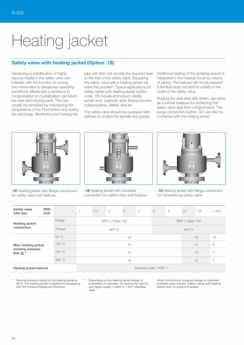
Si 830
58
.18 Heating jacket with flange connection for safety valve with bellows
.18 Heating jacket with threaded connection for safety valve with bellows
.18 Heating jacket with flange connection for conventional safety valve
Heating jacket
Hardening or solidification of highly viscous media in the safety valve can interfere with the function or closing and hence lead to dangerous operating conditions. Media with a tendency to conglutination or crystallization can block the seat and moving parts. This can usually be remedied by maintaining the temperature of the Fluid before and during the discharge. Monitoring and heating the
pipe will often not provide the required heat to the inlet of the safety valve. Equipping the safety valve with a heating jacket will solve this problem. Typical applications for safety valves with heating jacket (option code .18) include ammonium nitrate, acrylic acid, sulphuric acid, fluoropolymers, polypropylene, olefins, and tar.
The safety valve should be equipped with bellows to protect the spindle and guides.
Additional heating of the isolating spacer is integrated in the heating circuit by means of piping. The bellows will not be required if the fluid does not tend to solidify in the outlet of the safety valve.
Purging the seat area with steam can serve as a further measure for protecting the safety valve seat from conglutination. The purge connection (option .32) can also be combined with the heating jacket.
1) Nominal pressure rating for the heating jacket at 50 °C. The heating jacket is labelled in compliance with the Pressure Equipment Directive.
2) Depending on the heating jacket design or availability of materials, we reserve the right to use higher quality 1.4404 or 1.4571 stainless steel.
Other connections, pressure ratings or materials available upon request. Safety valves with heating jacket have no support brackets.
Safety valve Inlet size
NPS Inch
1 1½ 2 3 4 6 8 10 12 ≥ 250
Heating jacket connection
Flange NPS ½ Class 150 NPS 1 Class 150
Thread NPT 3/8 NPT 3/4
Max. heating jacket working pressure [bar g] 1)
50 °C 18 16 10
150 °C 18 14 9
200 °C 18 13 8
300 °C 18 12 7
Heating jacket material Stainless steel 1.4301 2)
Safety valve with heating jacket (Option .18)
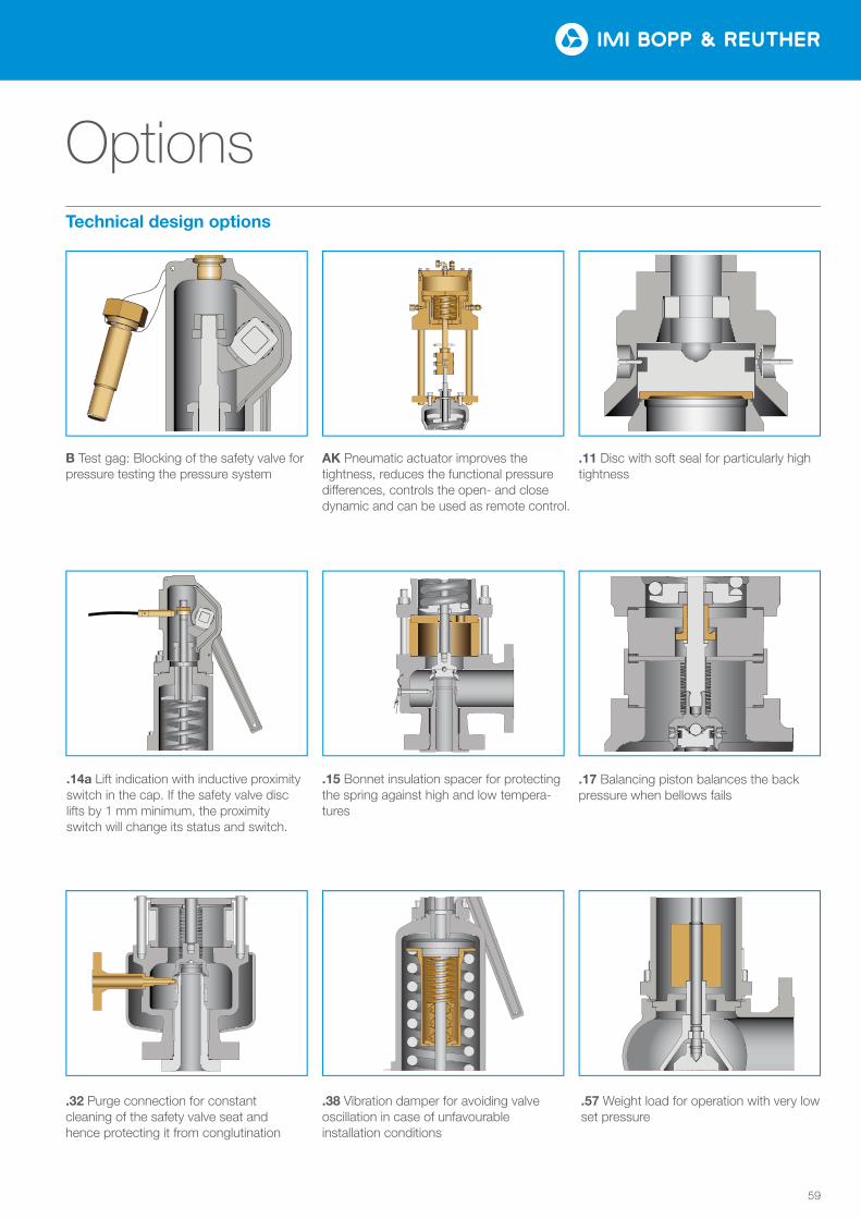
59
Options
B Test gag: Blocking of the safety valve for pressure testing the pressure system
AK Pneumatic actuator improves the tightness, reduces the functional pressure di£erences, controls the open- and close dynamic and can be used as remote control.
.11 Disc with soft seal for particularly high tightness
.57 Weight load for operation with very low set pressure
.38 Vibration damper for avoiding valve oscillation in case of unfavourable installation conditions
.15 Bonnet insulation spacer for protecting the spring against high and low tempera-tures
.17 Balancing piston balances the back pressure when bellows fails
Technical design options
.32 Purge connection for constant cleaning of the safety valve seat and hence protecting it from conglutination
.14a Lift indication with inductive proximity switch in the cap. If the safety valve disc lifts by 1 mm minimum, the proximity switch will change its status and switch.

Tel: +49 (0)621 76220-100 Fax: +49 (0)621 76220-120
www.imi-critical.com [email protected]
IMI Bopp & Reuther Bopp & Reuther Sicherheits- und Regelarmaturen GmbH Carl-Reuther-Straße 1 68305 Mannheim Deutschland
MECESA - Mecánica Egarense S.A.Joan Monpeó 3508223, BarcelonaSpain
Tel: +34 937 363 500Fax: +34 937 832 462
[email protected]@mecesa.com


