Industrial Projects and Technical Services Information Technology SI-Analysis with HSPICE based on IBIS Models Dr. Unger, M. Maurer ATD TD 5 AM Munich, 08.02.98 ibis_summit98.ppt 1 SI-Analysis with HSPICE based on IBIS Models Bernhard Unger and Manfred Maurer Siemens AG Industrial Projects and Technical Services EMC-Support
Transcript
Industrial Projects and Technical ServicesInformation Technology
SI-Analysis with HSPICE based on IBIS Models
Dr. Unger, M. Maurer ATD TD 5 AMMunich, 08.02.98 ibis_summit98.ppt 1
SI-Analysis with HSPICE based on IBIS Models
Bernhard Unger and Manfred MaurerSiemens AG
Industrial Projects and Technical ServicesEMC-Support
SI-Analysis with HSPICE based on IBIS Models
Bernhard Unger and Manfred MaurerSiemens AG
Industrial Projects and Technical ServicesEMC-Support
Industrial Projects and Technical ServicesInformation Technology
SI-Analysis with HSPICE based on IBIS Models
Dr. Unger, M. Maurer ATD TD 5 AMMunich, 08.02.98 ibis_summit98.ppt 2
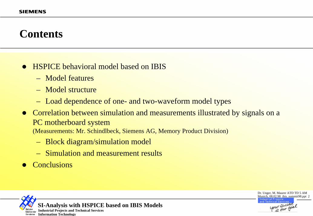
Contents
HSPICE behavioral model based on IBIS– Model features– Model structure– Load dependence of one- and two-waveform model types
Correlation between simulation and measurements illustrated by signals on a PC motherboard system(Measurements: Mr. Schindlbeck, Siemens AG, Memory Product Division)
– Block diagram/simulation model– Simulation and measurement results
Conclusions
Industrial Projects and Technical ServicesInformation Technology
SI-Analysis with HSPICE based on IBIS Models
Dr. Unger, M. Maurer ATD TD 5 AMMunich, 08.02.98 ibis_summit98.ppt 3
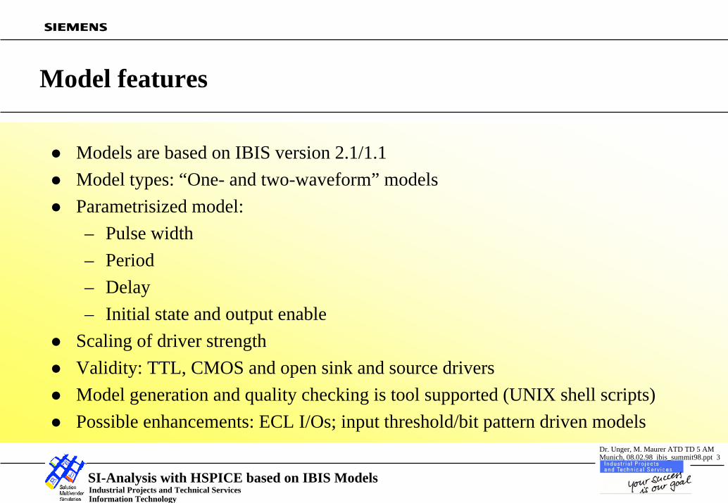
Model features
Models are based on IBIS version 2.1/1.1Model types: “One- and two-waveform” modelsParametrisized model:– Pulse width– Period– Delay– Initial state and output enable
Scaling of driver strengthValidity: TTL, CMOS and open sink and source drivers Model generation and quality checking is tool supported (UNIX shell scripts)Possible enhancements: ECL I/Os; input threshold/bit pattern driven models
Industrial Projects and Technical ServicesInformation Technology
SI-Analysis with HSPICE based on IBIS Models
Dr. Unger, M. Maurer ATD TD 5 AMMunich, 08.02.98 ibis_summit98.ppt 4
Model Structure
IBIS-conform model structure(see for instance: O.Rethmeier, “Modeling of integrated circuits to support SI-analysis”, 12th International Zurich Symposium and Technical Exhibition on Electromagnetic Compatibility, Zurich, February 1997)or: Bob Ross, email concerning ”IBIS TO SPICE DISCUSSION”, IBIS Open Forum, October 27, 1997)
Voltage controlled current sources of polynominal type for pullup and pulldown current source controlVoltage controlled voltage sources of polynominal type for timing controlParameter driven setting of initial conditions to overcome convergence problemsGeneration of multipliers kpu(t), kpd(t) by HSPICE runs
Industrial Projects and Technical ServicesInformation Technology
SI-Analysis with HSPICE based on IBIS Models
Dr. Unger, M. Maurer ATD TD 5 AMMunich, 08.02.98 ibis_summit98.ppt 5
kpu(t) *Ipu(Vout)
kpd(t) *Ipd(Vout)
Ipc
Igc
C_comp/2
C_comp/2
OUT
GND
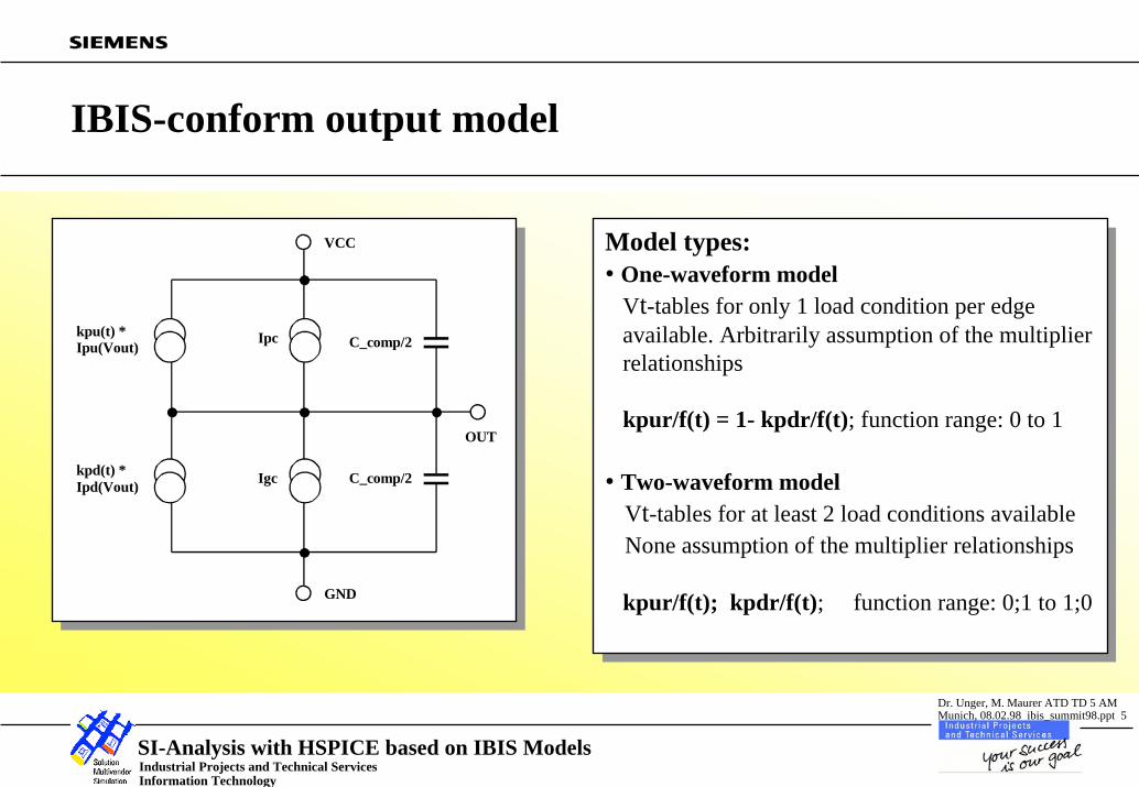
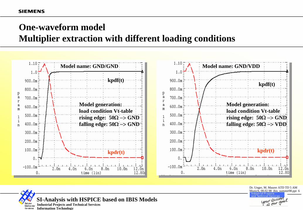
VCC Model types:• One-waveform model
Vt-tables for only 1 load condition per edge available. Arbitrarily assumption of the multiplier relationships
kpur/f(t) = 1- kpdr/f(t); function range: 0 to 1
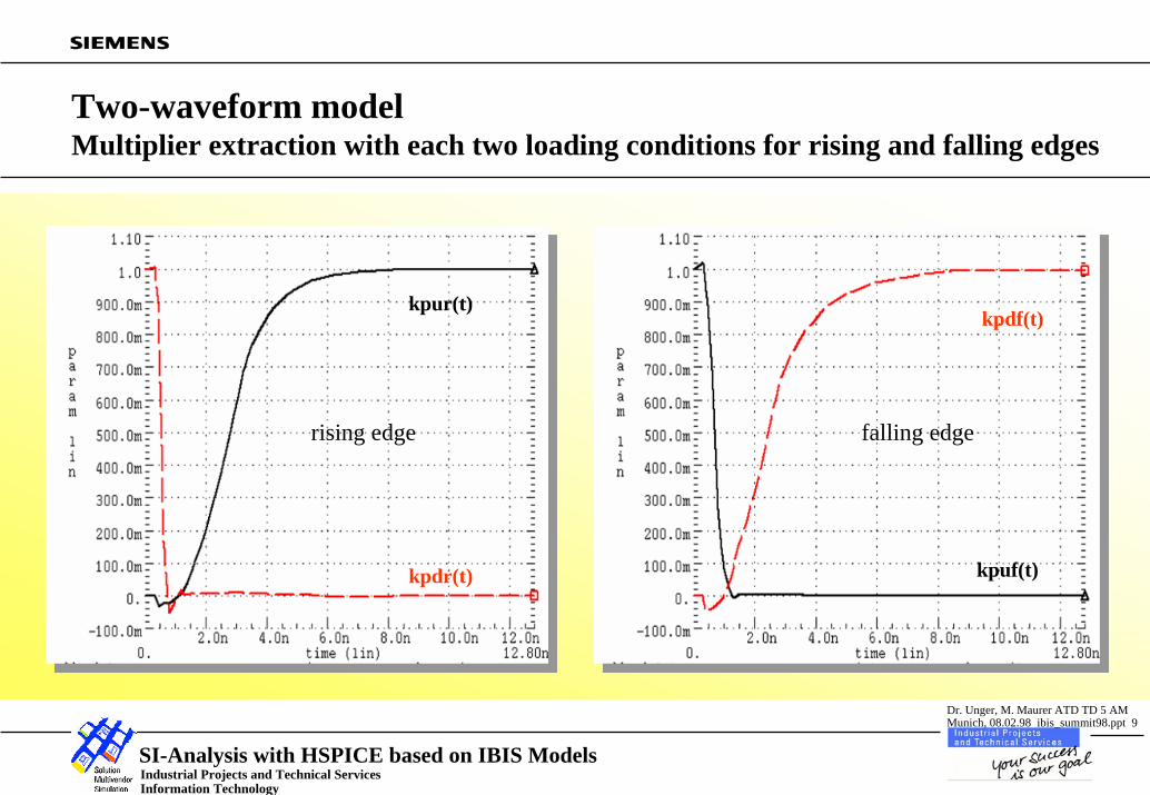
• Two-waveform modelVt-tables for at least 2 load conditions availableNone assumption of the multiplier relationships
kpur/f(t); kpdr/f(t); function range: 0;1 to 1;0
IBIS-conform output model
Model types:• One-waveform model
Vt-tables for only 1 load condition per edge available. Arbitrarily assumption of the multiplier relationships
kpur/f(t) = 1- kpdr/f(t); function range: 0 to 1
• Two-waveform modelVt-tables for at least 2 load conditions availableNone assumption of the multiplier relationships
kpur/f(t); kpdr/f(t); function range: 0;1 to 1;0
Industrial Projects and Technical ServicesInformation Technology
SI-Analysis with HSPICE based on IBIS Models
Dr. Unger, M. Maurer ATD TD 5 AMMunich, 08.02.98 ibis_summit98.ppt 6
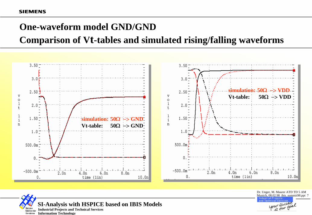
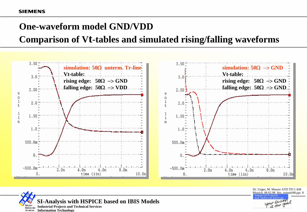
One-waveform modelMultiplier extraction with different loading conditions
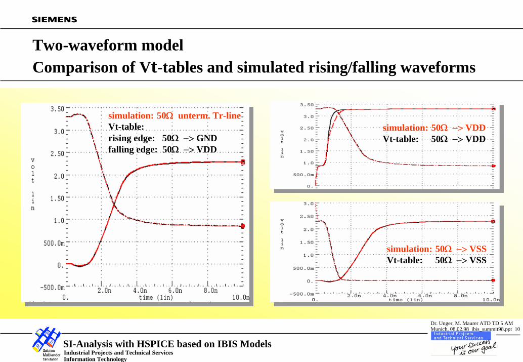
Two-waveform model Comparison of Vt-tables and simulated rising/falling waveforms
simulation: 50Ω −> VDDVt-table: 50Ω −> VDD
simulation: 50Ω −> VSSVt-table: 50Ω −> VSS
Industrial Projects and Technical ServicesInformation Technology
SI-Analysis with HSPICE based on IBIS Models
Dr. Unger, M. Maurer ATD TD 5 AMMunich, 08.02.98 ibis_summit98.ppt 11
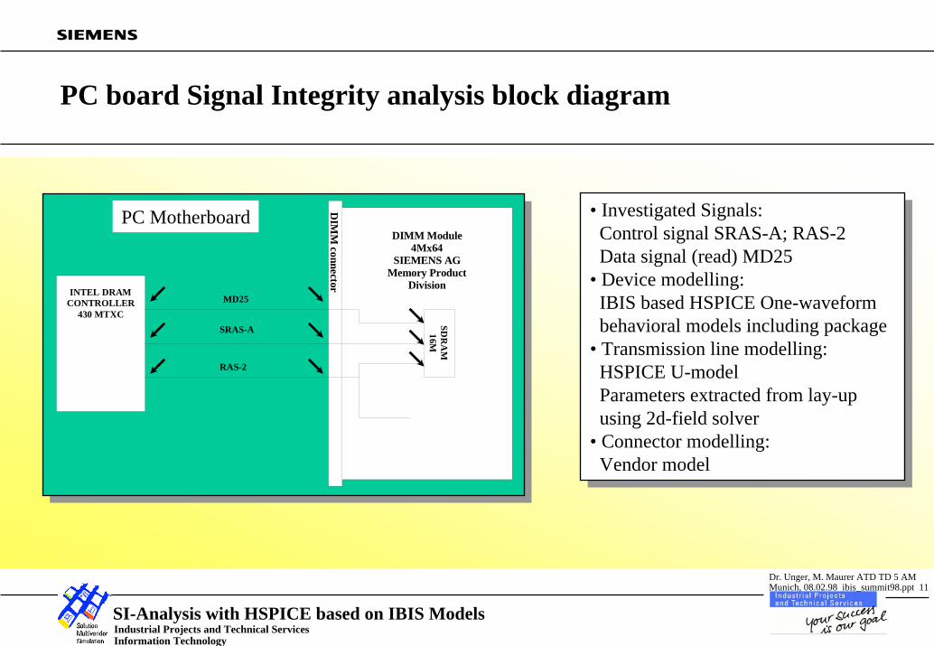
DIMM Module4Mx64
SIEMENS AGMemory Product
DivisionINTEL DRAM
CONTROLLER430 MTXC
SDR
AM
16M
DIM
M connector
SRAS-A
RAS-2
MD25
PC board Signal Integrity analysis block diagram
PC Motherboard • Investigated Signals:Control signal SRAS-A; RAS-2Data signal (read) MD25
• Device modelling:IBIS based HSPICE One-waveform behavioral models including package
• Transmission line modelling:HSPICE U-modelParameters extracted from lay-upusing 2d-field solver
• Connector modelling:Vendor model
• Investigated Signals:Control signal SRAS-A; RAS-2Data signal (read) MD25
• Device modelling:IBIS based HSPICE One-waveform behavioral models including package
• Transmission line modelling:HSPICE U-modelParameters extracted from lay-upusing 2d-field solver
• Connector modelling:Vendor model
Industrial Projects and Technical ServicesInformation Technology
SI-Analysis with HSPICE based on IBIS Models
Dr. Unger, M. Maurer ATD TD 5 AMMunich, 08.02.98 ibis_summit98.ppt 12
Signal SRAS-A: MTXC model v1t (50Ω−>GND; 50Ω−>GND)rising edge
Behavioral model generationbase model CAx_v1t:rising edge: V_fix=0.0V;R_fix=50Ωfalling edge: V_fix=0.0V;R_fix=50Ω
• Transmitter MTXC:MeasurementSimulation
• DIMM Connector:MeasurementSimulation
• Receiver SDRAM:MeasurementSimulation
• Transmitter MTXC:MeasurementSimulation
• DIMM Connector:MeasurementSimulation
• Receiver SDRAM:MeasurementSimulation
Industrial Projects and Technical ServicesInformation Technology
SI-Analysis with HSPICE based on IBIS Models
Dr. Unger, M. Maurer ATD TD 5 AMMunich, 08.02.98 ibis_summit98.ppt 13
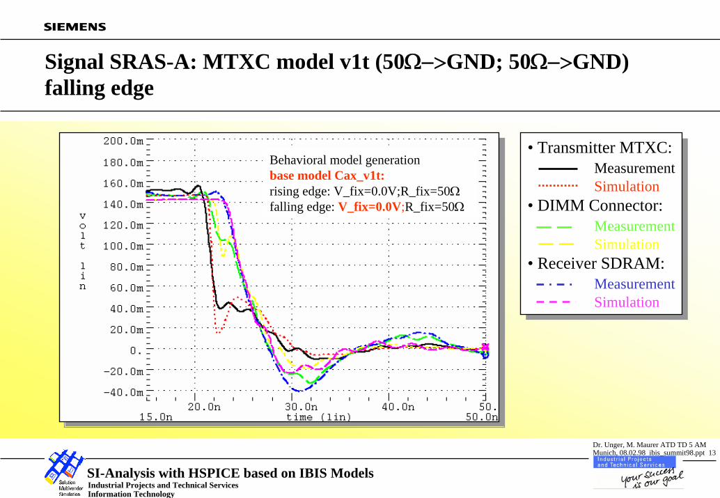
Signal SRAS-A: MTXC model v1t (50Ω−>GND; 50Ω−>GND) falling edge
Behavioral model generationbase model Cax_v1t:rising edge: V_fix=0.0V;R_fix=50Ωfalling edge: V_fix=0.0V;R_fix=50Ω
• Transmitter MTXC:MeasurementSimulation
• DIMM Connector:MeasurementSimulation
• Receiver SDRAM:MeasurementSimulation
• Transmitter MTXC:MeasurementSimulation
• DIMM Connector:MeasurementSimulation
• Receiver SDRAM:MeasurementSimulation
Industrial Projects and Technical ServicesInformation Technology
SI-Analysis with HSPICE based on IBIS Models
Dr. Unger, M. Maurer ATD TD 5 AMMunich, 08.02.98 ibis_summit98.ppt 14
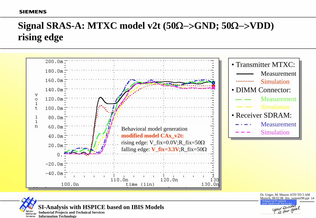
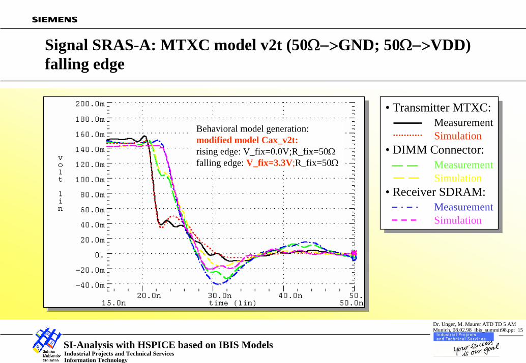
Signal SRAS-A: MTXC model v2t (50Ω−>GND; 50Ω−>VDD) rising edge
Behavioral model generationmodified model CAx_v2t:rising edge: V_fix=0.0V;R_fix=50Ωfalling edge: V_fix=3.3V;R_fix=50Ω
• Transmitter MTXC:MeasurementSimulation
• DIMM Connector:MeasurementSimulation
• Receiver SDRAM:MeasurementSimulation
• Transmitter MTXC:MeasurementSimulation
• DIMM Connector:MeasurementSimulation
• Receiver SDRAM:MeasurementSimulation
Industrial Projects and Technical ServicesInformation Technology
SI-Analysis with HSPICE based on IBIS Models
Dr. Unger, M. Maurer ATD TD 5 AMMunich, 08.02.98 ibis_summit98.ppt 15
Signal SRAS-A: MTXC model v2t (50Ω−>GND; 50Ω−>VDD) falling edge
Behavioral model generation:modified model Cax_v2t:rising edge: V_fix=0.0V;R_fix=50Ωfalling edge: V_fix=3.3V;R_fix=50Ω
• Transmitter MTXC:MeasurementSimulation
• DIMM Connector:MeasurementSimulation
• Receiver SDRAM:MeasurementSimulation
• Transmitter MTXC:MeasurementSimulation
• DIMM Connector:MeasurementSimulation
• Receiver SDRAM:MeasurementSimulation
Industrial Projects and Technical ServicesInformation Technology
SI-Analysis with HSPICE based on IBIS Models
Dr. Unger, M. Maurer ATD TD 5 AMMunich, 08.02.98 ibis_summit98.ppt 16
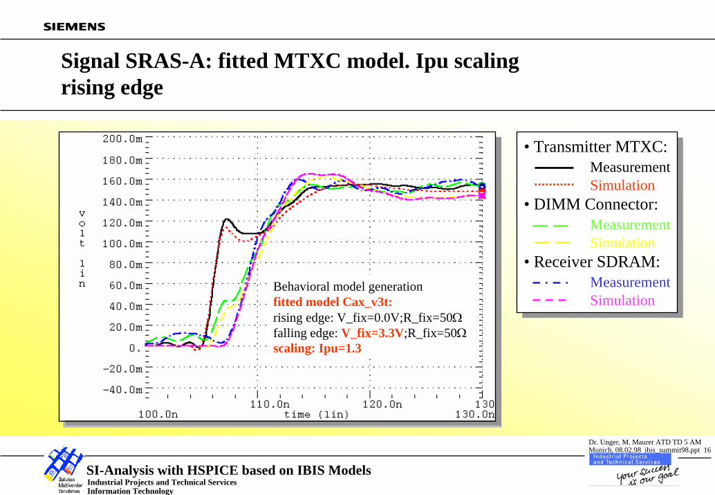
Signal SRAS-A: fitted MTXC model. Ipu scalingrising edge
Behavioral model generationfitted model Cax_v3t:rising edge: V_fix=0.0V;R_fix=50Ωfalling edge: V_fix=3.3V;R_fix=50Ωscaling: Ipu=1.3
• Transmitter MTXC:MeasurementSimulation
• DIMM Connector:MeasurementSimulation
• Receiver SDRAM:MeasurementSimulation
• Transmitter MTXC:MeasurementSimulation
• DIMM Connector:MeasurementSimulation
• Receiver SDRAM:MeasurementSimulation
Industrial Projects and Technical ServicesInformation Technology
SI-Analysis with HSPICE based on IBIS Models
Dr. Unger, M. Maurer ATD TD 5 AMMunich, 08.02.98 ibis_summit98.ppt 17
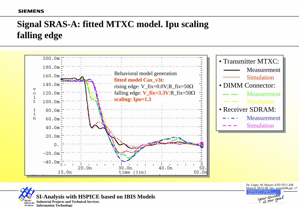
Signal SRAS-A: fitted MTXC model. Ipu scaling falling edge
Behavioral model generationfitted model Cax_v3t:rising edge: V_fix=0.0V;R_fix=50Ωfalling edge: V_fix=3.3V;R_fix=50Ωscaling: Ipu=1.3
• Transmitter MTXC:MeasurementSimulation
• DIMM Connector:MeasurementSimulation
• Receiver SDRAM:MeasurementSimulation
• Transmitter MTXC:MeasurementSimulation
• DIMM Connector:MeasurementSimulation
• Receiver SDRAM:MeasurementSimulation
Industrial Projects and Technical ServicesInformation Technology
SI-Analysis with HSPICE based on IBIS Models
Dr. Unger, M. Maurer ATD TD 5 AMMunich, 08.02.98 ibis_summit98.ppt 18
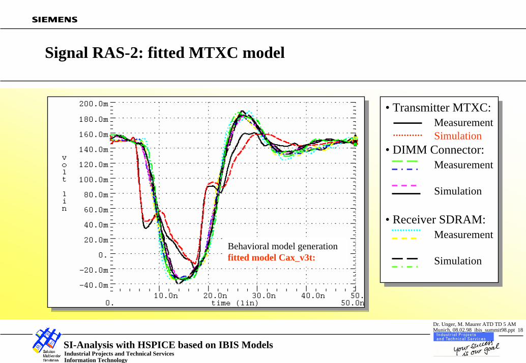
Signal RAS-2: fitted MTXC model
Behavioral model generationfitted model Cax_v3t:
• Transmitter MTXC:MeasurementSimulation
• DIMM Connector:Measurement
Simulation
• Receiver SDRAM:Measurement
Simulation
• Transmitter MTXC:MeasurementSimulation
• DIMM Connector:Measurement
Simulation
• Receiver SDRAM:Measurement
Simulation
Industrial Projects and Technical ServicesInformation Technology
SI-Analysis with HSPICE based on IBIS Models
Dr. Unger, M. Maurer ATD TD 5 AMMunich, 08.02.98 ibis_summit98.ppt 19
Signal MD25 read: SDRAM model (50Ω−>GND/10pF; 50Ω−>VDD/10pF)
• Transmitter SDRAM:MeasurementSimulation
• DIMM Connector:MeasurementSimulation
• Receiver MTXC:MeasurementSimulation
• Transmitter SDRAM:MeasurementSimulation
• DIMM Connector:MeasurementSimulation
• Receiver MTXC:MeasurementSimulation
Industrial Projects and Technical ServicesInformation Technology
SI-Analysis with HSPICE based on IBIS Models
Dr. Unger, M. Maurer ATD TD 5 AMMunich, 08.02.98 ibis_summit98.ppt 20
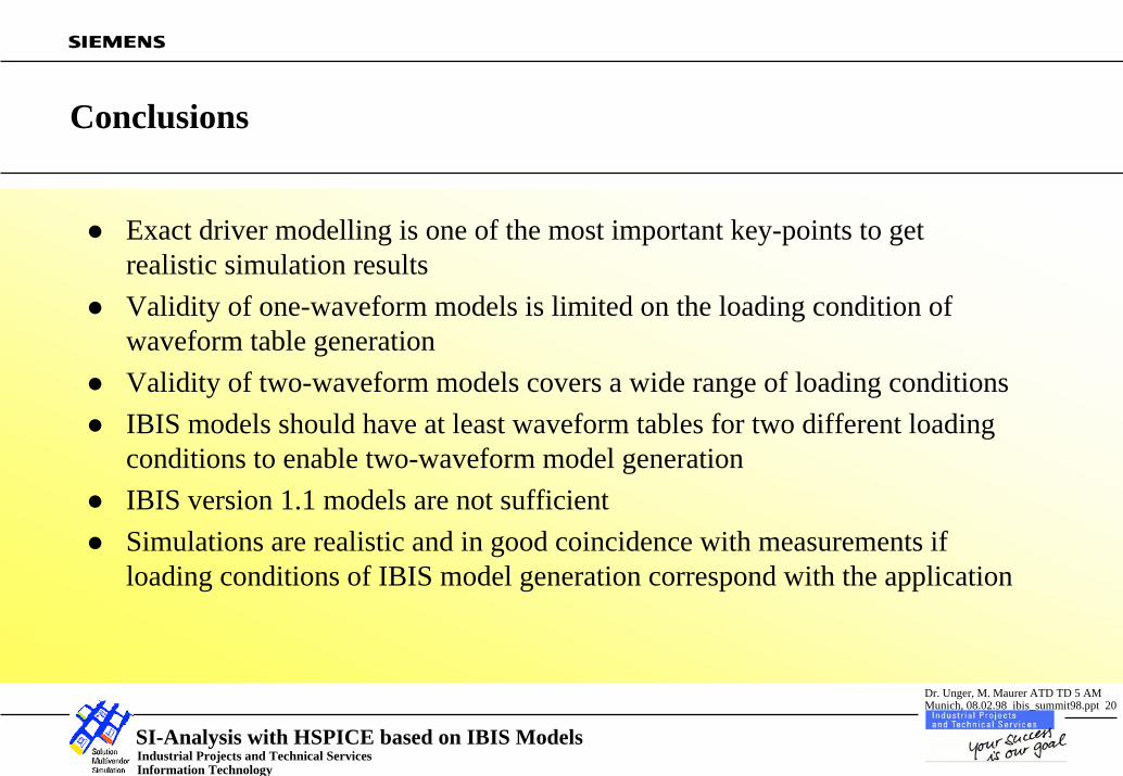
Conclusions
Exact driver modelling is one of the most important key-points to get realistic simulation resultsValidity of one-waveform models is limited on the loading condition of waveform table generationValidity of two-waveform models covers a wide range of loading conditionsIBIS models should have at least waveform tables for two different loading conditions to enable two-waveform model generationIBIS version 1.1 models are not sufficientSimulations are realistic and in good coincidence with measurements if loading conditions of IBIS model generation correspond with the application