59
ISO TC22/SC41 Specific aspects for gaseous fuels Paul Dijkhof Kiwa Nederland B.V., Apeldoorn, The Netherlands
ISO TC22/SC41 Specific aspects for gaseous fuels Paul Dijkhof Kiwa Nederland B.V., Apeldoorn, The Netherlands
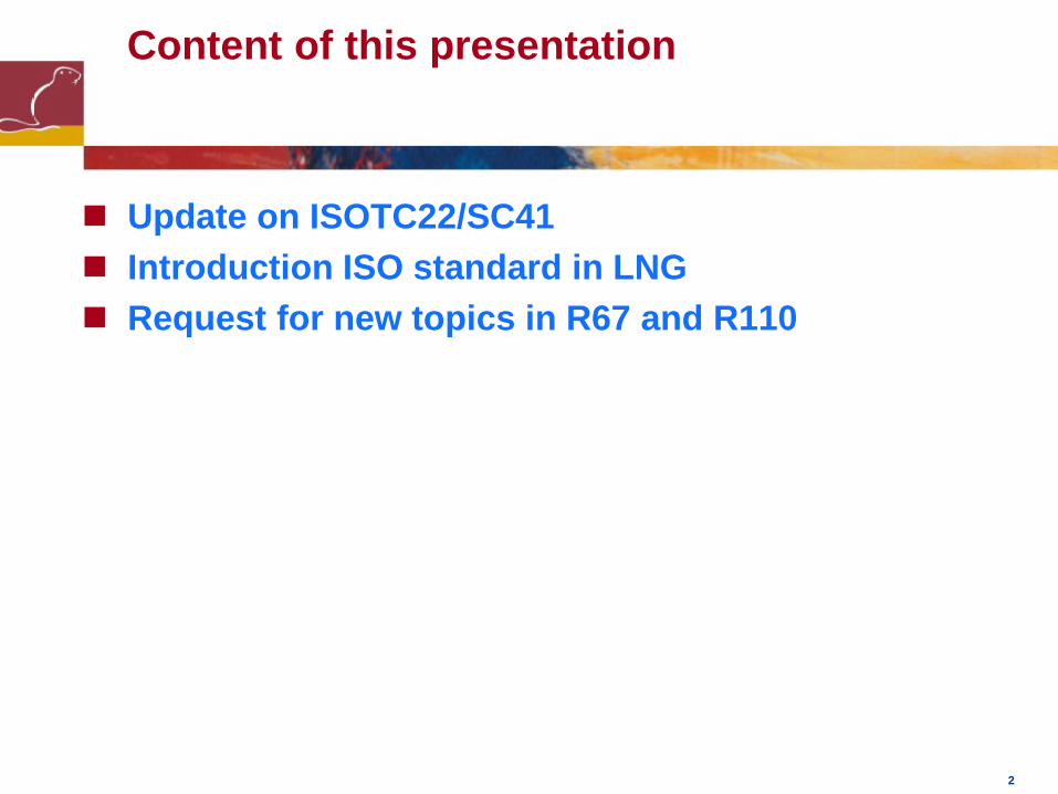
Content of this presentation
Update on ISOTC22/SC41 Introduction ISO standard in LNG Request for new topics in R67 and R110
2
3
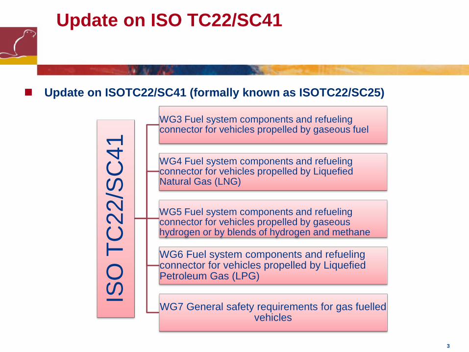
Update on ISO TC22/SC41
Update on ISOTC22/SC41 (formally known as ISOTC22/SC25)
IS
O T
C22
/SC
41 WG3 Fuel system components and refueling
connector for vehicles propelled by gaseous fuel
WG4 Fuel system components and refueling connector for vehicles propelled by Liquefied Natural Gas (LNG)
WG5 Fuel system components and refueling connector for vehicles propelled by gaseous hydrogen or by blends of hydrogen and methane
WG6 Fuel system components and refueling connector for vehicles propelled by Liquefied Petroleum Gas (LPG)
WG7 General safety requirements for gas fuelled vehicles
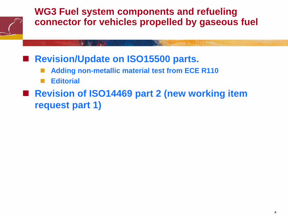
WG3 Fuel system components and refueling connector for vehicles propelled by gaseous fuel
Revision/Update on ISO15500 parts. Adding non-metallic material test from ECE R110 Editorial
Revision of ISO14469 part 2 (new working item request part 1)
4
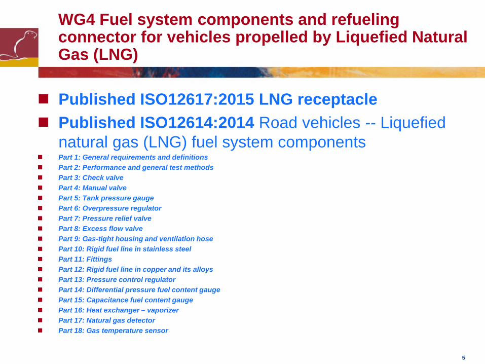
WG4 Fuel system components and refueling connector for vehicles propelled by Liquefied Natural Gas (LNG)
Published ISO12617:2015 LNG receptacle Published ISO12614:2014 Road vehicles -- Liquefied
natural gas (LNG) fuel system components Part 1: General requirements and definitions Part 2: Performance and general test methods Part 3: Check valve Part 4: Manual valve Part 5: Tank pressure gauge Part 6: Overpressure regulator Part 7: Pressure relief valve Part 8: Excess flow valve Part 9: Gas-tight housing and ventilation hose Part 10: Rigid fuel line in stainless steel Part 11: Fittings Part 12: Rigid fuel line in copper and its alloys Part 13: Pressure control regulator Part 14: Differential pressure fuel content gauge Part 15: Capacitance fuel content gauge Part 16: Heat exchanger – vaporizer Part 17: Natural gas detector Part 18: Gas temperature sensor
5
WG5 Fuel system components and refueling connector for vehicles propelled by gaseous hydrogen or by blends of hydrogen and methane
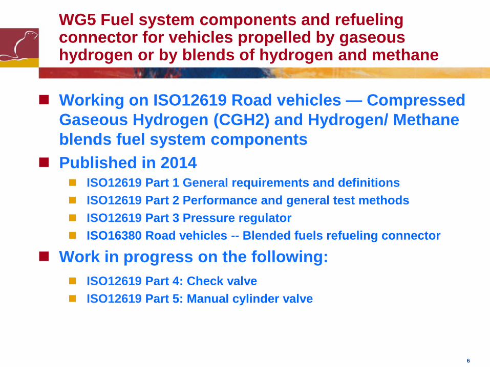
Working on ISO12619 Road vehicles — Compressed Gaseous Hydrogen (CGH2) and Hydrogen/ Methane blends fuel system components
Published in 2014 ISO12619 Part 1 General requirements and definitions ISO12619 Part 2 Performance and general test methods ISO12619 Part 3 Pressure regulator ISO16380 Road vehicles -- Blended fuels refueling connector
Work in progress on the following: ISO12619 Part 4: Check valve ISO12619 Part 5: Manual cylinder valve
6
WG6 Fuel system components and refueling connector for vehicles propelled by Liquefied Petroleum Gas (LPG)
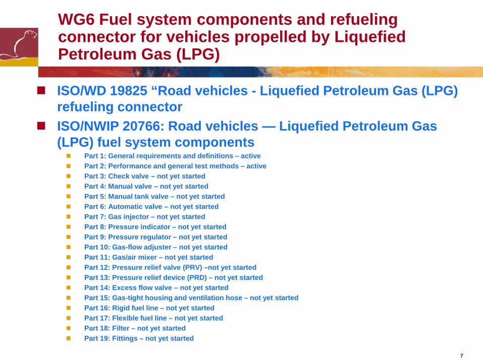
ISO/WD 19825 “Road vehicles - Liquefied Petroleum Gas (LPG) refueling connector
ISO/NWIP 20766: Road vehicles — Liquefied Petroleum Gas (LPG) fuel system components Part 1: General requirements and definitions – active Part 2: Performance and general test methods – active Part 3: Check valve – not yet started Part 4: Manual valve – not yet started Part 5: Manual tank valve – not yet started Part 6: Automatic valve – not yet started Part 7: Gas injector – not yet started Part 8: Pressure indicator – not yet started Part 9: Pressure regulator – not yet started Part 10: Gas-flow adjuster – not yet started Part 11: Gas/air mixer – not yet started Part 12: Pressure relief valve (PRV) –not yet started Part 13: Pressure relief device (PRD) – not yet started Part 14: Excess flow valve – not yet started Part 15: Gas-tight housing and ventilation hose – not yet started Part 16: Rigid fuel line – not yet started Part 17: Flexible fuel line – not yet started Part 18: Filter – not yet started Part 19: Fittings – not yet started
7
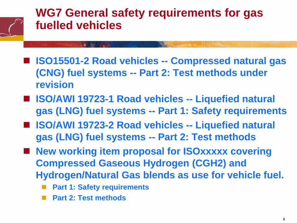
WG7 General safety requirements for gas fuelled vehicles
ISO15501-2 Road vehicles -- Compressed natural gas (CNG) fuel systems -- Part 2: Test methods under revision
ISO/AWI 19723-1 Road vehicles -- Liquefied natural gas (LNG) fuel systems -- Part 1: Safety requirements
ISO/AWI 19723-2 Road vehicles -- Liquefied natural gas (LNG) fuel systems -- Part 2: Test methods
New working item proposal for ISOxxxxx covering Compressed Gaseous Hydrogen (CGH2) and Hydrogen/Natural Gas blends as use for vehicle fuel. Part 1: Safety requirements Part 2: Test methods
8
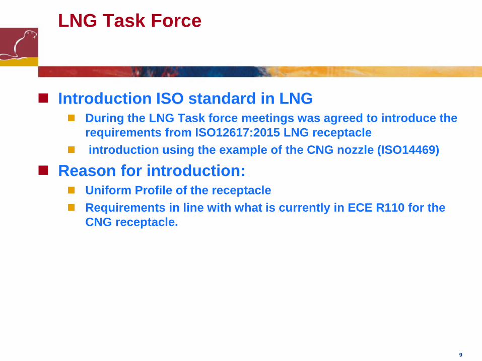
LNG Task Force
Introduction ISO standard in LNG During the LNG Task force meetings was agreed to introduce the
requirements from ISO12617:2015 LNG receptacle introduction using the example of the CNG nozzle (ISO14469)
Reason for introduction: Uniform Profile of the receptacle Requirements in line with what is currently in ECE R110 for the
CNG receptacle.
9
Request for new topics in R67
Request from OEM to update the R67 requirements on the fuel line and welding requirement. (see next sheets for explanation)
10
GME Engineering
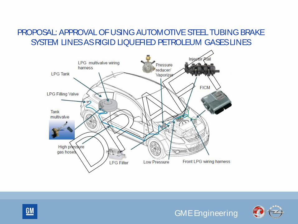
PROPOSAL: APPROVAL OF USING AUTOMOTIVE STEEL TUBING BRAKESYSTEM LINES AS RIGID LIQUEFIED PETROLEUM GASES LINES
DRAFT
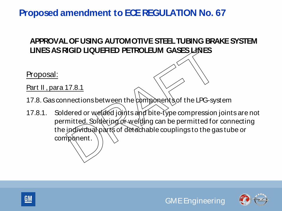
Proposed amendment to ECE REGULATION No. 67
APPROVAL OF USING AUTOMOTIVE STEEL TUBING BRAKE SYSTEMLINES AS RIGID LIQUEFIED PETROLEUM GASES LINES
Proposal:
Part II , para 17.8.1
17.8. Gas connections between the components of the LPG-system
17.8.1. Soldered or welded joints and bite-type compression joints are notpermitted. Soldering or welding can be permitted for connectingthe individual parts of detachable couplings to the gas tube orcomponent.
GME Engineering
DRAFT
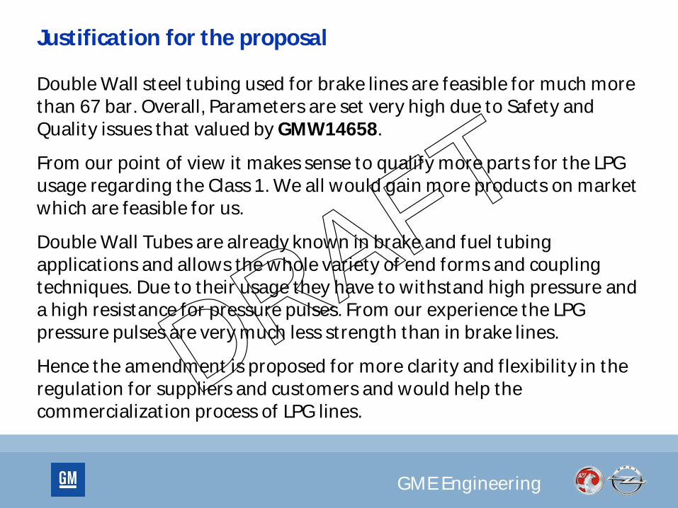
Justification for the proposal
Double Wall steel tubing used for brake lines are feasible for much morethan 67 bar. Overall, Parameters are set very high due to Safety andQuality issues that valued by GMW14658.
From our point of view it makes sense to qualify more parts for the LPGusage regarding the Class 1. We all would gain more products on marketwhich are feasible for us.
Double Wall Tubes are already known in brake and fuel tubingapplications and allows the whole variety of end forms and couplingtechniques. Due to their usage they have to withstand high pressure anda high resistance for pressure pulses. From our experience the LPGpressure pulses are very much less strength than in brake lines.
Hence the amendment is proposed for more clarity and flexibility in theregulation for suppliers and customers and would help thecommercialization process of LPG lines.
GME Engineering
DRAFT
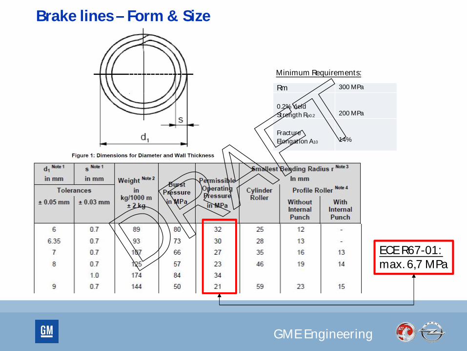
Brake lines – Form & Size
GME Engineering
Rm 300 MPa
0.2% YieldStrength Rp0.2 200 MPa
FractureElongation A10 14%
Minimum Requirements:
ECE R67-01:max. 6,7 MPaDRAFT
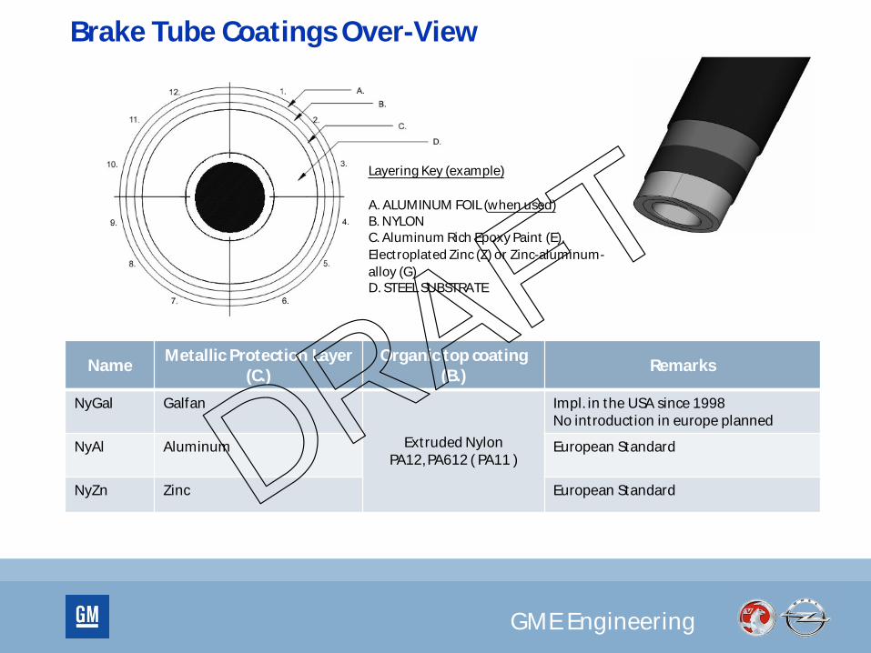
Brake Tube Coatings Over-View
NameMetallic Protection Layer
(C.)Organic top coating
(B.)Remarks
NyGal Galfan
Extruded NylonPA12, PA612 ( PA11 )
Impl. in the USA since 1998No introduction in europe planned
NyAl Aluminum European Standard
NyZn Zinc European Standard
GME Engineering
Layering Key (example)
A. ALUMINUM FOIL (when used)B. NYLONC. Aluminum Rich Epoxy Paint (E),Electroplated Zinc (Z) or Zinc-aluminum-alloy (G)D. STEEL SUBSTRATE
DRAFT
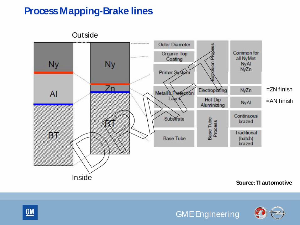
Process Mapping-Brake lines
GME Engineering
=AN finish
=ZN finish
Inside
Outside
Source: TI automotive
DRAFT
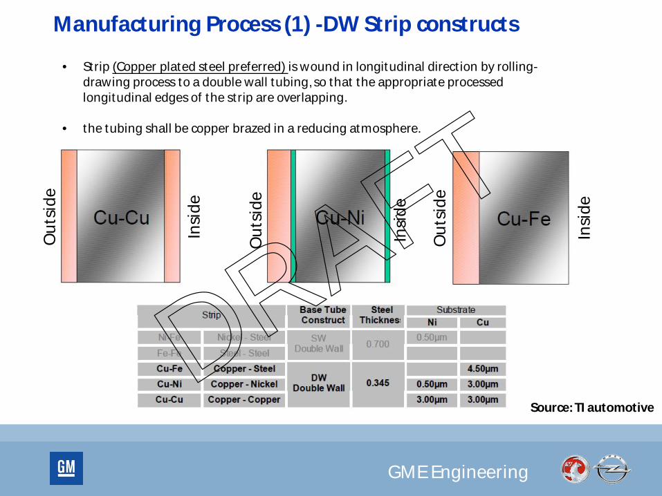
Manufacturing Process (1) -DW Strip constructs
GME Engineering
• Strip (Copper plated steel preferred) is wound in longitudinal direction by rolling-drawing process to a double wall tubing, so that the appropriate processedlongitudinal edges of the strip are overlapping.
• the tubing shall be copper brazed in a reducing atmosphere.
Insi
de
Ou
tsid
e
Insi
de
Ou
tsid
e
Insi
de
Ou
tsid
e
Source: TI automotive
DRAFT
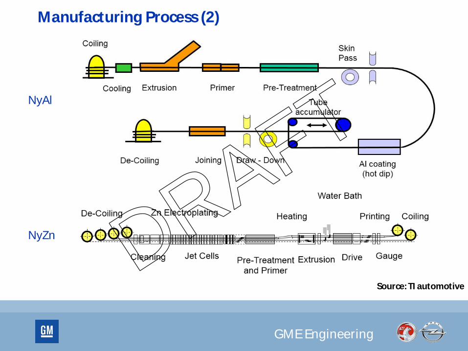
Manufacturing Process (2)
GME Engineering
NyZn
NyAl
Source: TI automotive
DRAFT
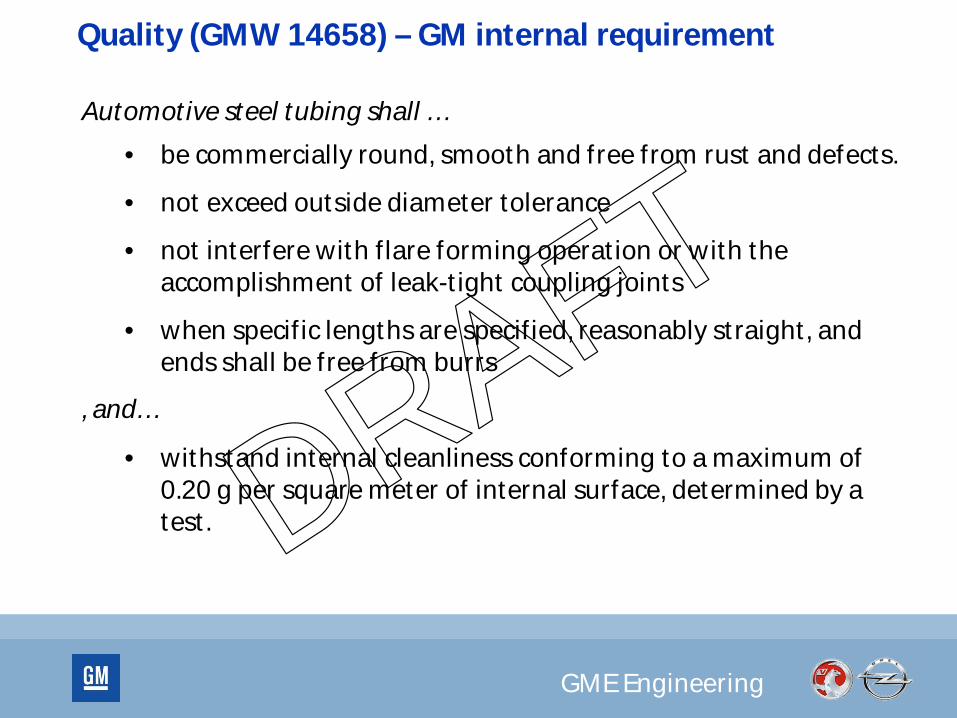
Quality (GMW 14658) – GM internal requirement
• be commercially round, smooth and free from rust and defects.
• not exceed outside diameter tolerance
• not interfere with flare forming operation or with theaccomplishment of leak-tight coupling joints
• when specific lengths are specified, reasonably straight, andends shall be free from burrs
• withstand internal cleanliness conforming to a maximum of0.20 g per square meter of internal surface, determined by atest.
GME Engineering
Automotive steel tubing shall …
, and…
DRAFT
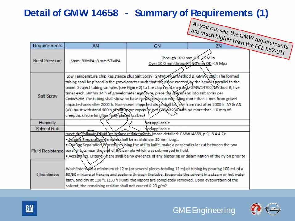
Detail of GMW 14658 - Summary of Requirements (1)
GME Engineering
DRAFT
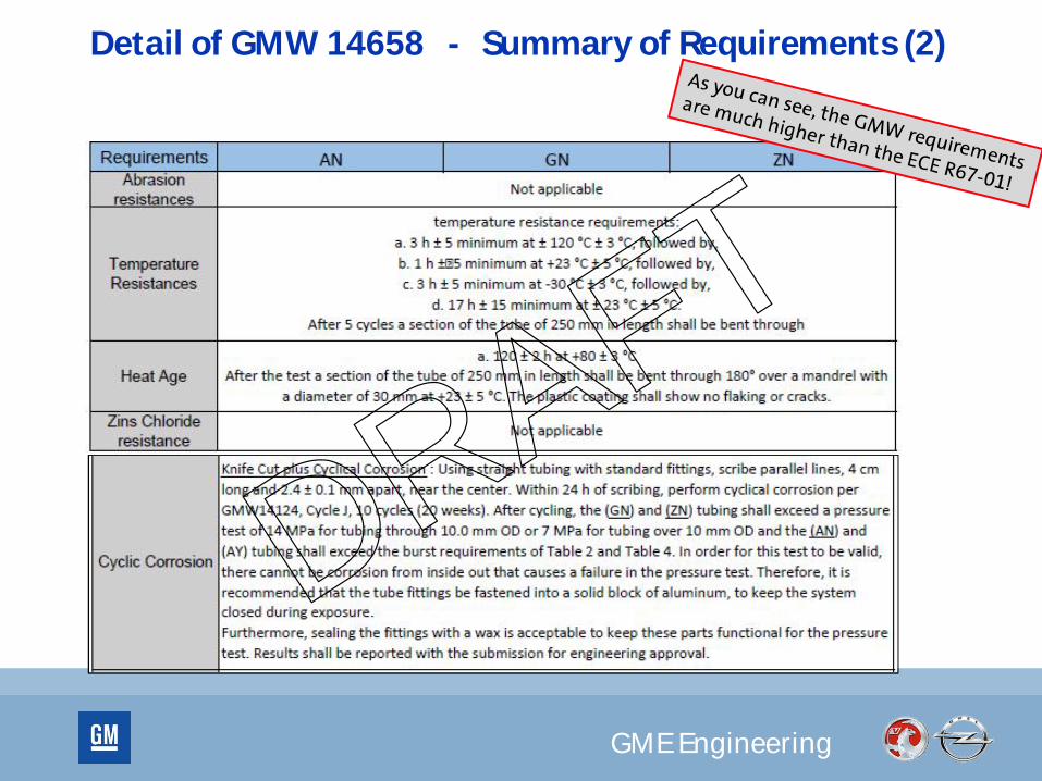
Detail of GMW 14658 - Summary of Requirements (2)
GME Engineering
DRAFT
Request for new topics in R110
Request from OEM to update the ECE R110 with the following changes on couplings of hoses.
11
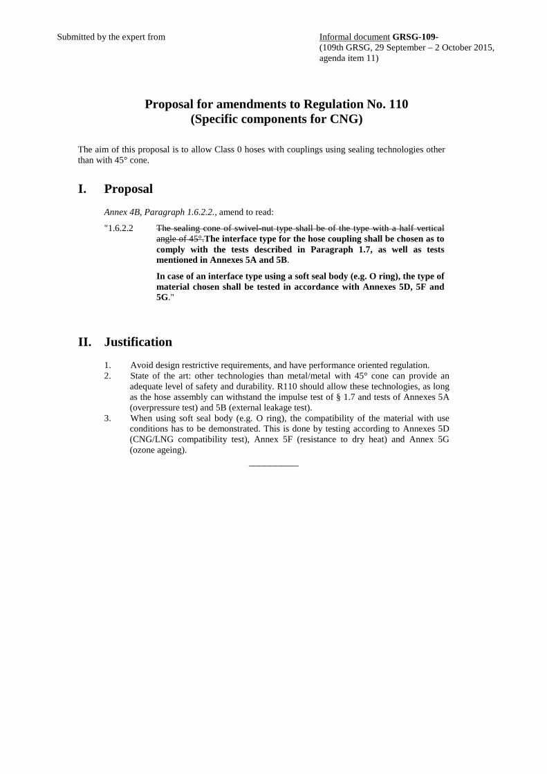
Submitted by the expert from Informal document GRSG-109- (109th GRSG, 29 September – 2 October 2015, agenda item 11)
Proposal for amendments to Regulation No. 110 (Specific components for CNG)
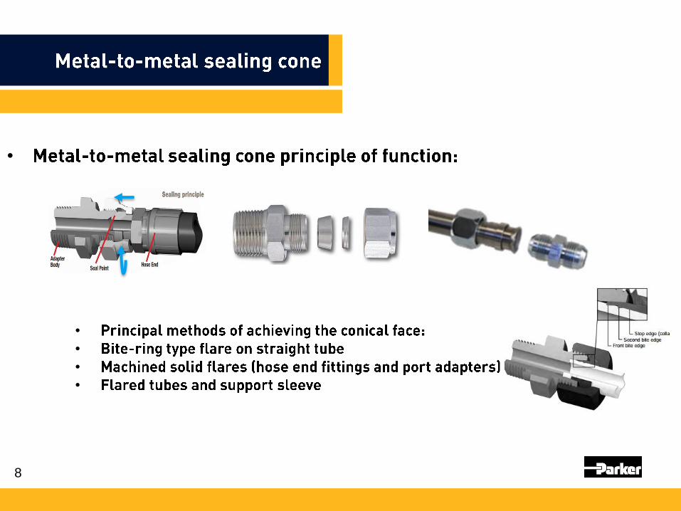
The aim of this proposal is to allow Class 0 hoses with couplings using sealing technologies other than with 45° cone.
I. Proposal
Annex 4B, Paragraph 1.6.2.2., amend to read:
"1.6.2.2 The sealing cone of swivel-nut type shall be of the type with a half vertical angle of 45°.The interface type for the hose coupling shall be chosen as to comply with the tests described in Paragraph 1.7, as well as tests mentioned in Annexes 5A and 5B.
In case of an interface type using a soft seal body (e.g. O ring), the type of material chosen shall be tested in accordance with Annexes 5D, 5F and 5G."
II. Justification
1. Avoid design restrictive requirements, and have performance oriented regulation. 2. State of the art: other technologies than metal/metal with 45° cone can provide an
adequate level of safety and durability. R110 should allow these technologies, as long as the hose assembly can withstand the impulse test of § 1.7 and tests of Annexes 5A (overpressure test) and 5B (external leakage test).
3. When using soft seal body (e.g. O ring), the compatibility of the material with use conditions has to be demonstrated. This is done by testing according to Annexes 5D (CNG/LNG compatibility test), Annex 5F (resistance to dry heat) and Annex 5G (ozone ageing).
_________

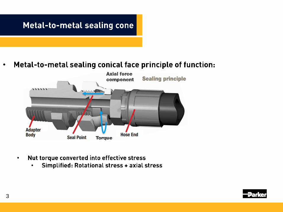
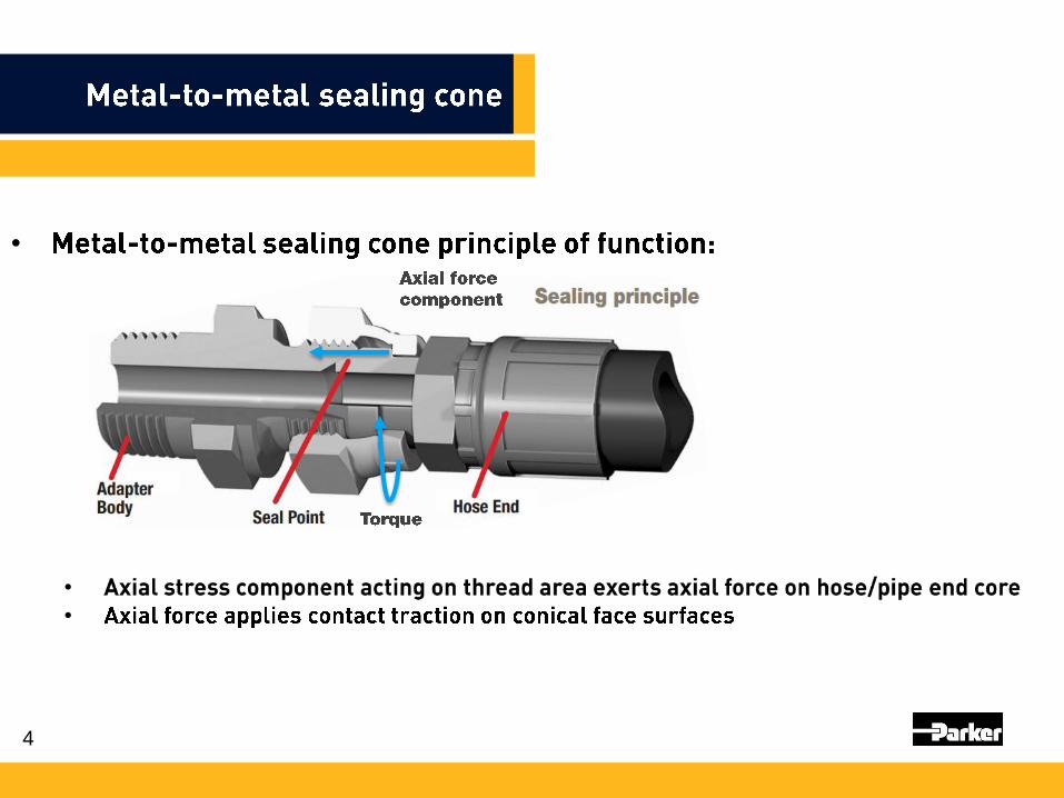
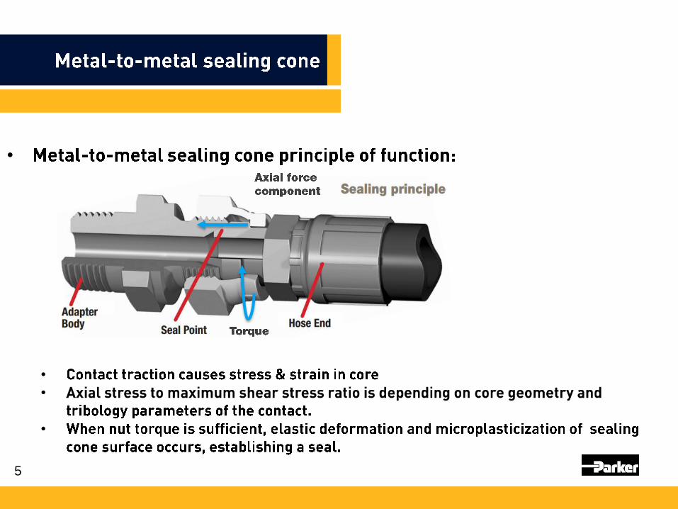
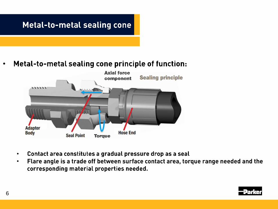
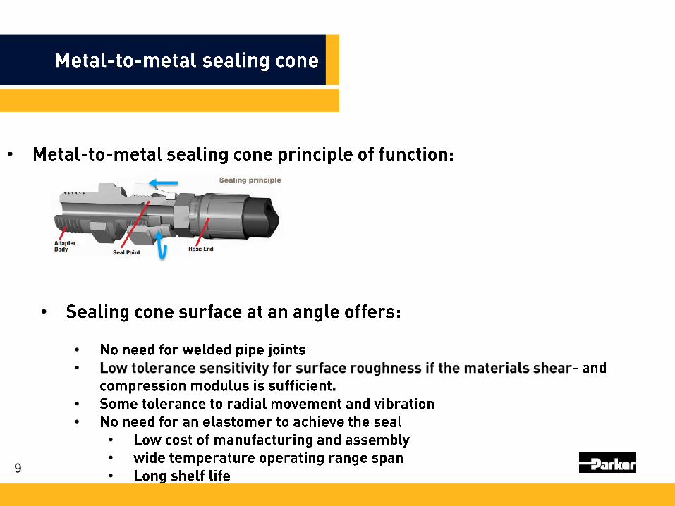
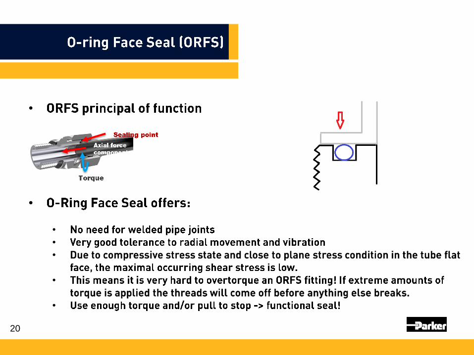
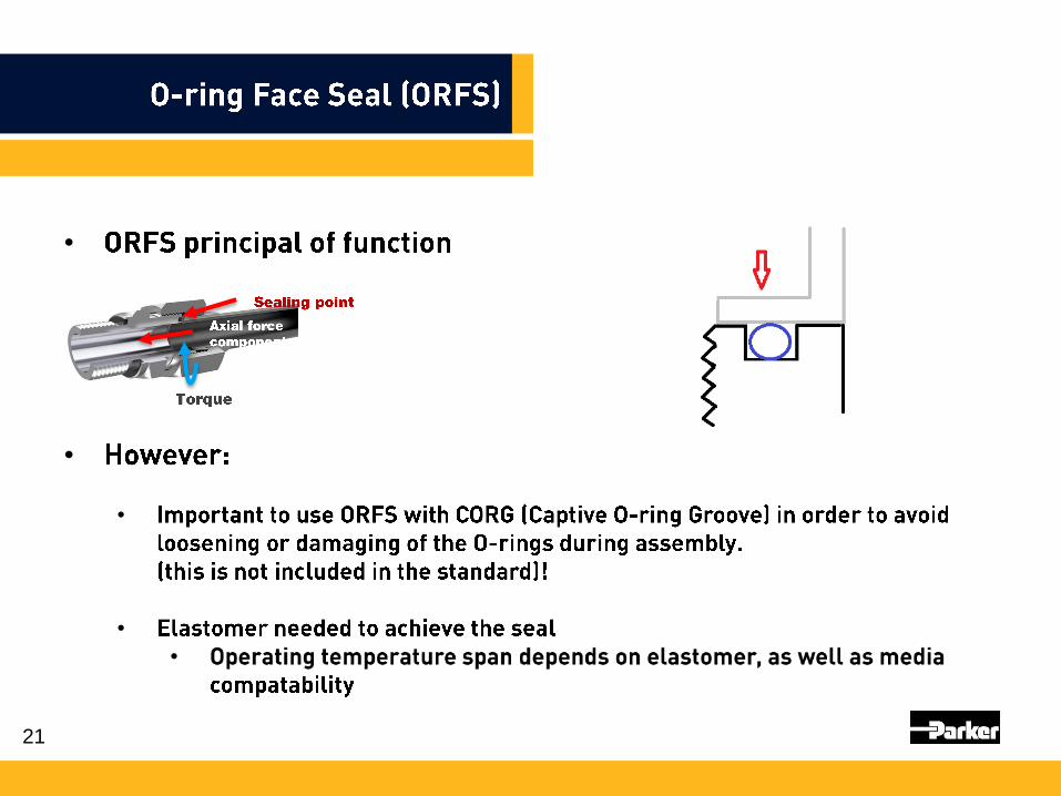
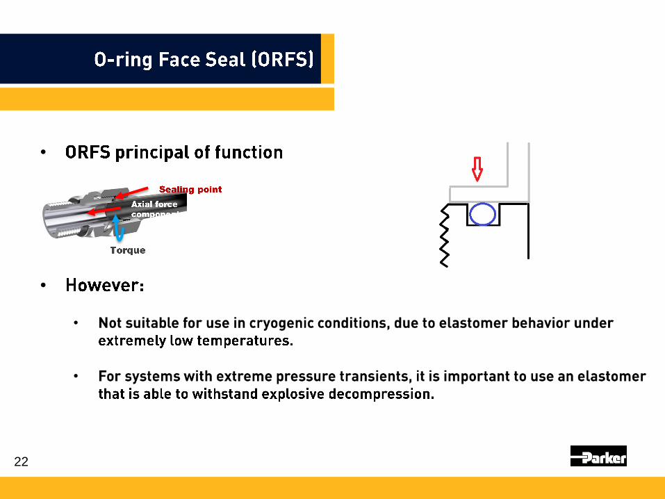
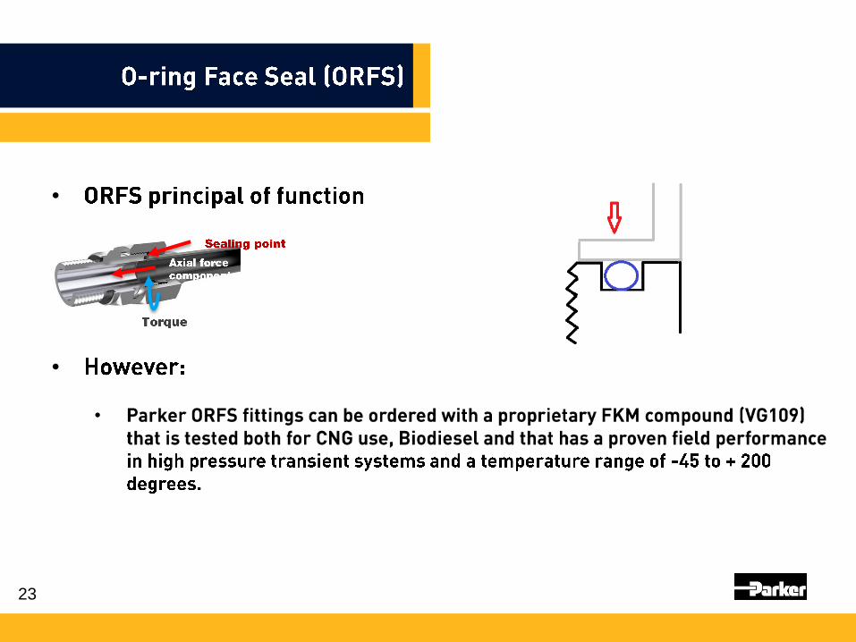
2 Sealing concepts for rigid and flexible fluid systems
O-Ring Face Seal
Vs.
45 degree conical face
2
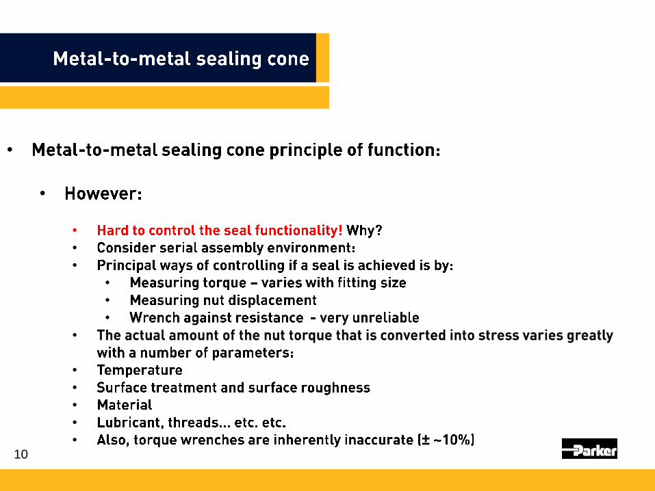
•
••
•
•
•
•
•
•
•
•
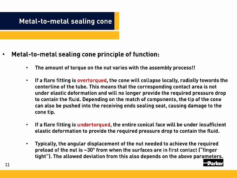
3
•
•
•
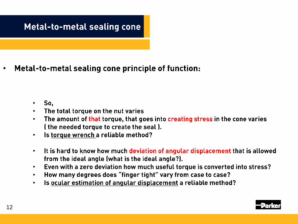
4
•
•
•
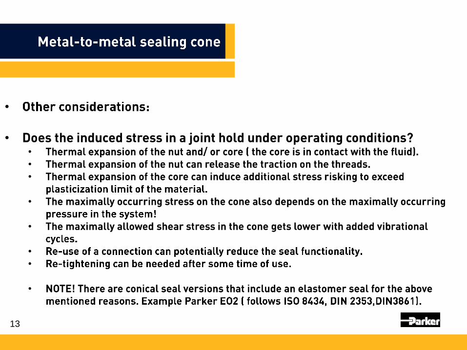
5
•
•
•
•
6
•
•
•
7
•
•
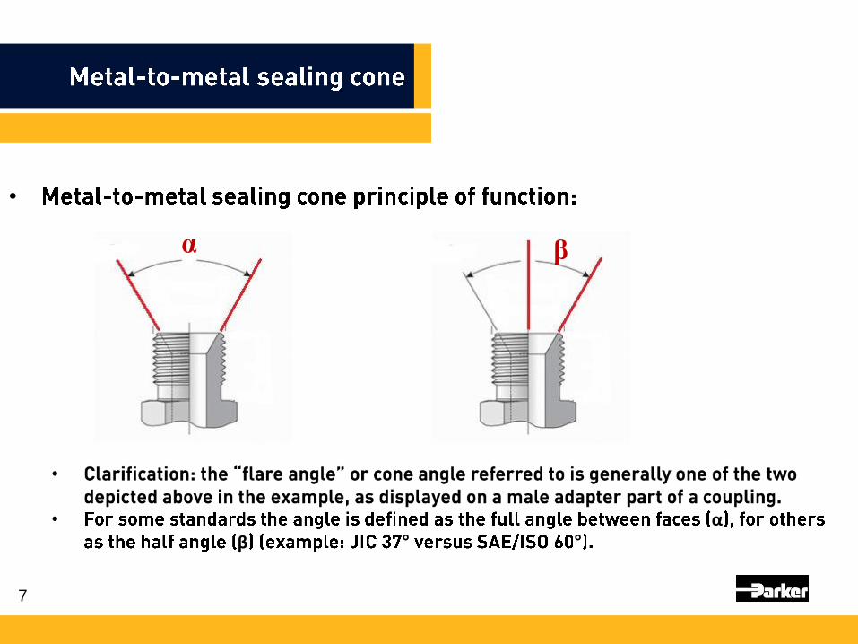
• αβ ° °
α β
8
•
•
•
•
•
9
•
•
•
•
•
•
•
•
•
10
•
•
•
•
•
•
•
•
•
•
•
•
•
• ±
11
•
•
•
•
•
°
12
•
•
•
•
•
•
•
•
•
13
•
••
•
•
•
•
•
•
•
14
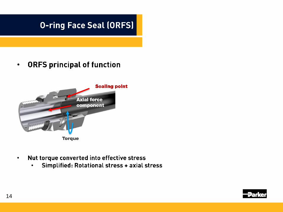
•
•
•

15
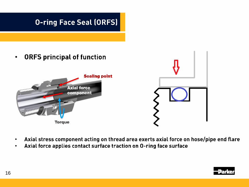
•
•
•
16
•
•
•
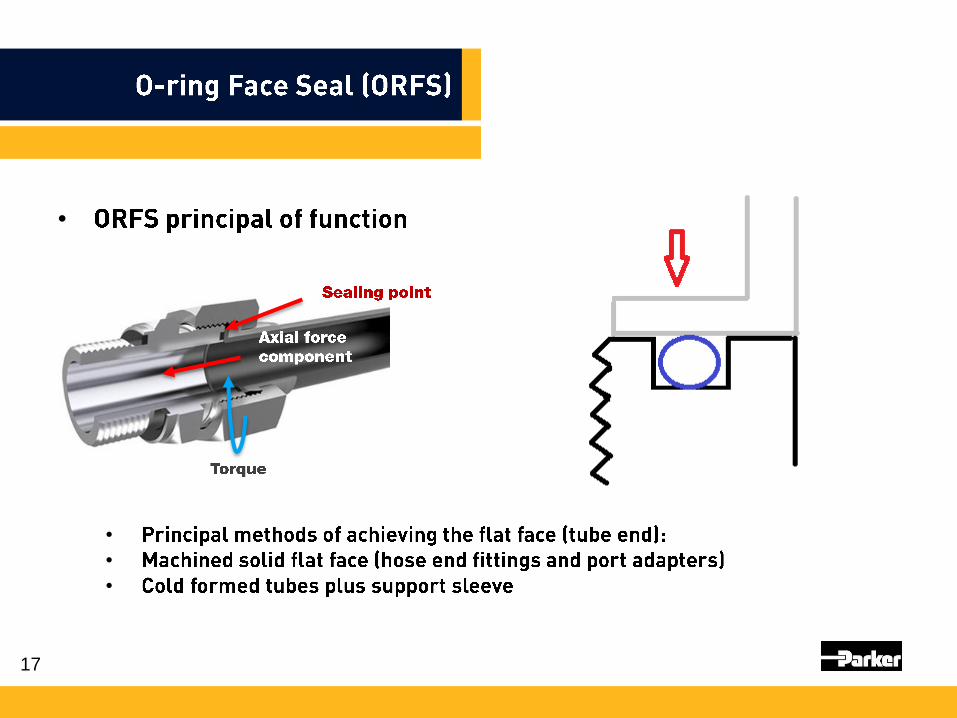
17
•
•
•
•
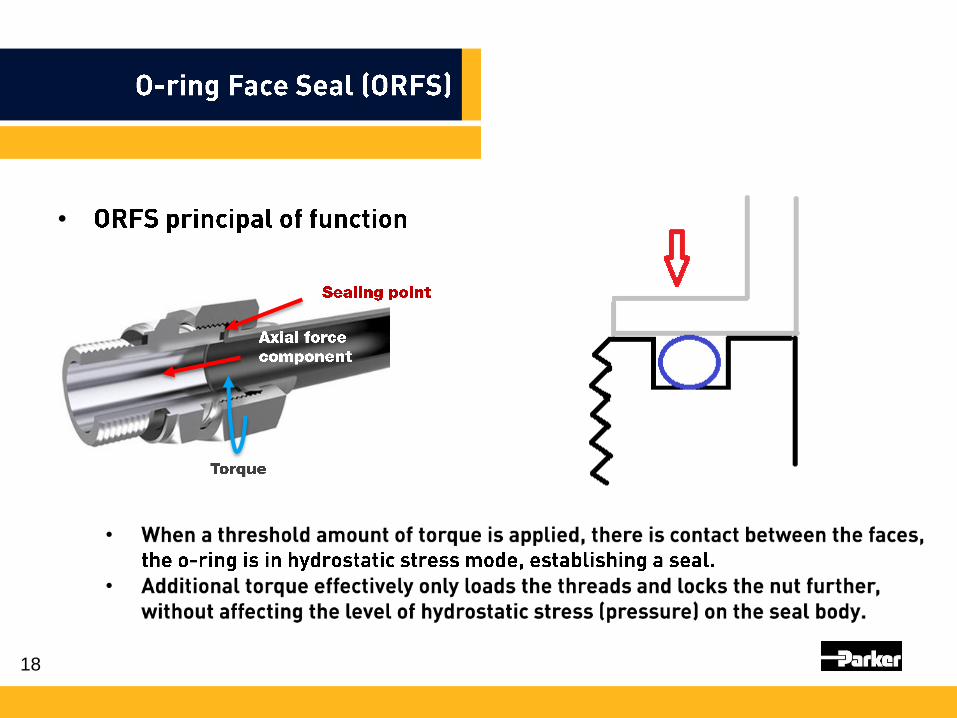
18
•
•
•

19
•
•
•
•
•
•
•
20
•
•
•
•
•
•
•
21
•
•
•
•
•
22
•
•
•
•
23
•
•
•
24
•
••
•
•
•
•
•
•
25
•
•
•
•
•
26
•
•
•
•
27
•
•
•
28
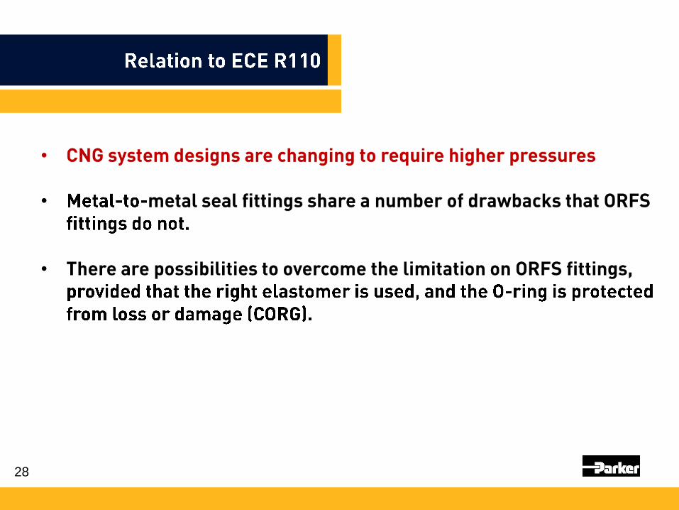
•
•
•
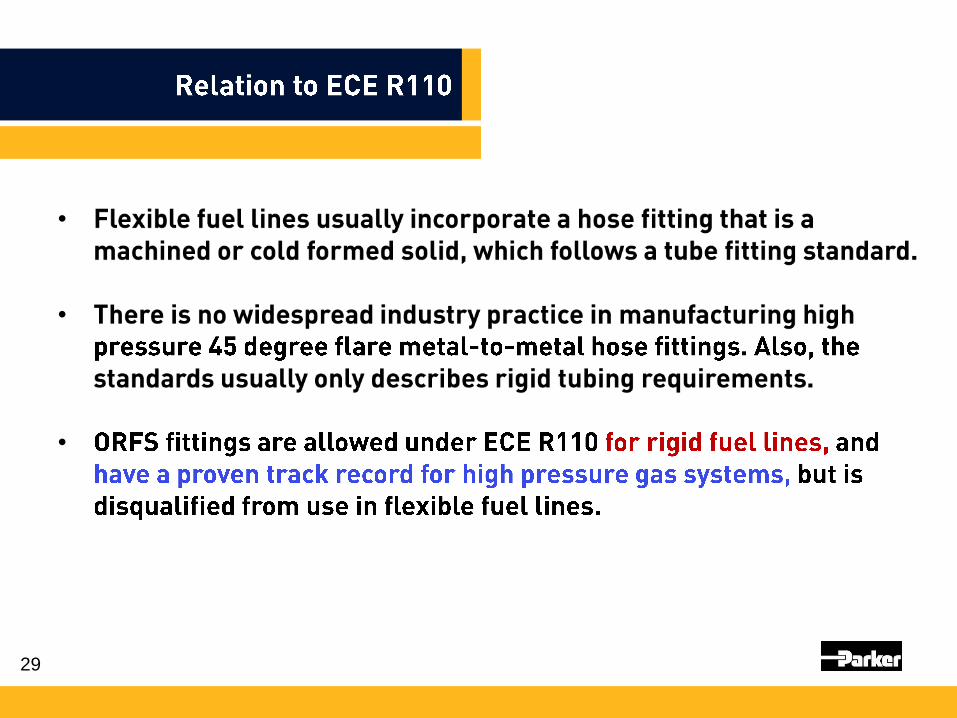
29
•
•
•
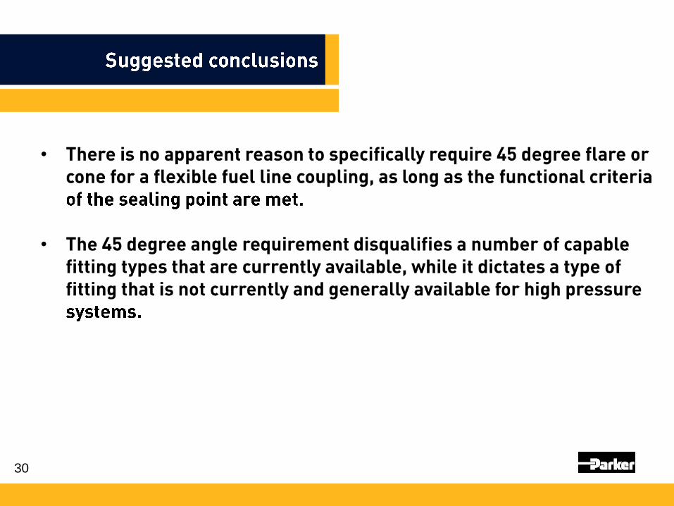
30
•
•
31
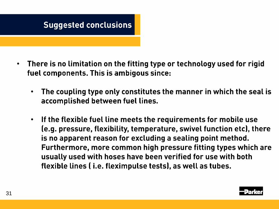
•
•
•
32
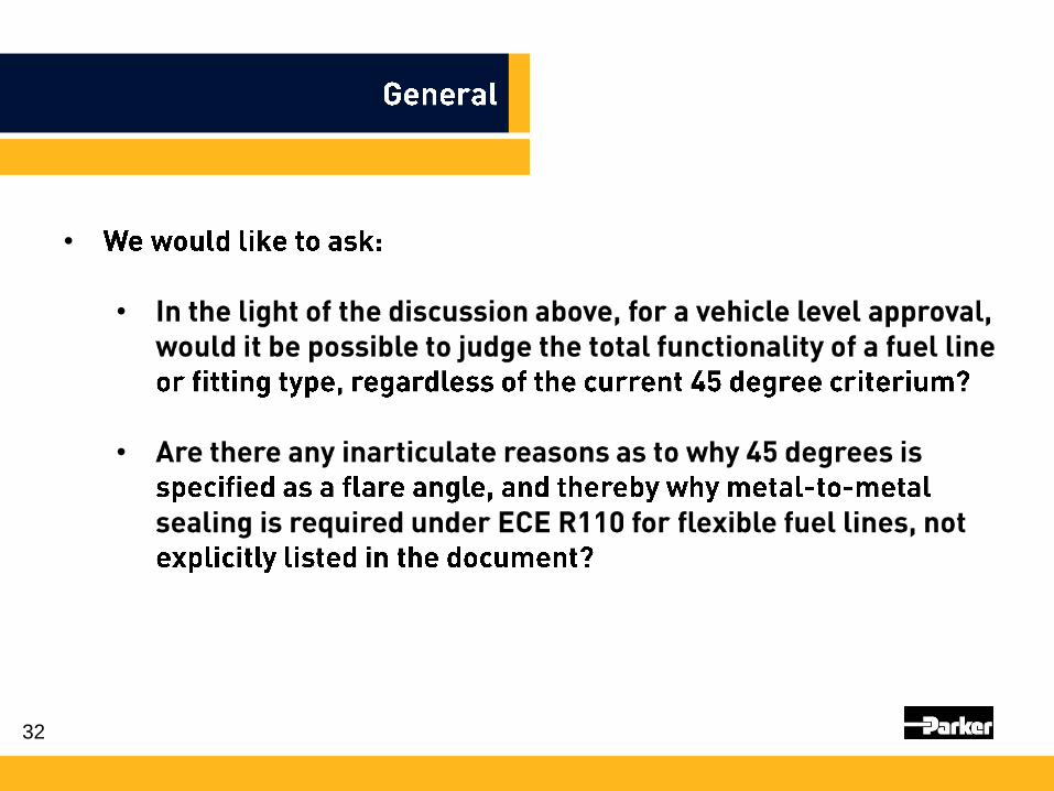
•
•
•
Errors in current regulation 110
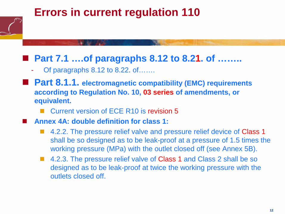
Part 7.1 ….of paragraphs 8.12 to 8.21. of …….. - Of paragraphs 8.12 to 8.22. of…….
Part 8.1.1. electromagnetic compatibility (EMC) requirements according to Regulation No. 10, 03 series of amendments, or equivalent. Current version of ECE R10 is revision 5
Annex 4A: double definition for class 1: 4.2.2. The pressure relief valve and pressure relief device of Class 1
shall be so designed as to be leak-proof at a pressure of 1.5 times the working pressure (MPa) with the outlet closed off (see Annex 5B).
4.2.3. The pressure relief valve of Class 1 and Class 2 shall be so designed as to be leak-proof at twice the working pressure with the outlets closed off.
12
Errors in current regulation 110
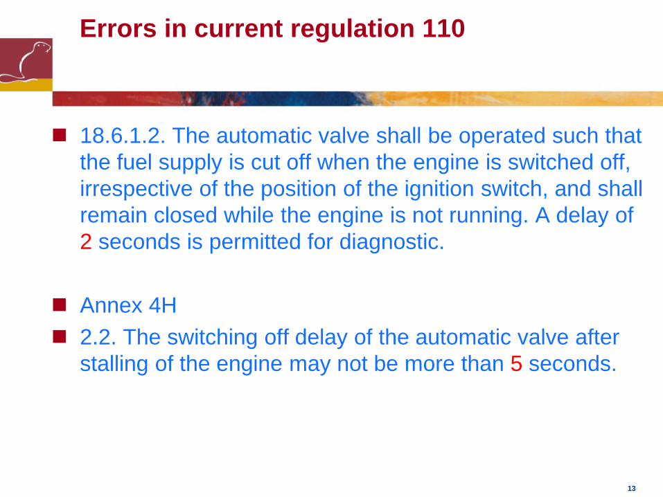
18.6.1.2. The automatic valve shall be operated such that the fuel supply is cut off when the engine is switched off, irrespective of the position of the ignition switch, and shall remain closed while the engine is not running. A delay of 2 seconds is permitted for diagnostic.
Annex 4H 2.2. The switching off delay of the automatic valve after
stalling of the engine may not be more than 5 seconds.
13

Thank you for your attention!
Questions?
14