64
ADAPT MAT RC Tutorial (SI units with European Code EC2) Update: April 2010 Copyright © ADAPT Corporation all rights reserved
ADAPT MAT RC Tutorial (SI units with European Code EC2)
Update: April 2010 Copyright © ADAPT Corporation all rights reserved

ADAPT MAT RC Tutorial (SI units with European Code EC2) I
MAT_RC_SI_EC_Spencer.doc
TABLE OF CONTENTS
1 Overview ........................................................................................................................ 1 2 Introduction .................................................................................................................... 2 3 Design Scope and criteria .............................................................................................. 3
3.1 Structural Layout ................................................................................................... 3 3.2 Material Properties ................................................................................................. 4
3.2.1 Concrete: ........................................................................................................ 4 3.2.2 Non-prestressed Reinforcement: .................................................................... 4 3.2.3 Soil: ................................................................................................................ 4
3.3 Applicable Codes ................................................................................................... 4 3.4 Structural Documents ............................................................................................. 4 3.5 Design Loads ......................................................................................................... 4
3.5.1 Dead Load ...................................................................................................... 4 3.5.2 Live Load ....................................................................................................... 5
3.6 Load Combinations and Stresses ........................................................................... 5 3.6.1 Strength Load Combinations ......................................................................... 5 3.6.2 Serviceability Load combinations .................................................................. 5
3.7 Deflections ............................................................................................................. 5 3.8 Cover ...................................................................................................................... 7 3.9 Soil properties ........................................................................................................ 7
3.9.1 Equivalent Spring Constant ........................................................................... 7 3.9.2 Soil Pressure................................................................................................... 7 3.9.3 Displacement at Interface of Soil Layers ....................................................... 8 3.9.4 Numerical Example ....................................................................................... 8
3.9.4.1 Given: ......................................................................................................... 8 3.9.4.2 Required: .................................................................................................... 8 3.9.4.3 Solution: ..................................................................................................... 8
4 Overview of ADAPT-Builder Platform ....................................................................... 10 4.1 ADAPT Builder Express (EX)® ......................................................................... 10 4.2 ADAPT Builder Initial Screen ............................................................................. 10 4.3 ADAPT-Modeler Main Screen ............................................................................ 12
4.3.1 Mouse Function and Operation .................................................................... 13 4.3.2 Transform to Structural Components Toolbar ............................................. 13 4.3.3 Selection Toolbar ......................................................................................... 14 4.3.4 Camera and Viewports Toolbar ................................................................... 17 4.3.5 Settings Toolbar ........................................................................................... 18 4.3.6 Snap Toolbar ................................................................................................ 18 4.3.7 Model/Design Strips Toolbar ....................................................................... 19 4.3.8 Modeling Toolbar ........................................................................................ 20 4.3.9 Modeling Toolbar ........................................................................................ 20 4.3.10 Support Line/Results Scale Toolbar ............................................................ 22 4.3.11 Reinforcement Toolbar ................................................................................ 23 4.3.12 Cursor Function and Operation .................................................................... 23
5 Generation of 3D Structural Model through DWG Import ......................................... 25 5.1 First Drawing Import ........................................................................................... 25 5.2 Transformation of Structural Component ............................................................ 26
6 Material, Soil Support Criteria and Loadings .............................................................. 30 6.1 Set and Assign Material Properties ...................................................................... 30
6.1.1 Set and Assign Multiple Concrete Material ................................................. 30
Table of Contents (II)
MAT_RC_SI_EC_Spencer.doc
6.1.2 Set and Assign Mild Steel Material (Rebar) ................................................ 32 6.2 Assign Soil Support ............................................................................................. 32 6.3 Set Criteria ........................................................................................................... 34 6.4 Input and Assign Loadings .................................................................................. 34
6.4.1 Patch Load Generation ................................................................................. 34 6.4.2 Line Load Generation .................................................................................. 35 6.4.3 Point Load Generation ................................................................................. 35 6.4.4 Load Combinations ...................................................................................... 36
7 Finite Element Meshing, Analysis and View Results .................................................. 38 7.1 Finite Element Meshing ....................................................................................... 38 7.2 Analyze Structure................................................................................................. 39 7.3 View Results ........................................................................................................ 39
7.3.1 View Deflection ........................................................................................... 40 7.3.2 Review of Soil Pressure ............................................................................... 41 7.3.3 Generate Line Contour ................................................................................. 42
8 Generation of Support Lines and Use of Splitters ....................................................... 45 8.1 Generation of Support Lines ................................................................................ 45 8.2 Use of Splitters ..................................................................................................... 46
Table of Contents (III)
MAT_RC_SI_EC_Spencer.doc
TABLE OF FIGURES FIGURE 3-1 Typical Reinforce Concrete Mat System ............................................................. 3 FIGURE 3-2 General Structural Plan (SI) ................................................................................. 3 FIGURE 3-3 Slab on Multi Layer Soil Foundation ................................................................... 7 FIGURE 4-1 ADAPT Builder Express Workflow .................................................................. 10 FIGURE 4-2 ADAPT Builder Initial Screen ........................................................................... 11 FIGURE 4-3 ADAPT Modeler Main Screen in MAT Mode .................................................. 12 FIGURE 4-4 Right-Click Options Of The Mouse ................................................................... 13 FIGURE 4-5 Transform to Structural Component Toolbar ..................................................... 13 FIGURE 4-6 Selection Toolbar ............................................................................................... 14 FIGURE 4-7 Select Layers Dialog Window ........................................................................... 15 FIGURE 4-8 Select by Type Dialog ........................................................................................ 16 FIGURE 4-9 Camera and Viewports Toolbar ......................................................................... 17 FIGURE 4-10 Setting Toolbar ................................................................................................. 18 FIGURE 4-11 Snap Toolbar .................................................................................................... 18 FIGURE 4-12 Model/Design Strips Toolbar ........................................................................... 19 FIGURE 4-13 Modeling Toolbar............................................................................................. 20 FIGURE 4-14 Support Line/Results Scale Toolbar ................................................................. 22 FIGURE 4-15 Reinforcement Toolbar .................................................................................... 23 FIGURE 5-1 Project Calibration Dialog.................................................................................. 25 FIGURE 5-2 Start and End Points of Calibration Line ........................................................... 26 FIGURE 5-3 Transform to Structural Component Toolbar ..................................................... 26 FIGURE 5-4 Layers Dialog Box ............................................................................................. 27 FIGURE 5-5 Top-Front-Right View with Transformed Column and Column Dialog ........... 27 FIGURE 5-6 View Toolbar and View Menu (partial) ............................................................. 28 FIGURE 5-7 Select/ Set View Items Dialog Box .................................................................... 29 FIGURE 6-1 Concrete Material Dialog Box ........................................................................... 30 FIGURE 6-2 Modify Item Properties dialog box .................................................................... 31 FIGURE 6-3 Slab Region Dialog Box..................................................................................... 32 FIGURE 6-4 Soil Support Menu Item ..................................................................................... 32 FIGURE 6-5 Soil Support inscribing the Mat Foundation ...................................................... 33 FIGURE 6-6 Soil Support Property Box ................................................................................. 33 FIGURE 6-7 Design Code Tab inside Criteria Dialog Box .................................................... 34 FIGURE 6-8 Automatic Patch Load Wizard ........................................................................... 35 FIGURE 6-9 Automatic Line Load Wizard ............................................................................. 35 FIGURE 6-10 Point Load Dialog Box (General and Loads Tabs) .......................................... 36 FIGURE 6-11 Load Combination Dialog Box ........................................................................ 37 FIGURE 7-1 Automatic Mesh Generation Dialog .................................................................. 38 FIGURE 7-2 Finite Element Mesh .......................................................................................... 39 FIGURE 7-3 FEM Menu ......................................................................................................... 40

Table of Contents (IV)
MAT_RC_SI_EC_Spencer.doc
BLANK PAGE
ADAPT-MAT RC Tutorial (SI units with European Code EC2) 1
MAT_RC_SI_EC_Spencer.doc 1. Overview
1 OVERVIEW
This workshop/tutorial package (herein referred to as “tutorial”) is tailored to the needs of design engineers who are seeking to become familiar with the latest developments in design of reinforced concrete mat or raft slab systems (foundation slab consisting of extended layers of concrete and usual resting on soft ground). The tutorial covers, in detail, the process of designing a reinforced concrete mat foundation using the ADAPT-Builder suite of software with focus on ADAPT-Modeler & ADAPT-MAT. Long regarded as a difficult engineering challenge, designing concrete floor systems is greatly simplified with ADAPT-Builder, which provides significant efficiencies throughout the design process. Associated CAD files, data and documentation needed to continue with this tutorial is also available upon request. This tutorial is broken into several sessions, which would likely to take four hours in total. This tutorial uses the following programs of the ADAPT-Builder Design Suite:
ADAPT-Modeler® 2009 or later ADAPT-MAT® 2009 or later ADAPT-Dynamic Rebar Design™ Extension Module
Contact ADAPT at [email protected] if you need additional information.
ADAPT-MAT RC Tutorial (SI Units with European Code EC2) 2
MAT_RC_SI_EC_Spencer.doc 2. Introduction
2 INTRODUCTION
The complete modelling, analysis, design and detailing of a reinforced concrete mat/raft slab system is outlined in this tutorial. It covers the procedure of transforming a 2D drawing file into a structural model necessary for the completion of FEM analysis and design. Loading the structure will incorporate several options built-in to the ADAPT-Modeler environment making this procedure more efficient. The tutorial will conclude with the output showing general modelling arrangements, structural calculation reports and the non-prestressed reinforcement layout. More advanced topics related to the modelling and design of mat systems will be covered throughout the tutorial with respect to ADAPT-MAT. The tutorial is broken down into a number of sessions, each intended to guide you through a specific aspect of design and offers topics that might generally be considered at the intermediate or advanced level. The material that follows is better suited for a user that has some basic familiarity with ADAPT-Builder, however much of the content is applicable to beginners as well. The raft/mat system selected for the tutorial was specifically developed, to demonstrate salient steps of reinforced concrete mat foundation design using the ADAPT-Builder environment. The overall dimensions are approximately 50 x 27 meter. The project data for this tutorial has been generated in SI units. The European Code (EC2) has been selected for this tutorial. However where the code is moot, provisions from TR 43, ACI and other building codes are referenced. The bulk of material presented in this tutorial applies to the majority of building codes included in the software, such as ACI, IS, Australian, Canadian and BS8110. Items such as allowable stresses, load combinations and associated factors will change depending on the code that is selected for design. IMPORTANT NOTE: In some Windows versions, the folders copied from a CD or the files downloaded from the BLOG will have “Read Only” attribute. To open and run the data you have copied in your computer, you must remove the “Read Only” attribute. If you do not remove the “Read Only” attribute, the tutorial programs will not function properly.
ADAPT-MAT RC Tutorial (SI units with European Code EC2) 3
MAT_RC_SI_EC_Spencer.doc 3. Design Scope and Criteria
3 DESIGN SCOPE AND CRITERIA
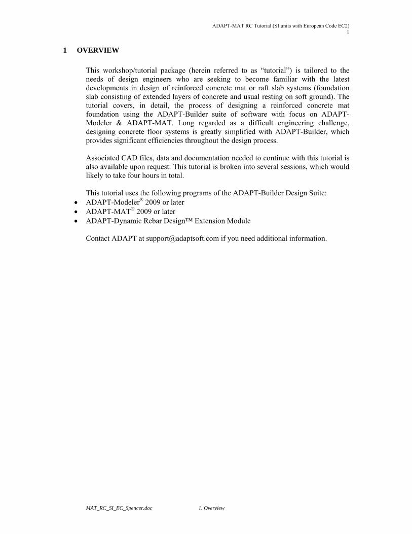
3.1 STRUCTURAL LAYOUT This outlines the criteria to be used for the structural design of the mat system (Fig. 3-1) selected for this tutorial.
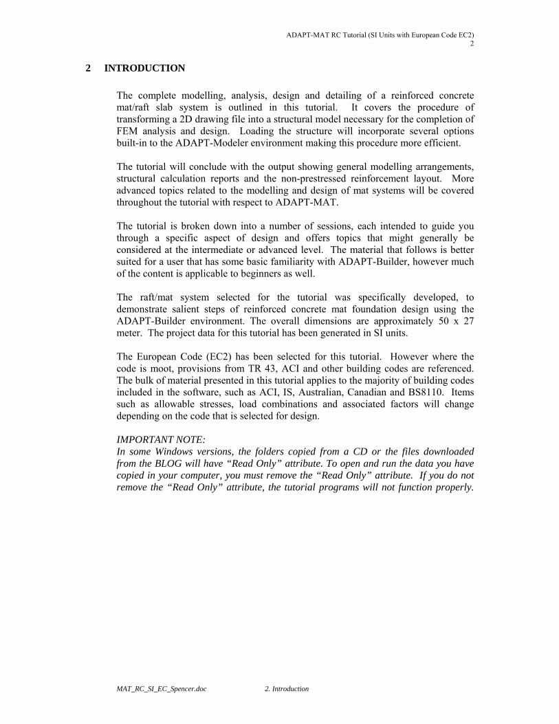
FIGURE 3-1 Typical Reinforce Concrete Mat System The concrete outline and the general structural plan with key dimensions are shown below:
FIGURE 3-2 General Structural Plan (SI)
ADAPT-MAT RC Tutorial (SI Units with European Code EC2) 4
MAT_RC_SI_EC_Spencer.doc 3. Design Scope and Criteria
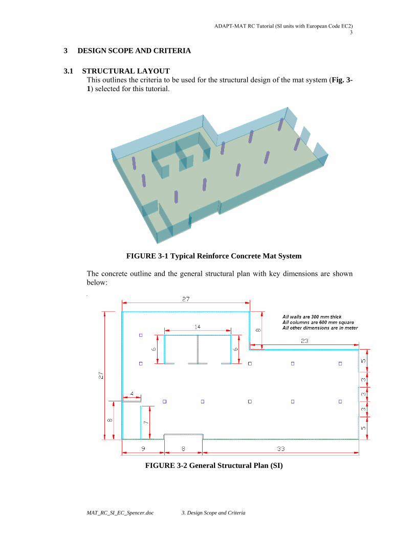
3.2 MATERIAL PROPERTIES 3.2.1 Concrete:
Weight = 2400 kg/m3 Cylinder Strength (f’c) at 28 days = 30 MPa (slab);
40 MPa (column & wall) Creep Coefficient = 2
3.2.2 Non-prestressed Reinforcement:
Yield Strength = 460 MPa Modulus of Elasticity = 200,000 MPa
3.2.3 Soil:
Allowable Long Term Pressure = 100 kPa = 0.1 MPa
3.3 APPLICABLE CODES
The design is based on EC 2 (ENV 1992-1-1). Where the code is moot, the recommendations of ACI 318, CEB/FIP Model Code, TR 43 and International codes will be used.
3.4 STRUCTURAL DOCUMENTS
The final design should include following
Structural Calculation General Arrangement Drawings Loading Plans Design Section Report Rebar required and provided at all locations Design Section Capacity
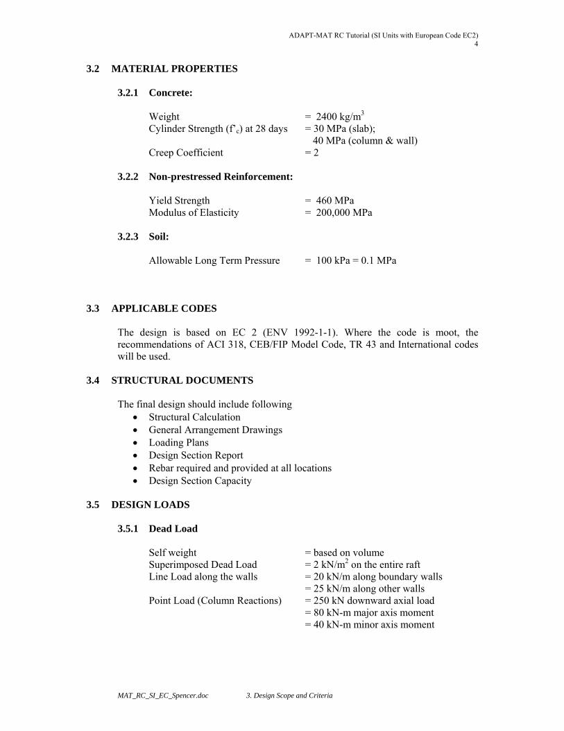
3.5 DESIGN LOADS
3.5.1 Dead Load
Self weight = based on volume
Superimposed Dead Load = 2 kN/m2 on the entire raft Line Load along the walls = 20 kN/m along boundary walls = 25 kN/m along other walls Point Load (Column Reactions) = 250 kN downward axial load = 80 kN-m major axis moment = 40 kN-m minor axis moment
ADAPT-MAT RC Tutorial (SI units with European Code EC2) 5
MAT_RC_SI_EC_Spencer.doc 3. Design Scope and Criteria
3.5.2 Live Load
Uniformly Distributed = 10 kN/m2
NOTE: Lateral loads (i.e. wind or seismic) have been considered for this tutorial. Please refer to the ADAPT-IC tutorials for additional information on the most efficient method for introducing such loads into an ADAPT-MAT model.
3.6 LOAD COMBINATIONS AND STRESSES
The parts and factors of the program’s automatically generated load cases and load combinations are listed below. Except for the initial (transfer) condition, which is not explicitly defined in the code, the remainder of the combinations follows EC2 stipulations. 3.6.1 Strength Load Combinations The strength requirement for each member is established using the following factored load combination:
U = 1.35 x Selfweight + 1.35 x Dead load + 1.50 x Live load 3.6.2 Serviceability Load combinations Load Combinations for Serviceability Check: Quasi-permanent in-service load combination (stress check)
U = 1.00 x Selfweight + 1.00 x Dead load + 0.30 x Live load Frequent in-service load combination (stress check)
U = 1.00 x Selfweight + 1.00 x Dead load + 0.50 x Live load 3.7 DEFLECTIONS
Having maintained the hypothetical tensile stresses within the limits stated in the preceding, the deflections will be calculated for both uncracked (gross moment of inertia) and cracked (effective moment of inertia). Long-term deflections are estimated using a creep coefficient of 2.
For the mat foundation the maximum deflections are maintained below the following values with the understanding that the structure is not attached to nonstructural elements likely to be damaged by large deflections of the slab: Maximum allowable total long term deflection = L/250 Maximum allowable live load deflection = L/360 Where, L = length of clear span. Hence, the load combination for long-term deflection due to creep and the instantaneous action of live load:

ADAPT-MAT RC Tutorial (SI Units with European Code EC2) 6
MAT_RC_SI_EC_Spencer.doc 3. Design Scope and Criteria
U = 3.00 X Dead load + 1.00 x Live load Load combination for checking deflection under live load:
U = 1.00 LL
ADAPT-MAT RC Tutorial (SI units with European Code EC2) 7
MAT_RC_SI_EC_Spencer.doc 3. Design Scope and Criteria
3.8 COVER Mild Reinforcement clear covers are given below: Cover to top bars = 35 mm Cover to bottom bars = 40 mm
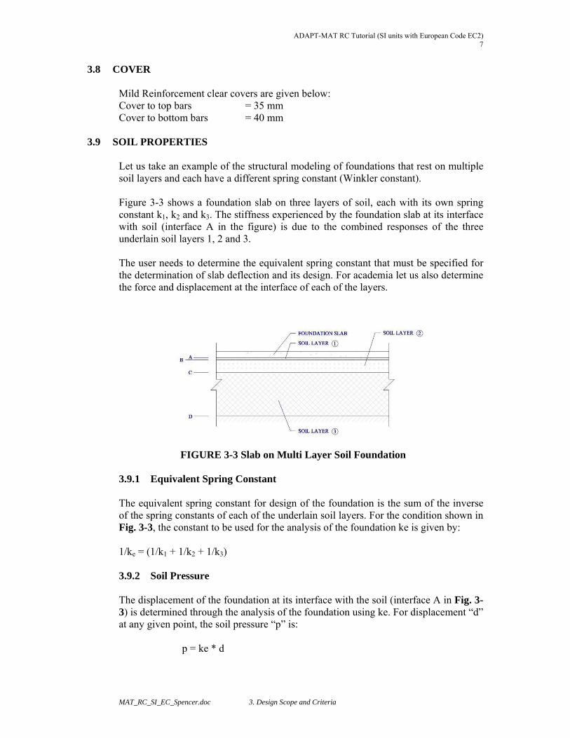
3.9 SOIL PROPERTIES Let us take an example of the structural modeling of foundations that rest on multiple soil layers and each have a different spring constant (Winkler constant). Figure 3-3 shows a foundation slab on three layers of soil, each with its own spring constant k1, k2 and k3. The stiffness experienced by the foundation slab at its interface with soil (interface A in the figure) is due to the combined responses of the three underlain soil layers 1, 2 and 3. The user needs to determine the equivalent spring constant that must be specified for the determination of slab deflection and its design. For academia let us also determine the force and displacement at the interface of each of the layers.
FIGURE 3-3 Slab on Multi Layer Soil Foundation 3.9.1 Equivalent Spring Constant The equivalent spring constant for design of the foundation is the sum of the inverse of the spring constants of each of the underlain soil layers. For the condition shown in Fig. 3-3, the constant to be used for the analysis of the foundation ke is given by: 1/ke = (1/k1 + 1/k2 + 1/k3) 3.9.2 Soil Pressure The displacement of the foundation at its interface with the soil (interface A in Fig. 3-3) is determined through the analysis of the foundation using ke. For displacement “d” at any given point, the soil pressure “p” is:
p = ke * d
ADAPT-MAT RC Tutorial (SI Units with European Code EC2) 8
MAT_RC_SI_EC_Spencer.doc 3. Design Scope and Criteria
The soil pressure “p” remains the same for the underlain layers. It will be the same for layers A, B and C shown in the figure. 3.9.3 Displacement at Interface of Soil Layers At interface A, the vertical displacement is equal to the value determined from the analysis of the foundation slab, namely “d.” The reduction (r) in thickness of layer 1 is: r1 = p/k1 Hence, the vertical displacement of interface B will be: dB = d – rA Using a similar procedure, the displacement of the interface between other layers can be determined. 3.9.4 Numerical Example
3.9.4.1 Given:
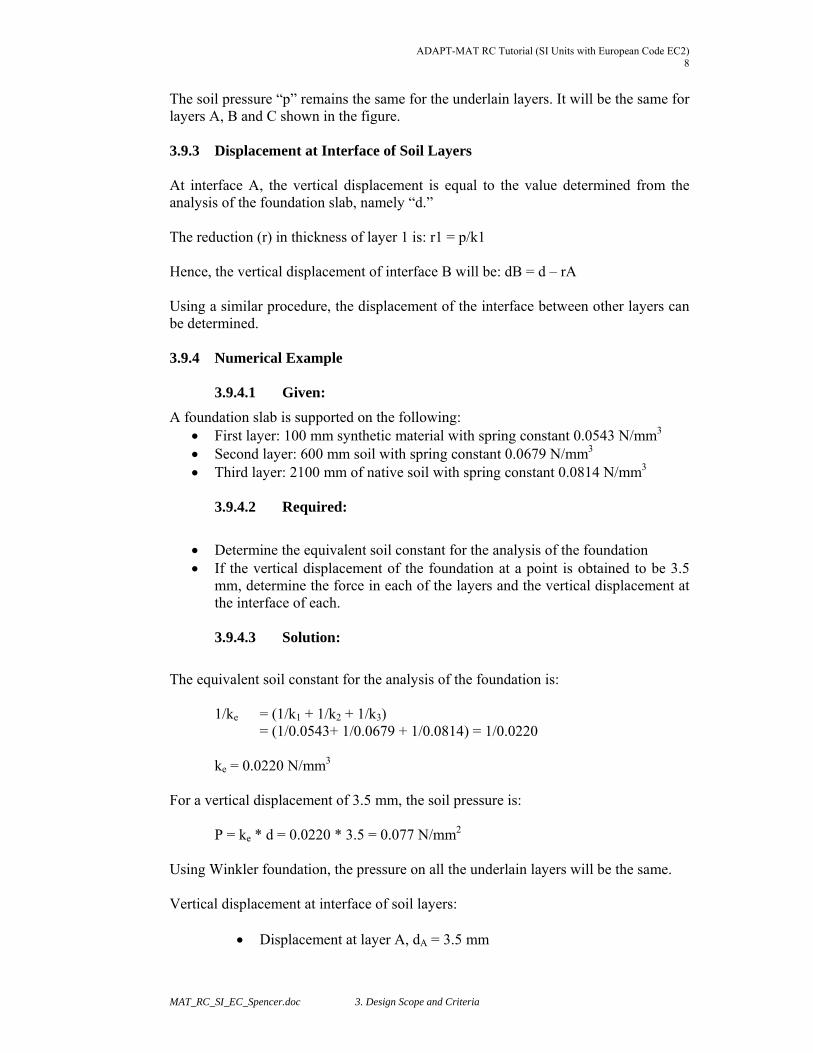
A foundation slab is supported on the following: First layer: 100 mm synthetic material with spring constant 0.0543 N/mm3 Second layer: 600 mm soil with spring constant 0.0679 N/mm3 Third layer: 2100 mm of native soil with spring constant 0.0814 N/mm3
3.9.4.2 Required:
Determine the equivalent soil constant for the analysis of the foundation If the vertical displacement of the foundation at a point is obtained to be 3.5
mm, determine the force in each of the layers and the vertical displacement at the interface of each.
3.9.4.3 Solution:
The equivalent soil constant for the analysis of the foundation is:
1/ke = (1/k1 + 1/k2 + 1/k3)
= (1/0.0543+ 1/0.0679 + 1/0.0814) = 1/0.0220 ke = 0.0220 N/mm3
For a vertical displacement of 3.5 mm, the soil pressure is:
P = ke * d = 0.0220 * 3.5 = 0.077 N/mm2 Using Winkler foundation, the pressure on all the underlain layers will be the same. Vertical displacement at interface of soil layers:
Displacement at layer A, dA = 3.5 mm

ADAPT-MAT RC Tutorial (SI units with European Code EC2) 9
MAT_RC_SI_EC_Spencer.doc 3. Design Scope and Criteria
Compression in thickness of first layer:
r1 = p/k1 = 0.077/0.0543 = 1.42 mm
Displacement at layer B, dB = dA – r1 = 3.5 – 1.42 = 2.08 mm Compression in thickness of second layer:
r2 = p/k2 = 0.077/0.0679 = 1.13 mm
Displacement at layer C, dC = dB – r2 = 2.08 – 1.13 = 0.95 mm Compression in thickness of third layer:
r3 = p/k3 = 0.077/0.0814 = 0.95 mm Displacement at layer D, dD = dC – r3 = 0.95 – 0.95 = 0.00 mm
No displacement value at interface D agrees with the assumptions of the example.
ADAPT-MAT RC Tutorial (SI Units with European Code EC2) 10
MAT_RC_SI_EC_Spencer.doc 4. Overview of ADAPT-Builder Platform
4 OVERVIEW OF ADAPT-BUILDER PLATFORM
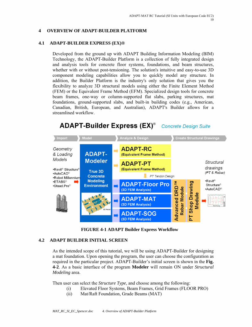
4.1 ADAPT-BUILDER EXPRESS (EX)® Developed from the ground up with ADAPT Building Information Modeling (BIM) Technology, the ADAPT-Builder Platform is a collection of fully integrated design and analysis tools for concrete floor systems, foundations, and beam structures, whether with or without post-tensioning. The solution's intuitive and easy-to-use 3D component modeling capabilities allow you to quickly model any structure. In addition, the Builder Platform is the industry's only solution that gives you the flexibility to analyze 3D structural models using either the Finite Element Method (FEM) or the Equivalent Frame Method (EFM). Specialized design tools for concrete beam frames, one-way or column-supported flat slabs, parking structures, mat foundations, ground-supported slabs, and built-in building codes (e.g., American, Canadian, British, European, and Australian), ADAPT's Builder allows for a streamlined workflow.
FIGURE 4-1 ADAPT Builder Express Workflow
4.2 ADAPT BUILDER INITIAL SCREEN As the intended scope of this tutorial, we will be using ADAPT-Builder for designing a mat foundation. Upon opening the program, the user can choose the configuration as required in the particular project. ADAPT-Builder’s initial screen is shown in the Fig. 4-2. As a basic interface of the program Modeler will remain ON under Structural Modeling area. Then user can select the Structure Type, and choose among the following:
(i) Elevated Floor Systems, Beam Frames, Grid Frames (FLOOR PRO) (ii) Mat/Raft Foundation, Grade Beams (MAT)
ADAPT-MAT RC Tutorial (SI units with European Code EC2) 11
MAT_RC_SI_EC_Spencer.doc5. Generation of 3D Structural Model through DWG Import
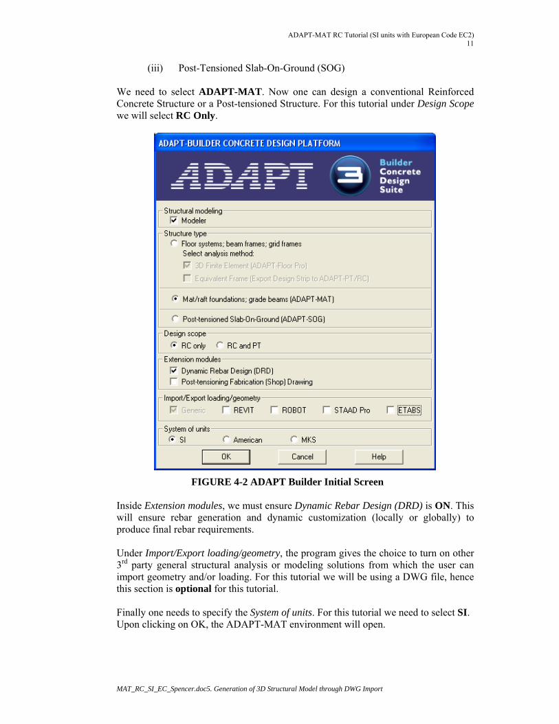
(iii) Post-Tensioned Slab-On-Ground (SOG) We need to select ADAPT-MAT. Now one can design a conventional Reinforced Concrete Structure or a Post-tensioned Structure. For this tutorial under Design Scope we will select RC Only.
FIGURE 4-2 ADAPT Builder Initial Screen Inside Extension modules, we must ensure Dynamic Rebar Design (DRD) is ON. This will ensure rebar generation and dynamic customization (locally or globally) to produce final rebar requirements. Under Import/Export loading/geometry, the program gives the choice to turn on other 3rd party general structural analysis or modeling solutions from which the user can import geometry and/or loading. For this tutorial we will be using a DWG file, hence this section is optional for this tutorial. Finally one needs to specify the System of units. For this tutorial we need to select SI. Upon clicking on OK, the ADAPT-MAT environment will open.
ADAPT-MAT RC Tutorial (SI Units with European Code EC2) 12
MAT_RC_SI_EC_Spencer.doc 4. Overview of ADAPT-Builder Platform
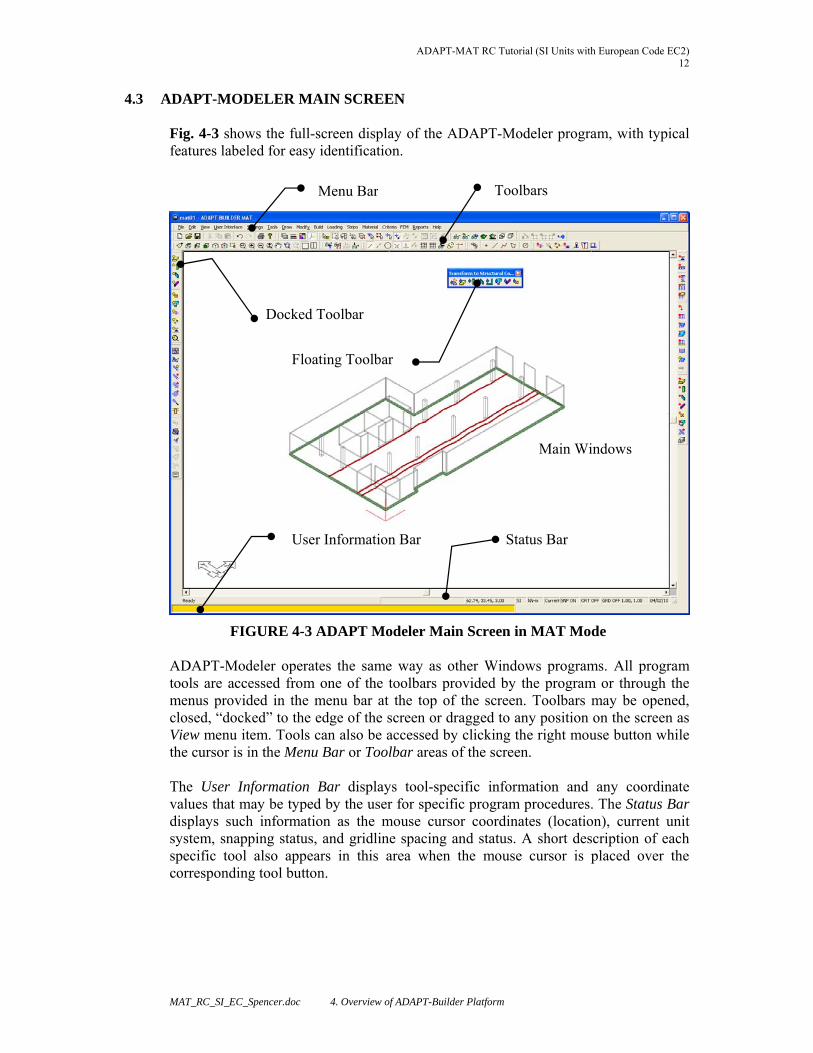
4.3 ADAPT-MODELER MAIN SCREEN Fig. 4-3 shows the full-screen display of the ADAPT-Modeler program, with typical features labeled for easy identification.
FIGURE 4-3 ADAPT Modeler Main Screen in MAT Mode ADAPT-Modeler operates the same way as other Windows programs. All program tools are accessed from one of the toolbars provided by the program or through the menus provided in the menu bar at the top of the screen. Toolbars may be opened, closed, “docked” to the edge of the screen or dragged to any position on the screen as View menu item. Tools can also be accessed by clicking the right mouse button while the cursor is in the Menu Bar or Toolbar areas of the screen. The User Information Bar displays tool-specific information and any coordinate values that may be typed by the user for specific program procedures. The Status Bar displays such information as the mouse cursor coordinates (location), current unit system, snapping status, and gridline spacing and status. A short description of each specific tool also appears in this area when the mouse cursor is placed over the corresponding tool button.
Toolbars
User Information Bar
Floating Toolbar
Status Bar
Docked Toolbar
Menu Bar
Main Windows
ADAPT-MAT RC Tutorial (SI units with European Code EC2) 13
MAT_RC_SI_EC_Spencer.doc5. Generation of 3D Structural Model through DWG Import
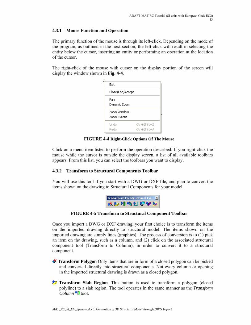
4.3.1 Mouse Function and Operation The primary function of the mouse is through its left-click. Depending on the mode of the program, as outlined in the next section, the left-click will result in selecting the entity below the cursor, inserting an entity or performing an operation at the location of the cursor. The right-click of the mouse with cursor on the display portion of the screen will display the window shown in Fig. 4-4.
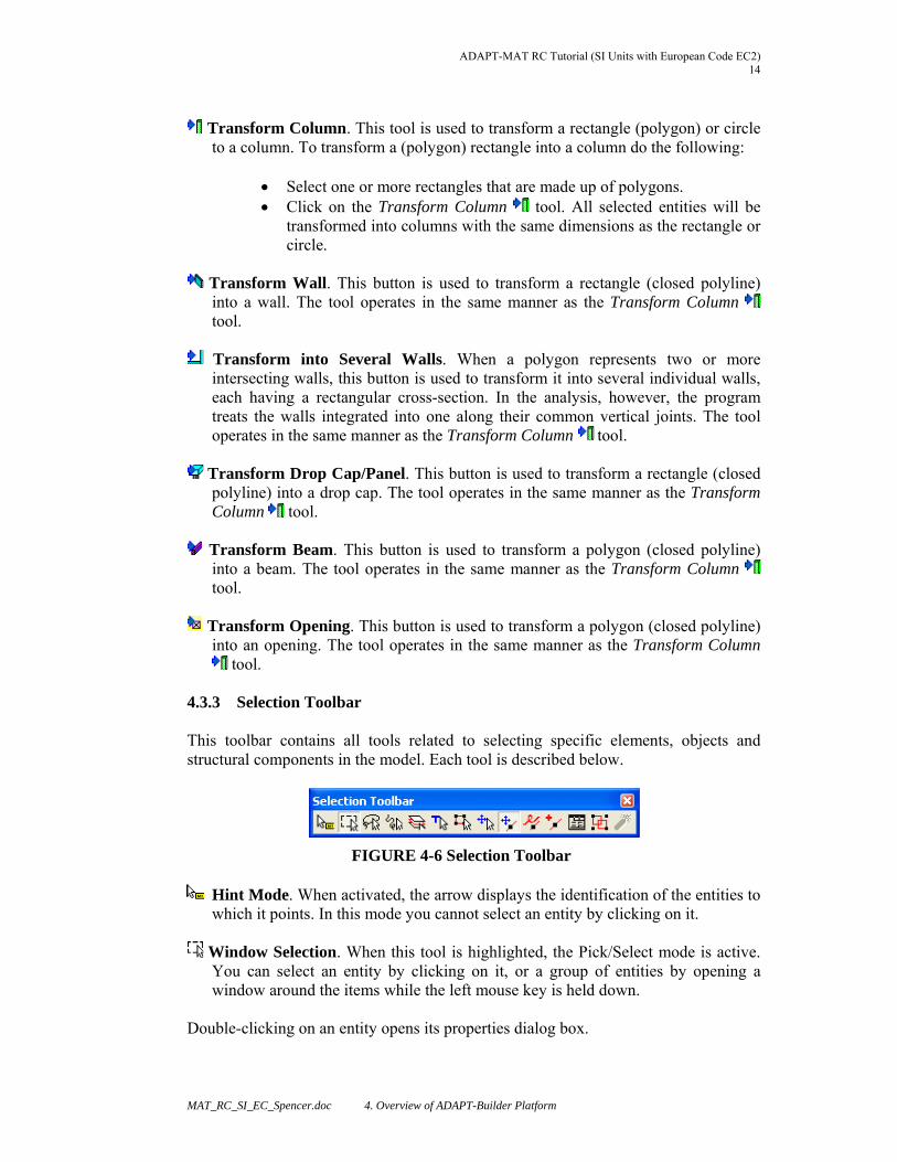
FIGURE 4-4 Right-Click Options Of The Mouse Click on a menu item listed to perform the operation described. If you right-click the mouse while the cursor is outside the display screen, a list of all available toolbars appears. From this list, you can select the toolbars you want to display. 4.3.2 Transform to Structural Components Toolbar You will use this tool if you start with a DWG or DXF file, and plan to convert the items shown on the drawing to Structural Components for your model.
FIGURE 4-5 Transform to Structural Component Toolbar Once you import a DWG or DXF drawing, your first choice is to transform the items on the imported drawing directly to structural model. The items shown on the imported drawing are simply lines (graphics). The process of conversion is to (1) pick an item on the drawing, such as a column, and (2) click on the associated structural component tool (Transform to Column), in order to convert it to a structural component.
Transform Polygon Only items that are in form of a closed polygon can be picked and converted directly into structural components. Not every column or opening in the imported structural drawing is drawn as a closed polygon.
Transform Slab Region. This button is used to transform a polygon (closed
polyline) to a slab region. The tool operates in the same manner as the Transform Column tool.
ADAPT-MAT RC Tutorial (SI Units with European Code EC2) 14
MAT_RC_SI_EC_Spencer.doc 4. Overview of ADAPT-Builder Platform
Transform Column. This tool is used to transform a rectangle (polygon) or circle
to a column. To transform a (polygon) rectangle into a column do the following:
Select one or more rectangles that are made up of polygons. Click on the Transform Column tool. All selected entities will be
transformed into columns with the same dimensions as the rectangle or circle.
Transform Wall. This button is used to transform a rectangle (closed polyline)
into a wall. The tool operates in the same manner as the Transform Column tool.
Transform into Several Walls. When a polygon represents two or more
intersecting walls, this button is used to transform it into several individual walls, each having a rectangular cross-section. In the analysis, however, the program treats the walls integrated into one along their common vertical joints. The tool operates in the same manner as the Transform Column tool.
Transform Drop Cap/Panel. This button is used to transform a rectangle (closed
polyline) into a drop cap. The tool operates in the same manner as the Transform Column tool.
Transform Beam. This button is used to transform a polygon (closed polyline)
into a beam. The tool operates in the same manner as the Transform Column tool.
Transform Opening. This button is used to transform a polygon (closed polyline)
into an opening. The tool operates in the same manner as the Transform Column tool.
4.3.3 Selection Toolbar This toolbar contains all tools related to selecting specific elements, objects and structural components in the model. Each tool is described below.
FIGURE 4-6 Selection Toolbar
Hint Mode. When activated, the arrow displays the identification of the entities to which it points. In this mode you cannot select an entity by clicking on it.
Window Selection. When this tool is highlighted, the Pick/Select mode is active.
You can select an entity by clicking on it, or a group of entities by opening a window around the items while the left mouse key is held down.
Double-clicking on an entity opens its properties dialog box.
ADAPT-MAT RC Tutorial (SI units with European Code EC2) 15
MAT_RC_SI_EC_Spencer.doc5. Generation of 3D Structural Model through DWG Import
Lasso Selection. This tool allows you to draw an arbitrary polygon around a series of entities. When the lasso is closed, all entities located within or along the lasso perimeter are selected. To use this tool, do the following:
Click on the Lasso Selection tool. Draw segments of the polygon around the entities to be selected. Press C to close the lasso. The entities inside the lasso are selected
automatically.
Path Selection. With this tool you can select entities by drawing a polyline through them. To use this tool, do the following:
Click on the Path Selection tool. Draw polyline through the entities to be selected. Press C to end the line. The entities through which the line passes will be
selected automatically.
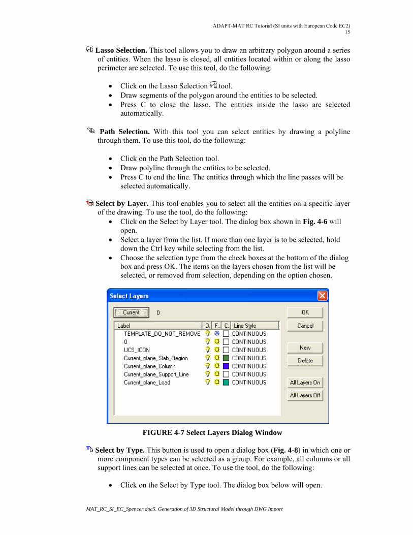
Select by Layer. This tool enables you to select all the entities on a specific layer of the drawing. To use the tool, do the following:
Click on the Select by Layer tool. The dialog box shown in Fig. 4-6 will open.
Select a layer from the list. If more than one layer is to be selected, hold down the Ctrl key while selecting from the list.
Choose the selection type from the check boxes at the bottom of the dialog box and press OK. The items on the layers chosen from the list will be selected, or removed from selection, depending on the option chosen.
FIGURE 4-7 Select Layers Dialog Window
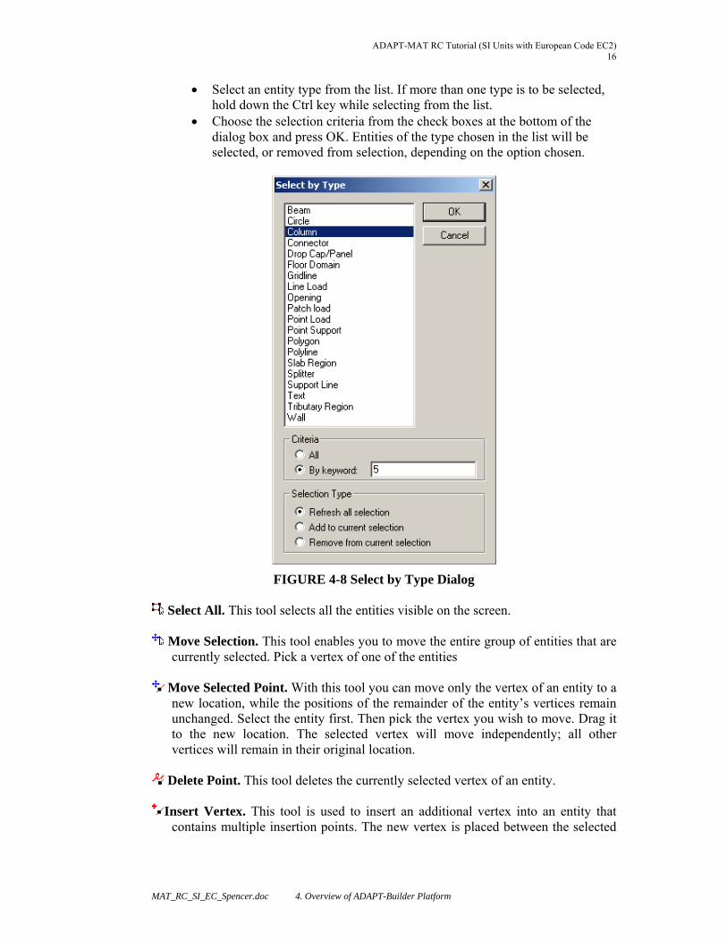
Select by Type. This button is used to open a dialog box (Fig. 4-8) in which one or more component types can be selected as a group. For example, all columns or all support lines can be selected at once. To use the tool, do the following:
Click on the Select by Type tool. The dialog box below will open.
ADAPT-MAT RC Tutorial (SI Units with European Code EC2) 16
MAT_RC_SI_EC_Spencer.doc 4. Overview of ADAPT-Builder Platform
Select an entity type from the list. If more than one type is to be selected, hold down the Ctrl key while selecting from the list.
Choose the selection criteria from the check boxes at the bottom of the dialog box and press OK. Entities of the type chosen in the list will be selected, or removed from selection, depending on the option chosen.
FIGURE 4-8 Select by Type Dialog
Select All. This tool selects all the entities visible on the screen.
Move Selection. This tool enables you to move the entire group of entities that are currently selected. Pick a vertex of one of the entities
Move Selected Point. With this tool you can move only the vertex of an entity to a
new location, while the positions of the remainder of the entity’s vertices remain unchanged. Select the entity first. Then pick the vertex you wish to move. Drag it to the new location. The selected vertex will move independently; all other vertices will remain in their original location.
Delete Point. This tool deletes the currently selected vertex of an entity.
Insert Vertex. This tool is used to insert an additional vertex into an entity that
contains multiple insertion points. The new vertex is placed between the selected
ADAPT-MAT RC Tutorial (SI units with European Code EC2) 17
MAT_RC_SI_EC_Spencer.doc5. Generation of 3D Structural Model through DWG Import
vertex and the previous vertex. If the first vertex is chosen, then the new vertex is added at this end. To add a vertex, do the following:
Select the entity. Click on the Insert Vertex tool. Click on one of the entities’ vertices. Another vertex will be added to the
entity, adjacent to the selected vertex.
Item’s Properties (Alt + Enter). This tool opens up the Properties dialog box for the selected entity. The properties may then be edited, as specified in other parts of this manual.
Group Selection. This tool creates a block containing all entities currently
selected. The block may then be dragged as one unit across the screen.
Explode Block. This tool breaks down a previously created block into its component. It also works with blocks of imported DWG or DXF files.
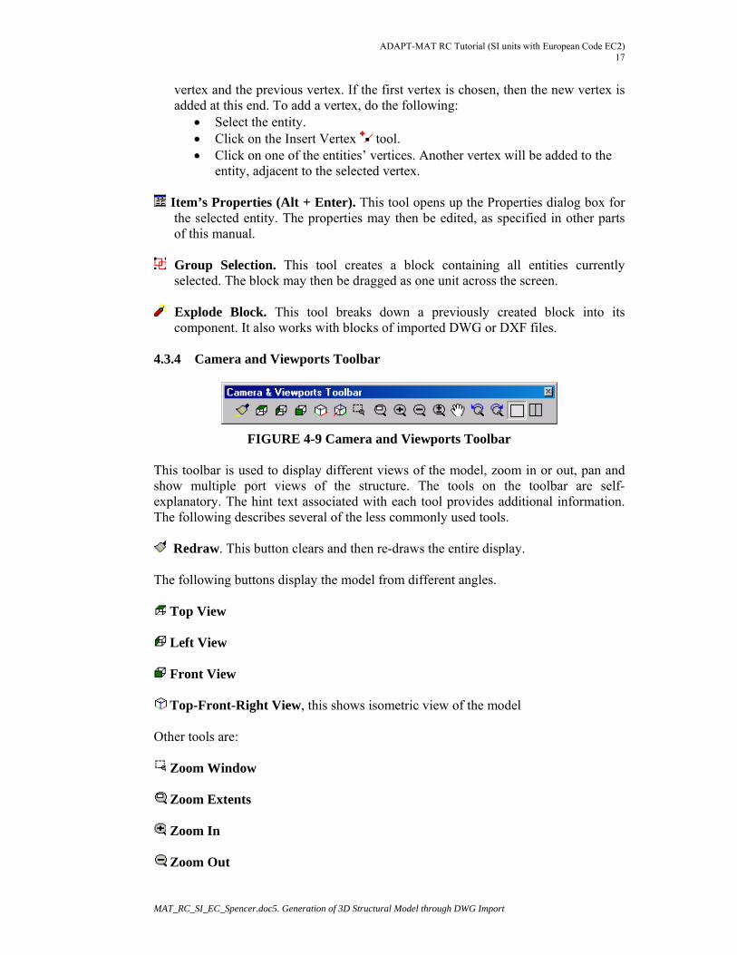
4.3.4 Camera and Viewports Toolbar
FIGURE 4-9 Camera and Viewports Toolbar This toolbar is used to display different views of the model, zoom in or out, pan and show multiple port views of the structure. The tools on the toolbar are self-explanatory. The hint text associated with each tool provides additional information. The following describes several of the less commonly used tools.
Redraw. This button clears and then re-draws the entire display. The following buttons display the model from different angles.
Top View
Left View
Front View
Top-Front-Right View, this shows isometric view of the model Other tools are:
Zoom Window
Zoom Extents
Zoom In
Zoom Out
ADAPT-MAT RC Tutorial (SI Units with European Code EC2) 18
MAT_RC_SI_EC_Spencer.doc 4. Overview of ADAPT-Builder Platform
Dynamic Zoom
Dynamic Pan
Undo Zoom / Pan
Redo Zoom / Pan
Single Viewport
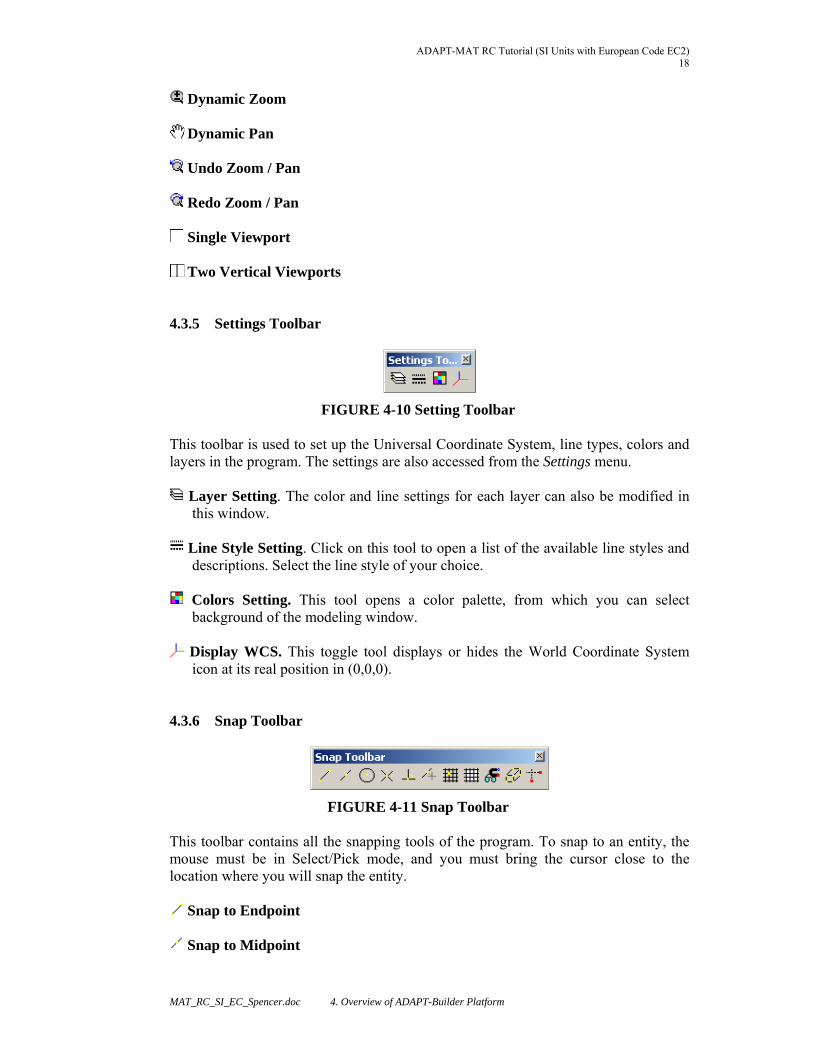
Two Vertical Viewports 4.3.5 Settings Toolbar
FIGURE 4-10 Setting Toolbar This toolbar is used to set up the Universal Coordinate System, line types, colors and layers in the program. The settings are also accessed from the Settings menu.
Layer Setting. The color and line settings for each layer can also be modified in this window.
Line Style Setting. Click on this tool to open a list of the available line styles and
descriptions. Select the line style of your choice.
Colors Setting. This tool opens a color palette, from which you can select background of the modeling window.
Display WCS. This toggle tool displays or hides the World Coordinate System
icon at its real position in (0,0,0). 4.3.6 Snap Toolbar
FIGURE 4-11 Snap Toolbar This toolbar contains all the snapping tools of the program. To snap to an entity, the mouse must be in Select/Pick mode, and you must bring the cursor close to the location where you will snap the entity.
Snap to Endpoint
Snap to Midpoint
ADAPT-MAT RC Tutorial (SI units with European Code EC2) 19
MAT_RC_SI_EC_Spencer.doc5. Generation of 3D Structural Model through DWG Import
Snap to Center
Snap to Intersection
Snap to Perpendicular. This tool forces the mouse cursor to snap to a target
entity, such that the entity being created will be positioned perpendicular to its target.
Snap to Nearest
Snap to Grid. This tool forces the mouse cursor to snap to the nearest grid point.
Grid Settings. This tool opens the Grid Settings dialog box where grid spacing,
angle and other parameters can be set.
Snap Settings. This tool opens the Snap Settings dialog box, where all snapping features may be selected or deselected.
Snap to Vertices of a Component. Using the previously described tools, you will
not be able to snap arbitrarily to the vertices or edges of structural components, such as a beam. Since a structural component that is displayed as solid is defined by its insertion points, the insertion points will not necessarily be the vertices or edges of the entity. By clicking on the above tool, you can make the vertices and edges of all the structural components of your project capable of being snapped to.
Note: Caution should be used when working with this tool. In order for a structural component to be correctly accounted for, in most instances it must be connected to other structural components through its insertion point. That is to say, the components must snap together at their insertion points.
Create/Draw Orthogonal. This tool forces the entity being drawn or created to be
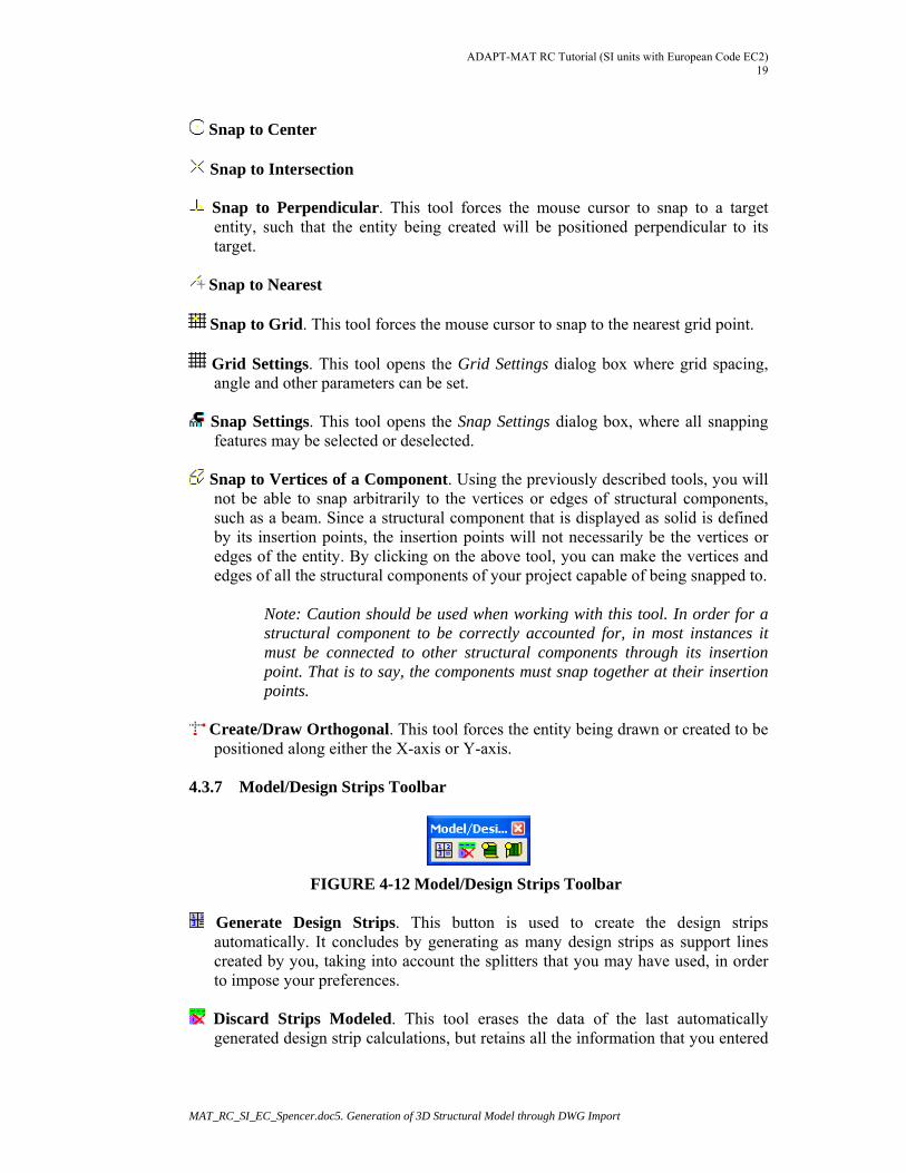
positioned along either the X-axis or Y-axis. 4.3.7 Model/Design Strips Toolbar
FIGURE 4-12 Model/Design Strips Toolbar
Generate Design Strips. This button is used to create the design strips automatically. It concludes by generating as many design strips as support lines created by you, taking into account the splitters that you may have used, in order to impose your preferences.
Discard Strips Modeled. This tool erases the data of the last automatically
generated design strip calculations, but retains all the information that you entered
ADAPT-MAT RC Tutorial (SI Units with European Code EC2) 20
MAT_RC_SI_EC_Spencer.doc 4. Overview of ADAPT-Builder Platform
manually, such as support lines and splitters. This tool is generally used when you decide to modify design strips calculated by the program.
Display Strip X
Display Strip Y
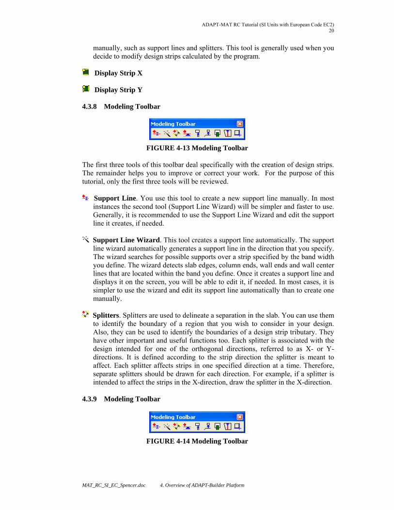
4.3.8 Modeling Toolbar
FIGURE 4-13 Modeling Toolbar The first three tools of this toolbar deal specifically with the creation of design strips. The remainder helps you to improve or correct your work. For the purpose of this tutorial, only the first three tools will be reviewed.
Support Line. You use this tool to create a new support line manually. In most instances the second tool (Support Line Wizard) will be simpler and faster to use. Generally, it is recommended to use the Support Line Wizard and edit the support line it creates, if needed.
Support Line Wizard. This tool creates a support line automatically. The support
line wizard automatically generates a support line in the direction that you specify. The wizard searches for possible supports over a strip specified by the band width you define. The wizard detects slab edges, column ends, wall ends and wall center lines that are located within the band you define. Once it creates a support line and displays it on the screen, you will be able to edit it, if needed. In most cases, it is simpler to use the wizard and edit its support line automatically than to create one manually.
Splitters. Splitters are used to delineate a separation in the slab. You can use them
to identify the boundary of a region that you wish to consider in your design. Also, they can be used to identify the boundaries of a design strip tributary. They have other important and useful functions too. Each splitter is associated with the design intended for one of the orthogonal directions, referred to as X- or Y-directions. It is defined according to the strip direction the splitter is meant to affect. Each splitter affects strips in one specified direction at a time. Therefore, separate splitters should be drawn for each direction. For example, if a splitter is intended to affect the strips in the X-direction, draw the splitter in the X-direction.
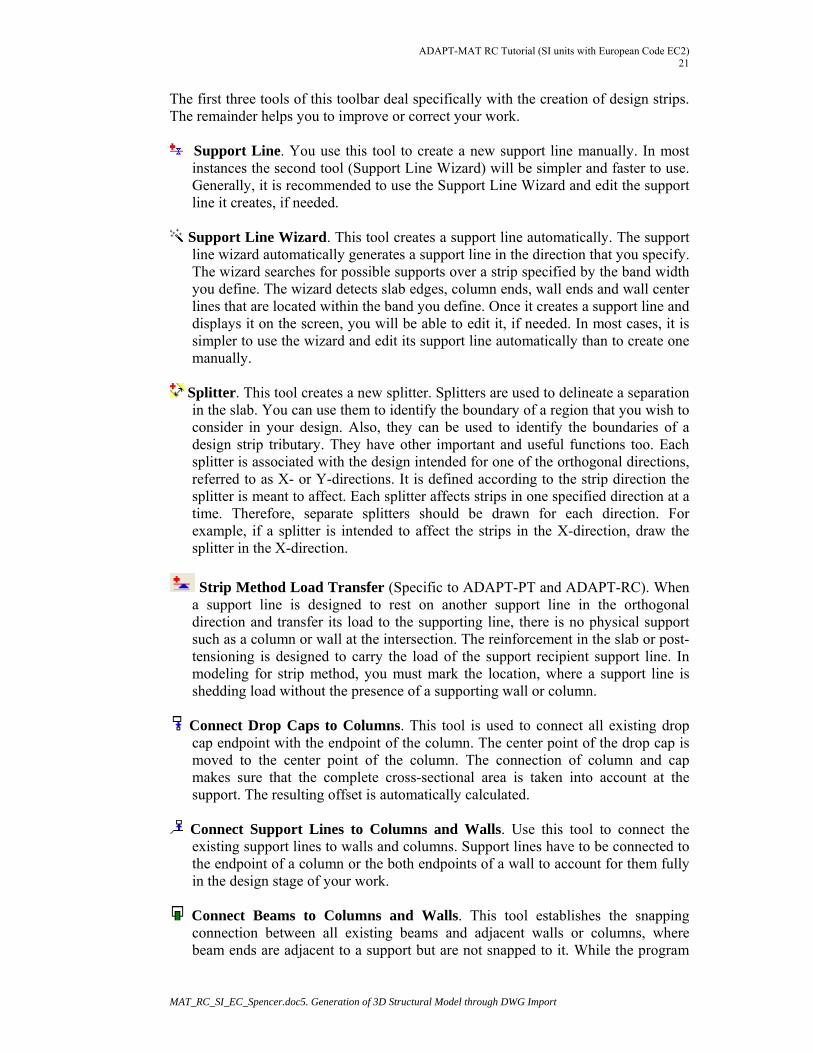
4.3.9 Modeling Toolbar
FIGURE 4-14 Modeling Toolbar
ADAPT-MAT RC Tutorial (SI units with European Code EC2) 21
MAT_RC_SI_EC_Spencer.doc5. Generation of 3D Structural Model through DWG Import
The first three tools of this toolbar deal specifically with the creation of design strips. The remainder helps you to improve or correct your work.
Support Line. You use this tool to create a new support line manually. In most instances the second tool (Support Line Wizard) will be simpler and faster to use. Generally, it is recommended to use the Support Line Wizard and edit the support line it creates, if needed.
Support Line Wizard. This tool creates a support line automatically. The support
line wizard automatically generates a support line in the direction that you specify. The wizard searches for possible supports over a strip specified by the band width you define. The wizard detects slab edges, column ends, wall ends and wall center lines that are located within the band you define. Once it creates a support line and displays it on the screen, you will be able to edit it, if needed. In most cases, it is simpler to use the wizard and edit its support line automatically than to create one manually.
Splitter. This tool creates a new splitter. Splitters are used to delineate a separation
in the slab. You can use them to identify the boundary of a region that you wish to consider in your design. Also, they can be used to identify the boundaries of a design strip tributary. They have other important and useful functions too. Each splitter is associated with the design intended for one of the orthogonal directions, referred to as X- or Y-directions. It is defined according to the strip direction the splitter is meant to affect. Each splitter affects strips in one specified direction at a time. Therefore, separate splitters should be drawn for each direction. For example, if a splitter is intended to affect the strips in the X-direction, draw the splitter in the X-direction.
Strip Method Load Transfer (Specific to ADAPT-PT and ADAPT-RC). When a support line is designed to rest on another support line in the orthogonal direction and transfer its load to the supporting line, there is no physical support such as a column or wall at the intersection. The reinforcement in the slab or post-tensioning is designed to carry the load of the support recipient support line. In modeling for strip method, you must mark the location, where a support line is shedding load without the presence of a supporting wall or column.
Connect Drop Caps to Columns. This tool is used to connect all existing drop
cap endpoint with the endpoint of the column. The center point of the drop cap is moved to the center point of the column. The connection of column and cap makes sure that the complete cross-sectional area is taken into account at the support. The resulting offset is automatically calculated.
Connect Support Lines to Columns and Walls. Use this tool to connect the
existing support lines to walls and columns. Support lines have to be connected to the endpoint of a column or the both endpoints of a wall to account for them fully in the design stage of your work.
Connect Beams to Columns and Walls. This tool establishes the snapping
connection between all existing beams and adjacent walls or columns, where beam ends are adjacent to a support but are not snapped to it. While the program
ADAPT-MAT RC Tutorial (SI Units with European Code EC2) 22
MAT_RC_SI_EC_Spencer.doc 4. Overview of ADAPT-Builder Platform
can handle a beam that terminates short of a column, for proper treatment of beams that are connected to columns you should use the Snap option. This tool will search for such instances in your model and will establish the connection.
Support Lines Extension. This tool extends all existing support lines to the edges
of the slab. Use this tool if you created a support line manually, as it is likely you missed snapping its ends to the slab edges. If the distance of the support line end to a slab edge is more than the program’s tolerance, you must do the connection manually.
Align Structural Components. This tool improves the quality of your modeling.
You can automatically adjust the location of a wall or column that you have drawn to line up with the face of slab.
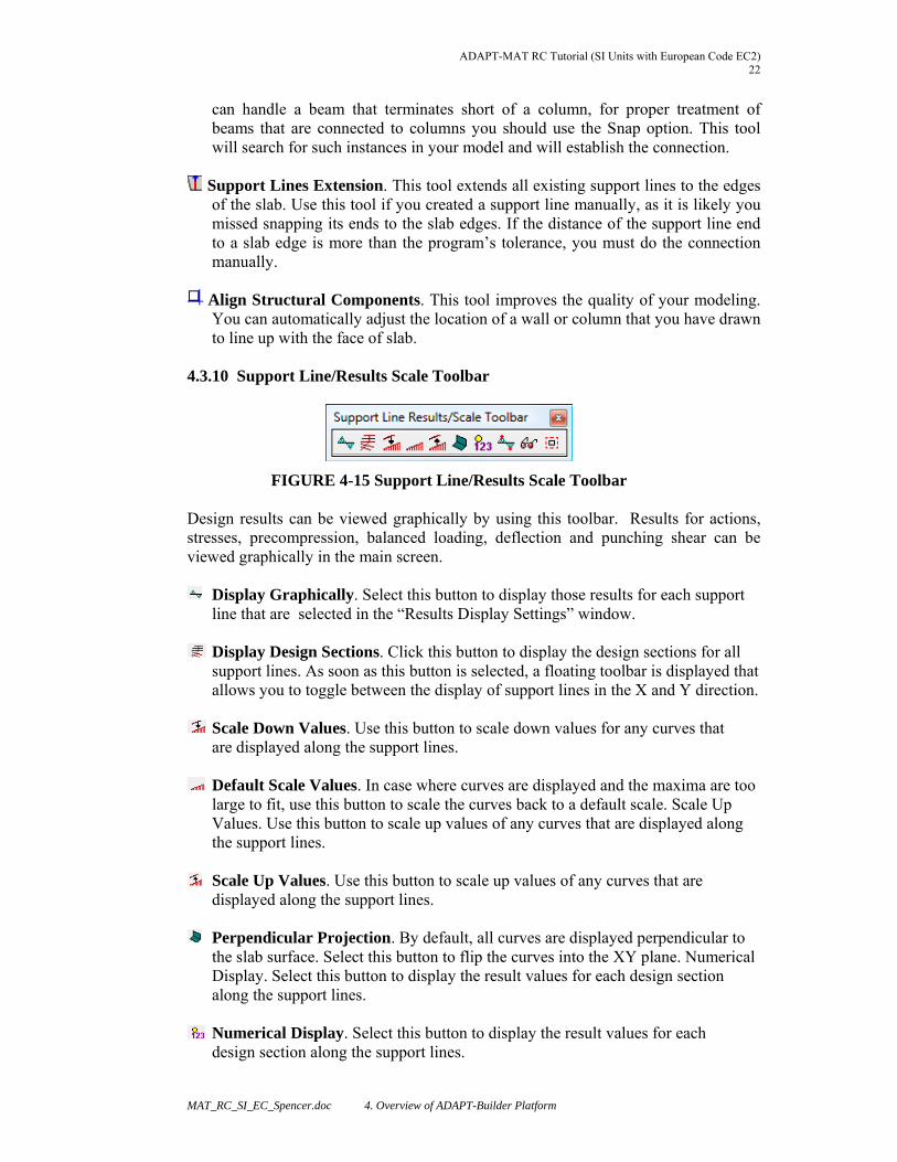
4.3.10 Support Line/Results Scale Toolbar
FIGURE 4-15 Support Line/Results Scale Toolbar Design results can be viewed graphically by using this toolbar. Results for actions, stresses, precompression, balanced loading, deflection and punching shear can be viewed graphically in the main screen.
Display Graphically. Select this button to display those results for each support line that are selected in the “Results Display Settings” window.
Display Design Sections. Click this button to display the design sections for all support lines. As soon as this button is selected, a floating toolbar is displayed that allows you to toggle between the display of support lines in the X and Y direction.
Scale Down Values. Use this button to scale down values for any curves that are displayed along the support lines.
Default Scale Values. In case where curves are displayed and the maxima are too large to fit, use this button to scale the curves back to a default scale. Scale Up Values. Use this button to scale up values of any curves that are displayed along the support lines.
Scale Up Values. Use this button to scale up values of any curves that are
displayed along the support lines.
Perpendicular Projection. By default, all curves are displayed perpendicular to the slab surface. Select this button to flip the curves into the XY plane. Numerical Display. Select this button to display the result values for each design section along the support lines.
Numerical Display. Select this button to display the result values for each design section along the support lines.
ADAPT-MAT RC Tutorial (SI units with European Code EC2) 23
MAT_RC_SI_EC_Spencer.doc5. Generation of 3D Structural Model through DWG Import
Display Min/Max Values. Click this button to only display the minimum and maximum result values along the support lines.
Result Display Settings. Select this button to open the “Result Display Settings” window.
Display Punching Shear Design Outcome. Once you have executed the punching shear design, the results can be reviewed in the model by clicking on this button.
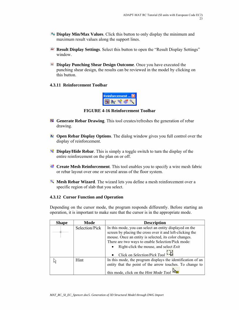
4.3.11 Reinforcement Toolbar
FIGURE 4-16 Reinforcement Toolbar
Generate Rebar Drawing. This tool creates/refreshes the generation of rebar drawing.
Open Rebar Display Options. The dialog window gives you full control over the
display of reinforcement.
Display/Hide Rebar. This is simply a toggle switch to turn the display of the entire reinforcement on the plan on or off.
Create Mesh Reinforcement. This tool enables you to specify a wire mesh fabric
or rebar layout over one or several areas of the floor system.
Mesh Rebar Wizard. The wizard lets you define a mesh reinforcement over a specific region of slab that you select.
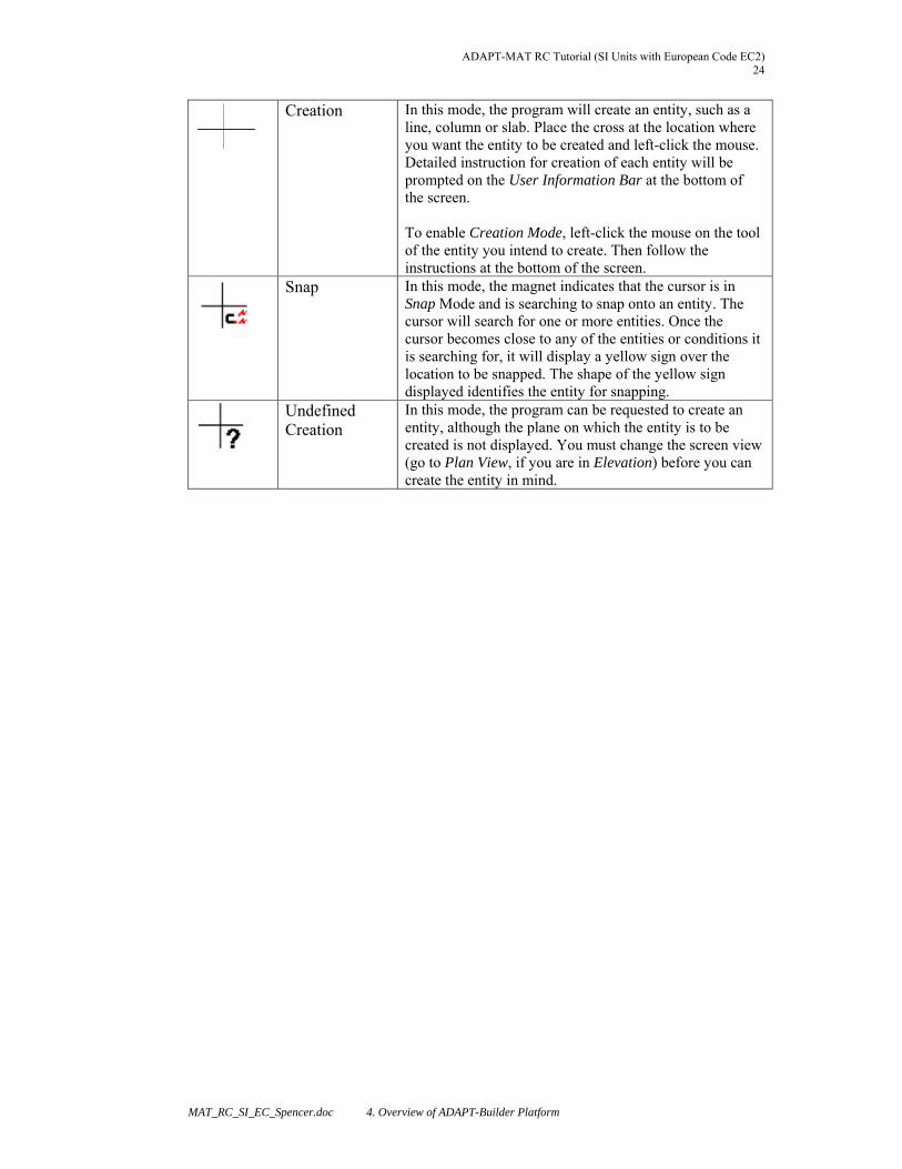
4.3.12 Cursor Function and Operation Depending on the cursor mode, the program responds differently. Before starting an operation, it is important to make sure that the cursor is in the appropriate mode.
Shape Mode Description
Selection/Pick In this mode, you can select an entity displayed on the screen by placing the cross over it and left-clicking the mouse. Once an entity is selected, its color changes. There are two ways to enable Selection/Pick mode:
Right-click the mouse, and select Exit
Click on Selection/Pick Tool
Hint In this mode, the program displays the identification of an
entity that the point of the arrow touches. To change to
this mode, click on the Hint Mode Tool
ADAPT-MAT RC Tutorial (SI Units with European Code EC2) 24
MAT_RC_SI_EC_Spencer.doc 4. Overview of ADAPT-Builder Platform
Creation In this mode, the program will create an entity, such as a line, column or slab. Place the cross at the location where you want the entity to be created and left-click the mouse. Detailed instruction for creation of each entity will be prompted on the User Information Bar at the bottom of the screen. To enable Creation Mode, left-click the mouse on the tool of the entity you intend to create. Then follow the instructions at the bottom of the screen.
Snap
In this mode, the magnet indicates that the cursor is in Snap Mode and is searching to snap onto an entity. The cursor will search for one or more entities. Once the cursor becomes close to any of the entities or conditions it is searching for, it will display a yellow sign over the location to be snapped. The shape of the yellow sign displayed identifies the entity for snapping.
Undefined Creation
In this mode, the program can be requested to create an entity, although the plane on which the entity is to be created is not displayed. You must change the screen view (go to Plan View, if you are in Elevation) before you can create the entity in mind.
ADAPT-MAT RC Tutorial (SI units with European Code EC2) 25
MAT_RC_SI_EC_Spencer.doc5. Generation of 3D Structural Model through DWG Import
5 GENERATION OF A 3D STRUCTURAL MODEL THROUGH DWG IMPORT
The steps to follow for the generation of a 3D structural model of the floor system through import of a drawing file are detailed below. This includes transformation of 2D polygonal shapes to 3D structural components.
5.1 FIRST DRAWING IMPORT At this step, the simplified structural or architectural drawing will be imported to the Builder program and converted to a structural model. Follow the steps below:
Open the Builder program in MAT mode with SI unit system (as shown in Fig. 4-2).
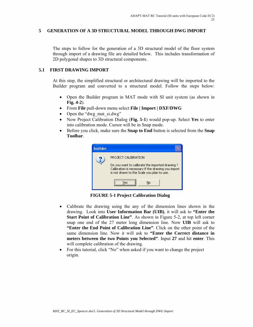
From File pull-down menu select File | Import | DXF/DWG Open the “dwg_mat_si.dwg” Now Project Calibration Dialog (Fig. 5-1) would pop-up. Select Yes to enter
into calibration mode. Cursor will be in Snap mode. Before you click, make sure the Snap to End button is selected from the Snap
Toolbar.
FIGURE 5-1 Project Calibration Dialog
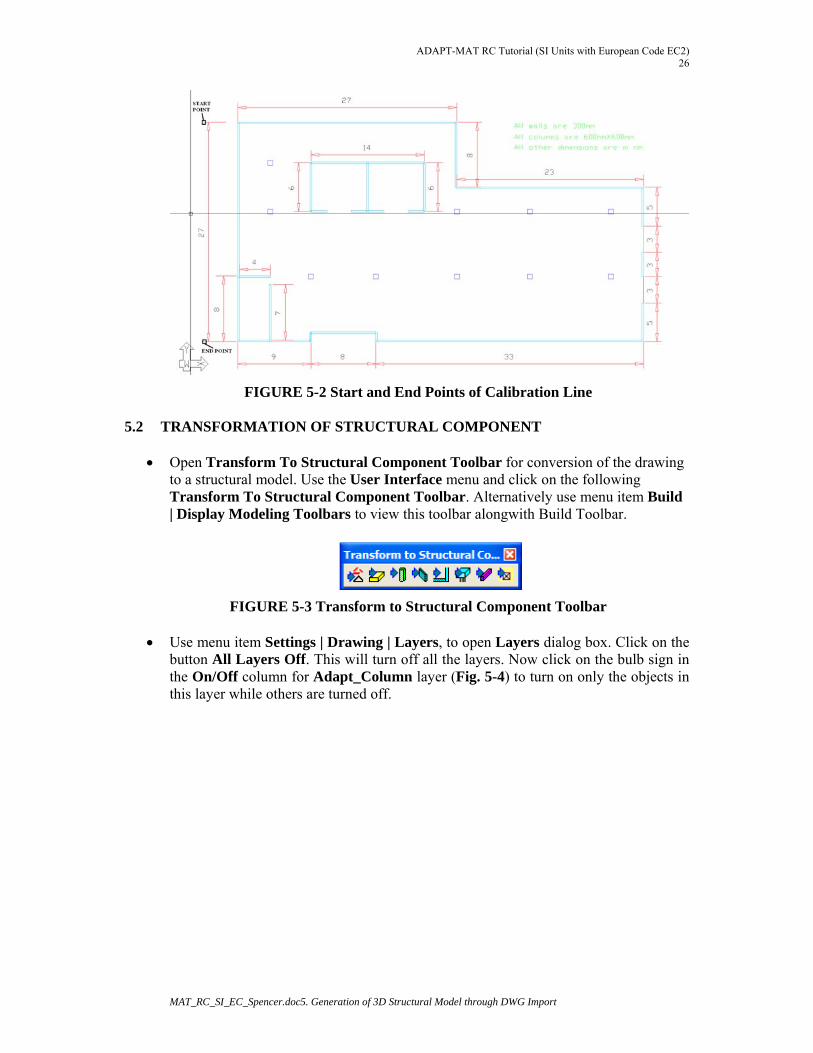
Calibrate the drawing using the any of the dimension lines shown in the drawing. Look into User Information Bar (UIB), it will ask to “Enter the Start Point of Calibration Line”. As shown in Figure 5-2, at top left corner snap one end of the 27 meter long dimension line. Now UIB will ask to “Enter the End Point of Calibration Line”. Click on the other point of the same dimension line. Now it will ask to “Enter the Correct distance in meters between the two Points you Selected”. Input 27 and hit enter. This will complete calibration of the drawing.
For this tutorial, click “No” when asked if you want to change the project origin.
ADAPT-MAT RC Tutorial (SI Units with European Code EC2) 26
MAT_RC_SI_EC_Spencer.doc5. Generation of 3D Structural Model through DWG Import
FIGURE 5-2 Start and End Points of Calibration Line
5.2 TRANSFORMATION OF STRUCTURAL COMPONENT
Open Transform To Structural Component Toolbar for conversion of the drawing to a structural model. Use the User Interface menu and click on the following Transform To Structural Component Toolbar. Alternatively use menu item Build | Display Modeling Toolbars to view this toolbar alongwith Build Toolbar.
FIGURE 5-3 Transform to Structural Component Toolbar
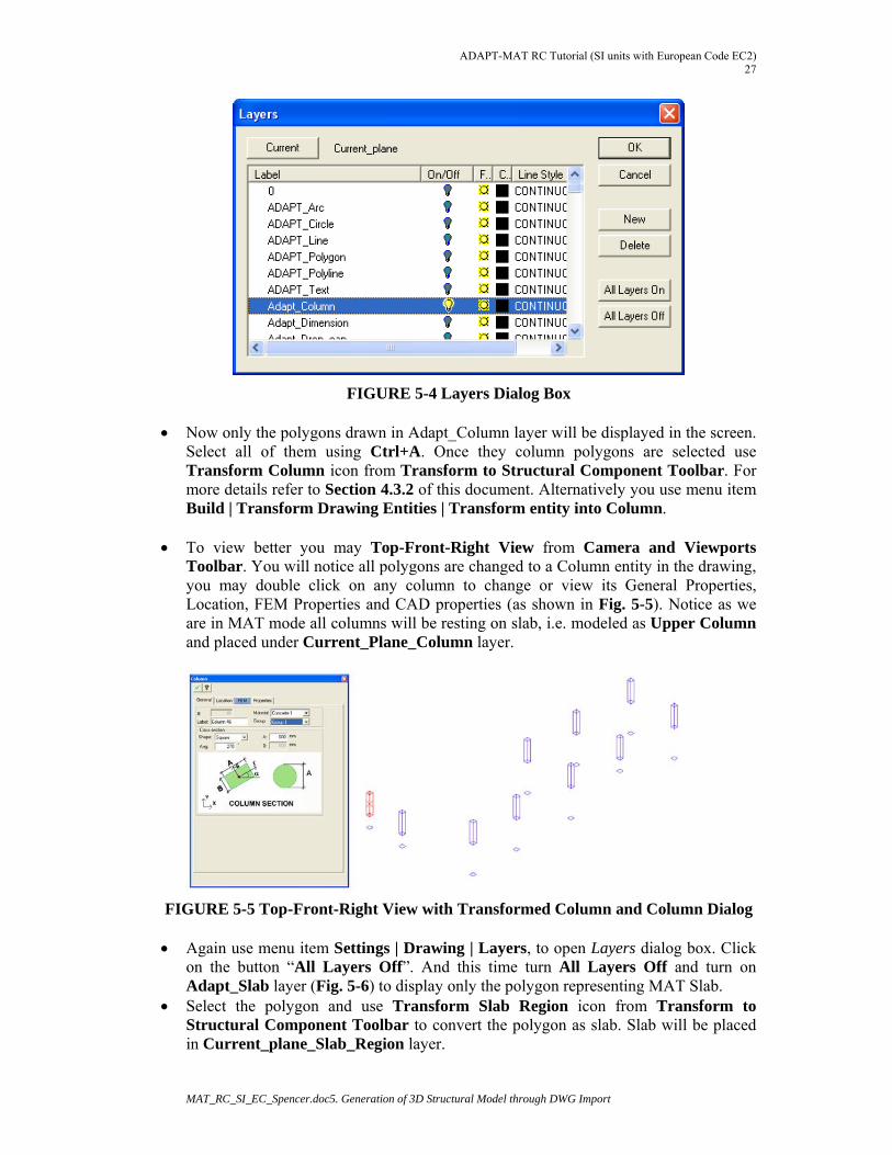
Use menu item Settings | Drawing | Layers, to open Layers dialog box. Click on the button All Layers Off. This will turn off all the layers. Now click on the bulb sign in the On/Off column for Adapt_Column layer (Fig. 5-4) to turn on only the objects in this layer while others are turned off.
ADAPT-MAT RC Tutorial (SI units with European Code EC2) 27
MAT_RC_SI_EC_Spencer.doc5. Generation of 3D Structural Model through DWG Import
FIGURE 5-4 Layers Dialog Box Now only the polygons drawn in Adapt_Column layer will be displayed in the screen.
Select all of them using Ctrl+A. Once they column polygons are selected use Transform Column icon from Transform to Structural Component Toolbar. For more details refer to Section 4.3.2 of this document. Alternatively you use menu item Build | Transform Drawing Entities | Transform entity into Column.
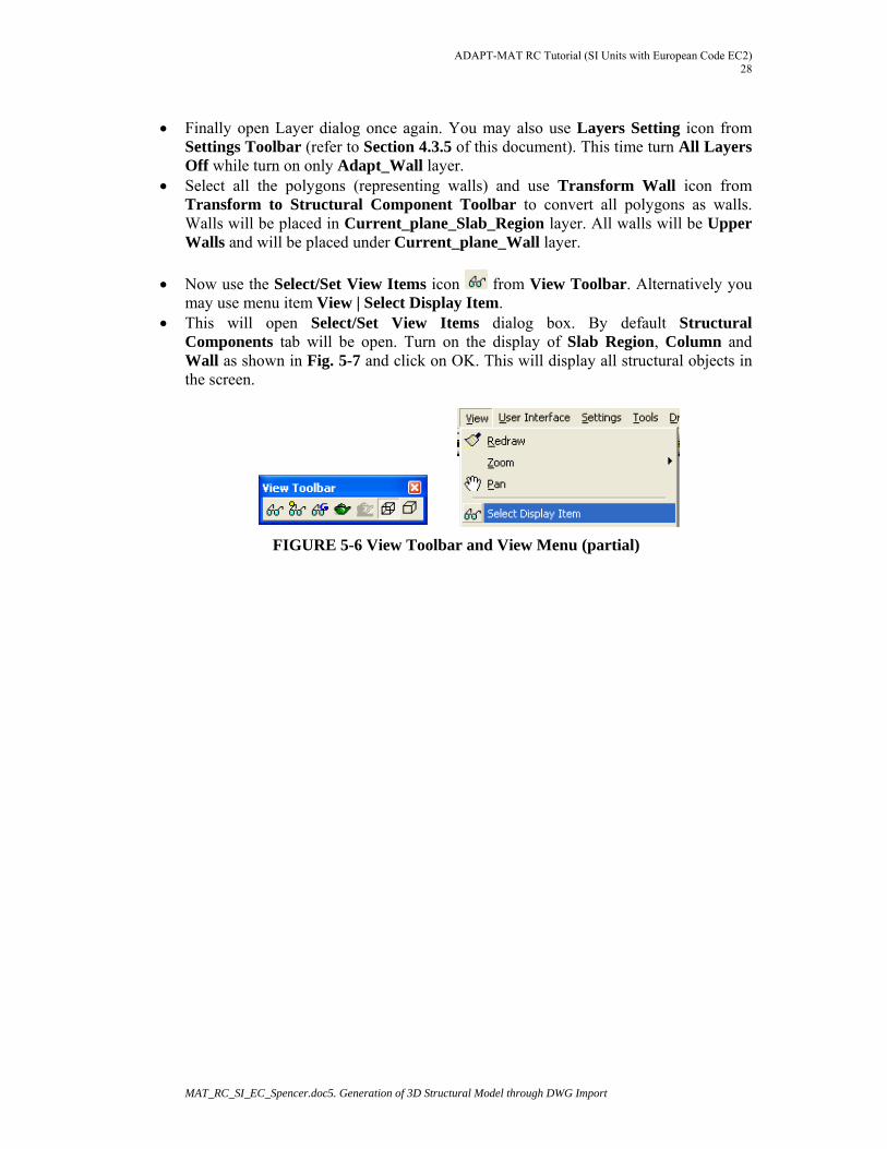
To view better you may Top-Front-Right View from Camera and Viewports
Toolbar. You will notice all polygons are changed to a Column entity in the drawing, you may double click on any column to change or view its General Properties, Location, FEM Properties and CAD properties (as shown in Fig. 5-5). Notice as we are in MAT mode all columns will be resting on slab, i.e. modeled as Upper Column and placed under Current_Plane_Column layer.
FIGURE 5-5 Top-Front-Right View with Transformed Column and Column Dialog
Again use menu item Settings | Drawing | Layers, to open Layers dialog box. Click on the button “All Layers Off”. And this time turn All Layers Off and turn on Adapt_Slab layer (Fig. 5-6) to display only the polygon representing MAT Slab.
Select the polygon and use Transform Slab Region icon from Transform to Structural Component Toolbar to convert the polygon as slab. Slab will be placed in Current_plane_Slab_Region layer.
ADAPT-MAT RC Tutorial (SI Units with European Code EC2) 28
MAT_RC_SI_EC_Spencer.doc5. Generation of 3D Structural Model through DWG Import
Finally open Layer dialog once again. You may also use Layers Setting icon from
Settings Toolbar (refer to Section 4.3.5 of this document). This time turn All Layers Off while turn on only Adapt_Wall layer.
Select all the polygons (representing walls) and use Transform Wall icon from Transform to Structural Component Toolbar to convert all polygons as walls. Walls will be placed in Current_plane_Slab_Region layer. All walls will be Upper Walls and will be placed under Current_plane_Wall layer.
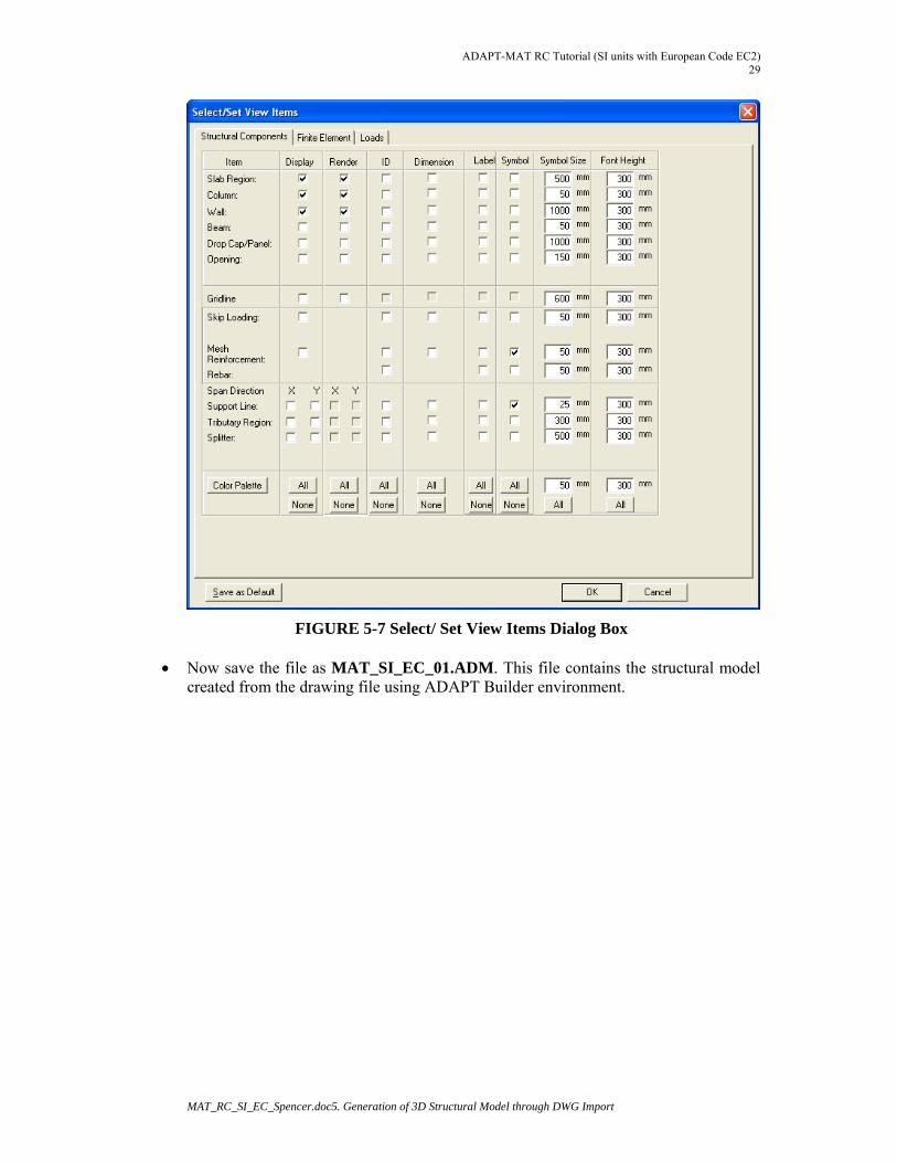
Now use the Select/Set View Items icon from View Toolbar. Alternatively you may use menu item View | Select Display Item.
This will open Select/Set View Items dialog box. By default Structural Components tab will be open. Turn on the display of Slab Region, Column and Wall as shown in Fig. 5-7 and click on OK. This will display all structural objects in the screen.
FIGURE 5-6 View Toolbar and View Menu (partial)
ADAPT-MAT RC Tutorial (SI units with European Code EC2) 29
MAT_RC_SI_EC_Spencer.doc5. Generation of 3D Structural Model through DWG Import
FIGURE 5-7 Select/ Set View Items Dialog Box
Now save the file as MAT_SI_EC_01.ADM. This file contains the structural model created from the drawing file using ADAPT Builder environment.
ADAPT-MAT RC Tutorial (SI Units with European Code EC2) 30
MAT_RC_SI_EC_Spencer.doc 6. Material, Soil Support, Criteria and Loadings
6 MATERIAL, SOIL SUPPORT CRITERIA AND LOADINGS
Open MAT_SI_EC_01.ADM file if you have closed it. If you have completed all steps successfully as specified in earlier section, you may continue with the file you created and saved to your hard-disk. Otherwise please open the file with same name provided to you upon request from ADAPT Support.
6.1 SET AND ASSIGN MATERIAL PROPERTIES
6.1.1 Set and Assign Multiple Concrete Material
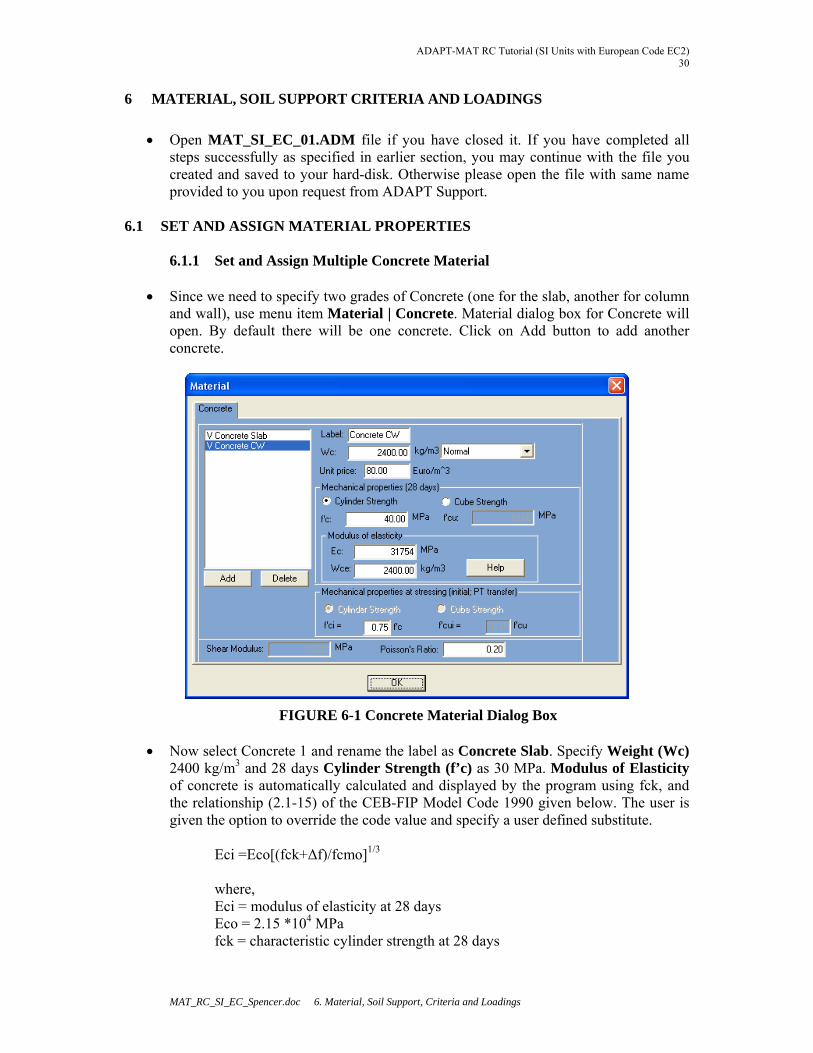
Since we need to specify two grades of Concrete (one for the slab, another for column and wall), use menu item Material | Concrete. Material dialog box for Concrete will open. By default there will be one concrete. Click on Add button to add another concrete.
FIGURE 6-1 Concrete Material Dialog Box
Now select Concrete 1 and rename the label as Concrete Slab. Specify Weight (Wc) 2400 kg/m3 and 28 days Cylinder Strength (f’c) as 30 MPa. Modulus of Elasticity of concrete is automatically calculated and displayed by the program using fck, and the relationship (2.1-15) of the CEB-FIP Model Code 1990 given below. The user is given the option to override the code value and specify a user defined substitute.
Eci =Eco[(fck+Δf)/fcmo]1/3
where, Eci = modulus of elasticity at 28 days Eco = 2.15 *104 MPa fck = characteristic cylinder strength at 28 days
ADAPT-MAT RC Tutorial (SI units with European Code EC2) 31
MAT_RC_SI_EC_Spencer.doc 6. Material, Soil Support, Criteria and Loadings
Δf = 8 MPa fcmo = 10 MPa
Similarly select Concrete 2 and rename the label as Concrete CW. Specify Weight
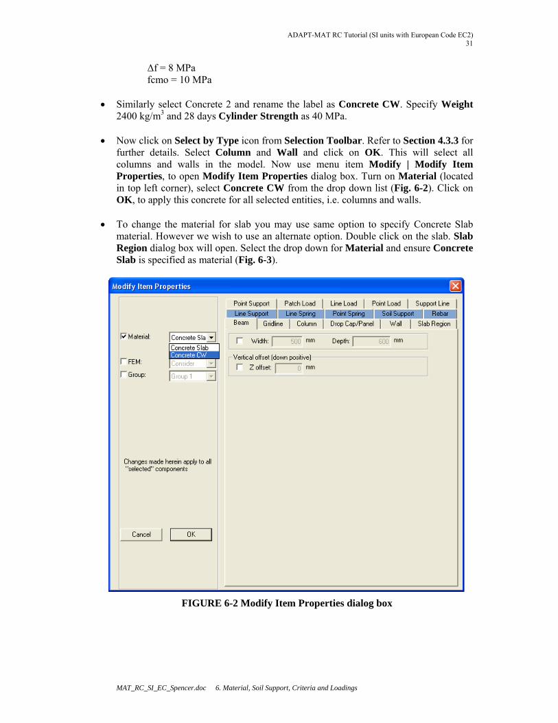
2400 kg/m3 and 28 days Cylinder Strength as 40 MPa. Now click on Select by Type icon from Selection Toolbar. Refer to Section 4.3.3 for
further details. Select Column and Wall and click on OK. This will select all columns and walls in the model. Now use menu item Modify | Modify Item Properties, to open Modify Item Properties dialog box. Turn on Material (located in top left corner), select Concrete CW from the drop down list (Fig. 6-2). Click on OK, to apply this concrete for all selected entities, i.e. columns and walls.
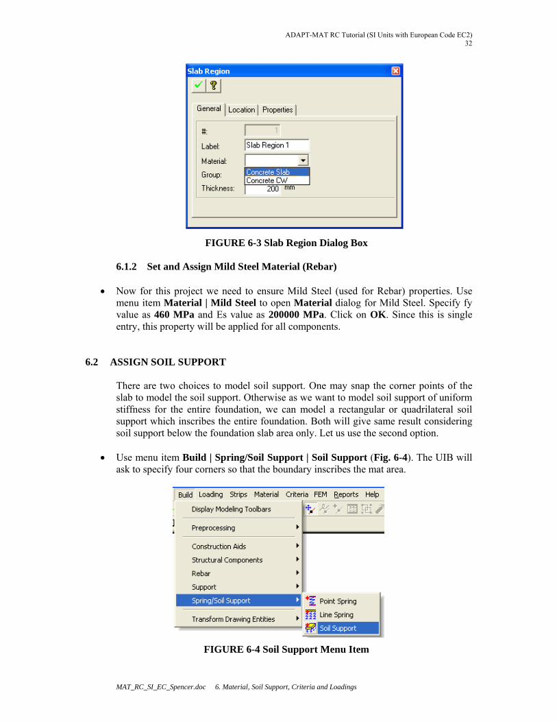
To change the material for slab you may use same option to specify Concrete Slab
material. However we wish to use an alternate option. Double click on the slab. Slab Region dialog box will open. Select the drop down for Material and ensure Concrete Slab is specified as material (Fig. 6-3).
FIGURE 6-2 Modify Item Properties dialog box
ADAPT-MAT RC Tutorial (SI Units with European Code EC2) 32
MAT_RC_SI_EC_Spencer.doc 6. Material, Soil Support, Criteria and Loadings
FIGURE 6-3 Slab Region Dialog Box
6.1.2 Set and Assign Mild Steel Material (Rebar) Now for this project we need to ensure Mild Steel (used for Rebar) properties. Use
menu item Material | Mild Steel to open Material dialog for Mild Steel. Specify fy value as 460 MPa and Es value as 200000 MPa. Click on OK. Since this is single entry, this property will be applied for all components.
6.2 ASSIGN SOIL SUPPORT
There are two choices to model soil support. One may snap the corner points of the slab to model the soil support. Otherwise as we want to model soil support of uniform stiffness for the entire foundation, we can model a rectangular or quadrilateral soil support which inscribes the entire foundation. Both will give same result considering soil support below the foundation slab area only. Let us use the second option.
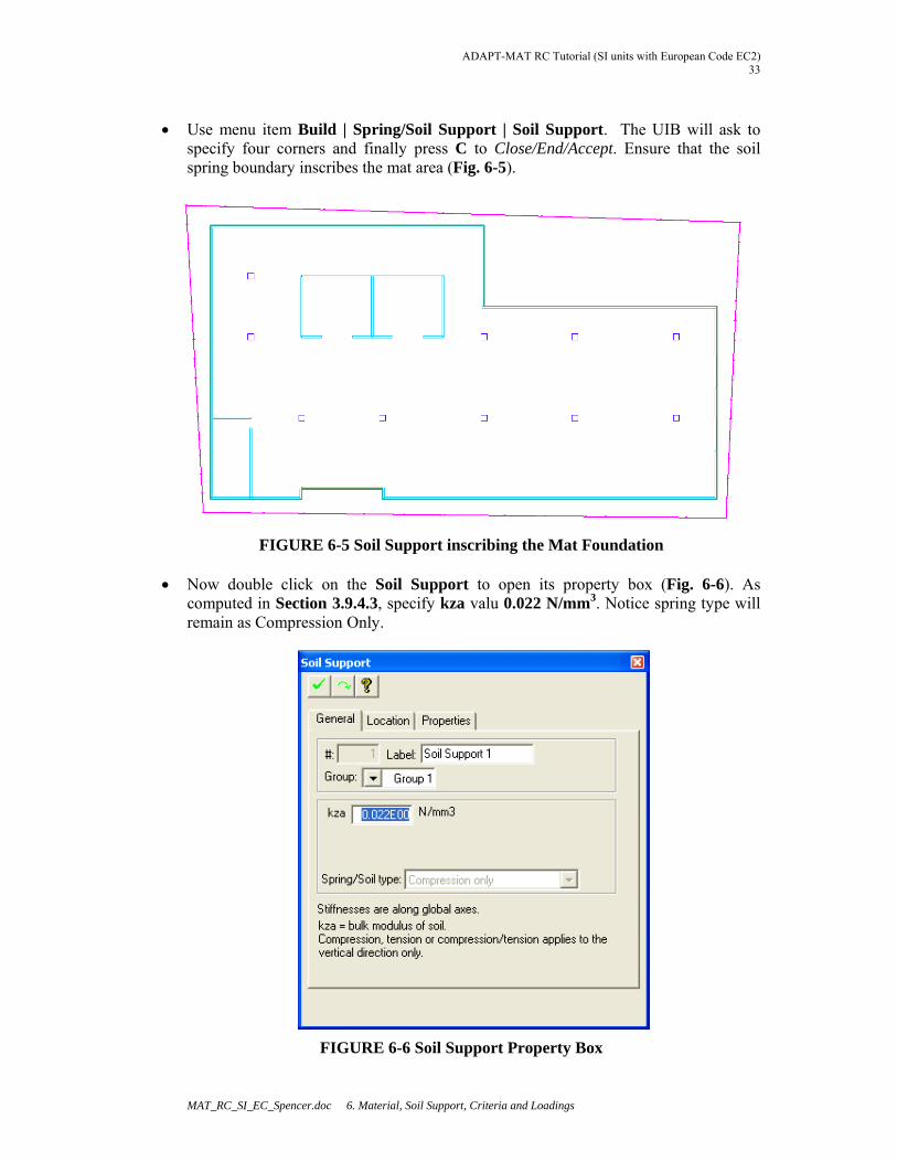
Use menu item Build | Spring/Soil Support | Soil Support (Fig. 6-4). The UIB will
ask to specify four corners so that the boundary inscribes the mat area.
FIGURE 6-4 Soil Support Menu Item
ADAPT-MAT RC Tutorial (SI units with European Code EC2) 33
MAT_RC_SI_EC_Spencer.doc 6. Material, Soil Support, Criteria and Loadings
Use menu item Build | Spring/Soil Support | Soil Support. The UIB will ask to
specify four corners and finally press C to Close/End/Accept. Ensure that the soil spring boundary inscribes the mat area (Fig. 6-5).
FIGURE 6-5 Soil Support inscribing the Mat Foundation
Now double click on the Soil Support to open its property box (Fig. 6-6). As computed in Section 3.9.4.3, specify kza valu 0.022 N/mm3. Notice spring type will remain as Compression Only.
FIGURE 6-6 Soil Support Property Box
ADAPT-MAT RC Tutorial (SI Units with European Code EC2) 34
MAT_RC_SI_EC_Spencer.doc 6. Material, Soil Support, Criteria and Loadings
6.3 SET CRITERIA
Let us now set the design criteria for this project. This should be done before we define loading as automatic load combinations are generated based on the design code selected by the user.
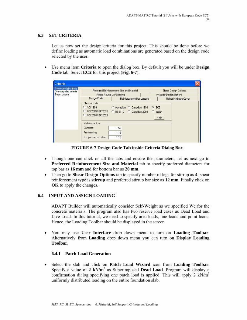
Use menu item Criteria to open the dialog box. By default you will be under Design Code tab. Select EC2 for this project (Fig. 6-7).
FIGURE 6-7 Design Code Tab inside Criteria Dialog Box
Though one can click on all the tabs and ensure the parameters, let us next go to Preferred Reinforcement Size and Material tab to specify preferred diameters for top bar as 16 mm and for bottom bar as 20 mm.
Then go to Shear Design Options tab to specify number of legs for stirrup as 4; shear reinforcement type is stirrup and preferred stirrup bar size as 12 mm. Finally click on OK to apply the changes.
6.4 INPUT AND ASSIGN LOADING ADAPT Builder will automatically consider Self-Weight as we specified Wc for the concrete materials. The program also has two reserve load cases as Dead Load and Live Load. In this tutorial, we need to specify area loads, line loads and point loads. Hence, the Loading Toolbar should be displayed in the screen.
You may use User Interface drop down menu to turn on Loading Toolbar. Alternatively from Loading drop down menu you can turn on Display Loading Toolbar.
6.4.1 Patch Load Generation
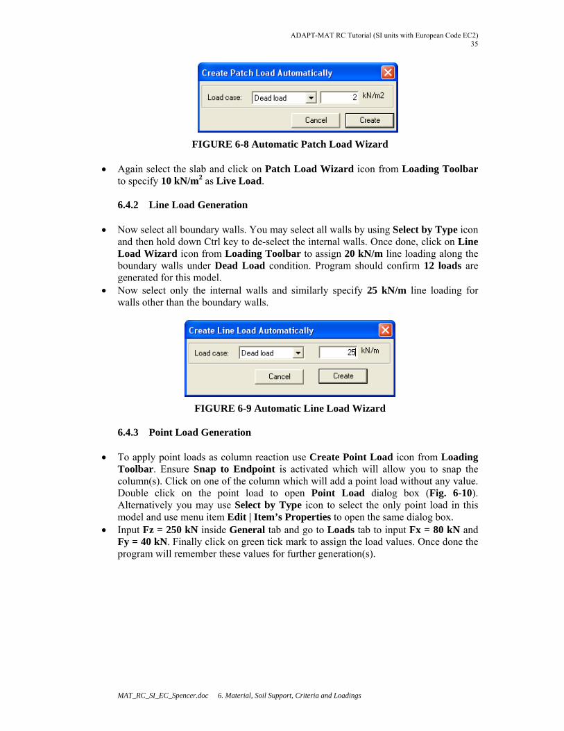
Select the slab and click on Patch Load Wizard icon from Loading Toolbar.
Specify a value of 2 kN/m2 as Superimposed Dead Load. Program will display a confirmation dialog specifying one patch load is applied. This will apply 2 kN/m2 uniformly distributed loading on the entire foundation slab.
ADAPT-MAT RC Tutorial (SI units with European Code EC2) 35
MAT_RC_SI_EC_Spencer.doc 6. Material, Soil Support, Criteria and Loadings
FIGURE 6-8 Automatic Patch Load Wizard
Again select the slab and click on Patch Load Wizard icon from Loading Toolbar to specify 10 kN/m2 as Live Load.
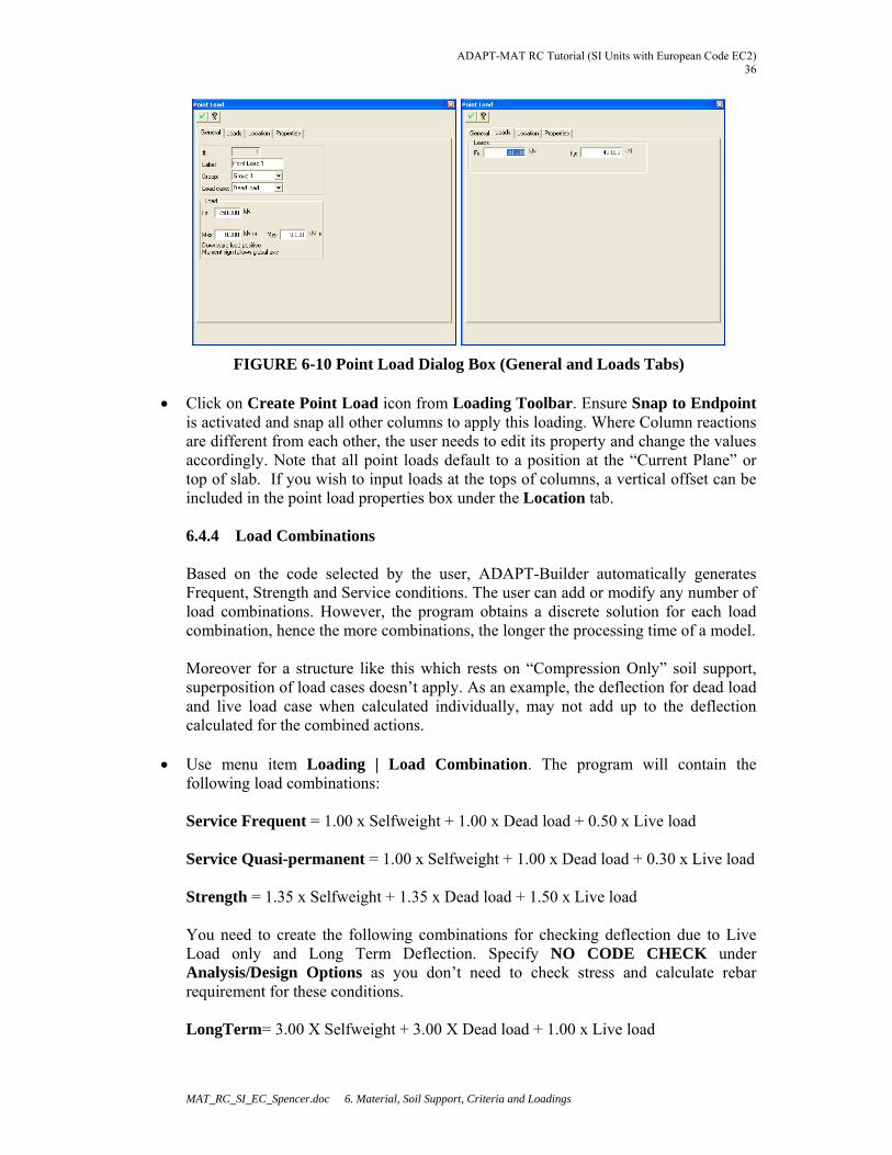
6.4.2 Line Load Generation
Now select all boundary walls. You may select all walls by using Select by Type icon
and then hold down Ctrl key to de-select the internal walls. Once done, click on Line Load Wizard icon from Loading Toolbar to assign 20 kN/m line loading along the boundary walls under Dead Load condition. Program should confirm 12 loads are generated for this model.
Now select only the internal walls and similarly specify 25 kN/m line loading for walls other than the boundary walls.
FIGURE 6-9 Automatic Line Load Wizard 6.4.3 Point Load Generation
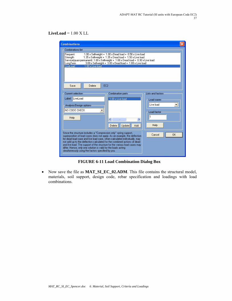
To apply point loads as column reaction use Create Point Load icon from Loading Toolbar. Ensure Snap to Endpoint is activated which will allow you to snap the column(s). Click on one of the column which will add a point load without any value. Double click on the point load to open Point Load dialog box (Fig. 6-10). Alternatively you may use Select by Type icon to select the only point load in this model and use menu item Edit | Item’s Properties to open the same dialog box.
Input Fz = 250 kN inside General tab and go to Loads tab to input Fx = 80 kN and Fy = 40 kN. Finally click on green tick mark to assign the load values. Once done the program will remember these values for further generation(s).
ADAPT-MAT RC Tutorial (SI Units with European Code EC2) 36
MAT_RC_SI_EC_Spencer.doc 6. Material, Soil Support, Criteria and Loadings
FIGURE 6-10 Point Load Dialog Box (General and Loads Tabs) Click on Create Point Load icon from Loading Toolbar. Ensure Snap to Endpoint
is activated and snap all other columns to apply this loading. Where Column reactions are different from each other, the user needs to edit its property and change the values accordingly. Note that all point loads default to a position at the “Current Plane” or top of slab. If you wish to input loads at the tops of columns, a vertical offset can be included in the point load properties box under the Location tab.
6.4.4 Load Combinations Based on the code selected by the user, ADAPT-Builder automatically generates Frequent, Strength and Service conditions. The user can add or modify any number of load combinations. However, the program obtains a discrete solution for each load combination, hence the more combinations, the longer the processing time of a model. Moreover for a structure like this which rests on “Compression Only” soil support, superposition of load cases doesn’t apply. As an example, the deflection for dead load and live load case when calculated individually, may not add up to the deflection calculated for the combined actions.
Use menu item Loading | Load Combination. The program will contain the following load combinations:
Service Frequent = 1.00 x Selfweight + 1.00 x Dead load + 0.50 x Live load Service Quasi-permanent = 1.00 x Selfweight + 1.00 x Dead load + 0.30 x Live load Strength = 1.35 x Selfweight + 1.35 x Dead load + 1.50 x Live load You need to create the following combinations for checking deflection due to Live Load only and Long Term Deflection. Specify NO CODE CHECK under Analysis/Design Options as you don’t need to check stress and calculate rebar requirement for these conditions. LongTerm= 3.00 X Selfweight + 3.00 X Dead load + 1.00 x Live load
ADAPT-MAT RC Tutorial (SI units with European Code EC2) 37
MAT_RC_SI_EC_Spencer.doc 6. Material, Soil Support, Criteria and Loadings
LiveLoad = 1.00 X LL
FIGURE 6-11 Load Combination Dialog Box
Now save the file as MAT_SI_EC_02.ADM. This file contains the structural model, materials, soil support, design code, rebar specification and loadings with load combinations.
ADAPT-MAT RC Tutorial (SI Units with European Code EC2) 38
MAT_RC_SI_EC_Spencer.doc 7. Finite Element Meshing, Analysis and View Results
7 FINITE ELEMENT MESHING, ANALYSIS AND VIEW RESULTS
Open the MAT_SI_EC_02.ADM file if you have closed it. If you have completed all
steps successfully as specified in the earlier sections, you may continue with the file you created and saved on your hard-disk. Otherwise please open the file with same name provided to you upon request from ADAPT Support.
Now the model is ready for analysis. As we have learned, ADAPT Builder supports a truly Object Oriented Modeling approach allowing users to model physical components. Once done, the program automatically generates a Finite Element Mesh. The user can specify whether a uniform or sparse mesh will be generated. The user can also specify the suggested cell size and node consolidation parameters. For more information please refer to the ADAPT-Floor Pro 2009 User Manual. 7.1 FINITE ELEMENT MESHING
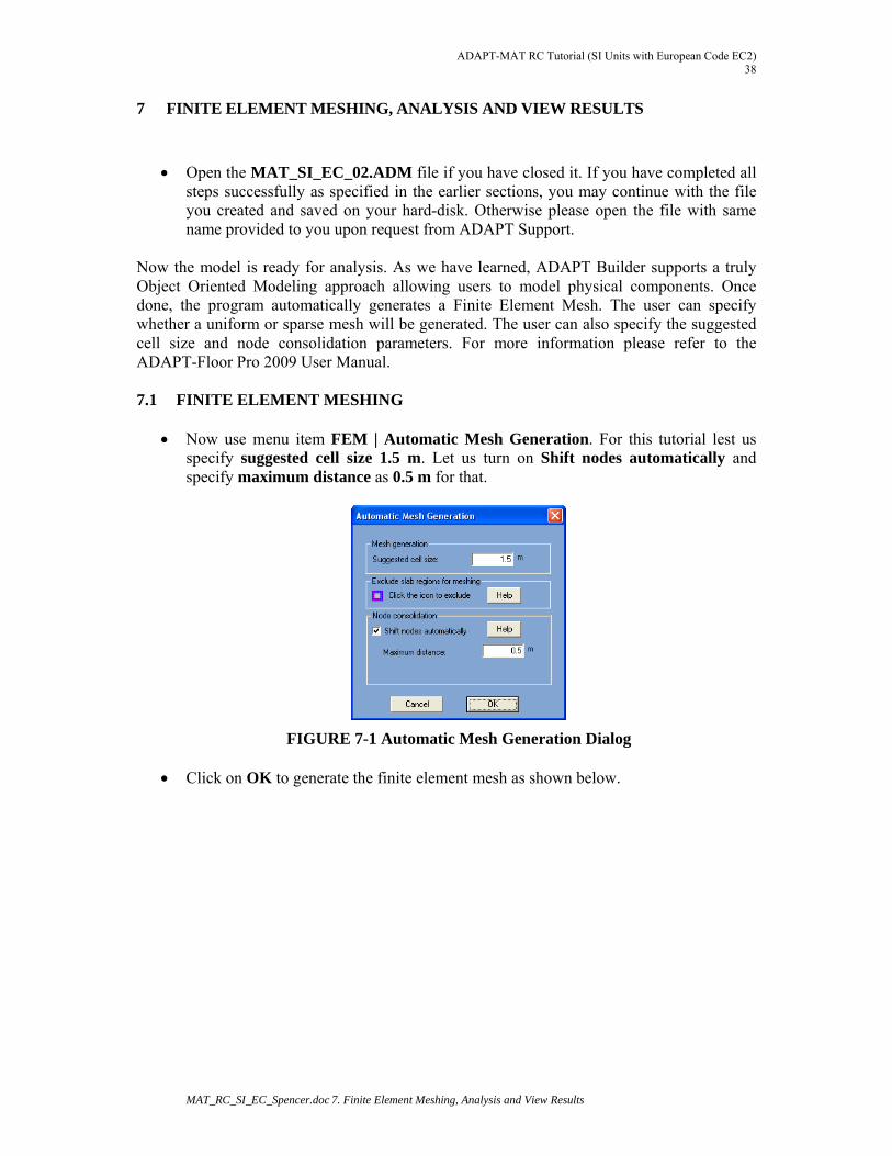
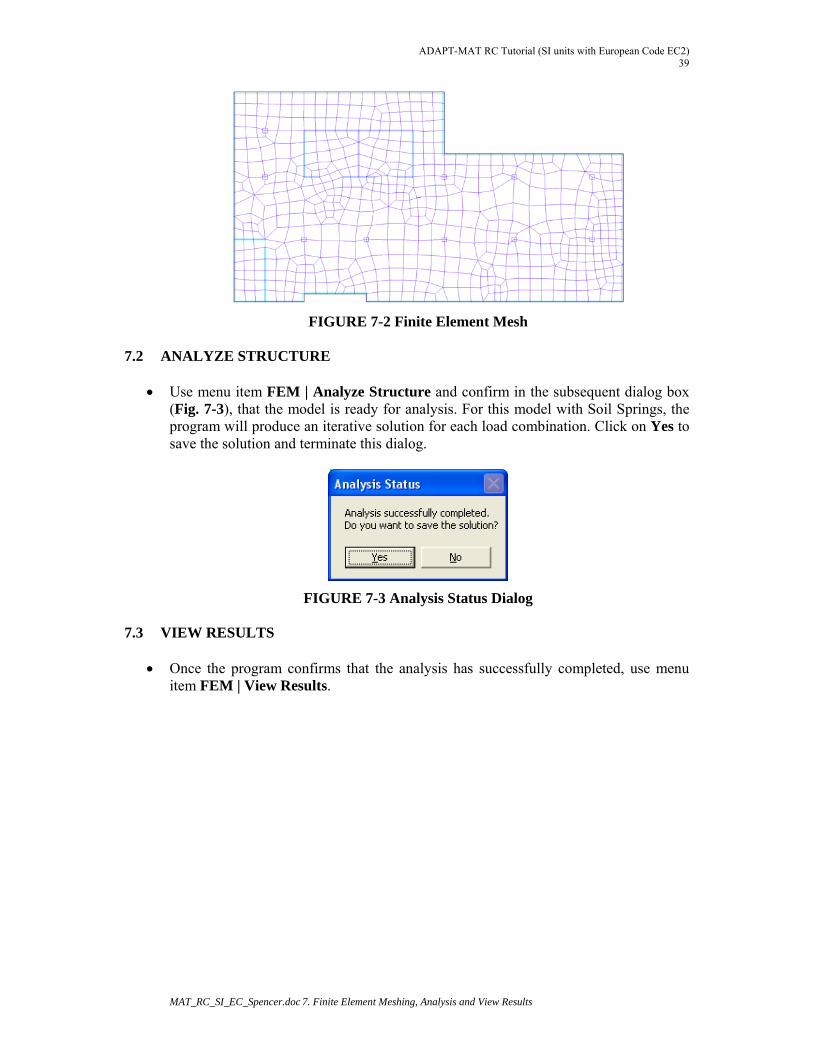
Now use menu item FEM | Automatic Mesh Generation. For this tutorial lest us specify suggested cell size 1.5 m. Let us turn on Shift nodes automatically and specify maximum distance as 0.5 m for that.
FIGURE 7-1 Automatic Mesh Generation Dialog Click on OK to generate the finite element mesh as shown below.
ADAPT-MAT RC Tutorial (SI units with European Code EC2) 39
MAT_RC_SI_EC_Spencer.doc 7. Finite Element Meshing, Analysis and View Results
FIGURE 7-2 Finite Element Mesh
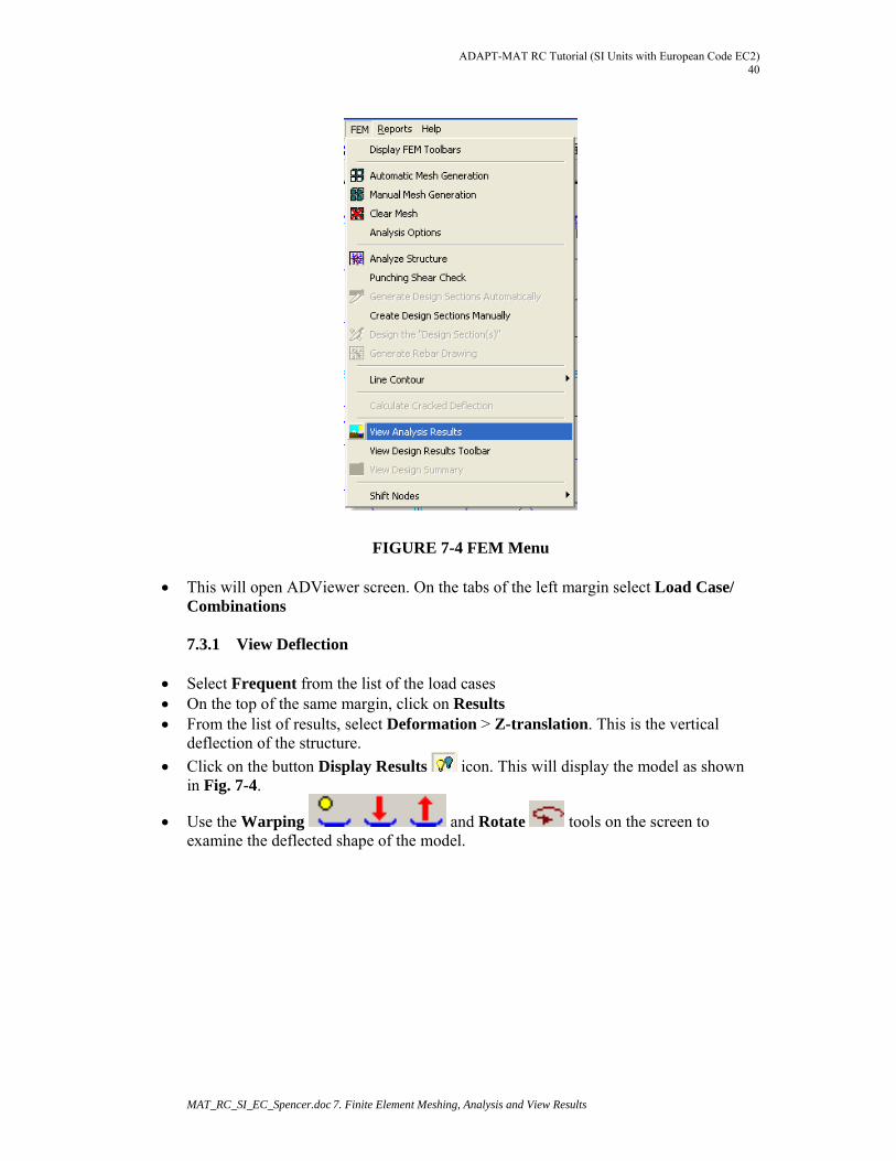
7.2 ANALYZE STRUCTURE Use menu item FEM | Analyze Structure and confirm in the subsequent dialog box
(Fig. 7-3), that the model is ready for analysis. For this model with Soil Springs, the program will produce an iterative solution for each load combination. Click on Yes to save the solution and terminate this dialog.
FIGURE 7-3 Analysis Status Dialog 7.3 VIEW RESULTS
Once the program confirms that the analysis has successfully completed, use menu item FEM | View Results.
ADAPT-MAT RC Tutorial (SI Units with European Code EC2) 40
MAT_RC_SI_EC_Spencer.doc 7. Finite Element Meshing, Analysis and View Results
FIGURE 7-4 FEM Menu
This will open ADViewer screen. On the tabs of the left margin select Load Case/ Combinations
7.3.1 View Deflection
Select Frequent from the list of the load cases On the top of the same margin, click on Results From the list of results, select Deformation > Z-translation. This is the vertical
deflection of the structure.
Click on the button Display Results icon. This will display the model as shown in Fig. 7-4.
Use the Warping and Rotate tools on the screen to examine the deflected shape of the model.
ADAPT-MAT RC Tutorial (SI units with European Code EC2) 41
MAT_RC_SI_EC_Spencer.doc 7. Finite Element Meshing, Analysis and View Results
FIGURE 7-5 Display Screen of FEM Solutions
For further details of the functionality for ADViewer, please refer to the ADAPT-Floor Pro 2009 User Manual. 7.3.2 Review of Soil Pressure
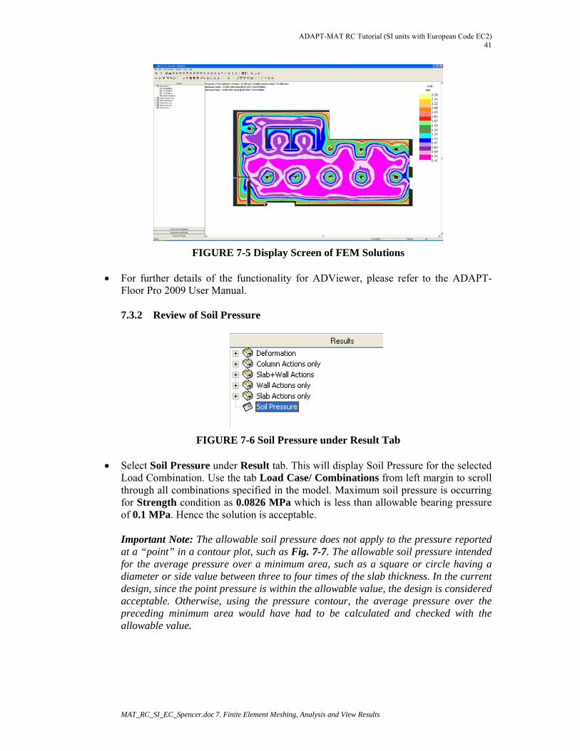
FIGURE 7-6 Soil Pressure under Result Tab Select Soil Pressure under Result tab. This will display Soil Pressure for the selected
Load Combination. Use the tab Load Case/ Combinations from left margin to scroll through all combinations specified in the model. Maximum soil pressure is occurring for Strength condition as 0.0826 MPa which is less than allowable bearing pressure of 0.1 MPa. Hence the solution is acceptable. Important Note: The allowable soil pressure does not apply to the pressure reported at a “point” in a contour plot, such as Fig. 7-7. The allowable soil pressure intended for the average pressure over a minimum area, such as a square or circle having a diameter or side value between three to four times of the slab thickness. In the current design, since the point pressure is within the allowable value, the design is considered acceptable. Otherwise, using the pressure contour, the average pressure over the preceding minimum area would have had to be calculated and checked with the allowable value.
ADAPT-MAT RC Tutorial (SI Units with European Code EC2) 42
MAT_RC_SI_EC_Spencer.doc 7. Finite Element Meshing, Analysis and View Results
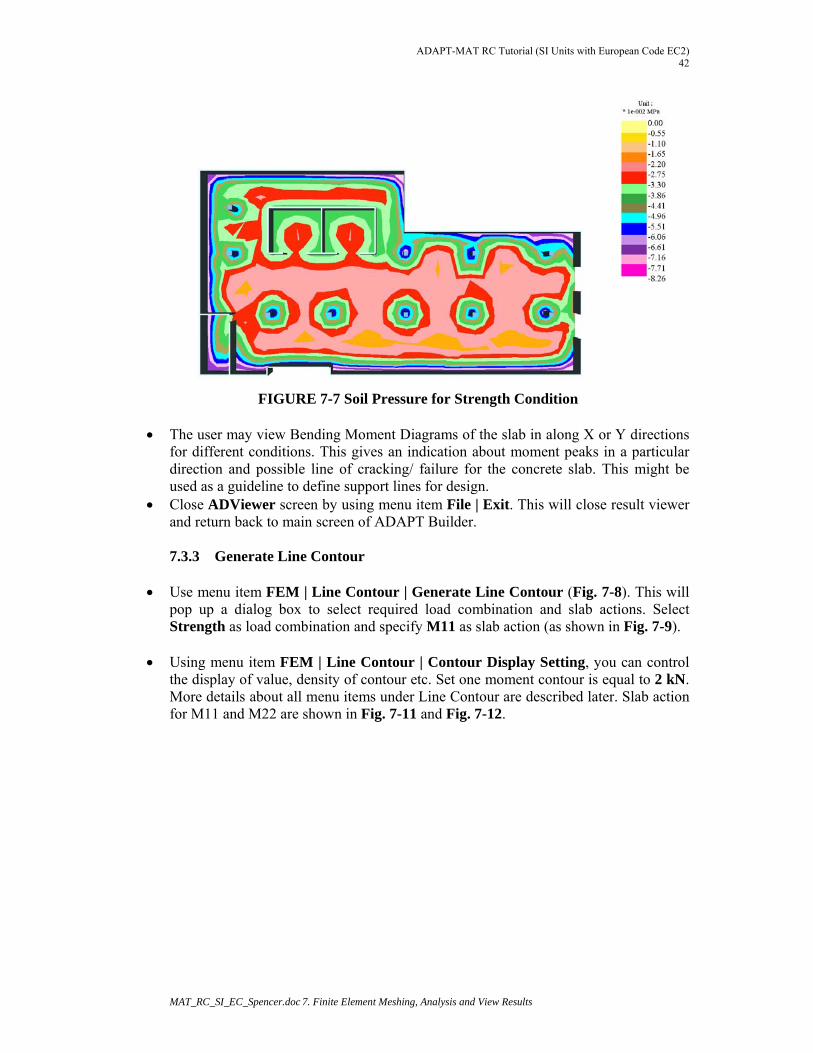
FIGURE 7-7 Soil Pressure for Strength Condition
The user may view Bending Moment Diagrams of the slab in along X or Y directions for different conditions. This gives an indication about moment peaks in a particular direction and possible line of cracking/ failure for the concrete slab. This might be used as a guideline to define support lines for design.
Close ADViewer screen by using menu item File | Exit. This will close result viewer and return back to main screen of ADAPT Builder.
7.3.3 Generate Line Contour
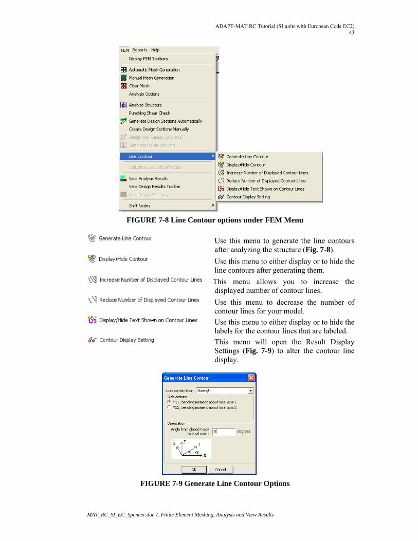
Use menu item FEM | Line Contour | Generate Line Contour (Fig. 7-8). This will
pop up a dialog box to select required load combination and slab actions. Select Strength as load combination and specify M11 as slab action (as shown in Fig. 7-9).
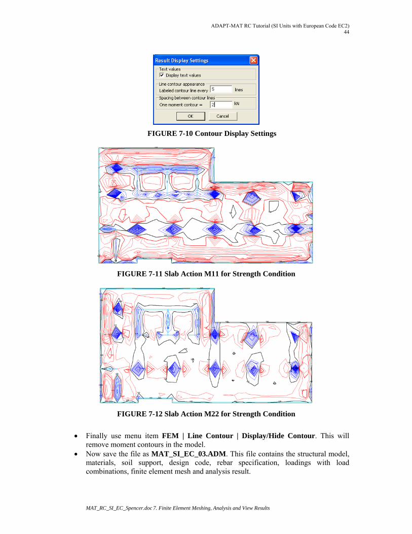
Using menu item FEM | Line Contour | Contour Display Setting, you can control
the display of value, density of contour etc. Set one moment contour is equal to 2 kN. More details about all menu items under Line Contour are described later. Slab action for M11 and M22 are shown in Fig. 7-11 and Fig. 7-12.
ADAPT-MAT RC Tutorial (SI units with European Code EC2) 43
MAT_RC_SI_EC_Spencer.doc 7. Finite Element Meshing, Analysis and View Results
FIGURE 7-8 Line Contour options under FEM Menu
Use this menu to generate the line contours after analyzing the structure (Fig. 7-8).
Use this menu to either display or to hide the line contours after generating them.
This menu allows you to increase the displayed number of contour lines.
Use this menu to decrease the number of contour lines for your model.
Use this menu to either display or to hide the labels for the contour lines that are labeled.
This menu will open the Result Display Settings (Fig. 7-9) to alter the contour line display.
FIGURE 7-9 Generate Line Contour Options
ADAPT-MAT RC Tutorial (SI Units with European Code EC2) 44
MAT_RC_SI_EC_Spencer.doc 7. Finite Element Meshing, Analysis and View Results
FIGURE 7-10 Contour Display Settings
FIGURE 7-11 Slab Action M11 for Strength Condition
FIGURE 7-12 Slab Action M22 for Strength Condition
Finally use menu item FEM | Line Contour | Display/Hide Contour. This will
remove moment contours in the model. Now save the file as MAT_SI_EC_03.ADM. This file contains the structural model,
materials, soil support, design code, rebar specification, loadings with load combinations, finite element mesh and analysis result.
ADAPT-MAT RC Tutorial (SI units with European Code EC2) 45
MAT_RC_SI_EC_Spencer.doc 8. Generation of Support Lines and Use of Splitters
8 GENERATION OF SUPPORT LINES AND USE OF SPLITTERS
Open MAT_SI_EC_03.ADM file if you have closed it. If you have completed all steps successfully as specified in earlier section, you may continue with the file you created and saved in your hard-disk. Otherwise please open the file with same name provided to you upon request from ADAPT Support.
The slab is now ready to be designed. We will first create Support Lines. To establish
proper tributaries, we may need splitters when support lines are not spanning up to the slab boundary. This will allow the program to successfully generate design tributaries. Design sections can then be generated and designed to check the adequacy of the sections as per EC2 requirements. Punching shear requirements will also need to be checked. Finally we will review the results and produce the report.
8.1 GENERATION OF SUPPORT LINES
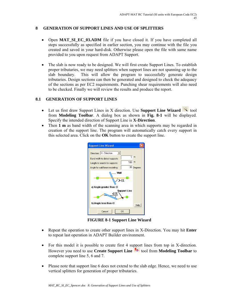
Let us first draw Support Lines in X direction. Use Support Line Wizard tool from Modeling Toolbar. A dialog box as shown in Fig. 8-1 will be displayed. Specify the intended direction of Support Line is X-Direction.
Then 1 m as band width of the scanning area in which supports may be regarded in creation of the support line. The program will automatically catch every support in this selected area. Click on the OK button to create the support line.
FIGURE 8-1 Support Line Wizard
Repeat the operation to create other support lines in X-Direction. You may hit Enter to repeat last operation in ADAPT Builder environment.
For this model it is possible to create first 4 support lines from top in X-direction.
However you need to use Create Support Line tool from Modeling Toolbar to complete support line 5, 6 and 7.
Please note that support line 6 does not extend to the slab edge. Hence, we need to use
vertical splitters for generation of proper tributaries.
ADAPT-MAT RC Tutorial (SI Units with European Code EC2) 46
MAT_RC_SI_EC_Spencer.doc 8. Generation of Support Lines and Use of Splitters
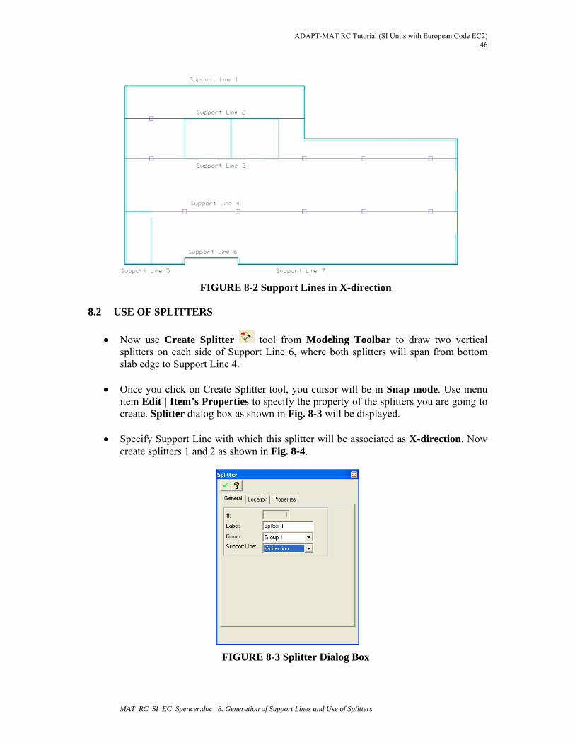
FIGURE 8-2 Support Lines in X-direction 8.2 USE OF SPLITTERS
Now use Create Splitter tool from Modeling Toolbar to draw two vertical splitters on each side of Support Line 6, where both splitters will span from bottom slab edge to Support Line 4.
Once you click on Create Splitter tool, you cursor will be in Snap mode. Use menu
item Edit | Item’s Properties to specify the property of the splitters you are going to create. Splitter dialog box as shown in Fig. 8-3 will be displayed.
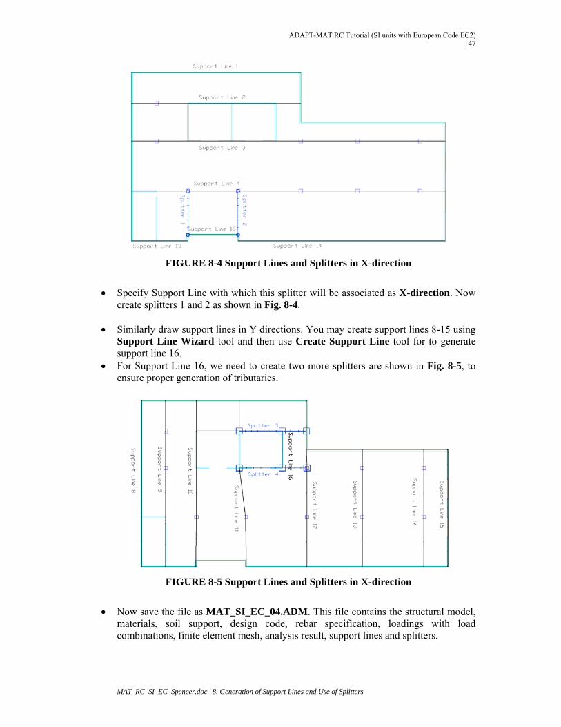
Specify Support Line with which this splitter will be associated as X-direction. Now
create splitters 1 and 2 as shown in Fig. 8-4.
FIGURE 8-3 Splitter Dialog Box
ADAPT-MAT RC Tutorial (SI units with European Code EC2) 47
MAT_RC_SI_EC_Spencer.doc 8. Generation of Support Lines and Use of Splitters
FIGURE 8-4 Support Lines and Splitters in X-direction
Specify Support Line with which this splitter will be associated as X-direction. Now
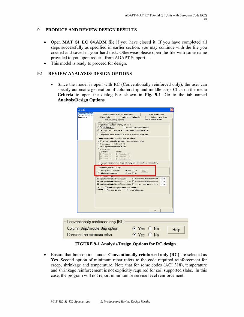
create splitters 1 and 2 as shown in Fig. 8-4. Similarly draw support lines in Y directions. You may create support lines 8-15 using
Support Line Wizard tool and then use Create Support Line tool for to generate support line 16.
For Support Line 16, we need to create two more splitters are shown in Fig. 8-5, to ensure proper generation of tributaries.
FIGURE 8-5 Support Lines and Splitters in X-direction
Now save the file as MAT_SI_EC_04.ADM. This file contains the structural model,
materials, soil support, design code, rebar specification, loadings with load combinations, finite element mesh, analysis result, support lines and splitters.
ADAPT-MAT RC Tutorial (SI Units with European Code EC2) 48
MAT_RC_SI_EC_Spencer.doc 9. Produce and Review Design Results
9 PRODUCE AND REVIEW DESIGN RESULTS
Open MAT_SI_EC_04.ADM file if you have closed it. If you have completed all steps successfully as specified in earlier section, you may continue with the file you created and saved in your hard-disk. Otherwise please open the file with same name provided to you upon request from ADAPT Support. .
This model is ready to proceed for design.
9.1 REVIEW ANALYSIS/ DESIGN OPTIONS
Since the model is open with RC (Conventionally reinforced only), the user can specify automatic generation of column strip and middle strip. Click on the menu Criteria to open the dialog box shown in Fig. 9-1. Go to the tab named Analysis/Design Options.
FIGURE 9-1 Analysis/Design Options for RC design Ensure that both options under Conventionally reinforced only (RC) are selected as
Yes. Second option of minimum rebar refers to the code required reinforcement for creep, shrinkage and temperature. Note that for some codes (ACI 318), temperature and shrinkage reinforcement is not explicitly required for soil supported slabs. In this case, the program will not report minimum or service level reinforcement.

ADAPT-MAT RC Tutorial (SI units with European Code EC2) 49
MAT_RC_SI_EC_Spencer.doc 9. Produce and Review Design Results
Also, for this tutorial we are using the column/middle strip option. This design methodology applies to two-way elevated slabs only and excludes soil supported slabs. This option has been selected for this tutorial to demonstrate how it can be applied in the program. Note that when the column/middle strip option is activated, the program automatically generates these strips. The program DOES NOT allocate reinforcement based on code-prescribed percentages for positive and maximum moment in column and middle strips.
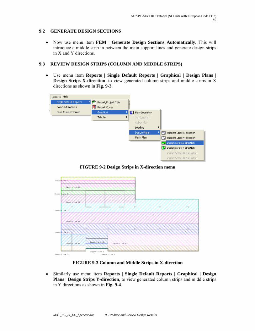
ADAPT-MAT RC Tutorial (SI Units with European Code EC2) 50
MAT_RC_SI_EC_Spencer.doc 9. Produce and Review Design Results
9.2 GENERATE DESIGN SECTIONS
Now use menu item FEM | Generate Design Sections Automatically. This will introduce a middle strip in between the main support lines and generate design strips in X and Y directions.
9.3 REVIEW DESIGN STRIPS (COLUMN AND MIDDLE STRIPS)
Use menu item Reports | Single Default Reports | Graphical | Design Plans | Design Strips X-direction, to view generated column strips and middle strips in X directions as shown in Fig. 9-3.
FIGURE 9-2 Design Strips in X-direction menu
FIGURE 9-3 Column and Middle Strips in X-direction Similarly use menu item Reports | Single Default Reports | Graphical | Design
Plans | Design Strips Y-direction, to view generated column strips and middle strips in Y directions as shown in Fig. 9-4.
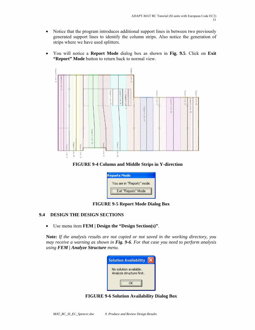
ADAPT-MAT RC Tutorial (SI units with European Code EC2) 51
MAT_RC_SI_EC_Spencer.doc 9. Produce and Review Design Results
Notice that the program introduces additional support lines in between two previously generated support lines to identify the column strips. Also notice the generation of strips where we have used splitters.
You will notice a Report Mode dialog box as shown in Fig. 9.5. Click on Exit
“Report” Mode button to return back to normal view.
FIGURE 9-4 Column and Middle Strips in Y-direction
FIGURE 9-5 Report Mode Dialog Box
9.4 DESIGN THE DESIGN SECTIONS
Use menu item FEM | Design the “Design Section(s)”. Note: If the analysis results are not copied or not saved in the working directory, you may receive a warning as shown in Fig. 9-6. For that case you need to perform analysis using FEM | Analyze Structure menu.
FIGURE 9-6 Solution Availability Dialog Box
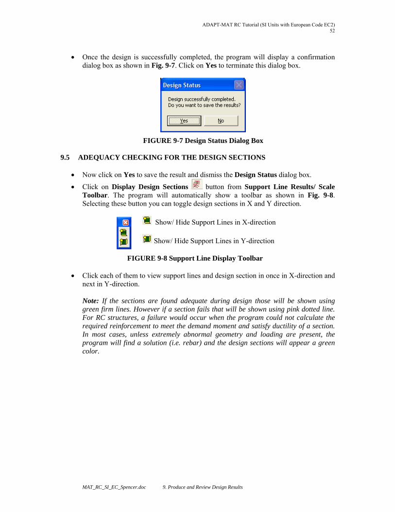
ADAPT-MAT RC Tutorial (SI Units with European Code EC2) 52
MAT_RC_SI_EC_Spencer.doc 9. Produce and Review Design Results
Once the design is successfully completed, the program will display a confirmation
dialog box as shown in Fig. 9-7. Click on Yes to terminate this dialog box.
FIGURE 9-7 Design Status Dialog Box
9.5 ADEQUACY CHECKING FOR THE DESIGN SECTIONS
Now click on Yes to save the result and dismiss the Design Status dialog box.
Click on Display Design Sections button from Support Line Results/ Scale Toolbar. The program will automatically show a toolbar as shown in Fig. 9-8. Selecting these button you can toggle design sections in X and Y direction.
Show/ Hide Support Lines in X-direction
Show/ Hide Support Lines in Y-direction
FIGURE 9-8 Support Line Display Toolbar Click each of them to view support lines and design section in once in X-direction and
next in Y-direction.
Note: If the sections are found adequate during design those will be shown using green firm lines. However if a section fails that will be shown using pink dotted line. For RC structures, a failure would occur when the program could not calculate the required reinforcement to meet the demand moment and satisfy ductility of a section. In most cases, unless extremely abnormal geometry and loading are present, the program will find a solution (i.e. rebar) and the design sections will appear a green color.
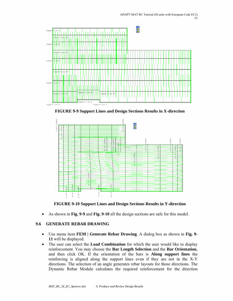
ADAPT-MAT RC Tutorial (SI units with European Code EC2) 53
MAT_RC_SI_EC_Spencer.doc 9. Produce and Review Design Results
FIGURE 9-9 Support Lines and Design Sections Results in X-direction
FIGURE 9-10 Support Lines and Design Sections Results in Y-direction As shown in Fig. 9-9 and Fig. 9-10 all the design sections are safe for this model.
9.6 GENERATE REBAR DRAWING
Use menu item FEM | Generate Rebar Drawing. A dialog box as shown in Fig. 9-11 will be displayed.
The user can select the Load Combination for which the user would like to display reinforcement. You may choose the Bar Length Selection and the Bar Orientation, and then click OK. If the orientation of the bars is Along support lines the reinforcing is aligned along the support lines even if they are not in the X-Y directions. The selection of an angle generates rebar layouts for those directions. The Dynamic Rebar Module calculates the required reinforcement for the direction
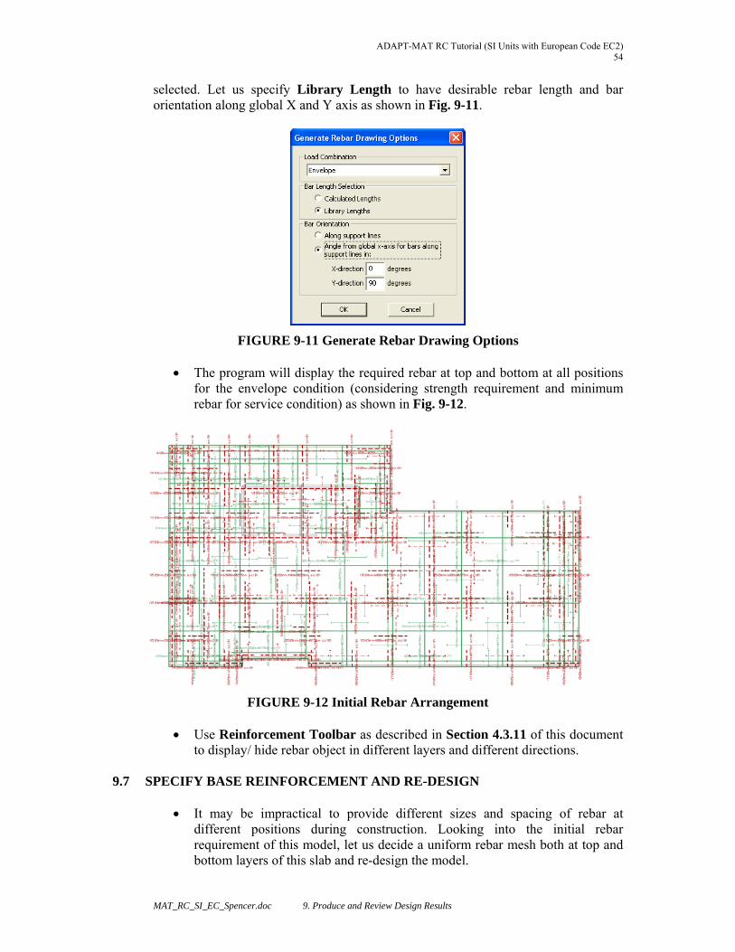
ADAPT-MAT RC Tutorial (SI Units with European Code EC2) 54
MAT_RC_SI_EC_Spencer.doc 9. Produce and Review Design Results
selected. Let us specify Library Length to have desirable rebar length and bar orientation along global X and Y axis as shown in Fig. 9-11.
FIGURE 9-11 Generate Rebar Drawing Options
The program will display the required rebar at top and bottom at all positions for the envelope condition (considering strength requirement and minimum rebar for service condition) as shown in Fig. 9-12.
FIGURE 9-12 Initial Rebar Arrangement
Use Reinforcement Toolbar as described in Section 4.3.11 of this document to display/ hide rebar object in different layers and different directions.
9.7 SPECIFY BASE REINFORCEMENT AND RE-DESIGN
It may be impractical to provide different sizes and spacing of rebar at
different positions during construction. Looking into the initial rebar requirement of this model, let us decide a uniform rebar mesh both at top and bottom layers of this slab and re-design the model.
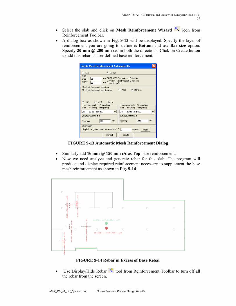
ADAPT-MAT RC Tutorial (SI units with European Code EC2) 55
MAT_RC_SI_EC_Spencer.doc 9. Produce and Review Design Results
Select the slab and click on Mesh Reinforcement Wizard icon from Reinforcement Toolbar.
A dialog box as shown in Fig. 9-13 will be displayed. Specify the layer of reinforcement you are going to define is Bottom and use Bar size option. Specify 20 mm @ 200 mm c/c in both the directions. Click on Create button to add this rebar as user defined base reinforcement.
FIGURE 9-13 Automatic Mesh Reinforcement Dialog
Similarly add 16 mm @ 150 mm c/c as Top base reinforcement. Now we need analyze and generate rebar for this slab. The program will
produce and display required reinforcement necessary to supplement the base mesh reinforcement as shown in Fig. 9-14.
FIGURE 9-14 Rebar in Excess of Base Rebar
Use Display/Hide Rebar tool from Reinforcement Toolbar to turn off all the rebar from the screen.
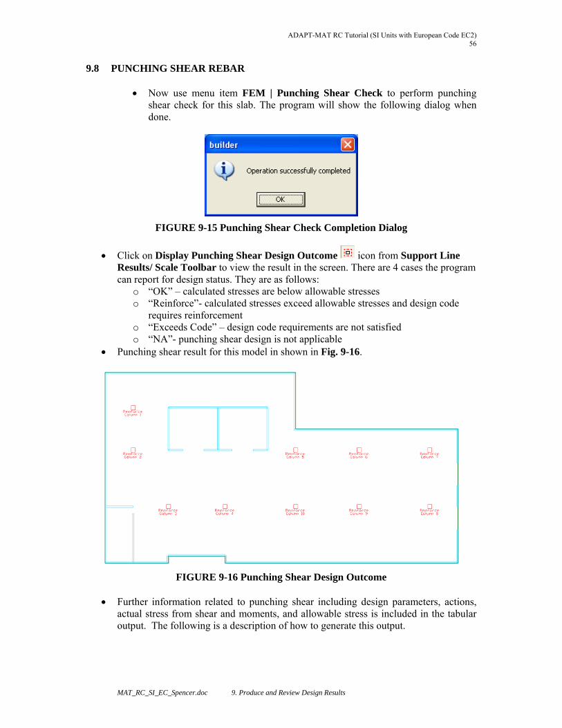
ADAPT-MAT RC Tutorial (SI Units with European Code EC2) 56
MAT_RC_SI_EC_Spencer.doc 9. Produce and Review Design Results
9.8 PUNCHING SHEAR REBAR Now use menu item FEM | Punching Shear Check to perform punching
shear check for this slab. The program will show the following dialog when done.
FIGURE 9-15 Punching Shear Check Completion Dialog
Click on Display Punching Shear Design Outcome icon from Support Line Results/ Scale Toolbar to view the result in the screen. There are 4 cases the program can report for design status. They are as follows:
o “OK” – calculated stresses are below allowable stresses o “Reinforce”- calculated stresses exceed allowable stresses and design code
requires reinforcement o “Exceeds Code” – design code requirements are not satisfied o “NA”- punching shear design is not applicable
Punching shear result for this model in shown in Fig. 9-16.
FIGURE 9-16 Punching Shear Design Outcome
Further information related to punching shear including design parameters, actions, actual stress from shear and moments, and allowable stress is included in the tabular output. The following is a description of how to generate this output.
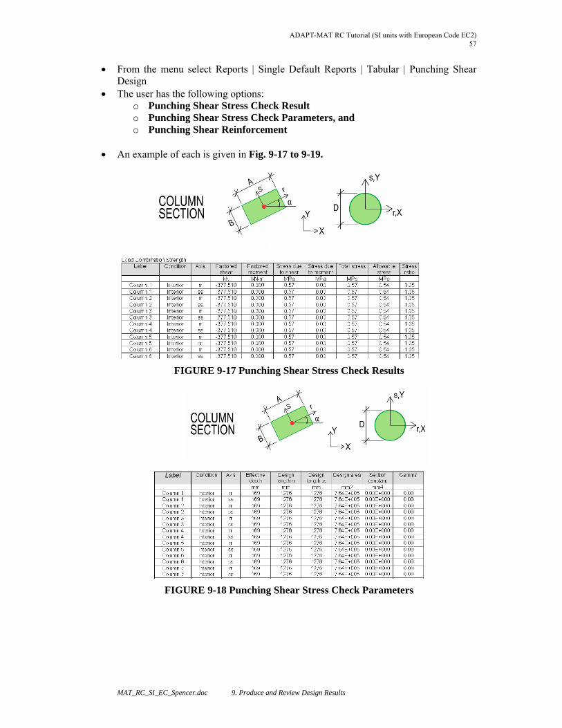
ADAPT-MAT RC Tutorial (SI units with European Code EC2) 57
MAT_RC_SI_EC_Spencer.doc 9. Produce and Review Design Results
From the menu select Reports | Single Default Reports | Tabular | Punching Shear Design
The user has the following options: o Punching Shear Stress Check Result o Punching Shear Stress Check Parameters, and o Punching Shear Reinforcement
An example of each is given in Fig. 9-17 to 9-19.
FIGURE 9-17 Punching Shear Stress Check Results
FIGURE 9-18 Punching Shear Stress Check Parameters

ADAPT-MAT RC Tutorial (SI Units with European Code EC2) 58
MAT_RC_SI_EC_Spencer.doc 9. Produce and Review Design Results
FIGURE 9-19 Punching Shear Reinforcement


