Page 1
Restricted © Siemens AG 2014. All rights reserved
Energiekonzepte der ZukunftSpeichersysteme
Siemens Corporate Technology | June 2014
Dr. Dieter Most
Ringvorlesung „Transformation des Energiesystems“ – Leibnitz Universität Hannover
Page 2
Unrestricted. © Siemens AG 2014. All rights reserved.Page 2 June 2014 Corporate Technology
Table of contents
Siemens AG – Corporate Technology
Short Overview Activities of the Research Group Energy Storage
Vortrag Energiekonzepte der Zukunft -Speichersysteme
Energiewende
Energy Storage – Use Case
Energy Storage – Types
Page 3
Unrestricted. © Siemens AG 2014. All rights reserved.Page 3 June 2014 Corporate Technology
Siemens is organized in 4 Sectors: Industry, Energy, Healthcare and Infrastructure & Cities
Siemens: Facts and Figures
1) Sales in FY 2013
Siemens sectors
• Sales: ~€ 76 bn.
• Locations: In 190countries
• Employees: ~362,000
• R&Dexpenses: ~€ 4.3 bn.
• R&Dengineers: ~29,800
• Inventions: ~8,400
• Active patents: ~60,000
Key figures FY 2013
Divisions:• Industry
Automation• Drive
Technologies• Customer
Services
Divisions:• Power
Generation• Wind Power• Energy Service• Power
Transmission
Divisions:• Imaging &
Therapy Systems• Clinical Products• Diagnostics• Customer
Solutions
Divisions:• Rail Systems• Mobility & Logistics• Low and Medium
Voltage• Smart Grid• Building
Technologies
Corporate functions
Corporate TechnologyCorp. Finance
…
Corp. TechnologyCorp. Development
Infrastructure& CitiesHealthcareEnergyIndustry
~€ 14 bn.1) ~€ 18 bn.1)~€ 19 bn.1) ~€ 27 bn.1)
Page 4
Unrestricted. © Siemens AG 2014. All rights reserved.Page 4 June 2014 Corporate Technology
Siemens AGNeue Organisationsstruktur ab 1.10.2014
Page 5
Unrestricted. © Siemens AG 2014. All rights reserved.Page 5 June 2014 Corporate Technology
CT is headed by the Siemens CTO, Klaus Helmrich
CT organization (as of April 1, 2014)
Corporate Technology (CT)CTO: Klaus Helmrich (ab 1.10. Siegfried Russwurm)
Centralfunctions
Jörg Bischoff
Chief Financial Officer (CFO)
Gunter Erb
Human Resources
1) Sector and Division CTOs are employees of the Sectors also reporting to the Siemens CTO. They advise the CTO through the WGI
Special responsibilities• Export Control and Customs
• Quality Management
• PM@Siemens
• Risk and Internal Control
• Dangerous Goods
• Environmental Health and Safety
• Legal
• Information Technology
• Information Security
• Compliance
Regions
(R)
Wolfgang Heuring
Innovative Ventures
(IV)
Rudolf Freytag
Research& Tech-nologyCenter
(RTC)
Wolfgang Heuring
Develop-mentCenter
(DC)
Gerd Hoefner
Intellectual Property
(IP)
Beate Weibel
New Technology Fields
(NTF)
Armin Schnettler
Business Excellence
(BE)
Katharina Beumelburg
Working GroupInno-vation1)
(WGI)
Klaus Helmrich
Technology & Innova-tion Mana-gement
(TIM)
NorbertLütke-Entrup
Page 6
Unrestricted. © Siemens AG 2014. All rights reserved.Page 6 June 2014 Corporate Technology
CT has a global presence to ensure proximity tointernal clients and pockets of excellence worldwide
Global organization of CT (major locations)
<100 People
100 500 People
>500 People
Country with CT site
PrincetonBerkeley Beijing
Shanghai
Kolkata
Moscow
Tokyo
St. Petersburg
Bangalore
Pune
Berlin
Erlangen
Munich
Vienna
BratislavaKosice
Brasov
Brno
Ankara
Praha
Gebze
Page 7
Unrestricted. © Siemens AG 2014. All rights reserved.Page 7 June 2014 Corporate Technology
CT Research and Technology Center:~1,600 experts in 12 technology fields
1) Headquarter 2) Research Groups 3) from January 1st, 2014
CT Research and Technology Center (RTC)
Materials
IT Security
• Innovative materials and coatings
• Advanced manufacturing technologies
• Analytics
HQ: BerlinRGs: 8
• Security architecture & lifecycle
• CERT services• Embedded security
HQ: MunichRGs: 8
Sensor Tech-nologies
Automation & Control
• Sensor devices & system integration
• Inspection & test
HQ: ErlangenRGs: 8
• Modeling & simulation• Engineering• Runtime &
optimization• Solutions
HQ: Princeton, USRGs: 12
Power & Energy Technologies
Networks & Communication
• Power management• Switching• Power electronics• Energy storage• Electromagnetic
systems & mechatronics
• Energy & industrial processes
HQ: ErlangenRGs: 12
• Wireless & industrial networks
• Internet of things
HQ: MunichRGs: 6
IT Platforms
• Image reconstruction and visualization
• Computer vision• Image processing &
video analytics• Cardiovascular, onco
and neuro imaging• Interventional imaging• Computational imaging
HQ: Princeton, USRGs: 13
• SW / System integration
• Middleware, cloud• Enterprise IT
HQ: MunichRGs: 10
Software Architecture Development
Systems Engineering
• Software architecture• Software test and
system qualities• Development
efficiency• Product lines and SW
Ecosystems
HQ 1): MunichRGs 2): 8
• Usability design• Engineering• Reliability• Manufacturing
solutions• Process support
HQ: MunichRGs: 12
Business Analytics & Monitoring
• Electronic design & processing
• Radio frequency solutions
• Integrated technologies
• Manufacturing technologies
HQ: MunichRGs: 8
• Decision support• Knowledge discovery• Condition monitoring
HQ: MunichRGs: 9
Electronics
3)
Imaging & Computer Vision
Page 8
Unrestricted. © Siemens AG 2014. All rights reserved.Page 8 June 2014 Corporate Technology
Li-IonBattery
Pb-AcidBattery
Redox FlowBattery
Siemens CT RTC – Research Group Energy StorageBatteries and DLCs – Activities (1)
Mobile Storage Conceptse-storage definition, technology selection and verification
Energy recovery for mobilitysafety concepts, failure analysisbenchmark of companies & products
kWh Storage Solutionbenchmark of suppliers & technology, feasibility studies, optimized operation strategy, system concepts, prototypes
Storage Concepts for Smart Grids(micro and industrial grids) grid integration, modeling, optimized operation strategy
Hybrid ConceptSitras HES + MES
Storage for Small Off-Grid Solutionsfeasibility studies, concept and HW development, prototype
Non visible contact line (NVC)
SWARMCentral Control
…
PV Internet
BatteryConsumer
PV
BatteryConsumer
BatteryComsumer
PV
virtual storage plantGrid
Stationary MWh Storage Solutionmarket survey, feasibility studies, system concepts; HW development, prototype; operation strategy
SWARM Concepts – VSP~120 residential storage á 18kW add up to a 2MW virtual storage plant
NaNiCl2Battery
VSP: Virtual Storage Power Plant
Osram - Lake Victoria Project
Page 9
Unrestricted. © Siemens AG 2014. All rights reserved.Page 9 June 2014 Corporate Technology
Siemens CT RTC – Research Group Energy Storage Batteries and DLCs – Activities (2)
Battery Integration HEV / EV / eAircraftdemonstrator, battery selection and qualification, model development
Battery Modelingmodel development & verification (Matlab-Simulink)
SVC Plus + Energy Storagebenchmark of suppliers & products, Supercap characterization, FMEA
DLC & Battery Qualification (Li-Ion, Pb-Acid, NaNiCl2, Redox-Flow, Supercaps, Hybridcaps)market survey, benchmark of suppliers & products, battery characterization, failure analysis
DLC for Starters (Heavy Rail) and Steering Assistancequalification of double-layer capacitors, failure analysis
Cells for Hearing Aids, Sensors & Consumer Electronics benchmark of suppliers & products, battery characterization, failure analysis
Post-mortem analysisStarter Heavy Rail
DLC: Double layer capacitor, e.g. ultracapsHEV: Hybrid Electric vehicle, EV: (Full) Electric vehicle
Operational ModelOperational ModelOperational Model Monitoring
max
min
SOC, T_Cell, U_Cell, …
Page 10
Unrestricted. © Siemens AG 2014. All rights reserved.Page 10 June 2014 Corporate Technology
Siemens AG – Corporate Technology
Short Overview Activities of the Research Group Energy Storage
Energiekonzepte der Zukunft Speichersysteme
Energiewende
Energy Storage – Use Case
Energy Storage – Types
Page 11
Unrestricted. © Siemens AG 2014. All rights reserved.Page 11 June 2014 Corporate Technology
Germany’s “Energiewende”- Good or Bad Move? -
Page 12
Unrestricted. © Siemens AG 2014. All rights reserved.Page 12 June 2014 Corporate Technology
„Energiewende“ takes up speed and gets globalGermany lost its frontrunner position
.. UK PV-Einspeisetarif von 14,4 €Ct/kWh in 2015, der dann bis 12,0 €Ct/kWh in 2019 absinkt .... UK PV-Einspeisetarif von 14,4 €Ct/kWh in 2015, der dann bis 12,0 €Ct/kWh in 2019 absinkt .... UK PV-Einspeisetarif von 14,4 €Ct/kWh in 2015, der dann bis 12,0 €Ct/kWh in 2019 absinkt ..
Page 13
Unrestricted. © Siemens AG 2014. All rights reserved.Page 13 June 2014 Corporate Technology
Energiewende
Wo geht die Reise hin ?
Page 14
Unrestricted. © Siemens AG 2014. All rights reserved.Page 14 June 2014 Corporate Technology
Entwicklung StromgestehungskostenErneuerbare Energien & Fossile Erzeugung
Source FhG ISE 2013 – Studie STROMGESTEHUNGSKOSTEN ERNEUERBARE ENERGIEN
Biogas
Wind Offshore
Photovoltaik
Wind Onshore
GuDSteinkohle
Braunkohle
Renewable Fossile
Page 15
Unrestricted. © Siemens AG 2014. All rights reserved.Page 15 June 2014 Corporate Technology
Forecast Installed Capacity Photovoltaic and Wind- Global -
Photovoltaic- Forecast -
Wind- Forecast -
Solar Power, Wind, Biomass- History -
Page 16
Unrestricted. © Siemens AG 2014. All rights reserved.Page 16 June 2014 Corporate Technology
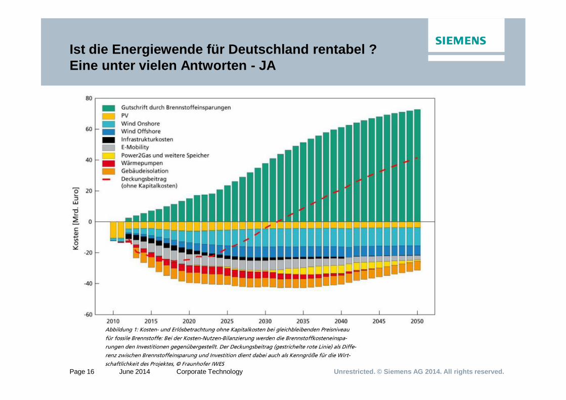
Ist die Energiewende für Deutschland rentabel ?Eine unter vielen Antworten - JA
Page 17
Unrestricted. © Siemens AG 2014. All rights reserved.Page 17 June 2014 Corporate Technology
Storage is the holy grail of the power industry- all media talk about it!
Page 18
Unrestricted. © Siemens AG 2014. All rights reserved.Page 18 June 2014 Corporate Technology
Installed Base and Energy DemandGermany – Exemplary Scenario 2011
Source: O. Bitter, U. Lenk, I. Pyc, Auswirkungen der globalen Finanz- und Wirtschaftskrise auf den Kraftwerksanlagenbau, 41. KWT Dresden 2009; Uwe Lenk (Siemens E F NT ES), June 2011
Outlook Energy Demand Outlook Installed Power
max 77GWDemand GER `10
min 34GW
110 GWpeak
Exemplary Scenario
Page 19
Unrestricted. © Siemens AG 2014. All rights reserved.Page 19 June 2014 Corporate Technology
In an “80% renewable world” storage is an important part of power architecture
Situation today and in future
Energy storage is an important lever to meet those challenges
Source: Bundesverband WindEnergie, EEG, Team Thermal Storage, Source E ST MC
Key facts and assumptionsRenewable energy is a fluctuating energy source, not continuously available, not dispatchable
Challenges today
Germany 20101: up to 150 GWh of potential wind production curtailed due to overload
United States TX 2009: 17% of potential wind production curtailed due to overload
Will increase in future
24.000 GWh excess energy expected for germany in 20302
EU target for 2050: 80% share of renewables within power supply
1 – 9% generation (26% installed base) out of volatile renewable2 - 31% generation (54% installed base) out of volatile renewable, maximal grid extension assumed (“copperplate assumption”)
Smart Grid
Grid extension
Energy storage
Flexible conventional
energy generation
Page 20
Unrestricted. © Siemens AG 2014. All rights reserved.Page 20 June 2014 Corporate Technology
Enegiewende and Storage- Big Questions -
What amount of storage do we need ?
What amount of storage do we get ?
And what kind of storage technology do we need ?
What types of storage do we get ?
Page 21
Unrestricted. © Siemens AG 2014. All rights reserved.Page 21 June 2014 Corporate Technology
Economic Feasible Business Cases forEnergy Storage
Page 22
Unrestricted. © Siemens AG 2014. All rights reserved.Page 22 June 2014 Corporate Technology
Where will Energy Storage be installed
Early installations of ESS in 2012 and 2013 have occurred primarily in Germany, the United States and Japan. From 2012 to 2016, the Americas is forecast to be the largest major region in terms of MW of ESS installed.
In-the-grid is forecast to be the largest of the inter-connection locations in 2022 in terms of ESS power installed. Second is Behind-the-meter.
Page 23
Unrestricted. © Siemens AG 2014. All rights reserved.Page 23 June 2014 Corporate Technology
Market Development Energy StorageForecast - Global -
Source: BCG PV+Storage 2013
Page 24
Unrestricted. © Siemens AG 2014. All rights reserved.Page 24 June 2014 Corporate Technology
Table of contents
Siemens AG – Corporate Technology
Short Overview Activities of the Research Group Energy Storage
Energiekonzepte der Zukunft Speichersysteme
Energiewende
Energy Storage – Use Case
Energy Storage – Types
Page 25
Unrestricted. © Siemens AG 2014. All rights reserved.Page 25 June 2014 Corporate Technology
New Applications for Energy Storage
Renewable Power
Conventional PowerGrid - Installed Base
Smart Grids Energy Efficient Cities
Key technology to an efficient future power generation with high share of Renewables
Energy Storage
Page 26
Unrestricted. © Siemens AG 2014. All rights reserved.Page 26 June 2014 Corporate Technology
Available storage technologies cover different requirements to power and capacity
Mechanical Storage
Electrochemical Storage
Electrical Storage
Chemical Storage
Thermal Storage
CAES: Compressed Air Energy StorageSMES: Super-Magnetic Energy StorageSNG: Synthetic Natural GasH2: Hydrogen (Electrolysis)PH: Pumped HydroHEV: Hybrid Electric Vehicle
Min
utes
Seco
nds
Hou
rsD
ays
1 kW 10 kW 100 kW 1 MW 10 MW 100 MW 1.000 MW
Batteries
Flywheelstorage
Ultracapacitor
SMES
Redox-Flow-Batteries
H2 Power to Gas Power to Liquid
PumpedHydro
CAES
Power to Heat (to Power)
Power Quality1
Time Shift3
Energy Reserve
Operating Reserve2
4
WindTurbine
Windoff-shore
MediumPV FarmeCar
Light-weight Train
Li-Ion
NaSNaNiClLead Acid
Power to Heat
HEV
Page 27
Unrestricted. © Siemens AG 2014. All rights reserved.Page 27 June 2014 Corporate Technology
Decentra-lized Fleet
Min
utes
Seco
nds
Hou
rsD
ays
Wee
ks
< 10 kW > 1,000 MW
Power qualityA
Energy reserveD
FirmingB
TimeshiftC
Different energy storage technologies fit to varying requirements of stationary use cases
Distribution Grid
Transmission Grid
Energy Reserve (Electricity)
Volatile Power Plants
ConventionalPower Plants
Central Fleet
1
4 2
2b 2c 2d
33b
Application Segmentation
• Cover low wind or sun periods
Power
Energy Reserve
Con-/ Prosumer Generation
2a
3aGrid
• Self supply/peak shaving industrial
• Self supplyresidential
• Shift energy• Integrate
Renewable
• Participate in regular market
• Comply withgrid require-ments
• Enhance Flexibility
• Offer district heat
• Shift energy• Provide
balancing energy
• Ensure powerquality
• Ensure powerquality
Match of Storage Technology w/ UC (excerpt of electrochemical types)
Page 28
Unrestricted. © Siemens AG 2014. All rights reserved.Page 28 June 2014 Corporate Technology
Siemens AG – Corporate Technology
Short Overview Activities of the Research Group Energy Storage
Energiekonzepte der Zukunft Speichersysteme
Energiewende
Energy Storage – Use Case
Energy Storage – Types
Page 29
Unrestricted. © Siemens AG 2014. All rights reserved.Page 29 June 2014 Corporate Technology
Vergleich von Energiedichten
Energiespeicher 56 kWh
150 kWh
10.000kWh
90C – 60Cthermisch
Modul elektrisch
Heizwertthermisch
Page 30
Unrestricted. © Siemens AG 2014. All rights reserved.Page 30 June 2014 Corporate Technology
Vergleich von Energiedichten
Mechanische Speicher (sehr geringe Energiedichte)• Potentielle Energie (z.B. Pumpspeichersee): 1 kWh/m³ (bei 360 m Höhe)• Kinetische Energie (z.B. Schwungrad): ~10 kWh/m³
Elektrische Speicher (geringe Energiedichte)• Elektrostatisches Feld: ~10 kWh/m³• Elektromagnetisches Feld: ~10 kWh/m³
Wärmespeicher (mittlere Energiedichte)• Wasser @ T = 100K: 116 kWh/m³ (sensible Wärme) • Phasenwechsel, z.B. H2O/ Dampf: 626 kWh/m³ (latente Wärme)
Chemische Speicher (mittlere bis hohe Energiedichte)• Lithium-Ionen-Batterie: 110 - 200 kWh/m³• Flüssiger Wasserstoff: 2.400 kWh/m³
• Heizöl 10.000 kWh/m³• Benzin: 12.000 kWh/m³
Source: Siemens, Sauer RWTH Aachen
Page 31
Unrestricted. © Siemens AG 2014. All rights reserved.Page 31 June 2014 Corporate Technology
Which storage / battery technologies are available?
Page 32
Unrestricted. © Siemens AG 2014. All rights reserved.Page 32 June 2014 Corporate Technology
Energy Storage Systems - New technologies are emerging; costs decreasing with mass production
Page 33
Unrestricted. © Siemens AG 2014. All rights reserved.Page 33 June 2014 Corporate Technology
Classic Technology Lead Acid Battery
Lead-Acid 25-30 Wh/kgBrutto: Pb + PbO2 + 2H2SO4 2PbSO4 + 2H2O 2.047V
Pos. Electrode: bO2 + HSO4- + 3H+ + 2e- PbSO4 + 2H2O
Neg. Electrode: Pb + HSO4- PbSO4 + H+ + 2e-
Pro: Approved Technology• Robuste & dheap• Simple to implementCon:• Issues when deep discharged• Cyclic life time too low
Page 34
Unrestricted. © Siemens AG 2014. All rights reserved.Page 34 June 2014 Corporate Technology
Classic Technology Lead Acid Battery – Historical Application
Page 35
Unrestricted. © Siemens AG 2014. All rights reserved.Page 35 June 2014 Corporate Technology
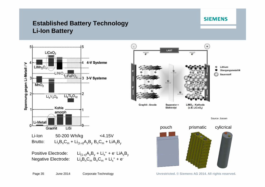
Established Battery TechnologyLi-Ion Battery
Li-Ion 50-200 Wh/kg <4.15VBrutto: LixBnCm + Li(1-x)AzBy BnCm + LiAzBy
Positive Electrode: Li(1-x)AzBy + Lix+ + e- LiAzByNegative Electrode: LixBnCm BnCm + Lix+ + e-
Source Jossen
pouch prismatic cylicrical
Page 36
Unrestricted. © Siemens AG 2014. All rights reserved.Page 36 June 2014 Corporate Technology
pouch prismatic cylicrical
Li-Ion: Safety• Issues if operated at over
temperature (typically >45Deg. C) • Iissues if over- or deep discharged
Battery Management System (BMS) for permanet monitoring ofcell temperatures, cell voltage andstate of charge necessary.BMS enables safe disconnection of the DC-String and power electronics, too
+ BMS
Established Battery TechnologyLi-Ion Battery
Page 37
Unrestricted. © Siemens AG 2014. All rights reserved.Page 37 June 2014 Corporate Technology
Battery BasicsCharge / Discharge Characteristics
IU Charging Method
• Constant Current ChargingVoltage will decrease during charging process
• Constant Voltage ChargingCurrent will decrease till the end of the charging process
• DischargingVoltage will decrease with discharging
• Lead Acid chargingadditional parasitic processes (at end of charging process)Negative: H2-Production & lower efficiencyPositive: can be used for balancing
of
Power electronics must be compatible to voltage and current bandwitdh of
the battery
Page 38
Unrestricted. © Siemens AG 2014. All rights reserved.Page 38 June 2014 Corporate Technology
Battery Basics Capacity dependent on discharge rate
Page 39
Unrestricted. © Siemens AG 2014. All rights reserved.Page 39 June 2014 Corporate Technology
Battery Basics Lifetime – Capacity decreases; Ri increases with time
Typical development of residual capacity, internal resistance and ferquency of interventions of SAP
100% C/C0
70% C/C0
80% C/C0
200% Ri/Ri0
100% Ri/Ri0
end of life criteria - capacity
end of life criteria – internal resistance
Interventions of Soft Asset Protectionincreased frequency of SAP interventions may occur near the end of life due to lower residual performance
Time [years]
Decrease of capacity / increase of internal Resistancy Ri dependent on• Time idling as f(SOC, T) – calendaric aging• Charge/discharge rate as f(T, avg. SOC) – cyclic aging• Cycle depth and number as f(T, avg. SOC) – cyclic aging
End-of-life criteria• 80% resp. 70% of Capacity C0• 150 % resp. 200% of Ri,0
Page 40
Unrestricted. © Siemens AG 2014. All rights reserved.Page 40 June 2014 Corporate Technology
Large anticipated price decrease of batteries will produce many positive business cases by 2020
Source IHS (EER / Isupply / IMS research) 2013
By 2020 all battery technologies with target price benchmark of 200-300$/kWh per cell pack
This converts to system prices of 600 to 1000$/kWh (if components like inverters and other BoPcontribute to price decrease)
Today 1400 – 2500 $ / kWh
With these price levels many use-cases of decentral application will become viable
Battery prices for PV storage (US$/kWh)
Li-Ion has a minimum cost boundary at ~ 200$/kWh on cell and ~ 400$/kWh on module level
Page 41
Unrestricted. © Siemens AG 2014. All rights reserved.Page 41 June 2014 Corporate Technology
Redox-Flow-BatteriesUsable Redox-Couples
Types of Redox Flow Batteries
• V-V (near maturity)• Zn-Br (near maturiy)
• Cr-Fe (demonstrator)• H2-Br (demonstrator)
• S-Br (prototype)• Zn-Air (prototype)
• ….
Page 42
Unrestricted. © Siemens AG 2014. All rights reserved.Page 42 June 2014 Corporate Technology
Example: Advanced V/V Redox-Flow-BatteryUniEnergy Technologies / Vanadis / Rongke / PNNL
Higher concentration of Vanadium in mixed acid HCl/H2SO4 possible
Page 43
Unrestricted. © Siemens AG 2014. All rights reserved.Page 43 June 2014 Corporate Technology
Example: Zn-Br Redox Flow BatteryModule ZBM Gen 2.5
Page 44
Unrestricted. © Siemens AG 2014. All rights reserved.Page 44 June 2014 Corporate Technology
Example: Zn-Br Redox Flow BatteryRedflow‘s ZBM - Applications
Backup Power / Community StorageRaytheon RK30 ESS
Based on Redflow‘s ZnBr Gen 2.5
System: 30kW / 120 kWh12 Modules a 3 (max 5 kW) & 10 kWh
Output 208 Vac / 60 Hz
Tamb -15 - +50 °C
Lifetime >10 yrs >3500 cycles
Comment: Civil and Military Use
TelecommunicationBackup Power
Island GridWind + Storage
Island Grid / Residential Storage PV + Storage
Page 45
Unrestricted. © Siemens AG 2014. All rights reserved.Page 45 June 2014 Corporate Technology
Robuste Low-Cost Electrochemical StorageAqueous Hybrid Ion - Na-Ion
+ (Potentially) Low acquisition costs ($/kWh)• Cheap materials (<$4/kg), • Simple manufacturing approach
+ No regular maintenance+ No thermal management or BMS necessary
+ Inherently safe chemistry+ Non- ammable, explosive, or corrosive
+ Environmentally benign materials+ Recylable and land ll safe
Pro
- Very low power capability (max. 1/10C)- Very low energy density (less than Pb-Acid)
- Relatively large delta charge / discharge Vvltage
- Maturity Level
Con
1.7 kWh S10 Stack Source: www.aquionenergy.com
• Anode is low cost activated carbon (electrochemical DLC Effect + pseudocapacitance)
• Cathode is MnO2 (Alkali ion intercalation material)• Electrolyte is Na2SO4 in water (~1 M)
Page 46
Unrestricted. © Siemens AG 2014. All rights reserved.Page 46 June 2014 Corporate Technology
Tubular formed cells(
--Ne Neg. Electrode: Na- Pos. Electrode: S- Electrolyte (solid : -Al2O3 -
2Na + xS Na2Sx (OCV 2,08V)
High Temperature Battery NaS - Basics
Between the Na-Electrode and the solid electrolyte a safety tube is inserted to limit the amount of Na and S reacting in case of electrolyte breakage
Violent reaction Na-S in case of solid electrolyte failure
• Temperature range: 310C-350C• Max charge/discharge rate 1/6C
• High vapor pressure of reactants• Protection to prevent hardware corrosion by S necessary• Handling of Na in cell assembly process
• Monopoly of NGK• Research by GE
Page 47
Unrestricted. © Siemens AG 2014. All rights reserved.Page 47 June 2014 Corporate Technology
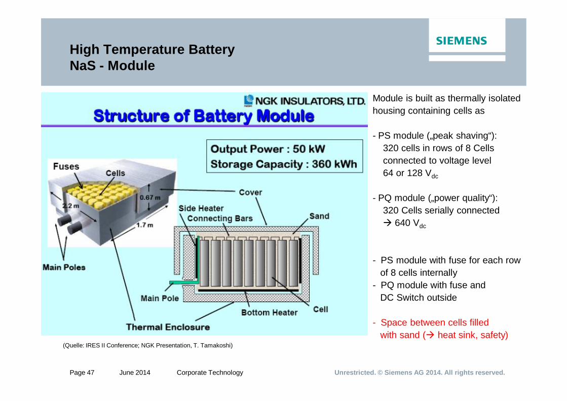
Module is built as thermally isolated housing containing cells as
- PS module („peak shaving“):320 cells in rows of 8 Cells connected to voltage level 64 or 128 Vdc
- PQ module („power quality“):320 Cells serially connected
640 Vdc
- PS module with fuse for each row of 8 cells internally
- PQ module with fuse and DC Switch outside
- Space between cells filled with sand ( heat sink, safety)
(Quelle: IRES II Conference; NGK Presentation, T. Tamakoshi)
High Temperature BatteryNaS - Module
Page 48
Unrestricted. © Siemens AG 2014. All rights reserved.Page 48 June 2014 Corporate Technology
Sodium Based Batteries – Use CasesSmoothing for wind and PV (MWh class)
Source: Japan Wind Development Co.
Aomori, Japan Futamata wind power plant
51 MW of wind turbines (1500 kW x 34 units)
34 MW NaS batteries (2000 kW x 17 units).
Battery Usage:The total power output of this facility is smoothed and peak output is controlled to be no greater than 40 MW.
Focus: Avoid Curtailment
Operation started June 2008.
Page 49
Unrestricted. © Siemens AG 2014. All rights reserved.Page 49 June 2014 Corporate Technology
High Temperature Battery NaNiCl - Basics
• Source: GE (2012)
Tubular formed cells
Pos. Electrode: NiCl2+NaAlCl4 (+FeCl3) Neg. Electrode: Na Electrolyte (solid : -Al2O3
2NaCl + Ni NiCl2 + 2Na (OCV 2,58V)
3Na + NaAlCl4 4 NaCl + Al
Usage in mobile applications and crash tests have proven safety and
robustness of NaNiCl-modules
• Temperature range: 270C - 350C• Max charge/discharge rate 1/3 .. 1/2C (Air Cooling)
• Low vapor pressure (< 1 atm up to 800C)• Less metal corrosion by halide as by S• Cell assembly in fully discharged mode (no toxic components)
• Moderate reaction Na-NaAlCl4 in case of electrolyte failure
internal shortcut leads to low resistance of failed cell; string still operable, but at lower voltagesmall fissures will be “healed” by metallic Al, reaction of failed cell will be damped
Page 50
Unrestricted. © Siemens AG 2014. All rights reserved.Page 50 June 2014 Corporate Technology
High Temperature Battery NaNiCl – ExemplaryStationary Cofigurations
Page 51
Unrestricted. © Siemens AG 2014. All rights reserved.Page 51 June 2014 Corporate Technology
NaNiCl-Battery Mobile ApplicationBredamenarinibus 240 Hybrid with a series plug in
Bredamenarinibus 240 Hybrid plug in
- Traction Motor: 2 Siemens 1PV51135 AC Induction motor 74 KW peak power with electronic differential
- Traction Inverter :2 Duo Inverter Siemens Rated Power 2X120 KVA, max current 250 A
- On board Engine:Mercedes Benz OM 904 LA E3 Diesel, max power 130 kW
- On board generator:Siemens 1FV5139 type Permanent Sincr. Motor max Power 85 kW
- Battery:3x Z5-557V-32Ah ZEBRA batteries on roof top
• Length 10.5 m (NU) or 12 m. (LU) • Weight: 19 ton full load • Passenger capacity 94 (19 seated) • Top speed 73 km/h • Pure Electric Range: 32 km• Daily operation for 16-18h with 180-220km
Battery proofed >>2000 NPC (~80%DOD per day) w/o a significant degradation of the performance. Some sets of batteries operated on downtown pure electric buses lasted for >10 years of operation.
Operation in Bologna, Italy since >10 years. The fleet is composed by 10 Iveco Down Town pure electric buses, 12 Cam Alé Hybrid buses and 11 Bredamenarinibus 240 EI Hybrid buses. Status 2010
Page 52
Unrestricted. © Siemens AG 2014. All rights reserved.Page 52 June 2014 Corporate Technology
Li-Air Battery – RnD LevelPromise of very high power and energy densities
Page 53
Unrestricted. © Siemens AG 2014. All rights reserved.Page 53 June 2014 Corporate Technology
Some Exemplary Battery Storage Solutions
Page 54
Unrestricted. © Siemens AG 2014. All rights reserved.Page 54 June 2014 Corporate Technology
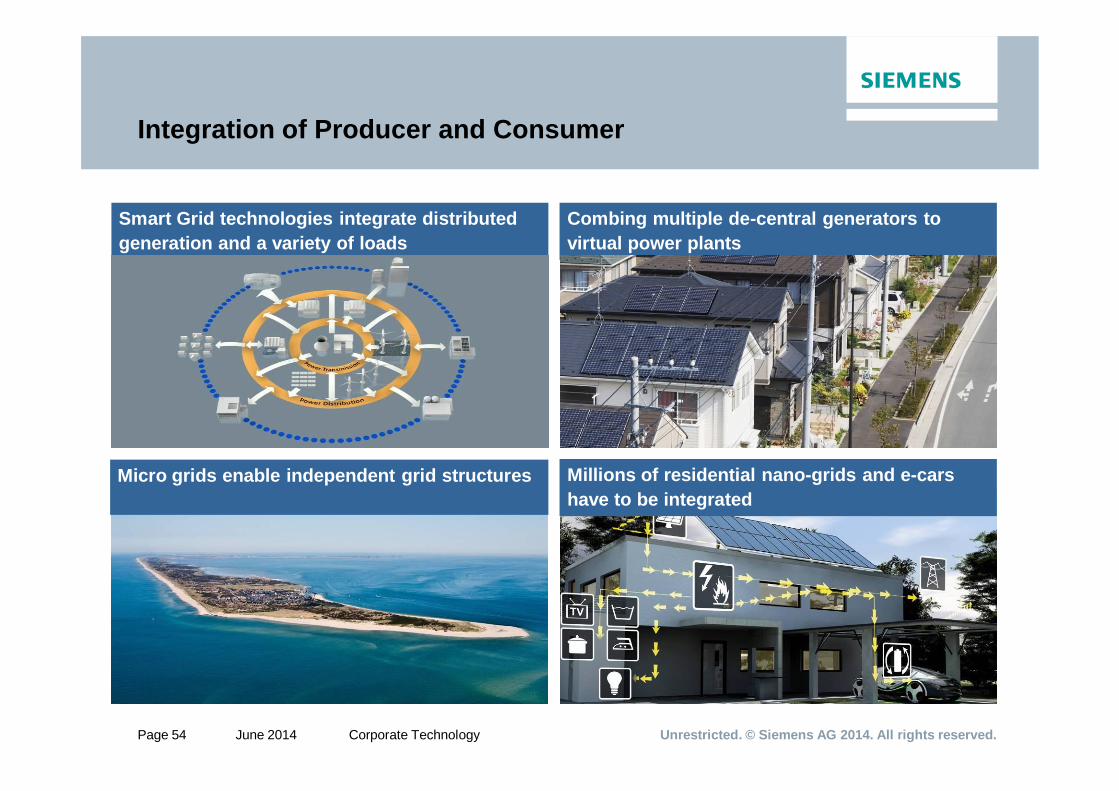
Integration of Producer and Consumer
Combing multiple de-central generators to virtual power plants
Smart Grid technologies integrate distributed generation and a variety of loads
Micro grids enable independent grid structures Millions of residential nano-grids and e-cars have to be integrated
Page 55
Unrestricted. © Siemens AG 2014. All rights reserved.Page 55 June 2014 Corporate Technology
Dual Use of Residential PV+StorageBatteries in a SWARM
Power grid
Decentralized battery storage
Appliances
PV
Power plant
Factory
Battery
Appliances
Battery
Appliances
Battery
Appliances
SWARMControlCenterBattery
Appliances
…
PV
PV
PV
Internetconnectionto batteries
PV
Water storagepower plant
Appliances
Renewablepower plant
Decentralized battery storagepower plant
The expected numerous home storage systems to be installed in a future grid interact on the grid - not only by supporting it in case of congestion relief by simply storing surplus energy and shifting energy from PV (time shift) from day to night times
- but can be used in joint swarm approach to provide (primary) grid services, too.
Page 56
Unrestricted. © Siemens AG 2014. All rights reserved.Page 56 June 2014 Corporate Technology
Frequency containment reserve handles short-term grid imbalances as a solidary Europe-wide action
Source: SNB, Regelleistung.net
Grid balancing - Examples for principle mechanisms
Longer term grid balancing needs to be handled by Bilanzkreis2)
1) TSO = Transmission Service Provider2) Europe divided in control areas for TSOs. Every TSO control area contains many accounting groups (Bilanzkreise) of meters.3) After power demand became less than contracted supply
GW
tHours
Scheduled power demand= scheduled power supply
Frequency restoration and tertiary reservereplace frequency containment within minutes
30 sec 15 min 60 min
30 sec3)15 min3) 60 min3)
Power demand equals
contrac-ted
supply
Demand for additional powerDemand for additional
consumption
Actual powerdemand
Primary control energy provided by all TSOs1) in Europe
Secondary and tertiary control energy provided by TSO in whose area deviation occurred
Control energy provided by Bilanzkreis2) where deviation
occurred
Frequency containment reserve reacts within seconds
Seconds
Additional consumption delivered by primary control
Additional power deliveredby primary control
Page 57
Unrestricted. © Siemens AG 2014. All rights reserved.Page 57 June 2014 Corporate Technology
Field Test: Impact of Virtual Storage Plant based on Home Storage + PV on the DSO / TSO Grid
N-ergie 1) Germany
Grid size 26703 km
Energy consumed p.a. 13.6 TWh ~ 670 TWh
Power 2% of GER 40..77 GW
PV units <10kw >40000 >700000
• 1) Source map: www.N-ergie.com
10% PV w/ ESS + Grid N-ergie Germany
Units ~ 4000 ~70000
Power avail. (66%) 2) 47.5 MW 0.83 GW
Capacity inst. 88 MWh 1.54 GWh
Throughput p.a. 3) 5.04 GWh 88.2 GWh
Fieldtest SWARM N-ergie Germany
Units ~ 80 -
Power avail. (66%) 2) 1.10 MW -
Capacity inst. 1.76 MWh -
Throughput p.a. 3) 100.8 MWh -
Ausstattung von 10 % der PV Anlagen (heute) mit regelbaren Speichern ermöglicht 1% Regelleistung
(Schätzung ~3% benötigt)
2) Usually only 66% of the batteries usable for Grid Service (maintenace, full empty)3) Increase of self consumption by ~30% and avg. Consumption of 4200kWh p.a.
Electrical network of N-ergie
Page 58
Unrestricted. © Siemens AG 2014. All rights reserved.Page 58 June 2014 Corporate Technology
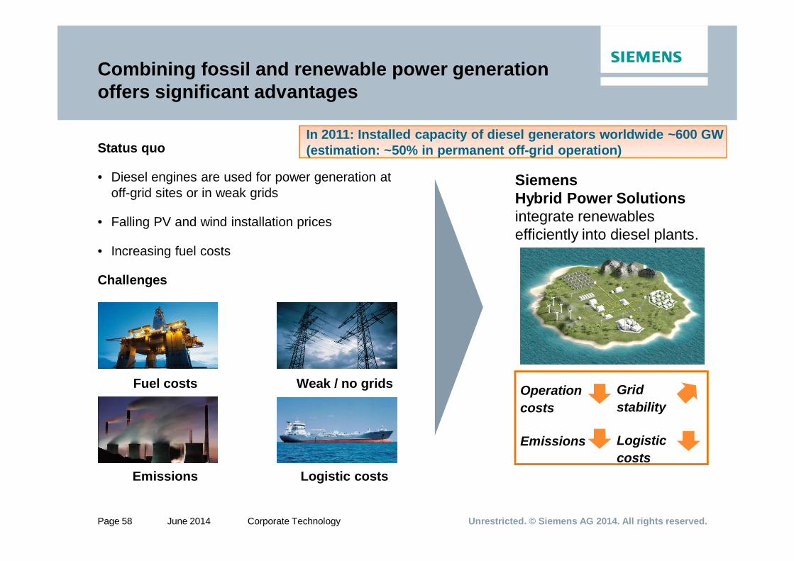
Combining fossil and renewable power generation offers significant advantages
Status quo
• Diesel engines are used for power generation at off-grid sites or in weak grids
• Falling PV and wind installation prices
• Increasing fuel costs
Challenges
SiemensHybrid Power Solutionsintegrate renewablesefficiently into diesel plants.
Logistic costsEmissions
Fuel costs Weak / no grids Grid stability
Logistic costs
Operation costs
Emissions
In 2011: Installed capacity of diesel generators worldwide ~600 GW(estimation: ~50% in permanent off-grid operation)
Page 59
Unrestricted. © Siemens AG 2014. All rights reserved.Page 59 June 2014 Corporate Technology
Complete, optimized solutions that minimize your risk
Customer benefits:
• Reduced fuel costs by up to 60 %
• Reduced CO2 emissions by up to 60 %
• Reduced logistic/transportation costs
• High grid stability
One-stop solution by Siemens
• Intelligent combination of renewable energy sources with diesel engines and storage
• Optimized operation based on cost functions, forecasts and real-time data
• Realization of minimal operation costs
Siemens Hybrid Power Solutions
• Manage the complexity of diesel power installations with volatile renewable energy sources
• Are customized for different local conditions (wind or solar intensity and specific loads)
• Ensure high grid stability of renewable integration thanks to integrated energy storage
Page 60
Unrestricted. © Siemens AG 2014. All rights reserved.Page 60 June 2014 Corporate Technology
SIESTORAGEStable and reliable power supply
Use Case Example: Diesel Offset Application
Page 61
Unrestricted. © Siemens AG 2014. All rights reserved.Page 61 June 2014 Corporate Technology
BMBF Funded Project IRENE BatteryLocal Storage for DSO Grids w/ high share of RE
• Maße (L*B*H): 7,3m * 2,4m * 3,1m• Gewicht: 16t
DimensionDimension
Installed 2012 September
Page 62
Unrestricted. © Siemens AG 2014. All rights reserved.Page 62 June 2014 Corporate Technology
Energy Storage - Industrial SolutionsExample: Mass Transport
DLC-energy storage unit Sitras MES
Traction battery for Sitras HES
Parameter DLC-energy storage unit
NiMH-Traction battery
Voltage 190 V - 480 V 528 V
Maximum current 2 x 300 A 220 A
Maximum power 2 x 144 kW 85 kW
Usable energy content 2 x 0.425 kWh 18 kWh
contact: Michael Meinert, Siemens Sector Industry, Mobility Divisioncontact: Michael Meinert, Siemens Sector Industry, Mobility Division, mailto:[email protected]
Objectiverecovery of brake energy
Maximale Leistung 0,7 MW
Nutzbarer Energieinhalt 1 ... 3,1 kWh
Stationary
mobiley
Page 63
Unrestricted. © Siemens AG 2014. All rights reserved.Page 63 June 2014 Corporate Technology
Sto
p A
Sto
p B
Sto
p C
Sto
p D
Sto
p E
Sto
p F
Sto
p G
Sto
p H
Sto
p I
Sto
p J
Sto
p K
Sto
p L
Stop
M
Sto
p N
30
40
50
60
70
80
90
100
1100 60 120 180 240 300 360 420 480 540 600 660 720 780 840 900 960 1020
Zeit / s
Lade
zust
and
/ %
0
20
40
60
80
100
120
140
160
Ges
chw
indi
gkei
t / k
m/h
DSK (energieeffizienter & oberleitungsloser Betrieb)Traktionbatterie (oberleitungsloser Betrieb)Geschwindigkeit
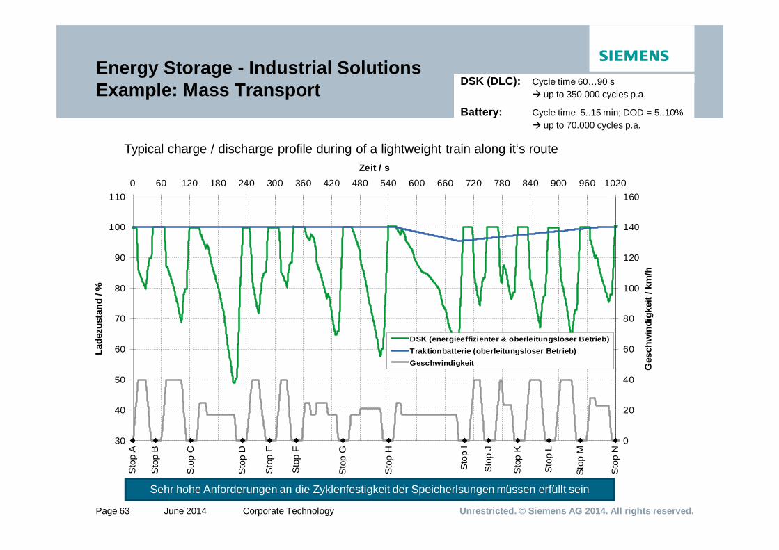
Energy Storage - Industrial SolutionsExample: Mass Transport
Sehr hohe Anforderungen an die Zyklenfestigkeit der Speicherlsungen müssen erfüllt sein
Typical charge / discharge profile during of a lightweight train along it‘s route
DSK (DLC): Cycle time 60…90 sup to 350.000 cycles p.a.
Battery: Cycle time 5..15 min; DOD = 5..10%up to 70.000 cycles p.a.
DSK (DLC): Cycle time 60…90 sup to 350.000 cycles p.a.
Battery: Cycle time 5..15 min; DOD = 5..10%up to 70.000 cycles p.a.
Page 64
Unrestricted. © Siemens AG 2014. All rights reserved.Page 64 June 2014 Corporate Technology
Long term Storage - Large Scale Storage
Pumped Hydro and Power to Gas
Page 65
Unrestricted. © Siemens AG 2014. All rights reserved.Page 65 June 2014 Corporate Technology
potential energy German electricity grid; selected situation in 2007
mitigation errors are in the GWh-range !
energy densities of large-scale options:
0,5 5
140
0
50
100
150
200
[ kW
h/m
³ ]
pumpedhydro [1]
CAES [3] H2 compr.[2]
[1]: for h = 200 m [2]: compressed to 50 bar[3]: typical compression 70 bar
pressurized air
compressionenergy
H2
chemical energy
Pumped Hydro
CAES
Hydrogen
Energy StorageLarge Scale Energy Storage – Classic Approach
Page 66
Unrestricted. © Siemens AG 2014. All rights reserved.Page 66 June 2014 Corporate Technology
Innovative Approach: Pump hydro using Subsea Vacuum Spheres
5) flow funnel
3) subseapower cable
700 m
30 m
vapor(20 mbar)
fillinglevel
sea level
wind turbine
6) pump-turbine + gen-set(inside :0.3….3 bar / outside: 80 bar)
sea bottom
steepcoast
water
4) concrete sphere
„Subsea Pumped Hydro Storage“
Concrete sphere 30m Ø - 700 m below sea levelCapacity: up to 20 MWhPower : up to 6 MWCharge Time ~3.5hDischarge time ~3.5hEfficiency up to 80 .. 85%
1) Control(monitor pump-turbine operation,e.g. blocking, hydraulic shock …)
2) Substation / Power Electronics
3) Subsea power cable + distribution(e.g. for a farm of vacuum spheres)
4) Concrete sphere(typicall y 30m Ø w/ 3m walls)
5) In/out flow funnel w/ protection(mesh ort similar)
6) Pumpturbine (Kaplan) + gen-set
Components: „Under Water - Pumped Hydro Storage Plant“ (UW – PHES)
grid
1) control2) substation
RnD Targets: Typical System Cost ~1600 €/kW 475 €/kWhLifetime 10 to 15 yrs
Page 67
Unrestricted. © Siemens AG 2014. All rights reserved.Page 67 June 2014 Corporate Technology
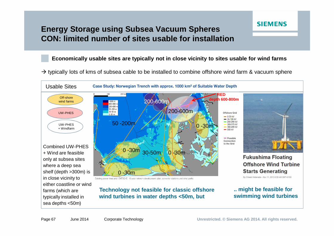
Energy Storage using Subsea Vacuum Spheres CON: limited number of sites usable for installation
Economically usable sites are typically not in close vicinity to sites usable for wind farms
typically lots of kms of subsea cable to be installed to combine offshore wind farm & vacuum sphere
UW-PHES
Off-shorewind farms
Combined UW-PHES + Wind are feasible only at subsea sites where a deep sea shelf (depth >300m) is in close vicinity to either coastline or wind farms (which are typically installed in sea depths <50m)
UW-PHES + Windfarm
REDdepth 600-800m
50 -200m
30-50m
200-600m
0 -30m
0 -30m 0 -30m
0 -30m
200-600m
Usable Sites
Technology not feasible for classic offshore wind turbines in water depths <50m, but
.. might be feasible for swimming wind turbines
Page 68
Unrestricted. © Siemens AG 2014. All rights reserved.Page 68 June 2014 Corporate Technology
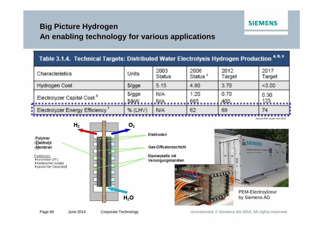
PEM-Electroylzeurby Siemens AG
Big Picture HydrogenAn enabling technology for various applications
• Source RnD Goals: IHS 2013
Page 69
Unrestricted. © Siemens AG 2014. All rights reserved.Page 69 June 2014 Corporate Technology
Grid
Electrolysis
Power Generation Conversion & Storage Utilization
Photovoltaic
Wind Power Inter-mittent
+ -
O2 H2
H2O
Biogas Plant
“Steady”
CO2
H2
H2
Direct utilization
Industry
IndustryUsage of H2NH3
CC-Turbine
Energy Re-ElectrificationSNG
MobilityH2 FuelSNG FuelM3 Gasoline
H2
CH4
H2 storage
CO2 utilization
H2
Injection to NG Grid
Fuel Substitute
CH4
CH3OH
Fossil Power
CO2
Steady
Big Picture HydrogenAn enabling technology for various applications
SNG M3
Page 70
Unrestricted. © Siemens AG 2014. All rights reserved.Page 70 June 2014 Corporate Technology
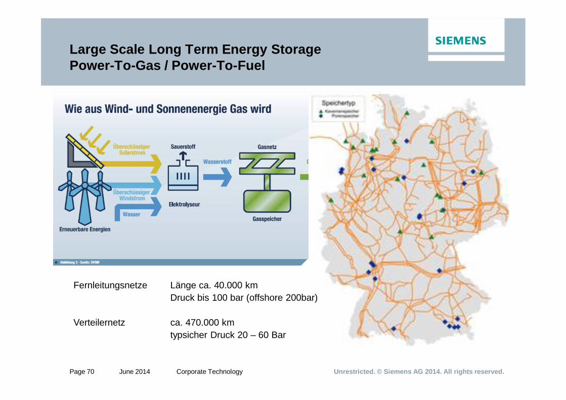
Large Scale Long Term Energy StoragePower-To-Gas / Power-To-Fuel
Fernleitungsnetze Länge ca. 40.000 kmDruck bis 100 bar (offshore 200bar)
Verteilernetz ca. 470.000 kmtypsicher Druck 20 – 60 Bar
Page 71
Unrestricted. © Siemens AG 2014. All rights reserved.Page 71 June 2014 Corporate Technology
M1-Gasoline1)
1) Up to 3% already allowed (M3)
Fuel Mix
Methanol Fuel SubstituteThe Impact of Fuel Substitution on CO2 Emissions
Page 72
Unrestricted. © Siemens AG 2014. All rights reserved.Page 72 June 2014 Corporate Technology
Thermal Storage as competitor to Power-to-Gas
Page 73
Unrestricted. © Siemens AG 2014. All rights reserved.Page 73 June 2014 Corporate Technology
Thermal Heat Storage as Eco-Power-BufferDemo Project N-ergie
Demo Project Power to Heat - Thermal Energy Storage
Owner N-Ergie
Invest 17 Mio € (11,3 €/kWhthermal)
Type: Two-Zone-Liquid-Water Thermal Energy Storage
Tower shaped tank with 2 electrical heaters
El. Power 2x 25MW
Thermal Capacity 1,5 GWh
Height 70m
Radius 23m
Volume 33 Mio liter of water
Temperature level slightly above 100 Celsius
Objective: Decoupling of heat & power consumption of existing CHP-Plants (Flexibility)
Page 74
Unrestricted. © Siemens AG 2014. All rights reserved.Page 74 June 2014 Corporate Technology
The role of long term heat storages in the Danish energy system – solar district heating
Lots of local district heating systems + small CHP installed between 1980 and now
Page 75
Unrestricted. © Siemens AG 2014. All rights reserved.Page 75 June 2014 Corporate Technology
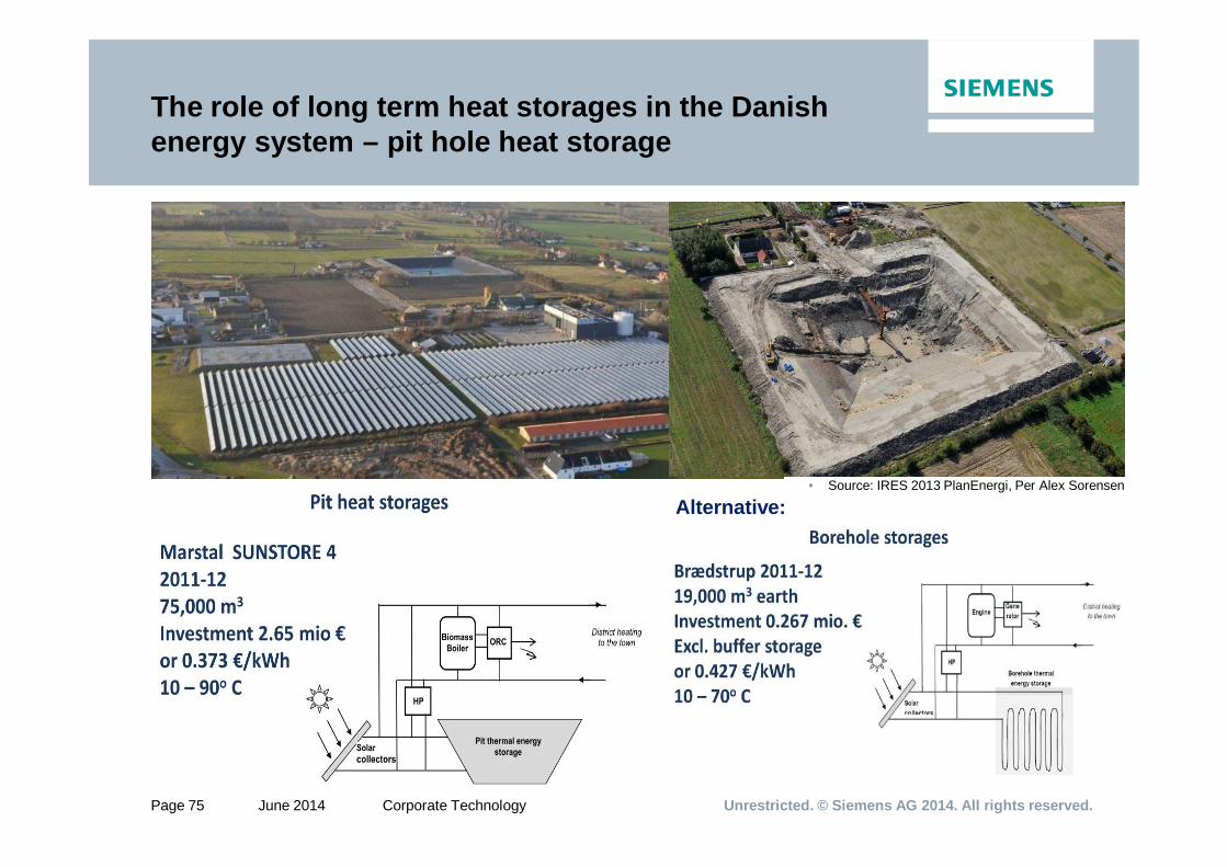
The role of long term heat storages in the Danish energy system – pit hole heat storage
Alternative:• Source: IRES 2013 PlanEnergi, Per Alex Sorensen
Page 76
Unrestricted. © Siemens AG 2014. All rights reserved.Page 76 June 2014 Corporate Technology
FinallyFamous eCars
Apollo 17 Lunar Rover
• Siemens Viktoria 1905
Paketzustellwagen 1922
Tesla S
BMW I8
around 1890
Page 77
Unrestricted. © Siemens AG 2014. All rights reserved.Page 77 June 2014 Corporate Technology
Thanks for your Thanks for your attentionattention!!