24
Schutzvermerk / Copyright-Vermerk Copyright © Siemens AG 2011. All rights reserved Siemens Mechatronic Systems Certification Program Displacement Displacement - - Step Diagram Step Diagram

Schutzvermerk / Copyright-VermerkCopyright © Siemens AG 2011. All rights reserved
Siemens Mechatronic Systems Certification
Program
DisplacementDisplacement--Step DiagramStep Diagram

Siemens Professional EducationOCT-2011Slide 2Copyright © Siemens AG 2011. All rights reserved
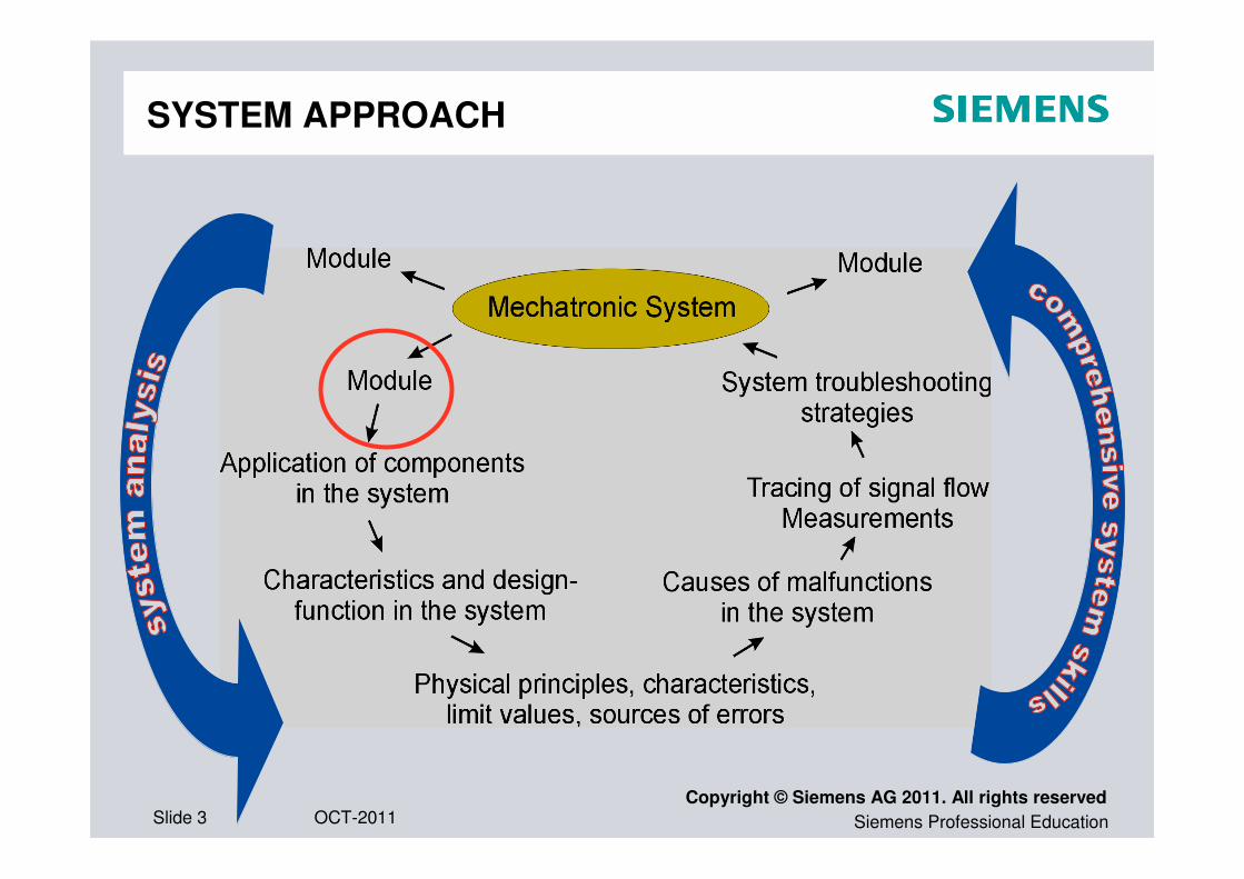
A Siemens Certified Mechatronic Systems Assistant will functionA Siemens Certified Mechatronic Systems Assistant will function
as a wellas a well--grounded machine operator in a complex system, grounded machine operator in a complex system,
with responsibility for efficient operation of the equipment with responsibility for efficient operation of the equipment
with minimal downwith minimal down--times. times.
He or she will be able to:He or she will be able to:
•• Localize malfunctions, identify causes and sources of Localize malfunctions, identify causes and sources of
malfunctions, correct malfunctions where possible malfunctions, correct malfunctions where possible ……
• Read and understand the technical documents, reports Read and understand the technical documents, reports
and outlines specific to the system and subsystems and outlines specific to the system and subsystems ……
JOB PROFILE
Siemens Professional EducationOCT-2011Slide 3Copyright © Siemens AG 2011. All rights reserved
SYSTEM APPROACH
Siemens Professional EducationOCT-2011Slide 4Copyright © Siemens AG 2011. All rights reserved
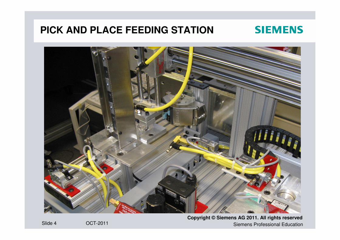
PICK AND PLACE FEEDING STATION
Siemens Professional EducationOCT-2011Slide 5Copyright © Siemens AG 2011. All rights reserved
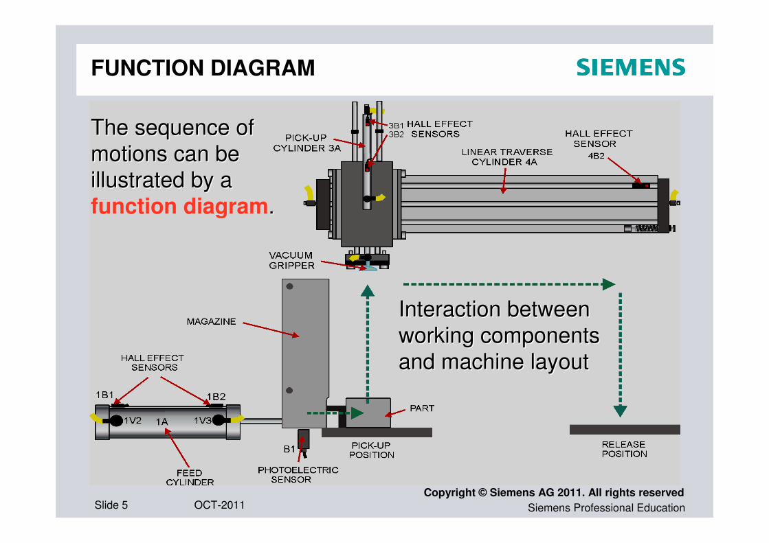
The sequence of The sequence of
motions can be motions can be
illustrated by a illustrated by a
function diagram..
Interaction between Interaction between
working componentsworking components
and machine layoutand machine layout
FUNCTION DIAGRAM

Siemens Professional EducationOCT-2011Slide 6Copyright © Siemens AG 2011. All rights reserved
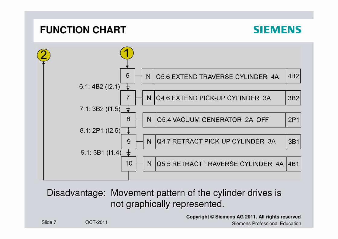
FUNCTION CHART
Siemens Professional EducationOCT-2011Slide 7Copyright © Siemens AG 2011. All rights reserved
FUNCTION CHART
Disadvantage: Movement pattern of the cylinder drives is Disadvantage: Movement pattern of the cylinder drives is
not graphically represented. not graphically represented.

Siemens Professional EducationOCT-2011Slide 8Copyright © Siemens AG 2011. All rights reserved
DISPLACEMENT-STEP DIAGRAM

Siemens Professional EducationOCT-2011Slide 9Copyright © Siemens AG 2011. All rights reserved
STEPS
DISPLACEMENTS
DISPLACEMENT-STEP DIAGRAM
Siemens Professional EducationOCT-2011Slide 10Copyright © Siemens AG 2011. All rights reserved
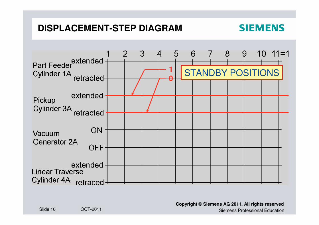
DISPLACEMENT-STEP DIAGRAM
STANDBY POSITIONS10

Siemens Professional EducationOCT-2011Slide 11Copyright © Siemens AG 2011. All rights reserved
DISPLACEMENT-STEP DIAGRAM
MOVEMENTS (diagonal lines)
STANDBY POSITIONS
(horizontal lines)

Siemens Professional EducationOCT-2011Slide 12Copyright © Siemens AG 2011. All rights reserved
DISPLACEMENT-STEP DIAGRAM

Siemens Professional EducationOCT-2011Slide 13Copyright © Siemens AG 2011. All rights reserved
ERROR SITUATION
Pickup cylinder moves downward to the pickPickup cylinder moves downward to the pick--up position, the system stopsup position, the system stops..
executed not executed
Siemens Professional EducationOCT-2011Slide 14Copyright © Siemens AG 2011. All rights reserved
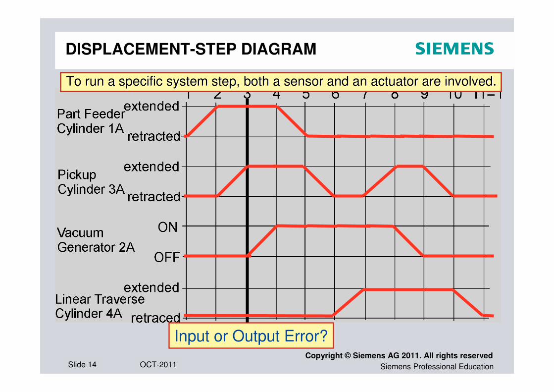
DISPLACEMENT-STEP DIAGRAM
To run a specific system step, both a sensor and an actuator areTo run a specific system step, both a sensor and an actuator are involved.involved.
Input or Output Error?
Siemens Professional EducationOCT-2011Slide 15Copyright © Siemens AG 2011. All rights reserved
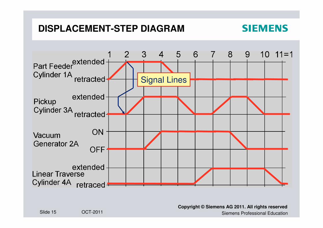
DISPLACEMENT-STEP DIAGRAM
Signal Lines
Siemens Professional EducationOCT-2011Slide 16Copyright © Siemens AG 2011. All rights reserved
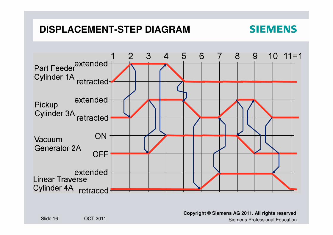
DISPLACEMENT-STEP DIAGRAM
Siemens Professional EducationOCT-2011Slide 17Copyright © Siemens AG 2011. All rights reserved
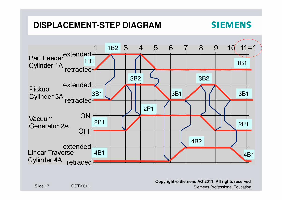
DISPLACEMENT-STEP DIAGRAM
1B2
1B1
3B2
2P1
3B1
4B2
3B2
2P1
3B1
4B1
1B1
2P1
3B1
4B1

Siemens Professional EducationOCT-2011Slide 18Copyright © Siemens AG 2011. All rights reserved
DISPLACEMENT-STEP DIAGRAM
1B2
1B1
3B2
2P1
3B1
4B2
3B2
2P1
3B1
4B1
1B1
2P1
3B1
4B1
1M1 3M1 2M1 1M1 3M2 4M1 3M1 2M2 3M2 4M2
Siemens Professional EducationOCT-2011Slide 19Copyright © Siemens AG 2011. All rights reserved
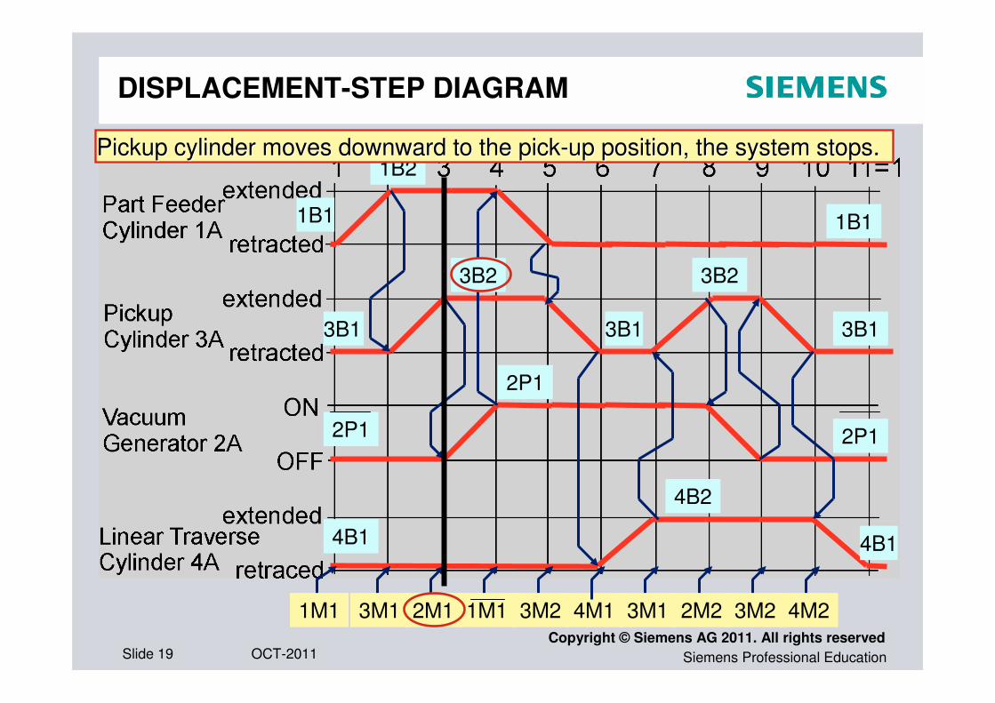
DISPLACEMENT-STEP DIAGRAM
1B2
1B1
3B2
2P1
3B1
4B2
3B2
2P1
3B1
4B1
1B1
2P1
3B1
4B1
1M1 3M1 2M1 1M1 3M2 4M1 3M1 2M2 3M2 4M2
Pickup cylinder moves downward to the pickPickup cylinder moves downward to the pick--up position, the system stopsup position, the system stops..
Siemens Professional EducationOCT-2011Slide 20Copyright © Siemens AG 2011. All rights reserved
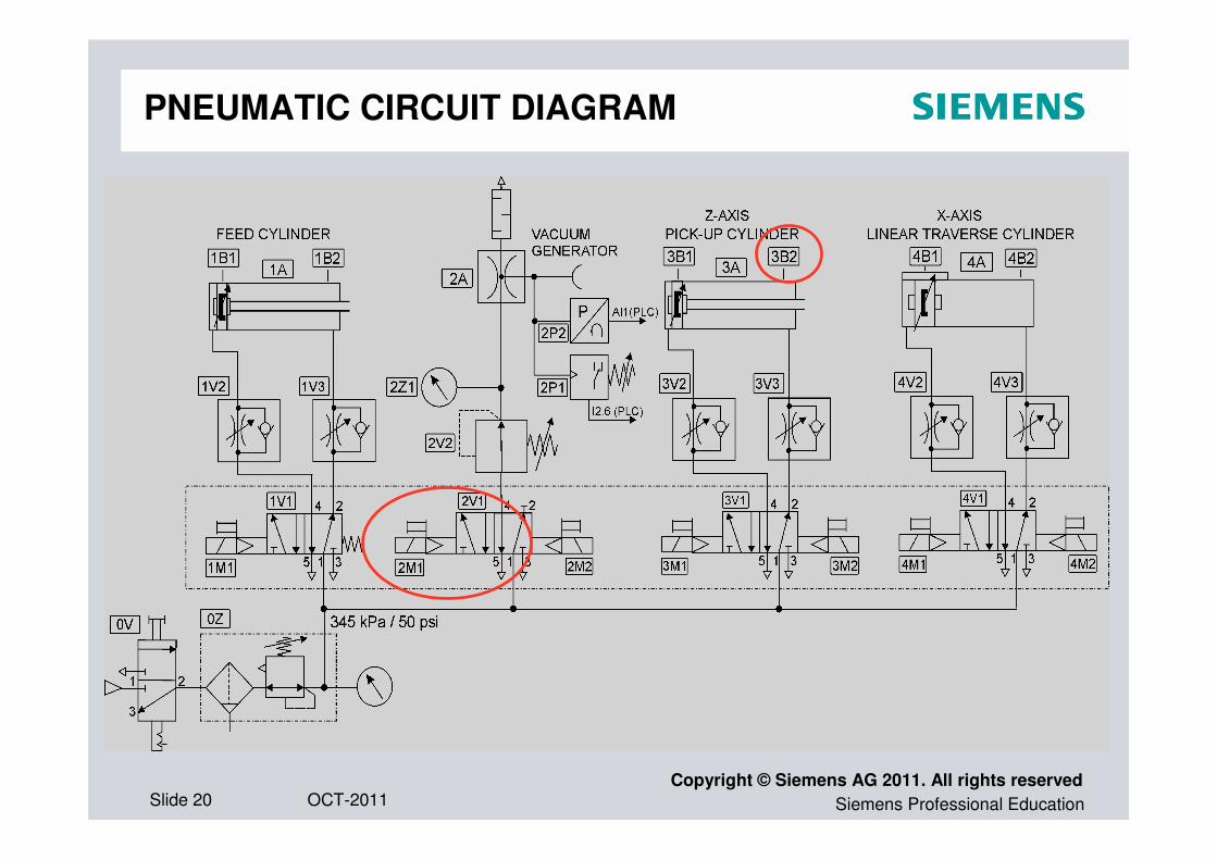
PNEUMATIC CIRCUIT DIAGRAM
Siemens Professional EducationOCT-2011Slide 21Copyright © Siemens AG 2011. All rights reserved
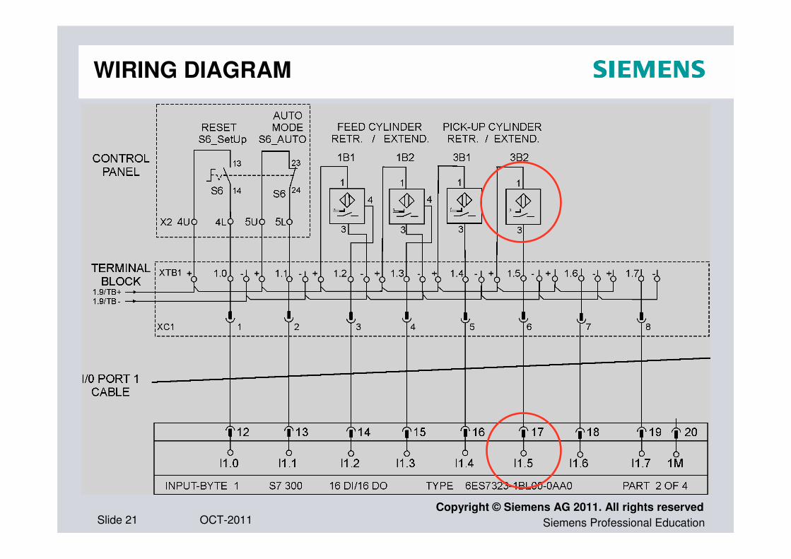
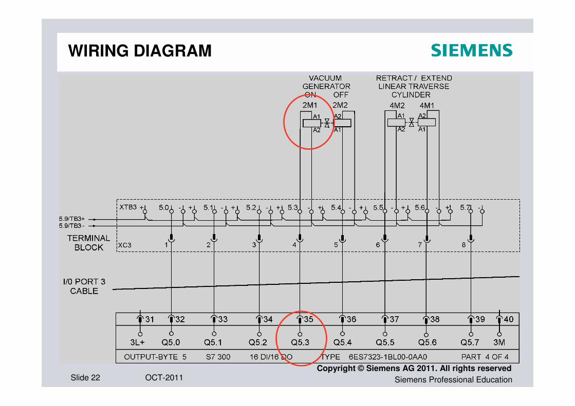
WIRING DIAGRAM
Siemens Professional EducationOCT-2011Slide 22Copyright © Siemens AG 2011. All rights reserved
WIRING DIAGRAM
Siemens Professional EducationOCT-2011Slide 23Copyright © Siemens AG 2011. All rights reserved
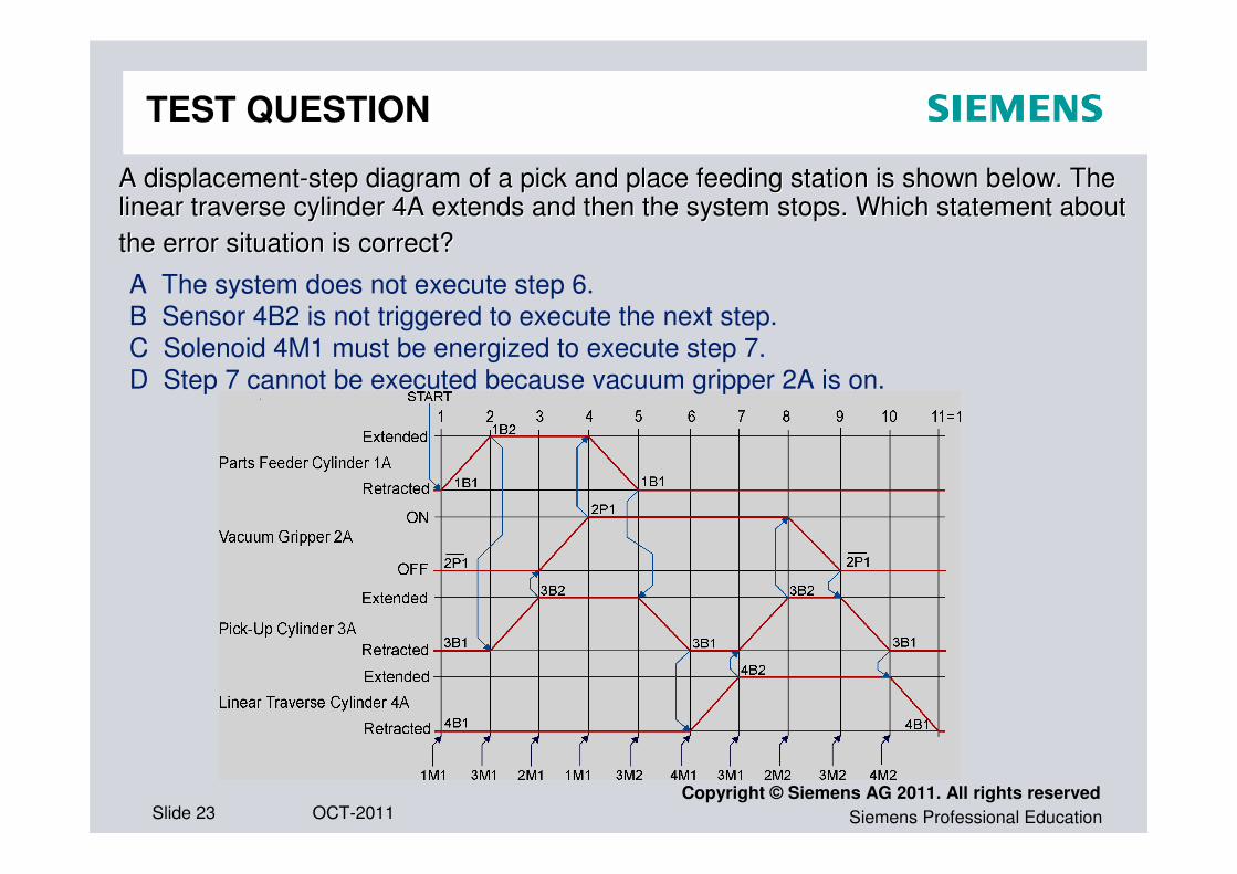
TEST QUESTION
A displacementA displacement--step diagram of a pick and place feeding station is shown below.step diagram of a pick and place feeding station is shown below. The The linear traverse cylinder 4A extends and then the system stops. Wlinear traverse cylinder 4A extends and then the system stops. Which statement about hich statement about
the error situation is correct?the error situation is correct?
A The system does not execute step 6.
B Sensor 4B2 is not triggered to execute the next step.
C Solenoid 4M1 must be energized to execute step 7.
D Step 7 cannot be executed because vacuum gripper 2A is on.
Siemens Professional EducationOCT-2011Slide 24Copyright © Siemens AG 2011. All rights reserved
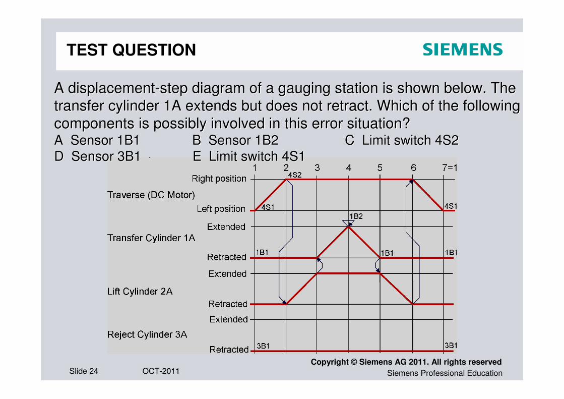
A displacementA displacement--step diagram of a gauging station is shown below. The step diagram of a gauging station is shown below. The
transfer cylinder 1A extends but does not retract. Which of the transfer cylinder 1A extends but does not retract. Which of the following following
components is possibly involved in this error situation? components is possibly involved in this error situation? A Sensor 1B1 B Sensor 1B2 C LimA Sensor 1B1 B Sensor 1B2 C Limit switch 4S2it switch 4S2
D Sensor 3B1 D Sensor 3B1 E Limit switch 4S1E Limit switch 4S1
TEST QUESTION


