20
Sierra Technical ManualPage 1

Sierra Technical ManualPage 1
Page 2Sierra Technical Manual Sierra Technical ManualPage 3
Table of ContentsSet up for Session Series 1Set up for Royalty and Crown Series 1Breakdown: 1Electric circuit & pickup - removal and replacement: 1Pickups 2Pickup removal & replacement 2Tuning 2Tuning pedals & knee levers 2Half stops 2Changer 3To tune 3Change-lok 3Leverage Selection 4Theory 4Procedure for selection 4Making Changes 5Bell crank relocation: 5Bell crank addition and re-assembly: 5Tuning new changes: 5Knee levers 6Trouble shooting 6Pedal travel (Figure 15) 6Tension springs 6Untrue return 6Insufficient travel 6Excessive travel 7Slippage 7Lubrication 7Strings 7Adjustments 7Pedal rods 7Mobile knee levers (Figure 8 & 9) 7
Page 2Sierra Technical Manual Sierra Technical ManualPage 3
Set up for Session Series
From the in-case position, Figure 20 & Figure 22, insert the legs into the leg sockets and tighten the leg lock handle. The small pin on the leg stub must be in line with the slot of the leg socket. Insert the stub until the leg is even with the guitar body, then rotate the leg 90 degrees 10 be square with the body and the front legs pedal rack mounting pins facing the from, and the back legs height adjustment facing the back.
Install the pedal rack by sliding the lock plates to the outside of the leg slots and position the rack on the legs so that the pins on the legs are inserted into the pedal rack. Then slide the locks in place and tighten the knobs. The pedal rods are numbered with number 1 at the string tuning end of the guitar. Install the hook end of the rod on the cross shaft arm in either hole (The hole closest to the shaft will provide the shortest pedal action and the hole farthest from the cross shaft will provide the easiest pedal action.) Then attach the slide ball end on the ball at the pedal. Again, there are three positions to adjust pedal action to your preference.
Set up for Royalty and Crown Series
Loosen leg knobs and turn leg into up position; the snap lock will automatically align the leg. On the front leg there are two pins which match up with holes in the pedal rack. Slide pedal rack lock plates away from the end of the pedal rack and align the pins to the holes. Now, slide the plates toward the ends of the pedal rack and tighten the knobs. Pedal rods are numbered; #1 is closest to the tuning keys. Install the pedal rod slip ball joint on the ball of the pedal, put the other end into the cross shaft ball with slip ball joint. Centering leg lock knobs for aesthetic reasons may be done with shims available from the factory.
Breakdown:
Reverse above procedure but slightly loosen legs before placing the guitar in its case. After folding the legs in the case, re-tighten each leg to keep it from moving while in the case.
Electric circuit & pickup - removal and replacement:
Doubles: on back side of guitar (closest to player) with guitar in playing position and player seated behind.
1. Three-way rocker switch closest to changer is the neck selector switch; moving the switch to right activates the C6 (back neck); moving the switch to center activates both necks; moving the switch to left activates E9 (front neck).
2. Three-way rocker switch in center controls the three pickup tones for the front neck (E9).
3. Three-way rocker switch furthest to left controls the three pickup tones for the back neck (C6).
Singles: one three-way rocker switch on backside of guitar (changer end) controls the three pickup tones.
Page 4Sierra Technical Manual Sierra Technical ManualPage 5
Pickups
To please the varying tastes of our customers, we developed and pioneered modular pickups. Custom pickups are wound with different tonal qualities in mind. The opportunity for the player to select from our many different pickups allows him to custom-tailor his guitar to his own tonal desires.
Pickup removal & replacement
Slide out present pickup. Notice there is a dovetail track with three or four brass spring-loaded pins depending on your model. Using the un-lipped end of the pickup, gently depress the three pins and mate the dovetail on pickup with the track, and slide the pickup into place. Alignment and pin depression is essential!
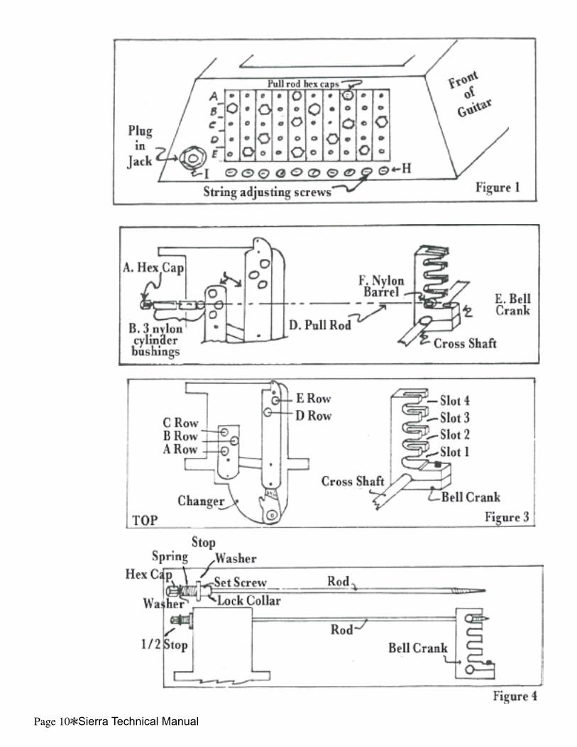
Tuning
To better understand tuning procedures of your Sierra, study Figure 2, and compare to your guitar. Figure 2 shows the relationship from pedal to changer. A hex capped pull rod is installed with 2 or 3 nylon cylindrical bushings (1 or 2 lengthwise, 1 crosswise). These bushings are what contact the changer when a pedal is used. One short bushing accommodates the raise holes, (Figure 1, rows A., B, C); one long and one short accommodated lowers, (Figure 1, rows D & E) The properly used rod is then guided through the proper changer hole for raises or lowers. A bell crank with a threaded barrel shape nut is then aligned and tightened on the cross shaft. The rod is then threaded through the nylon nut. When the cross shaft is rotated by a pedal or lever, the bell crank on it moves the pull rod. The cylindrical bushings thereby come into contact with the changer finger, moving it to make a change.
Tuning pedals & knee levers
Tuning a Sierra is not complex. The guitar is tuned open to an electronic tuner, fork, or whatever, and then tempered to sound pleasing to your ear. Pedals and knee levers are tuned at the right end plate. With guitar in playing position, the 3 top most rows in the changer are raises, Figure 1, the bottom 2 rows are lowers. To adjust, turn brass pull rod hex cap clockwise to increase your change or counter-clockwise to decrease it. This is the same for raises or lowers. Caution: do not over-tighten these rods. A good rule is to leave 1/32” to 1/16” of free-play in each rod. (This is explained in the “trouble shooting” section.)
Half stops
The Sierra half stop consists of an extra bell crank on the lever shaft and a special half stop rod. This rod, Figure 4, visible at the endplate, is easily recognized from the others by a spring mounted on it. The normal pull rod operates the changer, e.g. 2nd string E9th D# to C#. The spring loaded half slop rod has no nylon bushings and will not affect the changer. It travels freely until the spring begins to compress. This point of pressure gives the knee lever a defined stop-feel and is adjusted at the endplate to the half tone between a whole step, as D between the D# and C#. The amount of “feel” is also adjustable by lengthening or shortening the preset compression of the spring by resetting of the lock nuts or lock collars holding the spring. When resetting for “harder feel,” make sure spring does not fully compress before full tone note can be made.
Page 4Sierra Technical Manual Sierra Technical ManualPage 5
Changer
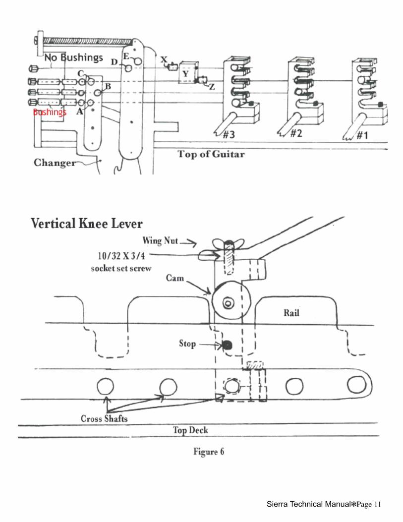
The Sierra changer is an all-pull triple raise/double lower system. This means that any string can be raised 3 separate times and lowered 2 times. To accommodate the players with more complex tuning specs, we offer additional raise-and-lower capabilities. By means of a “tandem” system the Sierra can easily achieve these multi-change situations and still be tunable at the endplate. In Figure 5, you can see that the two raises are utilizing shafts #1 and #2, E to F and E to F#. To get another raise, E to F# again, a rod with no bushings is threaded through a bell crank in position D. On it is a collar with set screws (X) and a two holed slide block (Y). The rod on #1 passes through (Y) with a collar (Z) which is tightened on the pull rod ahead of the slide block (Y). As #3 is moved, its collar moves the slide block which contacts the collar on #1. Since #3 has no bushings, it will not affect the changer; #3 works directly on rod #1, which in turn will affect the changer.
To tune
Turn pull rod either clockwise or counterclockwise, turning #3. Clockwise will decrease the distance between X&Y, thus raising a greater distance; counter-clockwise will do just the opposite.
Change-lok
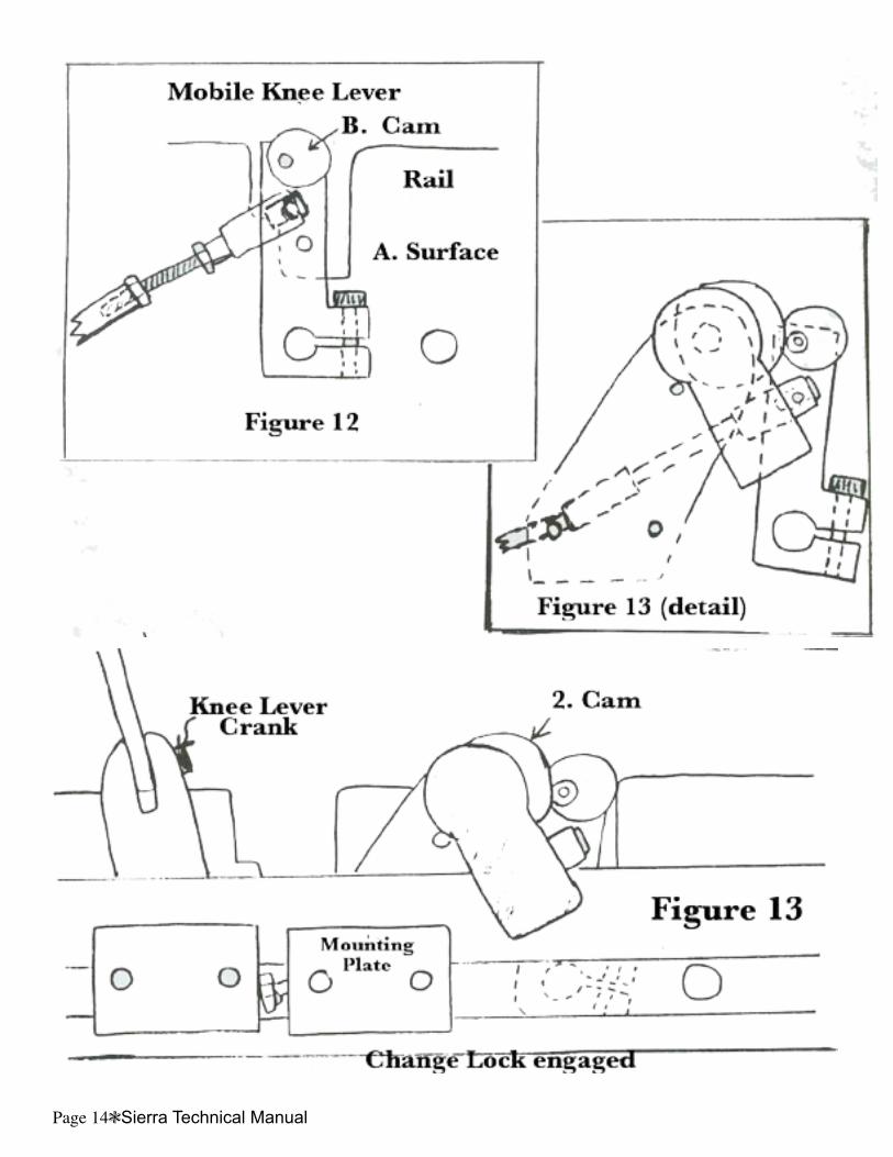
The “change-lok” is used for locking a change or changes into place: it maintains the change until released- Change-loks are hand-operated, and usually used with the universal tunings. The E9th with change-lok on E’s to E-flat gives a B6th. The player can then use all his jazz pedals without being hampered by holding a knee lever in for an extended time. When he releases it, he is back to Nashville E9lh. Fig. 13 depicts this mechanism. The change-lok is tuned as follows:
1. Adjust change-lok cam so that maximum travel is opposite knob direction.2. Adjust change-lok and mount plate so that with the cam engaged the knee lever is pressed hard against stop.
The change-lok, when engaged properly, will put the KL cam in the same position it would be if the normal KL was engaged.
Page 6Sierra Technical Manual Sierra Technical ManualPage 7
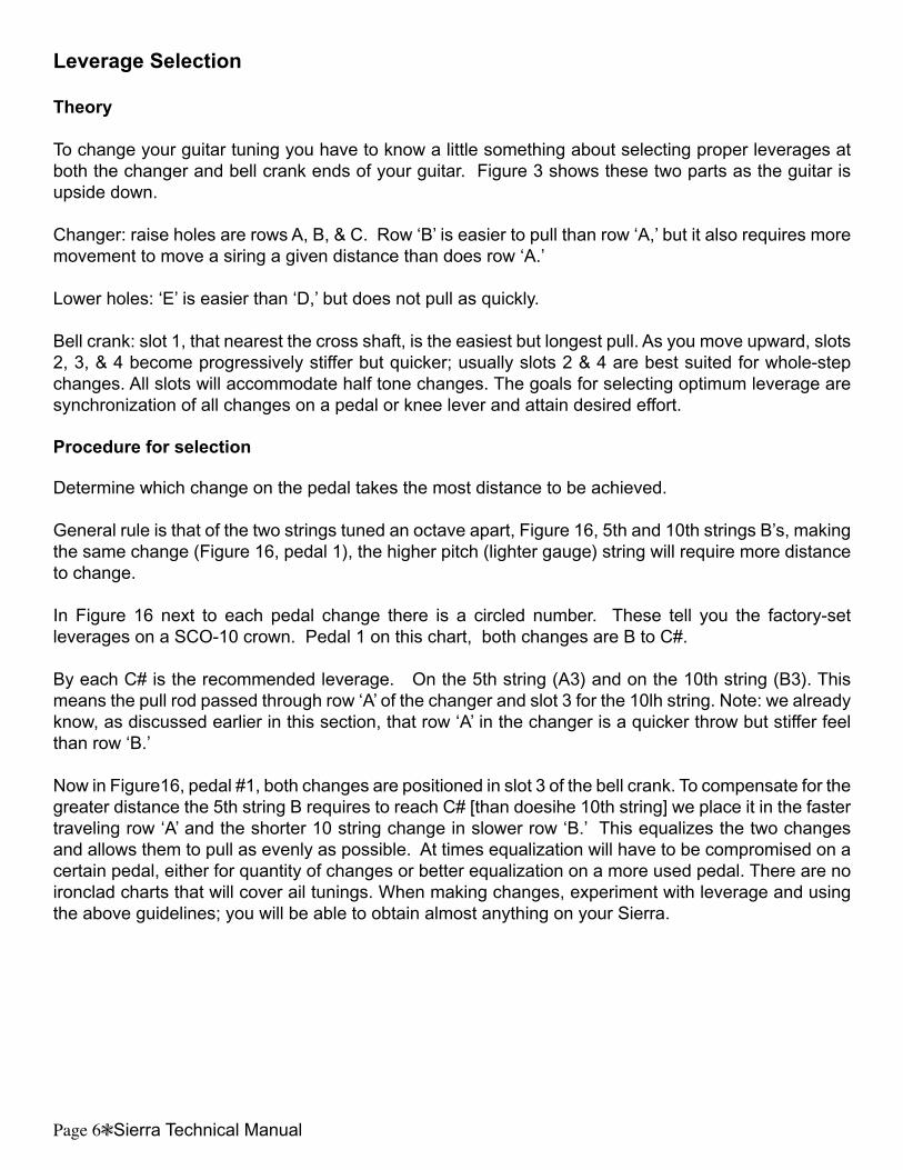
Leverage Selection
Theory
To change your guitar tuning you have to know a little something about selecting proper leverages at both the changer and bell crank ends of your guitar. Figure 3 shows these two parts as the guitar is upside down.
Changer: raise holes are rows A, B, & C. Row ‘B’ is easier to pull than row ‘A,’ but it also requires more movement to move a siring a given distance than does row ‘A.’
Lower holes: ‘E’ is easier than ‘D,’ but does not pull as quickly.
Bell crank: slot 1, that nearest the cross shaft, is the easiest but longest pull. As you move upward, slots 2, 3, & 4 become progressively stiffer but quicker; usually slots 2 & 4 are best suited for whole-step changes. All slots will accommodate half tone changes. The goals for selecting optimum leverage are synchronization of all changes on a pedal or knee lever and attain desired effort.
Procedure for selection
Determine which change on the pedal takes the most distance to be achieved.
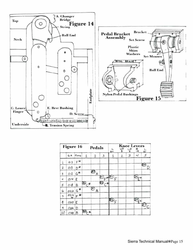
General rule is that of the two strings tuned an octave apart, Figure 16, 5th and 10th strings B’s, making the same change (Figure 16, pedal 1), the higher pitch (lighter gauge) string will require more distance to change.
In Figure 16 next to each pedal change there is a circled number. These tell you the factory-set leverages on a SCO-10 crown. Pedal 1 on this chart, both changes are B to C#.
By each C# is the recommended leverage. On the 5th string (A3) and on the 10th string (B3). This means the pull rod passed through row ‘A’ of the changer and slot 3 for the 10lh string. Note: we already know, as discussed earlier in this section, that row ‘A’ in the changer is a quicker throw but stiffer feel than row ‘B.’
Now in Figure16, pedal #1, both changes are positioned in slot 3 of the bell crank. To compensate for the greater distance the 5th string B requires to reach C# [than doesihe 10th string] we place it in the faster traveling row ‘A’ and the shorter 10 string change in slower row ‘B.’ This equalizes the two changes and allows them to pull as evenly as possible. At times equalization will have to be compromised on a certain pedal, either for quantity of changes or better equalization on a more used pedal. There are no ironclad charts that will cover ail tunings. When making changes, experiment with leverage and using the above guidelines; you will be able to obtain almost anything on your Sierra.
Page 6Sierra Technical Manual Sierra Technical ManualPage 7
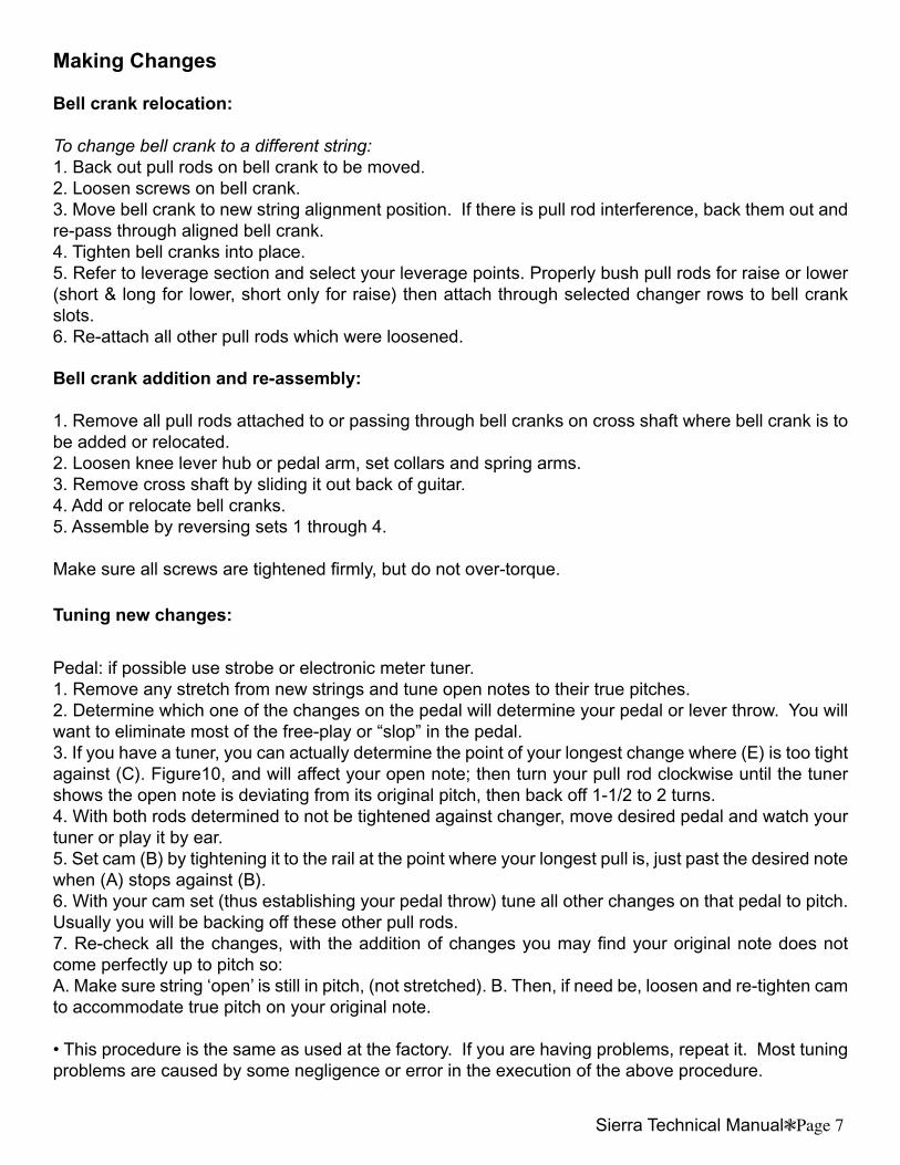
Making Changes
Bell crank relocation:
To change bell crank to a different string:1. Back out pull rods on bell crank to be moved. 2. Loosen screws on bell crank.3. Move bell crank to new string alignment position. If there is pull rod interference, back them out and re-pass through aligned bell crank.4. Tighten bell cranks into place.5. Refer to leverage section and select your leverage points. Properly bush pull rods for raise or lower (short & long for lower, short only for raise) then attach through selected changer rows to bell crank slots.6. Re-attach all other pull rods which were loosened.
Bell crank addition and re-assembly:
1. Remove all pull rods attached to or passing through bell cranks on cross shaft where bell crank is to be added or relocated.2. Loosen knee lever hub or pedal arm, set collars and spring arms.3. Remove cross shaft by sliding it out back of guitar.4. Add or relocate bell cranks.5. Assemble by reversing sets 1 through 4.
Make sure all screws are tightened firmly, but do not over-torque.
Tuning new changes:
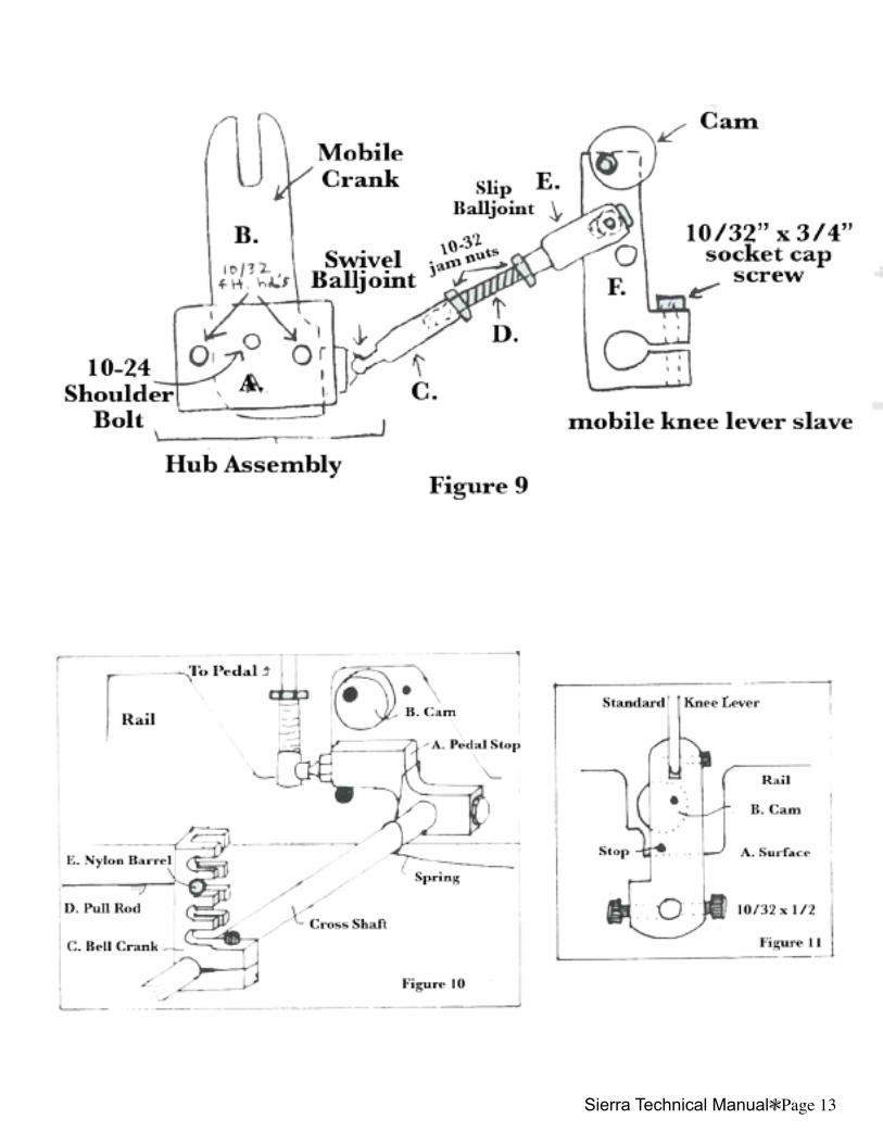
Pedal: if possible use strobe or electronic meter tuner.1. Remove any stretch from new strings and tune open notes to their true pitches.2. Determine which one of the changes on the pedal will determine your pedal or lever throw. You will want to eliminate most of the free-play or “slop” in the pedal.3. If you have a tuner, you can actually determine the point of your longest change where (E) is too tight against (C). Figure10, and will affect your open note; then turn your pull rod clockwise until the tuner shows the open note is deviating from its original pitch, then back off 1-1/2 to 2 turns.4. With both rods determined to not be tightened against changer, move desired pedal and watch your tuner or play it by ear.5. Set cam (B) by tightening it to the rail at the point where your longest pull is, just past the desired note when (A) stops against (B).6. With your cam set (thus establishing your pedal throw) tune all other changes on that pedal to pitch. Usually you will be backing off these other pull rods.7. Re-check all the changes, with the addition of changes you may find your original note does not come perfectly up to pitch so:A. Make sure string ‘open’ is still in pitch, (not stretched). B. Then, if need be, loosen and re-tighten cam to accommodate true pitch on your original note.
• This procedure is the same as used at the factory. If you are having problems, repeat it. Most tuning problems are caused by some negligence or error in the execution of the above procedure.
Page 8Sierra Technical Manual Sierra Technical ManualPage 9
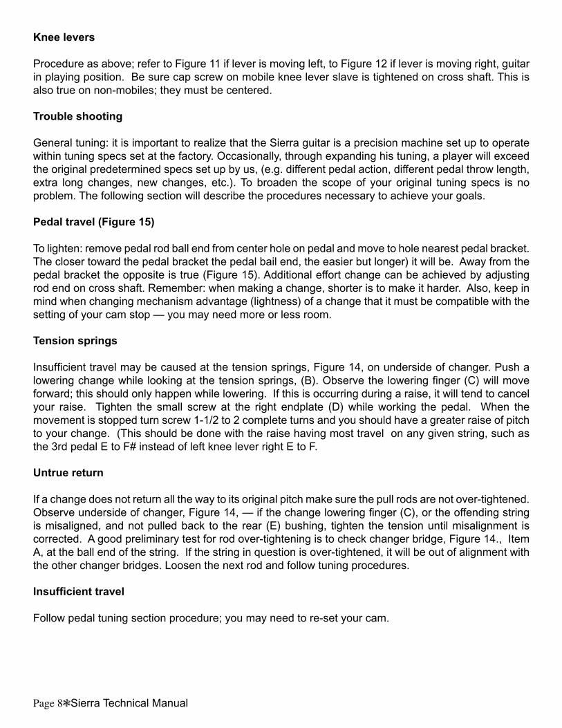
Knee levers
Procedure as above; refer to Figure 11 if lever is moving left, to Figure 12 if lever is moving right, guitar in playing position. Be sure cap screw on mobile knee lever slave is tightened on cross shaft. This is also true on non-mobiles; they must be centered.
Trouble shooting
General tuning: it is important to realize that the Sierra guitar is a precision machine set up to operate within tuning specs set at the factory. Occasionally, through expanding his tuning, a player will exceed the original predetermined specs set up by us, (e.g. different pedal action, different pedal throw length, extra long changes, new changes, etc.). To broaden the scope of your original tuning specs is no problem. The following section will describe the procedures necessary to achieve your goals.
Pedal travel (Figure 15)
To lighten: remove pedal rod ball end from center hole on pedal and move to hole nearest pedal bracket. The closer toward the pedal bracket the pedal bail end, the easier but longer) it will be. Away from the pedal bracket the opposite is true (Figure 15). Additional effort change can be achieved by adjusting rod end on cross shaft. Remember: when making a change, shorter is to make it harder. Also, keep in mind when changing mechanism advantage (lightness) of a change that it must be compatible with the setting of your cam stop — you may need more or less room.
Tension springs
Insufficient travel may be caused at the tension springs, Figure 14, on underside of changer. Push a lowering change while looking at the tension springs, (B). Observe the lowering finger (C) will move forward; this should only happen while lowering. If this is occurring during a raise, it will tend to cancel your raise. Tighten the small screw at the right endplate (D) while working the pedal. When the movement is stopped turn screw 1-1/2 to 2 complete turns and you should have a greater raise of pitch to your change. (This should be done with the raise having most travel on any given string, such as the 3rd pedal E to F# instead of left knee lever right E to F.
Untrue return
If a change does not return all the way to its original pitch make sure the pull rods are not over-tightened. Observe underside of changer, Figure 14, — if the change lowering finger (C), or the offending string is misaligned, and not pulled back to the rear (E) bushing, tighten the tension until misalignment is corrected. A good preliminary test for rod over-tightening is to check changer bridge, Figure 14., Item A, at the ball end of the string. If the string in question is over-tightened, it will be out of alignment with the other changer bridges. Loosen the next rod and follow tuning procedures.
Insufficient travel
Follow pedal tuning section procedure; you may need to re-set your cam.
Page 8Sierra Technical Manual Sierra Technical ManualPage 9
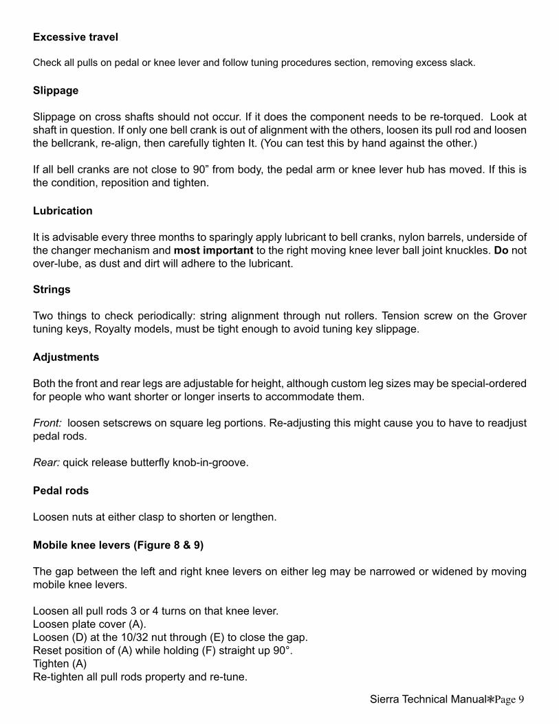
Excessive travel
Check all pulls on pedal or knee lever and follow tuning procedures section, removing excess slack.
Slippage
Slippage on cross shafts should not occur. If it does the component needs to be re-torqued. Look at shaft in question. If only one bell crank is out of alignment with the others, loosen its pull rod and loosen the bellcrank, re-align, then carefully tighten It. (You can test this by hand against the other.)
If all bell cranks are not close to 90” from body, the pedal arm or knee lever hub has moved. If this is the condition, reposition and tighten.
Lubrication
It is advisable every three months to sparingly apply lubricant to bell cranks, nylon barrels, underside of the changer mechanism and most important to the right moving knee lever ball joint knuckles. Do not over-lube, as dust and dirt will adhere to the lubricant.
Strings
Two things to check periodically: string alignment through nut rollers. Tension screw on the Grover tuning keys, Royalty models, must be tight enough to avoid tuning key slippage.
Adjustments
Both the front and rear legs are adjustable for height, although custom leg sizes may be special-ordered for people who want shorter or longer inserts to accommodate them.
Front: loosen setscrews on square leg portions. Re-adjusting this might cause you to have to readjust pedal rods.
Rear: quick release butterfly knob-in-groove.
Pedal rods
Loosen nuts at either clasp to shorten or lengthen.
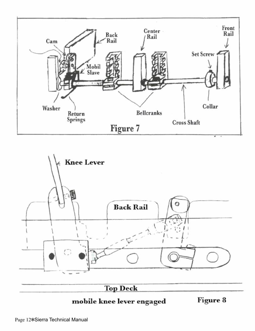
Mobile knee levers (Figure 8 & 9)
The gap between the left and right knee levers on either leg may be narrowed or widened by moving mobile knee levers.
Loosen all pull rods 3 or 4 turns on that knee lever.Loosen plate cover (A).Loosen (D) at the 10/32 nut through (E) to close the gap.Reset position of (A) while holding (F) straight up 90°.Tighten (A)Re-tighten all pull rods property and re-tune.
Page 10Sierra Technical Manual Sierra Technical ManualPage 11
Figure 1
figure 2
f3
f4
Page 10Sierra Technical Manual Sierra Technical ManualPage 11
f5
f6
Page 12Sierra Technical Manual Sierra Technical ManualPage 13
f8
Page 12Sierra Technical Manual Sierra Technical ManualPage 13
f9
f10
Page 14Sierra Technical Manual Sierra Technical ManualPage 15
f12
Page 14Sierra Technical Manual Sierra Technical ManualPage 15
f14f15
f16
Page 16Sierra Technical Manual Sierra Technical ManualPage 17
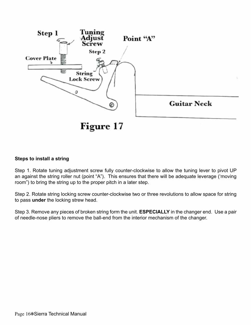
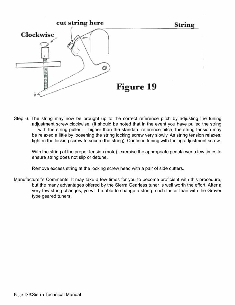
Steps to install a string
Step 1. Rotate tuning adjustment screw fully counter-clockwise to allow the tuning lever to pivot UP an against the string roller nut (point “A”). This ensures that there will be adequate leverage (‘moving room”) to bring the string up to the proper pitch in a later step.
Step 2. Rotate string locking screw counter-clockwise two or three revolutions to allow space for string to pass under the locking strew head.
Step 3. Remove any pieces of broken string form the unit. ESPECIALLY in the changer end. Use a pair of needle-nose pliers to remove the ball-end from the interior mechanism of the changer.
Page 16Sierra Technical Manual Sierra Technical ManualPage 17
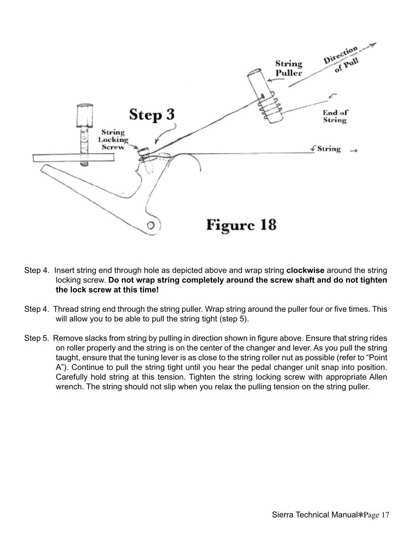
Step 4. Insert string end through hole as depicted above and wrap string clockwise around the string locking screw. Do not wrap string completely around the screw shaft and do not tighten the lock screw at this time!
Step 4. Thread string end through the string puller. Wrap string around the puller four or five times. This will allow you to be able to pull the string tight (step 5).
Step 5. Remove slacks from string by pulling in direction shown in figure above. Ensure that string rides on roller properly and the string is on the center of the changer and lever. As you pull the string taught, ensure that the tuning lever is as close to the string roller nut as possible (refer to “Point A”). Continue to pull the string tight until you hear the pedal changer unit snap into position. Carefully hold string at this tension. Tighten the string locking screw with appropriate Allen wrench. The string should not slip when you relax the pulling tension on the string puller.
Page 18Sierra Technical Manual Sierra Technical ManualPage 19
Step 6. The string may now be brought up to the correct reference pitch by adjusting the tuning adjustment screw clockwise. (It should be noted that in the event you have pulled the string — with the string puller — higher than the standard reference pitch, the string tension may be relaxed a little by loosening the string locking screw very slowly. As string tension relaxes, tighten the locking screw to secure the string). Continue tuning with tuning adjustment screw.
With the string at the proper tension (note), exercise the appropriate pedal/lever a few times to ensure string does not slip or detune.
Remove excess string at the locking screw head with a pair of side cutters.
Manufacturer’s Comments: It may take a few times for you to become proficient with this procedure, but the many advantages offered by the Sierra Gearless tuner is well worth the effort. After a very few string changes, yo will be able to change a string much faster than with the Grover type geared tuners.
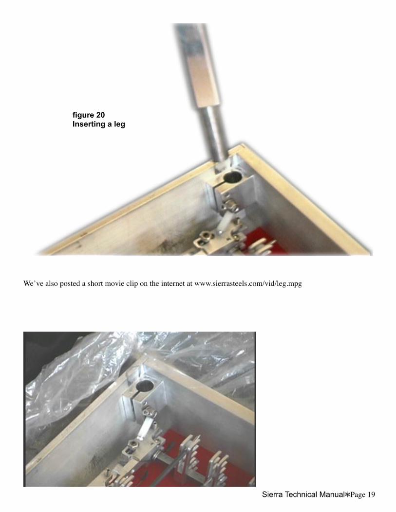
figure 20Inserting a leg
Weʼve also posted a short movie clip on the internet at www.sierrasteels.com/vid/leg.mpg
Page 18Sierra Technical Manual Sierra Technical ManualPage 19
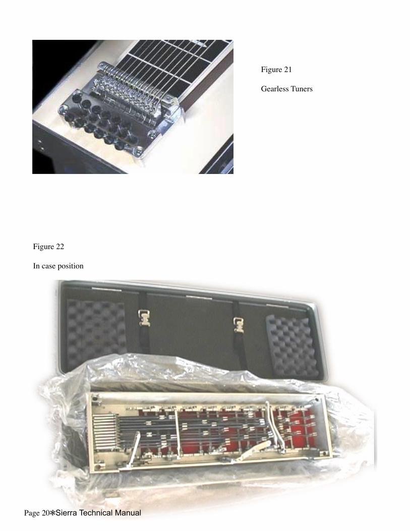
Figure 22
In case position
Figure 21
Gearless Tuners
Page 20Sierra Technical Manual


