Fluid Mechanics: Fundamentals and Applications SI Edition
Second Edition Yunus A. Çengel & John M. Cimbala
McGraw-Hill, 2010
CHAPTER 2 PROPERTIES OF FLUIDS
PROPRIETARY AND CONFIDENTIAL
This Manual is the proprietary property of The McGraw-Hill Companies, Inc. (“McGraw-Hill”) and protected by copyright and other state and federal laws. By opening and using this Manual the user agrees to the following restrictions, and if the recipient does not agree to these restrictions, the Manual should be promptly returned unopened to McGraw-Hill: This Manual is being provided only to authorized professors and instructors for use in preparing for the classes using the affiliated textbook. No other use or distribution of this Manual is permitted. This Manual may not be sold and may not be distributed to or used by any student or other third party. No part of this Manual may be reproduced, displayed or distributed in any form or by any means, electronic or otherwise, without the prior written permission of McGraw-Hill.
Density and Specific Gravity 2-1C Solution We are to define the state postulate. Analysis The state postulate is expressed as: The state of a simple compressible system is completely specified by two independent, intensive properties. Discussion An example of an intensive property is temperature.
2-2C Solution We are to discuss the difference between mass and molar mass. Analysis Mass m is the actual mass in grams or kilograms; molar mass M is the mass per mole in grams/mol or kg/kmol. These two are related to each other by m = NM, where N is the number of moles. Discussion Mass, number of moles, and molar mass are often confused. Molar mass is also called molecular weight.
2-3C Solution We are to discuss the difference between intensive and extensive properties. Analysis Intensive properties do not depend on the size (extent) of the system but extensive properties do depend on the size (extent) of the system. Discussion An example of an intensive property is temperature. An example of an extensive property is mass.
2-4C Solution We are to define specific gravity and discuss its relationship to density. Analysis The specific gravity, or relative density, is defined as the ratio of the density of a substance to the density of some standard substance at a specified temperature (the standard is water at 4°C, for which ρH2O = 1000 kg/m3). That is, H2O/ ρρ=SG . When specific gravity is known, density is determined from H2Oρρ ×= SG . Discussion Specific gravity is dimensionless and unitless [it is just a number without dimensions or units].
2-5C Solution We are to discuss the applicability of the ideal gas law. Analysis A gas can be treated as an ideal gas when it is at a high temperature and/or a low pressure relative to its critical temperature and pressure. Discussion Air and many other gases at room temperature and pressure can be approximated as ideal gases without any significant loss of accuracy.
2-6C Solution We are to discuss the difference between R and Ru. Analysis Ru is the universal gas constant that is the same for all gases, whereas R is the specific gas constant that is different for different gases. These two are related to each other by uR R / M= , where M is the molar mass (also called the molecular weight) of the gas. Discussion Since molar mass has dimensions of mass per mole, R and Ru do not have the same dimensions or units.
2-7 Solution The pressure in a container that is filled with air is to be determined. Assumptions At specified conditions, air behaves as an ideal gas.
Properties The gas constant of air is 3 3kJ kPa m kPa m0.287 0.287
kg K kJ kg KR
⎛ ⎞⋅ ⋅= =⎜ ⎟⋅ ⋅⎝ ⎠ (see also Table A-1).
Analysis The definition of the specific volume gives
/kgm 100.0kg 1
m 0.100 33
===mV
v
Using the ideal gas equation of state, the pressure is
3
3
(0.287 kPa m /kg K)(27 273.15 K) 0.100 m /kg
RTP RT P ⋅ ⋅ += → = = =vv
861 kPa
Discussion In ideal gas calculations, it saves time to convert the gas constant to appropriate units.
2-8 Solution The volume of a tank that is filled with argon at a specified state is to be determined. Assumptions At specified conditions, argon behaves as an ideal gas. Properties The gas constant of argon is obtained from Table A-1, R = 0.2081 kPa⋅m3/kg⋅K. Analysis According to the ideal gas equation of state,
3m 0.0233=+⋅⋅
==kPa 1400
K) 273K)(40/kgmkPa kg)(0.2081 (0.5 3
PmRT
V
Discussion In ideal gas calculations, it saves time to write the gas constant in appropriate units.
2-9 Solution The volume and the weight of a fluid are given. Its mass and density are to be determined. Analysis Knowing the weight, the mass and the density of the fluid are determined to be
kg 28.6=⎟⎟⎠
⎞⎜⎜⎝
⎛ ⋅==
N 1m/s kg1
m/s 9.80N 280 3
2gWm
kg/L 0.894===L 32 kg28.6
V
mρ
Discussion Note that mass is an intrinsic property, but weight is not.
2-10 Solution A balloon is filled with helium gas. The number of moles and the mass of helium are to be determined. Assumptions At specified conditions, helium behaves as an ideal gas. Properties The molar mass of helium is 4.003 kg/kmol. The temperature of the helium gas is 20oC, which we must convert to absolute temperature for use in the equations: T = 20 + 273.15 = 293.15 K. The universal gas constant is
3 3kJ kPa m kPa m8.31447 8.31447kmol K kJ kmol KuR
⎛ ⎞⋅ ⋅= =⎜ ⎟⋅ ⋅⎝ ⎠.
Analysis The volume of the sphere is
3 3 34 4 (4.5 m) 381.704 m3 3
rπ π= = =V
Assuming ideal gas behavior, the number of moles of He is determined from
3
3
(200 kPa)(381.704 m ) 31.321 kmol(8.31447 kPa m /kmol K)(293.15 K)u
PNR T
= = = ≅⋅ ⋅
V 31.3 kmol
Then the mass of He is determined from
(31.321 kmol)(4.003 kg/kmol) 125.38 kgm NM= = = ≅ 125 kg Discussion Although the helium mass may seem large (about the mass of an adult football player!), it is much smaller than that of the air it displaces, and that is why helium balloons rise in the air.
Solution A balloon is filled with helium gas. The effect of the balloon diameter on the mass of helium is to be investigated, and the results are to be tabulated and plotted.
Properties The molar mass of helium is 4.003 kg/kmol. The temperature of the helium gas is 20oC, which we must convert to absolute temperature for use in the equations: T = 20 + 273.15 = 293.15 K. The universal gas constant is
3 3kJ kPa m kPa m8.31447 8.31447kmol K kJ kmol KuR
⎛ ⎞⋅ ⋅= =⎜ ⎟⋅ ⋅⎝ ⎠.
Analysis The EES Equations window is shown below, followed by the two parametric tables and the plot (we overlaid the two cases to get them to appear on the same plot). P = 100 kPa: P = 200 kPa:
Discussion Mass increases with diameter as expected, but not linearly since volume is proportional to D3.
2-12 Solution An automobile tire is inflated with air. The pressure rise of air in the tire when the tire is heated and the amount of air that must be bled off to reduce the temperature to the original value are to be determined. Assumptions 1 At specified conditions, air behaves as an ideal gas. 2 The volume of the tire remains constant.
Properties The gas constant of air is 3 3kJ kPa m kPa m0.287 0.287
kg K kJ kg KR
⎛ ⎞⋅ ⋅= =⎜ ⎟⋅ ⋅⎝ ⎠.
Analysis Initially, the absolute pressure in the tire is
P P Pg atm1 = + = + =210 100 310 kPa
Treating air as an ideal gas and assuming the volume of the tire to remain constant, the final pressure in the tire is determined from
kPa336kPa)(310K298K323
11
22
2
22
1
11 ===⎯→⎯= PTT
PT
PT
P VV
Thus the pressure rise is
2 1 336 310P P PΔ = − = − = 26.0 kPa
The amount of air that needs to be bled off to restore pressure to its original value is
kg 0.0070=−=−=Δ
=⋅⋅
==
=⋅⋅
==
0.08360.0906
kg0.0836K)K)(323/kgmkPa(0.287
)mkPa)(0.025(310
kg0.0906K)K)(298/kgmkPa(0.287
)mkPa)(0.025(310
21
3
3
2
22
3
3
1
11
mmmRTP
m
RTP
m
V
V
Discussion Notice that absolute rather than gage pressure must be used in calculations with the ideal gas law.
2-13 Solution An automobile tire is under-inflated with air. The amount of air that needs to be added to the tire to raise its pressure to the recommended value is to be determined. Assumptions 1 At specified conditions, air behaves as an ideal gas. 2 The volume of the tire remains constant.
Properties The gas constant of air is 3 3kJ kPa m kPa m0.287 0.287
kg K kJ kg KR
⎛ ⎞⋅ ⋅= =⎜ ⎟⋅ ⋅⎝ ⎠.
Analysis The initial and final absolute pressures in the tire are
P1 = Pg1 + Patm = 140 + 100 = 240 kPa
P2 = Pg2 + Patm = 210 + 100 = 310 kPa
Treating air as an ideal gas, the initial mass in the tire is
kg 0.04140K) K)(303/kgmkPa (0.287
)m kPa)(0.015 (2403
3
1
11 =
⋅⋅==
RTP
mV
Noting that the temperature and the volume of the tire remain constant, the final mass in the tire becomes
kg 0.05347K) K)(303/kgmkPa (0.287
)m kPa)(0.015 (3103
3
2
22 =
⋅⋅==
RTP
mV
Thus the amount of air that needs to be added is kg 0.0121=−=−=Δ 0.041400.0534712 mmm Discussion Notice that absolute rather than gage pressure must be used in calculations with the ideal gas law.
2-14 Solution A rigid tank contains slightly pressurized air. The amount of air that needs to be added to the tank to raise its pressure and temperature to the recommended values is to be determined. Assumptions 1 At specified conditions, air behaves as an ideal gas. 2 The volume of the tank remains constant. Properties The gas constant of air is R = 0.287 kPa⋅m3/kg⋅K. Analysis Treating air as an ideal gas, the initial volume and the final mass in the tank are determined to be
kg 5.34
K) K)(303/kgmkPa (0.287)m kPa)(12.01 (250
m 01.12kPa 140
K) K)(293/kgmkPa kg)(0.287 (20
3
3
2
22
33
1
11
=⋅⋅
==
=⋅⋅
==
RTP
m
PRTm
V
V
Thus the amount of air added is
kg 14.5=−=−=Δ 0.02.53412 mmm Discussion As the temperature slowly decreases due to heat transfer, the pressure will also decrease.
Solution A relation for the variation of density with elevation is to be obtained, the density at 7 km elevation is to be calculated, and the mass of the atmosphere using the correlation is to be estimated. Assumptions 1 Atmospheric air behaves as an ideal gas. 2 The earth is perfectly spherical with a radius of 6377 km at sea level, and the thickness of the atmosphere is 25 km. Properties The density data are given in tabular form as a function of radius and elevation, where r = z + 6377 km:
Analysis (a) Using EES, (1) Define a trivial function “rho= a+z” in the Equation window, (2) select new parametric table from Tables, and type the data in a two-column table, (3) select Plot and plot the data, and (4) select Plot and click on curve fit to get curve fit window. Then specify 2nd order polynomial and enter/edit equation. The results are:
ρ(z) = a + bz + cz2 = 1.20252 – 0.101674z + 0.0022375z2 for the unit of kg/m3, (or, ρ(z) = (1.20252 – 0.101674z + 0.0022375z2)×109 for the unit of kg/km3)
where z is the vertical distance from the earth surface at sea level. At z = 7 km, the equation gives ρ = 0.600 kg/m3. (b) The mass of atmosphere is evaluated by integration to be
[ ]5/4/)2(3/)2(2/)2(4
)2)((4)(4)(
540
3200
200
20
20
20
2
0
20
2
0
chhcrbhcrbrahbrarhar
dzzzrrczbzadzzrczbzadVmh
z
h
zV
++++++++=
++++=+++== ∫∫∫ ==
π
ππρ
where r0 = 6377 km is the radius of the earth, h = 25 km is the thickness of the atmosphere. Also, a = 1.20252, b = -0.101674, and c = 0.0022375 are the constants in the density function. Substituting and multiplying by the factor 109 to convert the density from units of kg/km3 to kg/m3, the mass of the atmosphere is determined to be approximately
m = 5.09×10¹⁸ kg EES Solution for final result:
a = 1.2025166 b = -0.10167 c = 0.0022375 r = 6377 h = 25 m = 4*pi*(a*r^2*h+r*(2*a+b*r)*h^2/2+(a+2*b*r+c*r^2)*h^3/3+(b+2*c*r)*h^4/4+c*h^5/5)*1E+9
Discussion At 7 km, the density of the air is approximately half of its value at sea level.
Vapor Pressure and Cavitation 2-16C Solution We are to define vapor pressure and discuss its relationship to saturation pressure. Analysis The vapor pressure Pv of a pure substance is defined as the pressure exerted by a vapor in phase equilibrium with its liquid at a given temperature. In general, the pressure of a vapor or gas, whether it exists alone or in a mixture with other gases, is called the partial pressure. During phase change processes between the liquid and vapor phases of a pure substance, the saturation pressure and the vapor pressure are equivalent since the vapor is pure. Discussion Partial pressure is not necessarily equal to vapor pressure. For example, on a dry day (low relative humidity), the partial pressure of water vapor in the air is less than the vapor pressure of water. If, however, the relative humidity is 100%, the partial pressure and the vapor pressure are equal.
2-17C Solution We are to discuss whether the boiling temperature of water increases as pressure increases. Analysis Yes. The saturation temperature of a pure substance depends on pressure; in fact, it increases with pressure. The higher the pressure, the higher the saturation or boiling temperature. Discussion This fact is easily seen by looking at the saturated water property tables. Note that boiling temperature and saturation pressure at a given pressure are equivalent.
2-18C Solution We are to determine if temperature increases or remains constant when the pressure of a boiling substance increases. Analysis If the pressure of a substance increases during a boiling process, the temperature also increases since the boiling (or saturation) temperature of a pure substance depends on pressure and increases with it. Discussion We are assuming that the liquid will continue to boil. If the pressure is increased fast enough, boiling may stop until the temperature has time to reach its new (higher) boiling temperature. A pressure cooker uses this principle.
2-19C Solution We are to define and discuss cavitation. Analysis In the flow of a liquid, cavitation is the vaporization that may occur at locations where the pressure drops below the vapor pressure. The vapor bubbles collapse as they are swept away from the low pressure regions, generating highly destructive, extremely high-pressure waves. This phenomenon is a common cause for drop in performance and even the erosion of impeller blades. Discussion The word “cavitation” comes from the fact that a vapor bubble or “cavity” appears in the liquid. Not all cavitation is undesirable. It turns out that some underwater vehicles employ “super cavitation” on purpose to reduce drag.
2-20 Solution The minimum pressure in a piping system to avoid cavitation is to be determined. Properties The vapor pressure of water at 35°C is 5.63 kPa. Analysis To avoid cavitation, the pressure anywhere in the flow should not be allowed to drop below the vapor (or saturation) pressure at the given temperature. That is, kPa 5.63== °Csat@35min PP
Therefore, the pressure should be maintained above 5.63 kPa everywhere in flow. Discussion Note that the vapor pressure increases with increasing temperature, and thus the risk of cavitation is greater at higher fluid temperatures.
2-21 Solution The minimum pressure in a pump is given. It is to be determined if there is a danger of cavitation. Properties The vapor pressure of water at 20°C is 2.339 kPa. Analysis To avoid cavitation, the pressure everywhere in the flow should remain above the vapor (or saturation) pressure at the given temperature, which is
sat 20 C 2 339 kPav @P P .°= = The minimum pressure in the pump is 2 kPa, which is less than the vapor pressure. Therefore, a there is danger of cavitation in the pump. Discussion Note that the vapor pressure increases with increasing temperature, and thus there is a greater danger of cavitation at higher fluid temperatures.
2-22 Solution The minimum pressure in a pump to avoid cavitation is to be determined. Properties The vapor pressure of water at 30°C is 4.25 kPa. Analysis To avoid cavitation, the pressure anywhere in the system should not be allowed to drop below the vapor (or saturation) pressure at the given temperature. That is, kPa 4.25== °Csat@25min PP Therefore, the lowest pressure that can exist in the pump is 4.25 kPa. Discussion Note that the vapor pressure increases with increasing temperature, and thus the risk of cavitation is greater at higher fluid temperatures.
Energy and Specific Heats 2-23C Solution We are to discuss the difference between macroscopic and microscopic forms of energy. Analysis The macroscopic forms of energy are those a system possesses as a whole with respect to some outside reference frame. The microscopic forms of energy, on the other hand, are those related to the molecular structure of a system and the degree of the molecular activity, and are independent of outside reference frames. Discussion We mostly deal with macroscopic forms of energy in fluid mechanics.
2-24C Solution We are to define total energy and identify its constituents. Analysis The sum of all forms of the energy a system possesses is called total energy. In the absence of magnetic, electrical, and surface tension effects, the total energy of a system consists of the kinetic, potential, and internal energies. Discussion All three constituents of total energy (kinetic, potential, and internal) need to be considered in an analysis of a general fluid flow.
2-25C Solution We are to list the forms of energy that contribute to the internal energy of a system. Analysis The internal energy of a system is made up of sensible, latent, chemical, and nuclear energies. The sensible internal energy is due to translational, rotational, and vibrational effects. Discussion We deal with the flow of a single phase fluid in most problems in this textbook; therefore, latent, chemical, and nuclear energies do not need to be considered.
2-26C Solution We are to discuss the relationship between heat, internal energy, and thermal energy. Analysis Thermal energy is the sensible and latent forms of internal energy. It does not include chemical or nuclear forms of energy. In common terminology, thermal energy is referred to as heat. However, like work, heat is not a property, whereas thermal energy is a property. Discussion Technically speaking, “heat” is defined only when there is heat transfer, whereas the energy state of a substance can always be defined, even if no heat transfer is taking place.
2-27C Solution We are to define and discuss flow energy. Analysis Flow energy or flow work is the energy needed to push a fluid into or out of a control volume. Fluids at rest do not possess any flow energy. Discussion Flow energy is not a fundamental quantity, like kinetic or potential energy. However, it is a useful concept in fluid mechanics since fluids are often forced into and out of control volumes in practice.
2-28C Solution We are to compare the energies of flowing and non-flowing fluids. Analysis A flowing fluid possesses flow energy, which is the energy needed to push a fluid into or out of a control volume, in addition to the forms of energy possessed by a non-flowing fluid. The total energy of a non-flowing fluid consists of internal and potential energies. If the fluid is moving as a rigid body, but not flowing, it may also have kinetic energy (e.g., gasoline in a tank truck moving down the highway at constant speed with no sloshing). The total energy of a flowing fluid consists of internal, kinetic, potential, and flow energies. Discussion Flow energy is not to be confused with kinetic energy, even though both are zero when the fluid is at rest.
2-29C Solution We are to explain how changes in internal energy can be determined. Analysis Using specific heat values at the average temperature, the changes in the specific internal energy of ideal gases can be determined from Tcu avgv Δ=Δ , . For incompressible substances, cp ≅ cv ≅ c and Tcu avg Δ=Δ . Discussion If the fluid can be treated as neither incompressible nor an ideal gas, property tables must be used.
2-30C Solution We are to explain how changes in enthalpy can be determined. Analysis Using specific heat values at the average temperature, the changes in specific enthalpy of ideal gases can be determined from Tch avgp Δ=Δ , . For incompressible substances, cp ≅ cv ≅ c and PvTcPvuh avg Δ+Δ≅Δ+Δ=Δ . Discussion If the fluid can be treated as neither incompressible nor an ideal gas, property tables must be used.
Compressibility and Speed of Sound 2-31C Solution We are to discuss the coefficient of compressibility and the isothermal compressibility. Analysis The coefficient of compressibility represents the variation of pressure of a fluid with volume or density at constant temperature. Isothermal compressibility is the inverse of the coefficient of compressibility, and it represents the fractional change in volume or density corresponding to a change in pressure. Discussion The coefficient of compressibility of an ideal gas is equal to its absolute pressure.
2-32C Solution We are to define the coefficient of volume expansion. Analysis The coefficient of volume expansion represents the variation of the density of a fluid with temperature at constant pressure. It differs from the coefficient of compressibility in that the latter represents the variation of pressure of a fluid with density at constant temperature. Discussion The coefficient of volume expansion of an ideal gas is equal to the inverse of its absolute temperature.
2-33C Solution We are to discuss the sign of the coefficient of compressibility and the coefficient of volume expansion. Analysis The coefficient of compressibility of a fluid cannot be negative, but the coefficient of volume expansion can be negative (e.g., liquid water below 4°C). Discussion This is the reason that ice floats on water.
2-34 Solution The volume of an ideal gas is reduced by half at constant temperature. The change in pressure is to be determined. Assumptions The process is isothermal and thus the temperature remains constant. Analysis For an ideal gas of fixed mass undergoing an isothermal process, the ideal gas relation reduces to
12 TT
1122 VV PP= → 1122 VV PP = → 11
1
11
2
12 2
5.0PPPP ===
V
V
V
V
Therefore, the change in pressure becomes 1P=−=−=Δ 1112 2 PPPPP Discussion Note that at constant temperature, pressure and volume of an ideal gas are inversely proportional.
2-35 Solution The percent increase in the density of an ideal gas is given for a moderate pressure. The percent increase in density of the gas when compressed at a higher pressure is to be determined. Assumptions The gas behaves an ideal gas. Analysis For an ideal gas, P = ρRT and ρρ /)/( PRTP T ==∂∂ , and thus P=gas idealκ . Therefore, the coefficient of compressibility of an ideal gas is equal to its absolute pressure, and the coefficient of compressibility of the gas increases with increasing pressure.
Substituting κ = P into the definition of the coefficient of compressibility ρρ
κ// Δ
Δ≅Δ
Δ−≅ PPvv
and rearranging
gives
PPΔ=Δ
ρρ
Therefore, the percent increase of density of an ideal gas during isothermal compression is equal to the percent increase in pressure.
At 10 atm: %1010
1011 =−=Δ=ΔPP
ρρ
At 1000 atm: %1.01000
10001001 =−=Δ=ΔPP
ρρ
Therefore, a pressure change of 1 atm causes a density change of 10% at 10 atm and a density change of 1% at 100 atm. Discussion If temperature were also allowed to change, the relationship would not be so simple.
2-36 Solution Using the definition of the coefficient of volume expansion and the expression T/1gas ideal =β , it is to be shown that the percent increase in the specific volume of an ideal gas during isobaric expansion is equal to the percent increase in absolute temperature. Assumptions The gas behaves an ideal gas.
Analysis The coefficient of volume expansion β can be expressed as TT P Δ
Δ≈⎟⎠⎞
⎜⎝⎛
∂∂= vvv
v/1β .
Noting that T/1gas ideal =β for an ideal gas and rearranging give
TTΔ=Δ
vv
Therefore, the percent increase in the specific volume of an ideal gas during isobaric expansion is equal to the percent increase in absolute temperature. Discussion We must be careful to use absolute temperature (K or R), not relative temperature (oC or oF).
2-37 Solution Water at a given temperature and pressure is compressed to a high pressure isothermally. The increase in the density of water is to be determined. Assumptions 1 The isothermal compressibility is constant in the given pressure range. 2 An approximate analysis is performed by replacing differential changes by finite changes. Properties The density of water at 20°C and 1 atm pressure is ρ1 = 998 kg/m3. The isothermal compressibility of water is given to be α = 4.80 × 10⁻⁵ atm-1. Analysis When differential quantities are replaced by differences and the properties α and β are assumed to be constant, the change in density in terms of the changes in pressure and temperature is expressed approximately as
TP Δ−Δ=Δ βραρρ
The change in density due to a change of pressure from 1 atm to 550 atm at constant temperature is 3kg/m 26.3=−×=Δ=Δ − atm)1550)(kg/m 998)(atm 1080.4( 3-15Pαρρ
Discussion Note that the density of water increases from 998 to 1024.3 kg/m3 while being compressed, as expected. This problem can be solved more accurately using differential analysis when functional forms of properties are available
2-38 Solution Water at a given temperature and pressure is heated to a higher temperature at constant pressure. The change in the density of water is to be determined. Assumptions 1 The coefficient of volume expansion is constant in the given temperature range. 2 An approximate analysis is performed by replacing differential changes in quantities by finite changes. Properties The density of water at 15°C and 1 atm pressure is ρ1 = 999.1 kg/m3. The coefficient of volume expansion at the average temperature of (15+95)/2 = 55°C is β = 0.484 × 10⁻³ K-1. Analysis When differential quantities are replaced by differences and the properties α and β are assumed to be constant, the change in density in terms of the changes in pressure and temperature is expressed approximately as
TP Δ−Δ=Δ βραρρ
The change in density due to the change of temperature from 15°C to 95°C at constant pressure is 3kg/m 38.7−=−×−=Δ−=Δ − K)1595)( kg/m1.999)(K 10484.0( 3-13Tβρρ
Discussion Noting that 12 ρρρ −=Δ , the density of water at 95°C and 1 atm is
312 kg/m4.960)7.38(1.999 =−+=Δ+= ρρρ
which is very close to the listed value of 961.5 kg/m3 at 95°C in water table in the Appendix. This is mostly due to β varying with temperature almost linearly. Note that the density of water decreases while being heated, as expected. This problem can be solved more accurately using differential analysis when functional forms of properties are available.
2-39 Solution Saturated refrigerant-134a at a given temperature is cooled at constant pressure. The change in the density of the refrigerant is to be determined. Assumptions 1 The coefficient of volume expansion is constant in the given temperature range. 2 An approximate analysis is performed by replacing differential changes in quantities by finite changes. Properties The density of saturated liquid R-134a at 10°C is ρ1 =1261 kg/m3. The coefficient of volume expansion at the average temperature of (10+0)/2 = 5°C is β = 0.00269 K-1. Analysis When differential quantities are replaced by differences and the properties α and β are assumed to be constant, the change in density in terms of the changes in pressure and temperature is expressed approximately as
TP Δ−Δ=Δ βραρρ
The change in density due to the change of temperature from 10°C to 0°C at constant pressure is 3kg/m 33.9=−−=Δ−=Δ K)100)(kg/m 1261)(K 00269.0( 3-1Tβρρ
Discussion Noting that 12 ρρρ −=Δ , the density of R-134a at 0°C is
312 kg/m9.12949.331261 =+=Δ+= ρρρ
which is almost identical to the listed value of 1295 kg/m3 at 0°C in R-134a table in the Appendix. This is mostly due to β varying with temperature almost linearly. Note that the density increases during cooling, as expected.
2-40 Solution A water tank completely filled with water can withstand tension caused by a volume expansion of 1.2%. The maximum temperature rise allowed in the tank without jeopardizing safety is to be determined. Assumptions 1 The coefficient of volume expansion is constant. 2 An approximate analysis is performed by replacing differential changes in quantities by finite changes. 3 The effect of pressure is disregarded. Properties The average volume expansion coefficient is given to be β = 0.377 × 10⁻³ K-1. Analysis When differential quantities are replaced by differences and the properties α and β are assumed to be constant, the change in density in terms of the changes in pressure and temperature is expressed approximately as
TP Δ−Δ=Δ βραρρ
A volume increase of 1.2% corresponds to a density decrease of 1.2%, which can be expressed as ρρ 012.0−=Δ . Then the decrease in density due to a temperature rise of ΔT at constant pressure is
TΔ−=− βρρ012.0
Solving for ΔT and substituting, the maximum temperature rise is determined to be
C31.8K 31.8 °==×
==Δ − 1-3 K 10377.0012.0012.0
βT
Discussion This result is conservative since in reality the increasing pressure will tend to compress the water and increase its density.
2-41 Solution A water tank completely filled with water can withstand tension caused by a volume expansion of 1.5%. The maximum temperature rise allowed in the tank without jeopardizing safety is to be determined. Assumptions 1 The coefficient of volume expansion is constant. 2 An approximate analysis is performed by replacing differential changes in quantities by finite changes. 3 The effect of pressure is disregarded. Properties The average volume expansion coefficient is given to be β = 0.377 × 10⁻³ K-1. Analysis When differential quantities are replaced by differences and the properties α and β are assumed to be constant, the change in density in terms of the changes in pressure and temperature is expressed approximately as
TP Δ−Δ=Δ βραρρ
A volume increase of 1.5% corresponds to a density decrease of 1.5%, which can be expressed as ρρ 015.0−=Δ . Then the decrease in density due to a temperature rise of ΔT at constant pressure is
TΔ−=− βρρ015.0
Solving for ΔT and substituting, the maximum temperature rise is determined to be
C39.8K 39.8 °==×
==Δ − 1-3 K 10377.0015.0015.0
βT
Discussion This result is conservative since in reality the increasing pressure will tend to compress the water and increase its density. The change in temperature is exactly half of that of the previous problem, as expected.
2-42 Solution The density of seawater at the free surface and the bulk modulus of elasticity are given. The density and pressure at a depth of 2500 m are to be determined. Assumptions 1 The temperature and the bulk modulus of elasticity of seawater is constant. 2 The gravitational acceleration remains constant. Properties The density of seawater at free surface where the pressure is given to be 1030 kg/m3, and the bulk modulus of elasticity of seawater is given to be 2.34 × 10⁹ N/m2. Analysis The coefficient of compressibility or the bulk modulus of elasticity of fluids is expressed as
T
P⎟⎟⎠
⎞⎜⎜⎝
⎛∂∂=ρ
ρκ or ρ
ρκddP= (at constant T )
The differential pressure change across a differential fluid height of dz is given as
gdzdP ρ=
Combining the two relations above and rearranging,
ρ
ρρ
ρρκddzg
dgdz 2== →
κρρ gdzd =2
Integrating from z = 0 where 30 kg/m1030 == ρρ to z = z where ρρ = gives
dzgd z
∫∫ =02
0 κρρρ
ρ →
κρρgz
=− 11
0
Solving for ρ gives the variation of density with depth as
( ) ( )0
11 / gz /
ρρ κ
=−
Substituting into the pressure change relation gdzdP ρ= and integrating from z = 0 where kPa98 0 == PP to z = z where P = P gives
( ) ( )0 0
01P z
P
gdzdP/ gz /ρ κ
=−∫ ∫ →
( )00
1ln1
P Pgz /
κρ κ
⎛ ⎞= + ⎜ ⎟⎜ ⎟−⎝ ⎠
which is the desired relation for the variation of pressure in seawater with depth. At z = 2500 m, the values of density and pressure are determined by substitution to be
since 1 Pa = 1 N/m2 = 1 kg/m⋅s2 and 1 kPa = 1000 Pa. Discussion Note that if we assumed ρ = ρo = constant at 1030 kg/m3, the pressure at 2500 m would be gzPP ρ+= 0 = 0.098 + 25.26 = 25.36 MPa. Then the density at 2500 m is estimated to be
2-43 Solution The coefficient of compressibility of water is given. The pressure increases required to reduce the volume of water by 1 percent and then by 2 percent are to be determined. Assumptions 1 The coefficient of compressibility is constant. 2 The temperature remains constant. Properties The coefficient of compressibility of water is given to be 5×10⁶ kPa. Analysis (a) A volume decrease of 1 percent can mathematically be expressed as
01.0−=Δ=ΔVV
vv
The coefficient of compressibility is expressed as
vvv
v/Δ
Δ−≅⎟⎠⎞
⎜⎝⎛
∂∂−= PP
Tκ
Rearranging and substituting, the required pressure increase is determined to be
kPa 50,000=−×−=⎟⎠⎞
⎜⎝⎛ Δ−=Δ )01.0)(kPa 105( 6
vvκP
(b) Similarly, the required pressure increase for a volume reduction of 2 percent becomes
kPa 100,000=−×−=⎟⎠⎞
⎜⎝⎛ Δ−=Δ )02.0)(kPa 105( 6
vvκP
Discussion Note that at extremely high pressures are required to compress water to an appreciable amount.
2-44 Solution We are to estimate the energy required to heat up the water in a hot-water tank. Assumptions 1 There are no losses. 2 The pressure in the tank remains constant at 1 atm. 3 An approximate analysis is performed by replacing differential changes in quantities by finite changes. Properties The specific heat of water is approximated as a constant, whose value is 4.18 kJ/kg⋅K at the average temperature of (15 + 55)/2 = 35oC. The density at this temperature is 993 kg/m3 (to three digits). Analysis For a constant pressure process, avgu c TΔ ≅ Δ . Since this is energy per unit mass, we must multiply by the total mass of the water in the tank, i.e., avg avgU mc T c TρΔ ≅ Δ = ΔV . Thus,
where we note temperature differences are identical in oC and K. Discussion We give the final answer to 3 significant digits. The actual energy required will be greater than this, due to heat transfer losses and other inefficiencies in the hot-water heating system.
2-45 Solution We are to prove that the coefficient of volume expansion for an ideal gas is equal to 1/T. Assumptions 1 Temperature and pressure are in the range that the gas can be approximated as an ideal gas.
Analysis The ideal gas law is P RTρ= , which we re-write as PRT
where both pressure and the gas constant R are treated as constants in the differentiation. Discussion The coefficient of volume expansion of an ideal gas is not constant, but rather decreases with temperature. However, for small temperature differences, β is often approximated as a constant with little loss of accuracy.
2-46 Solution We are to estimate the density of air at two temperatures using the Boussinesq approximation, and we are to compare to the actual density at those temperatures. Assumptions 1 The coefficient of volume expansion is constant in the given temperature range. 2 The pressure remains constant at 95.0 kPa throughout the flow field. 3 Air is taken as an ideal gas. Properties The reference density of air at T0 = 40°C (313.15 K) and P = 95.0 kPa is
( )( )2
30
0
95.0 kPa kJ kN/m 1.05703 kg/m0.2870 kJ/kg K 313.15 kN m kPa
PRT K
ρ⎛ ⎞⎛ ⎞= = =⎜ ⎟⎜ ⎟⋅ ⋅⎝ ⎠⎝ ⎠
where we have kept 6 significant digits to avoid round-off error in subsequent calculations. The coefficient of volume expansion at at T0 = 40°C (313.15 K) is β = 1/T0 = 3.1934 × 10⁻³ K-1. Analysis Using the Boussinesq approximation at T = 20oC , we calculate
Boussinesq density at 20oC:
( )
( ) ( )( )20 0 0
3 3 -1 3
1
1.05703 kg/m 1 3.1934 10 K 20 40 K 1.1245 kg/m
T Tρ ρ β−
⎡ ⎤= − −⎣ ⎦⎡ ⎤= − × − = ≅⎣ ⎦
31.12 kg/m
where we note temperature differences are identical in oC and K. Similarly, at T = 60oC,
Boussinesq density at 60oC:
( )
( ) ( )( )60 0 0
3 3 -1 3
1
1.05703 kg/m 1 3.1934 10 K 60 40 K 0.98953 kg/m
T Tρ ρ β−
⎡ ⎤= − −⎣ ⎦⎡ ⎤= − × − = ≅⎣ ⎦
30.990 kg/m
The actual values of density are obtained from the ideal gas law, yielding ρ20, actual = 1.1292 kg/m3 ≈ 1.13 kg/m3; the Boussinesq approximation has a percentage error of -0.41%. Similarly, ρ20, actual = 0.99358 kg/m3 ≈ 0.994 kg/m3; the Boussinesq approximation has a percentage error of -0.41%. Thus, the Boussinesq approximation is extremely good for this range of temperature. Discussion In the calculation of percentage error, we used five digits of precision to avoid round-off error. Note that the density of air decreases when heated, as expected (hot air rises). The Boussinesq approximation is often used in computational fluid dynamics (CFD).
2-47C Solution We are to define and discuss sound and how it is generated and how it travels. Analysis Sound is an infinitesimally small pressure wave. It is generated by a small disturbance in a medium. It travels by wave propagation. Sound waves cannot travel in a vacuum. Discussion Electromagnetic waves, like light and radio waves, can travel in a vacuum, but sound cannot.
2-48C Solution We are to state whether the propagation of sound waves is an isentropic process. Analysis Yes, the propagation of sound waves is nearly isentropic. Because the amplitude of an ordinary sound wave is very small, and it does not cause any significant change in temperature and pressure. Discussion No process is truly isentropic, but the increase of entropy due to sound propagation is negligibly small.
2-49C Solution We are to discuss sonic velocity – specifically, whether it is constant or it changes. Analysis The sonic speed in a medium depends on the properties of the medium, and it changes as the properties of the medium change. Discussion The most common example is the change in speed of sound due to temperature change.
2-50C Solution We are to discuss whether sound travels faster in warm or cool air. Analysis Sound travels faster in warm (higher temperature) air since kRTc = . Discussion On the microscopic scale, we can imagine the air molecules moving around at higher speed in warmer air, leading to higher propagation of disturbances.
2-51C Solution We are to compare the speed of sound in air, helium, and argon. Analysis Sound travels fastest in helium, since kRTc = and helium has the highest kR value. It is about 0.40 for air, 0.35 for argon, and 3.46 for helium. Discussion We are assuming, of course, that these gases behave as ideal gases – a good approximation at room temperature.
2-52C Solution We are to compare the speed of sound in air at two different pressures, but the same temperature. Analysis Air at specified conditions will behave like an ideal gas, and the speed of sound in an ideal gas depends on temperature only. Therefore, the speed of sound is the same in both mediums. Discussion If the temperature were different, however, the speed of sound would be different.
2-53C Solution We are to examine whether the Mach number remains constant in constant-velocity flow. Analysis In general, no, because the Mach number also depends on the speed of sound in gas, which depends on the temperature of the gas. The Mach number remains constant only if the temperature and the velocity are constant. Discussion It turns out that the speed of sound is not a strong function of pressure. In fact, it is not a function of pressure at all for an ideal gas.
2-54 Solution The Mach number of an aircraft and the speed of sound in air are to be determined at two specified temperatures. Assumptions Air is an ideal gas with constant specific heats at room temperature. Properties The gas constant of air is R = 0.287 kJ/kg·K. Its specific heat ratio at room temperature is k = 1.4. Analysis (a) From the definitions of the speed of sound and the Mach number,
m/s 347=⎟⎟⎠
⎞⎜⎜⎝
⎛⋅==
kJ/kg 1s/m 1000K) K)(300kJ/kg 287.0)(4.1(
22kRTc
and 0.692===m/s 347m/s 240Ma
cV
(b) At 1000 K,
m/s 634=⎟⎟⎠
⎞⎜⎜⎝
⎛⋅==
kJ/kg 1s/m 1000K) K)(1000kJ/kg 287.0)(4.1(
22kRTc
and 0.379===m/s 634m/s 240Ma
cV
Discussion Note that a constant Mach number does not necessarily indicate constant speed. The Mach number of a rocket, for example, will be increasing even when it ascends at constant speed. Also, the specific heat ratio k changes with temperature, and the accuracy of the result at 1000 K can be improved by using the k value at that temperature (it would give k = 1.386, c = 619 m/s, and Ma = 0.388).
2-55 Solution Carbon dioxide flows through a nozzle. The inlet temperature and velocity and the exit temperature of CO2 are specified. The Mach number is to be determined at the inlet and exit of the nozzle. Assumptions 1 CO2 is an ideal gas with constant specific heats at room temperature. 2 This is a steady-flow process. Properties The gas constant of carbon dioxide is R = 0.1889 kJ/kg·K. Its constant pressure specific heat and specific heat ratio at room temperature are cp = 0.8439 kJ/kg⋅K and k = 1.288. Analysis (a) At the inlet
m/s 3.540kJ/kg 1
s/m 1000K) K)(1200kJ/kg 1889.0)(288.1(22
111 =⎟⎟⎠
⎞⎜⎜⎝
⎛⋅== RTkc
Thus,
0.0925===m/s 3.540
m/s 50Ma1
11 c
V
(b) At the exit,
m/s 0.312kJ/kg 1
s/m 1000K) K)(400kJ/kg 1889.0)(288.1(22
222 =⎟⎟⎠
⎞⎜⎜⎝
⎛⋅== RTkc
The nozzle exit velocity is determined from the steady-flow energy balance relation,
2
02
12
212
VVhh
−+−= →
2)(0
21
22
12VV
TTc p−
+−=
m/s 1163s/m 1000
kJ/kg 12
m/s) 50(K) 1200400(K)kJ/kg 8439.0(0 222
222 =⎯→⎯⎟
⎠
⎞⎜⎝
⎛−+−⋅= V
V
Thus,
3.73===m/s 312m/s 1163Ma
2
22 c
V
Discussion The specific heats and their ratio k change with temperature, and the accuracy of the results can be improved by accounting for this variation. Using EES (or another property database):
Therefore, the constant specific heat assumption results in an error of 4.5% at the inlet and 15.5% at the exit in the Mach number, which are significant.
2-56 Solution Nitrogen flows through a heat exchanger. The inlet temperature, pressure, and velocity and the exit pressure and velocity are specified. The Mach number is to be determined at the inlet and exit of the heat exchanger. Assumptions 1 N2 is an ideal gas. 2 This is a steady-flow process. 3 The potential energy change is negligible. Properties The gas constant of N2 is R = 0.2968 kJ/kg·K. Its constant pressure specific heat and specific heat ratio at room temperature are cp = 1.040 kJ/kg⋅K and k = 1.4.
Analysis m/s 9.342 kJ/kg1
s/m 1000K) K)(283 kJ/kg2968.0)(400.1(22
111 =⎟⎟⎠
⎞⎜⎜⎝
⎛⋅== RTkc
Thus,
0.292===m/s 9.342
m/s 100Ma1
11 c
V
From the energy balance on the heat exchanger,
2
)(2
12
212in
VVTTcq p−+−=
⎟⎠⎞
⎜⎝⎛−
+°−°= 22
22
2 s/m 1000 kJ/kg1
2m/s) 100(m/s) 200(C)10C)( kJ/kg.040.1( kJ/kg120 T
It yields T2 = 111°C = 384 K
m/s 399 kJ/kg1
s/m 1000K) K)(384 kJ/kg2968.0)(4.1(22
222 =⎟⎟⎠
⎞⎜⎜⎝
⎛⋅== RTkc
Thus,
0.501===m/s 399m/s 200Ma
2
22 c
V
Discussion The specific heats and their ratio k change with temperature, and the accuracy of the results can be improved by accounting for this variation. Using EES (or another property database):
Therefore, the constant specific heat assumption results in an error of 4.5% at the inlet and 15.5% at the exit in the Mach number, which are almost identical to the values obtained assuming constant specific heats.
2-57 Solution The speed of sound in refrigerant-134a at a specified state is to be determined. Assumptions R-134a is an ideal gas with constant specific heats at room temperature. Properties The gas constant of R-134a is R = 0.08149 kJ/kg·K. Its specific heat ratio at room temperature is k = 1.108. Analysis From the ideal-gas speed of sound relation,
m/s 173=⎟⎟⎠
⎞⎜⎜⎝
⎛+⋅==
kJ/kg1s/m 1000K) 273K)(60 kJ/kg08149.0)(108.1(
22kRTc
Discussion Note that the speed of sound is independent of pressure for ideal gases.
2-58 Solution The Mach number of a passenger plane for specified limiting operating conditions is to be determined. Assumptions Air is an ideal gas with constant specific heats at room temperature. Properties The gas constant of air is R = 0.287 kJ/kg·K. Its specific heat ratio at room temperature is k = 1.4. Analysis From the speed of sound relation
m/s 293 kJ/kg1
s/m 1000K) 273K)(-60 kJ/kg287.0)(4.1(22
=⎟⎟⎠
⎞⎜⎜⎝
⎛+⋅== kRTc
Thus, the Mach number corresponding to the maximum cruising speed of the plane is
0.897===m/s 293
m/s )6.3/945(Ma max
cV
Discussion Note that this is a subsonic flight since Ma < 1. Also, using a k value at -60°C would give practically the same result.
2-59 Solution Steam flows through a device at a specified state and velocity. The Mach number of steam is to be determined assuming ideal gas behavior. Assumptions Steam is an ideal gas with constant specific heats. Properties The gas constant of steam is R = 0.4615 kJ/kg·K. Its specific heat ratio is given to be k = 1.3. Analysis From the ideal-gas speed of sound relation,
m/s 4.635kJ/kg 1
s/m 1000K) K)(673kJ/kg 4615.0)(3.1(22
=⎟⎟⎠
⎞⎜⎜⎝
⎛⋅== kRTc
Thus,
0.433===m/s 4.635
m/s 275MacV
Discussion Using property data from steam tables and not assuming ideal gas behavior, it can be shown that the Mach number in steam at the specified state is 0.437, which is sufficiently close to the ideal-gas value of 0.443. Therefore, the ideal gas approximation is a reasonable one in this case.
Solution Problem 2-59 is reconsidered. The variation of Mach number with temperature as the temperature changes between 200° and 400°C is to be investigated, and the results are to be plotted. Analysis The EES Equations window is printed below, along with the tabulated and plotted results. T=Temperature+273 R=0.4615 V=275 k=1.3 c=SQRT(k*R*T*1000) Ma=V/c
2-61 Solution The expression for the speed of sound for an ideal gas is to be obtained using the isentropic process equation and the definition of the speed of sound. Analysis The isentropic relation Pvk = A where A is a constant can also be expressed as
kk
Av
AP ρ=⎟⎠⎞
⎜⎝⎛= 1
Substituting it into the relation for the speed of sound,
kRTPkAkkAAPc kk
s
k
s
====⎟⎟⎠
⎞⎜⎜⎝
⎛=⎟⎟
⎠
⎞⎜⎜⎝
⎛= − )/(/)()( 12 ρρρρ
∂ρρ∂
∂ρ∂
since for an ideal gas P = ρRT or RT = P/ρ. Therefore, kRTc = , which is the desired relation.
Discussion Notice that pressure has dropped out; the speed of sound in an ideal gas is not a function of pressure.
2-62 Solution The inlet state and the exit pressure of air are given for an isentropic expansion process. The ratio of the initial to the final speed of sound is to be determined. Assumptions Air is an ideal gas with constant specific heats at room temperature. Properties The properties of air are R = 0.287 kJ/kg·K and k = 1.4. The specific heat ratio k varies with temperature, but in our case this change is very small and can be disregarded. Analysis The final temperature of air is determined from the isentropic relation of ideal gases,
K 4.228MPa 1.5MPa 0.4K) 2.333(
4.1/)14.1(/)1(
1
212 =⎟
⎠⎞
⎜⎝⎛=⎟⎟
⎠
⎞⎜⎜⎝
⎛=
−− kk
PP
TT
Treating k as a constant, the ratio of the initial to the final speed of sound can be expressed as
1.21=====4.2282.333Ratio
2
1
22
11
1
2
T
T
RTk
RTkcc
Discussion Note that the speed of sound is proportional to the square root of thermodynamic temperature.
2-63 Solution The inlet state and the exit pressure of helium are given for an isentropic expansion process. The ratio of the initial to the final speed of sound is to be determined. Assumptions Helium is an ideal gas with constant specific heats at room temperature. Properties The properties of helium are R = 2.0769 kJ/kg·K and k = 1.667. Analysis The final temperature of helium is determined from the isentropic relation of ideal gases,
K 3.1961.50.4K) 2.333(
667.1/)1667.1(/)1(
1
212 =⎟
⎠⎞
⎜⎝⎛=⎟⎟
⎠
⎞⎜⎜⎝
⎛=
−− kk
PP
TT
The ratio of the initial to the final speed of sound can be expressed as
1.30=====3.1962.333Ratio
2
1
22
11
1
2
T
T
RTk
RTkcc
Discussion Note that the speed of sound is proportional to the square root of thermodynamic temperature.
Viscosity 2-64C Solution We are to define and discuss viscosity. Analysis Viscosity is a measure of the “stickiness” or “resistance to deformation” of a fluid. It is due to the internal frictional force that develops between different layers of fluids as they are forced to move relative to each other. Viscosity is caused by the cohesive forces between the molecules in liquids, and by the molecular collisions in gases. In general, liquids have higher dynamic viscosities than gases. Discussion The ratio of viscosity μ to density ρ often appears in the equations of fluid mechanics, and is defined as the kinematic viscosity, ν = μ /ρ.
2-65C Solution We are to discuss Newtonian fluids. Analysis Fluids whose shear stress is linearly proportional to the velocity gradient (shear strain) are called Newtonian fluids. Most common fluids such as water, air, gasoline, and oils are Newtonian fluids. Discussion In the differential analysis of fluid flow, only Newtonian fluids are considered in this textbook.
2-66C Solution We are to compare the settling speed of balls dropped in water and oil; namely, we are to determine which will reach the bottom of the container first. Analysis When two identical small glass balls are dropped into two identical containers, one filled with water and the other with oil, the ball dropped in water will reach the bottom of the container first because of the much lower viscosity of water relative to oil. Discussion Oil is very viscous, with typical values of viscosity approximately 800 times greater than that of water at room temperature.
2-67C Solution We are to discuss how dynamic viscosity varies with temperature in liquids and gases. Analysis (a) The dynamic viscosity of liquids decreases with temperature. (b) The dynamic viscosity of gases increases with temperature. Discussion A good way to remember this is that a car engine is much harder to start in the winter because the oil in the engine has a higher viscosity at low temperatures.
2-68C Solution We are to discuss how kinematic viscosity varies with temperature in liquids and gases. Analysis (a) For liquids, the kinematic viscosity decreases with temperature. (b) For gases, the kinematic viscosity increases with temperature. Discussion You can easily verify this by looking at the appendices.
2-69 Solution For flow over a plate, the variation of velocity with distance is given. A relation for the wall shear stress is to be obtained. Assumptions The fluid is Newtonian. Analysis Noting that u(y) = ay – by2, wall shear stress is determined from its definition to be
aμ=−=−
== ===
00
2
0
)2()(y
yyw bya
dybyayddu μμμτ
dy
Discussion Note that shear stress varies with vertical distance in this case.
2-70 Solution A block is moved at constant velocity on an inclined surface. The force that needs to be applied in the horizontal direction when the block is dry, and the percent reduction in the required force when an oil film is applied on the surface are to be determined. Assumptions 1 The inclined surface is plane (perfectly flat, although tilted). 2 The friction coefficient and the oil film thickness are uniform. 3 The weight of the oil layer is negligible. Properties The absolute viscosity of oil is given to be μ = 0.012 Pa⋅s = 0.012 N⋅s/m2. Analysis (a) The velocity of the block is constant, and thus its acceleration and the net force acting on it are zero. A free body diagram of the block is given. Then the force balance gives
:0=∑ xF 020sin20cos 11 =°−°− Nf FFF (1)
:0=∑ yF 020sin20cos1 =−°−° WFF fN (2)
Friction force: 1Nf fFF = (3)
Substituting Eq. (3) into Eq. (2) and solving for FN1 gives
N 0.17720sin27.020cos
N 15020sin20cos1 =
°−°=
°−°=
fWFN
Then from Eq. (1): N 105.5=°+°×=°+°= 20sin)N 177(20cos)N 17727.0(20sin20cos 11 Nf FFF (b) In this case, the friction force is replaced by the shear force applied on the bottom surface of the block due to the oil. Because of the no-slip condition, the oil film sticks to the inclined surface at the bottom and the lower surface of the block at the top. Then the shear force is expressed as
( )( )2 2-4
0 8 m/s 0 012 N s/m 0 5 0 2 m4 10 m
2 4 N
shear w s
s
F AVAh
.. . .
.
τ
μ
=
=
= ⋅ ××
=
Replacing the friction force by the shear force in part (a),
:0=∑ xF 020sin20cos 22 =°−°− Nshear FFF (4)
:0=∑ yF 020sin20cos2 =−°−° WFF shearN (5)
Eq. (5) gives N 60.5120cos/)]N 150(20sin)N 4.2[(20cos/)20sin(2 =°+°=°+°= WFF shearN Substituting into Eq. (4), the required horizontal force is determined to be
N 57.220sin)N 5.160(20cos)N 4.2(20sin20cos 22 =°+°=°+°= Nshear FFF Then, our final result is expressed as
Percentage reduction in required force = 1 2
1
105 5 57 2100% 100%105 5
F F . .F .− −× = × = 45.8%
Discussion Note that the force required to push the block on the inclined surface reduces significantly by oiling the surface.
Solution The velocity profile of a fluid flowing though a circular pipe is given. The friction drag force exerted on the pipe by the fluid in the flow direction per unit length of the pipe is to be determined. Assumptions The viscosity of the fluid is constant. Analysis The wall shear stress is determined from its definition to be
Run
Rnru
Rr
drdu
drdu
Rrn
n
Rrn
n
Rrw
max1
maxmax 1μ
μμμτ =−−=⎟⎟⎠
⎞⎜⎜⎝
⎛−−=−=
=
−
==
Note that the quantity du /dr is negative in pipe flow, and the negative sign is added to the τw relation for pipes to make shear stress in the positive (flow) direction a positive quantity. (Or, du /dr = - du /dy since y = R – r). Then the friction drag force exerted by the fluid on the inner surface of the pipe becomes
LunLRRun
AF ww maxmax 2)2( πμπ
μτ ===
Therefore, the drag force per unit length of the pipe is
max2/ unLF πμ= .
Discussion Note that the drag force acting on the pipe in this case is independent of the pipe diameter.
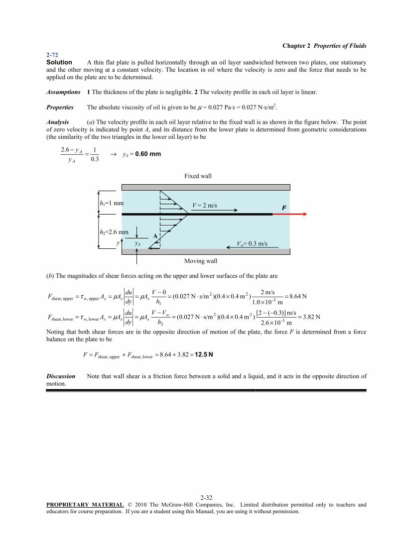
2-72 Solution A thin flat plate is pulled horizontally through an oil layer sandwiched between two plates, one stationary and the other moving at a constant velocity. The location in oil where the velocity is zero and the force that needs to be applied on the plate are to be determined. Assumptions 1 The thickness of the plate is negligible. 2 The velocity profile in each oil layer is linear. Properties The absolute viscosity of oil is given to be μ = 0.027 Pa⋅s = 0.027 N⋅s/m2. Analysis (a) The velocity profile in each oil layer relative to the fixed wall is as shown in the figure below. The point of zero velocity is indicated by point A, and its distance from the lower plate is determined from geometric considerations (the similarity of the two triangles in the lower oil layer) to be
3.0
16.2=
−
A
A
yy
→ yA = 0.60 mm
(b) The magnitudes of shear forces acting on the upper and lower surfaces of the plate are
N 64.8m 101.0
m/s 2)m 4.04.0)(s/mN 027.0(03-
22
1upper ,upper shear, =
××⋅=−===
hVA
dyduAAF sssw μμτ
N 82.3m 102.6m/s )]3.0(2[)m 4.04.0)(s/mN 027.0( 3-
22
2lower ,lower shear, =
×−−×⋅=
−===
hVV
AdyduAAF w
sssw μμτ
Noting that both shear forces are in the opposite direction of motion of the plate, the force F is determined from a force balance on the plate to be N 12.5=+=+= 82.364.8lower shear,upper shear, FFF
Discussion Note that wall shear is a friction force between a solid and a liquid, and it acts in the opposite direction of motion.
2-73 Solution A frustum shaped body is rotating at a constant angular speed in an oil container. The power required to maintain this motion and the reduction in the required power input when the oil temperature rises are to be determined.
Assumptions The thickness of the oil layer remains constant.
Properties The absolute viscosity of oil is given to be μ = 0.1 Pa⋅s = 0.1 N⋅s/m2 at 20°C and 0.0078 Pa⋅s at 80°C.
Analysis The velocity gradient anywhere in the oil of film thickness h is V/h where V = ωr is the tangential velocity. Then the wall shear stress anywhere on the surface of the frustum at a distance r from the axis of rotation is
hr
hV
drdu
wωμμμτ ===
The shear force acting on differential area dA on the surface, the torque it generates, and the shaft power associated with it are expressed as
dAhrdAdF w
ωμτ == dAhrrdFd
2T ωμ==
dArh A∫= 2T μω dAr
hW
A∫== 22
sh T μωω&
Top surface: For the top surface, rdrdA π2= . Substituting and integrating,
hDr
hdrr
hdrrr
hW
D
r
D
r
D
r 32422)2(
422/
0
4232/
0
222/
0
2
topsh,πμωπμωπμωπμω ====
=== ∫∫&
Bottom surface: A relation for the bottom surface is obtained by replacing D by d, hdW
32
42
bottomsh,πμω=&
Side surface: The differential area for the side surface can be expressed as rdzdA π2= . From geometric considerations, the
variation of radius with axial distance is expressed as zL
dDdr22−+= .
Differentiating gives dzL
dDdr2−= or dr
dDLdz−
= 2 . Therefore, rdrdD
LdzdA−
== ππ 42 . Substituting and integrating,
)(16
)(4)(
4)(
44 2222/
2/
4232/
2/
222/
0
2
topsh, dDhdDLr
dDhLdrr
dDhLrdr
dDLr
hW
D
dr
D
dr
D
r −−
=−
=−
=−
==
== ∫∫πμωπμωπμωπμω&
Then the total power required becomes
⎥⎦
⎤⎢⎣
⎡
−−
++=++=dDDdLDd
hDWWWW )])/(1[2)/(1
32
44
42
side sh, bottomsh, topsh, totalsh,πμω&&&& ,
where d/D = 4/12 = 1/3. Substituting,
W270=⎟⎠⎞
⎜⎝⎛
⎥⎥⎦
⎤
⎢⎢⎣
⎡
−−
++⋅
=Nm/s 1 W1
m )04.012.0()])3/1(1[m) 12.0(2)3/1(1
m) 0012.0(32m) 12.0( /s)200)(s/mN 1.0( 4
4422
totalsh,πW&
Noting that power is proportional to viscosity, the power required at 80°C is
W21.1 W)270(s/mN 1.0
s/mN 0078.02
2
C20 total,sh,20
80C80 total,sh, =
⋅⋅== °
°
°° WW
C
C &&μμ
Therefore, the reduction in the requires power input at 80°C is sh, total, 20 C sh, total, 80 CReduction 270 21 1W W .° °= − = − =& & 249 W , which is about 92%. Discussion Note that the power required to overcome shear forces in a viscous fluid greatly depends on temperature
2-74 Solution A clutch system is used to transmit torque through an oil film between two identical disks. For specified rotational speeds, the transmitted torque is to be determined. Assumptions 1 The thickness of the oil film is uniform. 2 The rotational speeds of the disks remain constant. Properties The absolute viscosity of oil is given to be μ = 0.38 N⋅s/m2. Analysis The disks are rotting in the same direction at different angular speeds of ω1 and of ω2 . Therefore, we can assume one of the disks to be stationary and the other to be rotating at an angular speed of 21 ωω − . The velocity gradient anywhere in the oil of film thickness h is V /h where rV )( 21 ωω −= is the tangential velocity. Then the wall shear stress anywhere on the surface of the faster disk at a distance r from the axis of rotation can be expressed as
h
rhV
drdu
w)( 21 ωωμμμτ −
===
Then the shear force acting on a differential area dA on the surface and the torque generation associated with it can be expressed as
drrh
rdAdF w )2(
)( 21 πωωμτ −==
drrh
drrh
rrdFd 321
221 )(2
)2()(
Tωωπμπωωμ −
=−
==
Integrating,
hDr
hdrr
h
D
r
D
r 32)(
4)(2)(2
T4
212/
0
42132/
0
21 ωωπμωωπμωωπμ −=
−=
−=
==∫
Noting that 2 nω π= & , the relative angular speed is
Substituting, the torque transmitted is determined to be
mN 0.82 ⋅=⋅=m) 002.0(32
m) 30.0( /s)445.5)(s/mN 38.0(T42π
Discussion Note that the torque transmitted is proportional to the fourth power of disk diameter, and is inversely proportional to the thickness of the oil film.
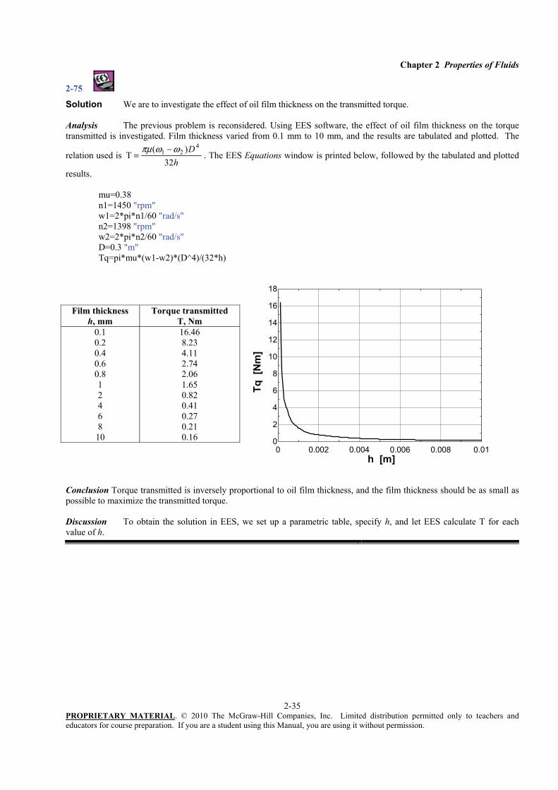
Solution We are to investigate the effect of oil film thickness on the transmitted torque. Analysis The previous problem is reconsidered. Using EES software, the effect of oil film thickness on the torque transmitted is investigated. Film thickness varied from 0.1 mm to 10 mm, and the results are tabulated and plotted. The
relation used is h
D32
)(T
421 ωωπμ −
= . The EES Equations window is printed below, followed by the tabulated and plotted
Conclusion Torque transmitted is inversely proportional to oil film thickness, and the film thickness should be as small as possible to maximize the transmitted torque. Discussion To obtain the solution in EES, we set up a parametric table, specify h, and let EES calculate T for each value of h.
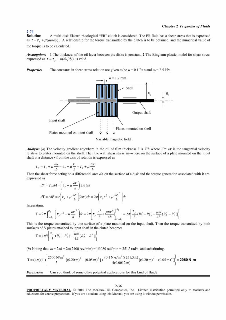
2-76 Solution A multi-disk Electro-rheological “ER” clutch is considered. The ER fluid has a shear stress that is expressed as )( dyduy μττ += . A relationship for the torque transmitted by the clutch is to be obtained, and the numerical value of the torque is to be calculated. Assumptions 1 The thickness of the oil layer between the disks is constant. 2 The Bingham plastic model for shear stress expressed as )( dyduy μττ += is valid. Properties The constants in shear stress relation are given to be μ = 0.1 Pa⋅s and τy = 2.5 kPa.
Analysis (a) The velocity gradient anywhere in the oil of film thickness h is V/h where V = ωr is the tangential velocity relative to plates mounted on the shell. Then the wall shear stress anywhere on the surface of a plate mounted on the input shaft at a distance r from the axis of rotation is expressed as
hr
hV
drdu
yyywωμτμτμττ +=+=+=
Then the shear force acting on a differential area dA on the surface of a disk and the torque generation associated with it are expressed as
drrhrdAdF yw )2( πωμττ ⎟⎠⎞
⎜⎝⎛ +==
drhrrdrr
hrrrdFd yy ⎟⎟
⎠
⎞⎜⎜⎝
⎛+=⎟
⎠⎞
⎜⎝⎛ +==
322)2(T ωμτππωμτ
Integrating,
⎥⎦
⎤⎢⎣
⎡−+−=⎥
⎦
⎤⎢⎣
⎡+=⎟⎟
⎠
⎞⎜⎜⎝
⎛+=
==∫ )(
4)(
32
4322T 4
142
31
32
4332
2
1
2
1
RRh
RRhrrdr
hrr y
R
Rryy
R
Rr
μωτπμωτπωμτπ
This is the torque transmitted by one surface of a plate mounted on the input shaft. Then the torque transmitted by both surfaces of N plates attached to input shaft in the clutch becomes
⎥⎦
⎤⎢⎣
⎡−+−= )(
4)(
34T 4
142
31
32 RR
hRRN y μωτ
π
(b) Noting that rad/s3.251 rad/min080,15) rev/min2400(22 ==== ππω n& and substituting,
mN 2060 ⋅=⎥⎦
⎤⎢⎣
⎡−
⋅+−= ])m 05.0(m) 20.0[(
m) 0012.0(4/s) 3.251)(s/mN 1.0(])m 05.0(m) 20.0[(
3N/m 2500)11)(4(T 44
233
2π
Discussion Can you think of some other potential applications for this kind of fluid?
Output shaft
Input shaft
Plates mounted on shellPlates mounted on input shaft
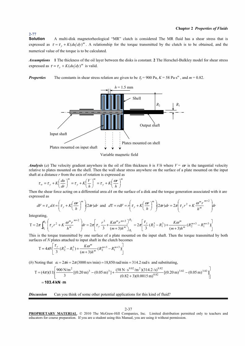
2-77 Solution A multi-disk magnetorheological “MR” clutch is considered The MR fluid has a shear stress that is expressed as m
y dyduK )(+= ττ . A relationship for the torque transmitted by the clutch is to be obtained, and the numerical value of the torque is to be calculated. Assumptions 1 The thickness of the oil layer between the disks is constant. 2 The Herschel-Bulkley model for shear stress expressed as m
y dyduK )(+= ττ is valid. Properties The constants in shear stress relation are given to be τy = 900 Pa, K = 58 Pa⋅sm , and m = 0.82. Analysis (a) The velocity gradient anywhere in the oil of film thickness h is V/h where V = ωr is the tangential velocity relative to plates mounted on the shell. Then the wall shear stress anywhere on the surface of a plate mounted on the input shaft at a distance r from the axis of rotation is expressed as
m
y
m
y
m
yw hrK
hVK
drduK ⎟
⎠⎞
⎜⎝⎛+=⎟
⎠⎞
⎜⎝⎛+=⎟
⎠⎞
⎜⎝⎛+= ωττττ
Then the shear force acting on a differential area dA on the surface of a disk and the torque generation associated with it are expressed as
drrhrKdAdF
m
yw )2( πωττ ⎟⎟⎠
⎞⎜⎜⎝
⎛⎟⎠⎞
⎜⎝⎛+== and dr
hrKrdrr
hrKrrdFd
m
m
m
y
m
y ⎟⎟
⎠
⎞
⎜⎜
⎝
⎛+=⎟
⎟⎠
⎞⎜⎜⎝
⎛⎟⎠⎞
⎜⎝⎛+==
+222)2(T ωτππωτ
Integrating,
⎥⎦
⎤⎢⎣
⎡−
++−=⎥
⎦
⎤⎢⎣
⎡
++=
⎟⎟
⎠
⎞
⎜⎜
⎝
⎛+= ++
++
∫ )()3(
)(3
2)3(3
22T 31
32
31
32
3322
2
1
2
1
mmm
my
R
Rm
mm
y
m
m
m
yR
RRR
hmKRR
hmrKrdr
hrKr ωτ
πωτπωτπ
This is the torque transmitted by one surface of a plate mounted on the input shaft. Then the torque transmitted by both surfaces of N plates attached to input shaft in the clutch becomes
⎥⎦
⎤⎢⎣
⎡−
++−= ++ )(
)3()(
34T 3
13
231
32
mmm
my RR
hmKRRN ωτ
π
(b) Noting that rad/s 2.314rad/min 850,18)rev/min 3000(22 ==== ππω n& and substituting,
2-78 Solution The torque and the rpm of a double cylinder viscometer are given. The viscosity of the fluid is to be determined. Assumptions 1 The inner cylinder is completely submerged in oil. 2 The viscous effects on the two ends of the inner cylinder are negligible. 3 The fluid is Newtonian. Analysis Substituting the given values, the viscosity of the fluid is determined to be
2s/mN 0.0128 ⋅=⋅==m) 75.0)(s 60/300(m) 075.0(4
m) m)(0.001N 8.0(4 1-3232 ππ
μLnR &
lT
Discussion This is the viscosity value at the temperature that existed during the experiment. Viscosity is a strong function of temperature, and the values can be significantly different at different temperatures.
2-79 Solution The velocity profile for laminar one-dimensional flow through a circular pipe is given. A relation for friction drag force exerted on the pipe and its numerical value for water are to be determined. Assumptions 1 The flow through the circular pipe is one-dimensional. 2 The fluid is Newtonian. Properties The viscosity of water at 20°C is given to be 0.0010 kg/m⋅s.
Analysis (a) The velocity profile is given by ⎟⎟⎠
⎞⎜⎜⎝
⎛−= 2
2
max 1)(Rruru
where R is the radius of the pipe, r is the radial distance from the center of the pipe, and umax is the maximum flow velocity, which occurs at the center, r = 0. The shear stress at the pipe surface is expressed as
Ru
Rru
Rr
drdu
drdu
RrRrRrw
max2max2
2
max221
μμμμτ =−−=⎟⎟
⎠
⎞⎜⎜⎝
⎛−−=−=
===
Note that the quantity du/dr is negative in pipe flow, and the negative sign is added to the τw relation for pipes to make shear stress in the positive (flow) direction a positive quantity. (Or, du/dr = −du/dy since y = R – r). Then the friction drag force exerted by the fluid on the inner surface of the pipe becomes
max2 (2 )D w suF A RLR
μτ π= = = max4πμLu
(b) Substituting the values we get N 1.13=⎟⎟⎠
⎞⎜⎜⎝
⎛
⋅⋅== 2max m/skg 1
N 1m/s) m)(3 s)(30kg/m 0010.0(44 ππμLuFD
Discussion In the entrance region and during turbulent flow, the velocity gradient is greater near the wall, and thus the drag force in such cases will be greater.
2-80 Solution The velocity profile for laminar one-dimensional flow through a circular pipe is given. A relation for friction drag force exerted on the pipe and its numerical value for water are to be determined. Assumptions 1 The flow through the circular pipe is one-dimensional. 2 The fluid is Newtonian. Properties The viscosity of water at 20°C is given to be 0.0010 kg/m⋅s.
Analysis (a) The velocity profile is given by ⎟⎟⎠
⎞⎜⎜⎝
⎛−= 2
2
max 1)(Rruru
where R is the radius of the pipe, r is the radial distance from the center of the pipe, and umax is the maximum flow velocity, which occurs at the center, r = 0. The shear stress at the pipe surface can be expressed as
Ru
Rru
Rr
drdu
drdu
RrRrRrw
max2max2
2
max221
μμμμτ =−−=⎟⎟
⎠
⎞⎜⎜⎝
⎛−−=−=
===
Note that the quantity du/dr is negative in pipe flow, and the negative sign is added to the τw relation for pipes to make shear stress in the positive (flow) direction a positive quantity. (Or, du/dr = −du/dy since y = R – r). Then the friction drag force exerted by the fluid on the inner surface of the pipe becomes
Discussion In the entrance region and during turbulent flow, the velocity gradient is greater near the wall, and thus the drag force in such cases will be larger.
2-81 Solution A thin flat plate is pulled horizontally through the mid plane of an oil layer sandwiched between two stationary plates. The force that needs to be applied on the plate to maintain this motion is to be determined for this case and for the case when the plate . Assumptions 1 The thickness of the plate is negligible. 2 The velocity profile in each oil layer is linear. Properties The absolute viscosity of oil is given to be μ = 0.9 N⋅s/m2. Analysis The velocity profile in each oil layer relative to the fixed wall is as shown in the figure.
The magnitudes of shear forces acting on the upper and lower surfaces of the moving thin plate are
N 225m 0.02
m/s 5)m 25.0)(s/mN 9.0(0 22
1 upper, uppershear, =×⋅=−===
hVA
dyduAAF sssw μμτ
N 225m 0.02
m/s 5)m 25.0)(s/mN 9.0( 22
2lower ,lower shear, =×⋅=
−===
hVV
AdyduAAF w
sssw μμτ
Noting that both shear forces are in the opposite direction of motion of the plate, the force F is determined from a force balance on the plate to be N 450=+=+= 225225lower shear, uppershear, FFF
When the plate is 1 cm from the bottom surface and 3 cm from the top surface, the force F becomes
N 150m 0.03
m/s 5)m 25.0)(s/mN 9.0(0 22
1 upper, uppershear, =×⋅=−===
hVA
dyduAAF sssw μμτ
N 450m 0.01
m/s 5)m 25.0)(s/mN 9.0(0 22
2lower ,lower shear, =×⋅=−===
hVA
dyduAAF sssw μμτ
Noting that both shear forces are in the opposite direction of motion of the plate, the force F is determined from a force balance on the plate to be N 600=+=+= 450150lower shear, uppershear, FFF
Discussion Note that the relative location of the thin plate affects the required force significantly.
2-82 Solution A thin flat plate is pulled horizontally through the mid plane of an oil layer sandwiched between two stationary plates. The force that needs to be applied on the plate to maintain this motion is to be determined for this case and for the case when the plate . Assumptions 1 The thickness of the plate is negligible. 2 The velocity profile in each oil layer is linear. Properties The absolute viscosity of oil is μ = 0.9 N⋅s/m2 in the lower part, and 4 times that in the upper part. Analysis We measure vertical distance y from the lower plate. The total distance between the stationary plates is
cm 421 =+= hhh , which is constant. Then the distance of the moving plate is y from the lower plate and h – y from the upper plate, where y is variable.
The shear forces acting on the upper and lower surfaces of the moving thin plate are
2-83 Solution We are to determine the torque required to rotate the inner cylinder of two concentric cylinders, with the inner cylinder rotating and the outer cylinder stationary. We are also to explain what happens when the gap gets bigger. Assumptions 1 The fluid is incompressible and Newtonian. 2 End effects (top and bottom) are negligible. 3 The gap is very small so that wall curvature effects are negligible. 4 The gap is so small that the velocity profile in the gap is linear. Analysis (a) We assume a linear velocity profile between the two walls as sketched – the inner wall is moving at speed V = ωiRi and the outer wall is stationary. The thickness of the gap is h, and we let y be the distance from the outer wall into the fluid (towards the inner wall). Thus,
and y du Vu Vh dy h
τ μ μ= = =
where
- and o i i ih R R V Rω= =
Since shear stress τ has dimensions of force/area, the clockwise (mathematically negative) tangential force acting along the surface of the inner cylinder by the fluid is
2 2i ii i
o i
RVF A R L R Lh R R
μωτ μ π π= − = − = −−
But the torque is the tangential force times the moment arm Ri. Also, we are asked for the torque required to turn the inner cylinder. This applied torque is counterclockwise (mathematically positive). Thus,
3 32 2T i i i i
io i
L R L RFRR R h
π μω π μω= − = =
−
(b) The above is only an approximation because we assumed a linear velocity profile. As long as the gap is very small, and therefore the wall curvature effects are negligible, this approximation should be very good. Another way to think about this is that when the gap is very small compared to the cylinder radii, a magnified view of the flow in the gap appears similar to flow between two infinite walls (Couette flow). However, as the gap increases, the curvature effects are no longer negligible, and the linear velocity profile is not expected to be a valid approximation. We do not expect the velocity to remain linear as the gap increases. Discussion It is possible to solve for the exact velocity profile for this problem, and therefore the torque can be found analytically, but this has to wait until the differential analysis chapter.
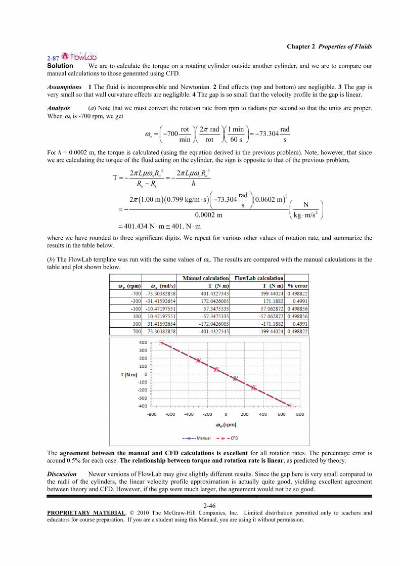
2-84 Solution We are to calculate the torque on a rotating cylinder inside another cylinder, and we are to compare our manual calculations to those generated using CFD. Assumptions 1 The fluid is incompressible and Newtonian. 2 End effects (top and bottom) are negligible. 3 The gap is very small so that wall curvature effects are negligible. 4 The gap is so small that the velocity profile in the gap is linear. Analysis (a) Note that we must convert the rotation rate from rpm to radians per second so that the units are proper. When ωi is -700 rpm, we get
rot 2 rad 1 min rad700 73.304min rot 60 s si
πω ⎛ ⎞⎛ ⎞⎛ ⎞= − = −⎜ ⎟⎜ ⎟⎜ ⎟⎝ ⎠⎝ ⎠⎝ ⎠
For h = 0.0002 m, the torque is calculated (using the equation derived in the previous problem). Note, however, that since we are calculating the torque of the fluid acting on the cylinder, the sign is opposite to that of the previous problem,
( )( ) ( )
3 3
3
2
2 2T
rad2 1.00 m 0.799 kg/m s 73.304 0.0600 mNs
0.0002 m kg m/s 397.445 N m 397. N m
i i i i
o i
L R L RR R h
π μω π μω
π
= − = −−
⎛ ⎞⋅ −⎜ ⎟ ⎛ ⎞⎝ ⎠= − ⎜ ⎟⋅⎝ ⎠= ⋅ ≅ ⋅
where we have rounded to three significant digits. We repeat for various other values of rotation rate, and summarize the results in the table below. (b) The FlowLab template was run with the same values of ωi. The results are compared with the manual calculations in the table and plot shown below.
The agreement between the manual and CFD calculations is excellent for all rotation rates. The percentage error is around 0.5% for each case. The relationship between torque and rotation rate is linear, as predicted by theory. Discussion Newer versions of FlowLab may give slightly different results. Since the gap here is very small compared to the radii of the cylinders, the linear velocity profile approximation is actually quite good, yielding excellent agreement between theory and CFD. However, if the gap were much larger, the agreement would not be so good.
2-85 Solution We are to calculate the torque on a rotating cylinder inside another cylinder, and we are to compare our manual calculations to those generated using CFD. Assumptions 1 The fluid is incompressible and Newtonian. 2 End effects (top and bottom) are negligible. 3 The gap is very small so that wall curvature effects are negligible. 4 The gap is so small that the velocity profile in the gap is linear. Analysis (a) First we convert the rotation rate from rpm to radians per second so that the units are proper,
rot 2 rad 1 min rad300 31.416min rot 60 s si
πω ⎛ ⎞⎛ ⎞⎛ ⎞= =⎜ ⎟⎜ ⎟⎜ ⎟⎝ ⎠⎝ ⎠⎝ ⎠
When h = 0.0002 m, the torque is calculated (using the equation derived in the previous problem). Note, however, that since we are calculating the torque of the fluid acting on the cylinder, the sign is opposite to that of the previous problem,
( )( ) ( )
3 3
3
2
2 2T
rad2 1.00 m 0.799 kg/m s 31.416 0.0600 mNs
0.0002 m kg m/s 170.336 N m 170. N m
i i i i
o i
L R L RR R h
π μω π μω
π
= − = −−
⎛ ⎞⋅ ⎜ ⎟ ⎛ ⎞⎝ ⎠= − ⎜ ⎟⋅⎝ ⎠= − ⋅ ≅ − ⋅
where we have rounded to three significant digits. We repeat for various other values of gap distance h, and summarize the results in the table below. (b) The FlowLab template was run with the same values of h. The results are compared with the manual calculations in the table and plot shown below. Note: We use absolute value of torque for comparison without worrying about the sign.
The agreement between the manual and CFD calculations is excellent for very small gaps (the percentage error is less than half a percent for the smallest gap). However, as the gap thickness increases, the agreement gets worse. By the time the gap is 0.04 m, the agreement is worse than 50%. Why such disagreement? Remember that we are assuming that the gap is very small and are approximating the velocity profile in the gap as linear. Apparently, the linear approximation breaks down as the gap gets larger. Discussion Newer versions of FlowLab may give slightly different results. We used a log scale for torque so that the differences between manual calculations and CFD could be more clearly seen.
2-86 Solution We are to determine the torque required to rotate the outer cylinder of two concentric cylinders, with the outer cylinder rotating and the inner cylinder stationary. Assumptions 1 The fluid is incompressible and Newtonian. 2 End effects (top and bottom) are negligible. 3 The gap is very small so that wall curvature effects are negligible. 4 The gap is so small that the velocity profile in the gap is linear. Analysis We assume a linear velocity profile between the two walls – the outer wall is moving at speed V = ωoRo and the inner wall is stationary. The thickness of the gap is h, and we let y be the distance from the outer wall into the fluid (towards the inner wall) as sketched. Thus,
and h y du Vu Vh dy h
τ μ μ−= = = −
where
- and o i o oh R R V Rω= =
Since shear stress τ has dimensions of force/area, the clockwise (mathematically negative) tangential force acting along the surface of the outer cylinder by the fluid is
2 2o oo o
o i
RVF A R L R Lh R R
μωτ μ π π= − = − = −−
But the torque is the tangential force times the moment arm Ro. Also, we are asked for the torque required to turn the inner cylinder. This applied torque is counterclockwise (mathematically positive). Thus,
3 32 2T o o o o
oo i
L R L RFRR R h
π μω π μω= − = =−
Discussion The above is only an approximation because we assumed a linear velocity profile. As long as the gap is very small, and therefore the wall curvature effects are negligible, this approximation should be very good. It is possible to solve for the exact velocity profile for this problem, and therefore the torque can be found analytically, but this has to wait until the differential analysis chapter.
2-87 Solution We are to calculate the torque on a rotating cylinder outside another cylinder, and we are to compare our manual calculations to those generated using CFD. Assumptions 1 The fluid is incompressible and Newtonian. 2 End effects (top and bottom) are negligible. 3 The gap is very small so that wall curvature effects are negligible. 4 The gap is so small that the velocity profile in the gap is linear. Analysis (a) Note that we must convert the rotation rate from rpm to radians per second so that the units are proper. When ωo is -700 rpm, we get
rot 2 rad 1 min rad700 73.304min rot 60 s so
πω ⎛ ⎞⎛ ⎞⎛ ⎞= − = −⎜ ⎟⎜ ⎟⎜ ⎟⎝ ⎠⎝ ⎠⎝ ⎠
For h = 0.0002 m, the torque is calculated (using the equation derived in the previous problem). Note, however, that since we are calculating the torque of the fluid acting on the cylinder, the sign is opposite to that of the previous problem,
( )( ) ( )
3 3
3
2
2 2T
rad2 1.00 m 0.799 kg/m s 73.304 0.0602 mNs
0.0002 m kg m/s 401.434 N m 401. N m
o o o o
o i
L R L RR R h
π μω π μω
π
= − = −−
⎛ ⎞⋅ −⎜ ⎟ ⎛ ⎞⎝ ⎠= − ⎜ ⎟⋅⎝ ⎠= ⋅ ≅ ⋅
where we have rounded to three significant digits. We repeat for various other values of rotation rate, and summarize the results in the table below. (b) The FlowLab template was run with the same values of ωo. The results are compared with the manual calculations in the table and plot shown below.
The agreement between the manual and CFD calculations is excellent for all rotation rates. The percentage error is around 0.5% for each case. The relationship between torque and rotation rate is linear, as predicted by theory. Discussion Newer versions of FlowLab may give slightly different results. Since the gap here is very small compared to the radii of the cylinders, the linear velocity profile approximation is actually quite good, yielding excellent agreement between theory and CFD. However, if the gap were much larger, the agreement would not be so good.
Surface Tension and Capillary Effect 2-88C Solution We are to define and discuss surface tension. Analysis The magnitude of the pulling force at the surface of a liquid per unit length is called surface tension σs. It is caused by the attractive forces between the molecules. The surface tension is also surface energy (per unit area) since it represents the stretching work that needs to be done to increase the surface area of the liquid by a unit amount. Discussion Surface tension is the cause of some very interesting phenomena such as capillary rise and insects that can walk on water.
2-89C Solution We are to analyze the pressure difference between inside and outside of a soap bubble. Analysis The pressure inside a soap bubble is greater than the pressure outside, as evidenced by the stretch of the soap film. Discussion You can make an analogy between the soap film and the skin of a balloon.
2-90C Solution We are to define and discuss the capillary effect. Analysis The capillary effect is the rise or fall of a liquid in a small-diameter tube inserted into the liquid. It is caused by the net effect of the cohesive forces (the forces between like molecules, like water) and adhesive forces (the forces between unlike molecules, like water and glass). The capillary effect is proportional to the cosine of the contact angle, which is the angle that the tangent to the liquid surface makes with the solid surface at the point of contact. Discussion The contact angle determines whether the meniscus at the top of the column is concave or convex.
2-91C Solution We are to determine whether the level of liquid in a tube will rise or fall due to the capillary effect. Analysis The liquid level in the tube will drop since the contact angle is greater than 90°, and cos(110°) < 0. Discussion This liquid must be a non-wetting liquid when in contact with the tube material. Mercury is an example of a non-wetting liquid with a contact angle (with glass) that is greater than 90o.
2-92C Solution We are to compare the capillary rise in small and large diameter tubes. Analysis The capillary rise is inversely proportional to the diameter of the tube, and thus capillary rise is greater in the smaller-diameter tube. Discussion Note however, that if the tube diameter is large enough, there is no capillary rise (or fall) at all. Rather, the upward (or downward) rise of the liquid occurs only near the tube walls; the elevation of the middle portion of the liquid in the tube does not change for large diameter tubes.
2-93 Solution An air bubble in a liquid is considered. The pressure difference between the inside and outside the bubble is to be determined. Properties The surface tension σs is given for two cases to be 0.08 and 0.12 N/m. Analysis Considering that an air bubble in a liquid has only one interface, he pressure difference between the inside and the outside of the bubble is determined from
RPPP s
iσ2
0bubble =−=Δ
Substituting, the pressure difference is determined to be:
(a) σs = 0.08 N/m: kPa 1.60===Δ 2bubble N/m 1600
m 0.0002/2N/m) 2(0.08P
(b) σs = 0.12 N/m: kPa 2.40===Δ 2bubble N/m 2400
m 0.0002/2N/m) 2(0.12
P
Discussion Note that a small gas bubble in a liquid is highly pressurized. The smaller the bubble diameter, the larger the pressure inside the bubble.
2-94 Solution A slender glass tube is inserted into kerosene. The capillary rise of kerosene in the tube is to be determined. Assumptions 1 There are no impurities in the kerosene, and no contamination on the surfaces of the glass tube. 2 The kerosene is open to the atmospheric air. Properties The surface tension of kerosene-glass at 20°C is σs = 0.028 N/m. The density of kerosene at 20°C is ρ = 820 kg/m3. The contact angle of kerosene with the glass surface is given to be 26°. Analysis Substituting the numerical values, the capillary rise is determined to be
mm 16≅=⎟⎟⎠
⎞⎜⎜⎝
⎛ ⋅×°
==−
m 0.0156N 1m/skg 1
m) 104.0)(m/s 81.9)(kg/m 820()26cosN/m)( 028.0(2cos2 2
323gRh s
ρφσ
Discussion The capillary rise in this case more than half of an inch, and thus it is clearly noticeable.
2-95 Solution A glass tube is inserted into a liquid, and the capillary rise is measured. The surface tension of the liquid is to be determined. Assumptions 1 There are no impurities in the liquid, and no contamination on the surfaces of the glass tube. 2 The liquid is open to the atmospheric air. Properties The density of the liquid is given to be 960 kg/m3. The contact angle is given to be 15°. Analysis Substituting the numerical values, the surface tension is determined from the capillary rise relation to be
N/m 0.0146=⎟⎟⎠
⎞⎜⎜⎝
⎛
⋅°==
2
23
m/skg 1 N 1
)15cos2(m) m)(0.005 2/0012.0)(m/s 81.9()kg/m 960(
cos2 φρσ gRh
s
Discussion Since surface tension depends on temperature, the value determined is valid at the liquid’s temperature.
2-96 [Also solved by EES on enclosed CD] Solution The diameter of a soap bubble is given. The gage pressure inside the bubble is to be determined. Assumptions The soap bubble is in atmospheric air. Properties The surface tension of soap water at 20°C is σs = 0.025 N/m. Analysis The pressure difference between the inside and the outside of a bubble is given by
RPPP s
iσ4
0bubble =−=Δ
In the open atmosphere P0 = Patm, and thus bubblePΔ is equivalent to the gage pressure. Substituting,
Discussion Note that the gage pressure in a soap bubble is inversely proportional to the radius (or diameter). Therefore, the excess pressure is larger in smaller bubbles.
2-97 Solution Nutrients dissolved in water are carried to upper parts of plants. The height to which the water solution rises in a tree as a result of the capillary effect is to be determined. Assumptions 1 The solution can be treated as water with a contact angle of 15°. 2 The diameter of the tube is constant. 3 The temperature of the water solution is 20°C. Properties The surface tension of water at 20°C is σs = 0.073 N/m. The density of water solution can be taken to be 1000 kg/m3. The contact angle is given to be 15°. Analysis Substituting the numerical values, the capillary rise is determined to be
m 14.4=⎟⎟⎠
⎞⎜⎜⎝
⎛ ⋅×°
==− N 1
m/skg 1m) 101)(m/s 81.9)(kg/m 1000(
)15cosN/m)( 073.0(2cos2 2
623gRh s
ρφσ
Discussion Other effects such as the chemical potential difference also cause the fluid to rise in trees.
2-98 Solution The force acting on the movable wire of a liquid film suspended on a U-shaped wire frame is measured. The surface tension of the liquid in the air is to be determined. Assumptions 1 There are no impurities in the liquid, and no contamination on the surfaces of the wire frame. 2 The liquid is open to the atmospheric air. Analysis Substituting the numerical values, the surface tension is determined from the surface tension force relation to be
N/m 0.15===)m 2(0.08
N 024.02bF
sσ
Discussion The surface tension depends on temperature. Therefore, the value determined is valid at the temperature of the liquid.
2-99 Solution A steel ball floats on water due to the surface tension effect. The maximum diameter of the ball is to be determined, and the calculations are to be repeated for aluminum. Assumptions 1 The water is pure, and its temperature is constant. 2 The ball is dropped on water slowly so that the inertial effects are negligible. 3 The contact angle is taken to be 0° for maximum diameter. Properties The surface tension of water at 20°C is σs = 0.073 N/m. The contact angle is taken to be 0°. The densities of steel and aluminum are given to be ρsteel = 7800 kg/m3 and ρAl = 2700 kg/m3. Analysis The surface tension force and the weight of the ball can be expressed as
ss DF σπ= and 6/3DggmgW πρρ === V
When the ball floats, the net force acting on the ball in the vertical direction is zero. Therefore, setting WFs = and solving
for diameter D gives g
D s
ρσ6
= . Substititing the known quantities, the maximum diameters for the steel and aluminum
balls become
mm 2.4=×=⎟⎟⎠
⎞⎜⎜⎝
⎛ ⋅== − m 104.2
N 1m/skg 1
)m/s )(9.81kg/m (7800 N/m) 073.0(66 3
2
23gD s
steel ρσ
mm 4.1=×=⎟⎟⎠
⎞⎜⎜⎝
⎛ ⋅== − m 101.4
N 1m/skg 1
)m/s )(9.81kg/m (2700 N/m) 073.0(66 3
2
23gD s
Al ρσ
Discussion Note that the ball diameter is inversely proportional to the square root of density, and thus for a given material, the smaller balls are more likely to float.
2-100 Solution A soap bubble is enlarged by blowing air into it. The required work input is to be determined. Properties The surface tension of solution is given to be σs = 0.039 N/m. Analysis The work associated with the stretching of a film is the surface tension work, and is expressed in differential form as ss dAW σδ =s . Noting that surface tension is constant, the surface tension work is simply surface tension multiplied by the change in surface area,
)(2)( 21
2212 DDAAW sss −=−= πσσ
The factor 2 is due to having two surfaces in contact with air. Substituting, the required work input is determined to be
( ) kJ 102.02 7-×=⎟⎠⎞
⎜⎝⎛
⋅−=
mN 1000kJ 1m) 080.0(m) 085.0()N/m 039.0(2 22πsW
Discussion Note that when a bubble explodes, an equivalent amount of energy is released to the environment.
Review Problems 2-101 Solution The cylinder conditions before the heat addition process is specified. The pressure after the heat addition process is to be determined. Assumptions 1 The contents of cylinder are approximated by the air properties. 2 Air is an ideal gas. Analysis The final pressure may be determined from the ideal gas relation
22 1
1
1300 273.15 K (1800 kPa) 3915.7450 273.15 K
TP PT
+⎛ ⎞= = = ≅⎜ ⎟+⎝ ⎠3920 kPa
Discussion Note that some forms of the ideal gas equation are more convenient to use than the other forms.
2-102 Solution A rigid tank contains an ideal gas at a specified state. The final temperature when half the mass is withdrawn and final pressure when no mass is withdrawn are to be determined. Analysis (a) The first case is a constant volume process. When half of the gas is withdrawn from the tank, the final temperature may be determined from the ideal gas relation as
( ) K 400=⎟⎠⎞
⎜⎝⎛== K) 600(
kPa 300kPa 10021
1
2
2
12 T
PP
mm
T
(b) The second case is a constant volume and constant mass process. The ideal gas relation for this case yields
kPa 200=⎟⎠⎞
⎜⎝⎛== kPa) 300(
K 600K 400
11
22 P
TT
P
Discussion Note that some forms of the ideal gas equation are more convenient to use than the other forms.
2-103 Solution The pressure in an automobile tire increases during a trip while its volume remains constant. The percent increase in the absolute temperature of the air in the tire is to be determined. Assumptions 1 The volume of the tire remains constant. 2 Air is an ideal gas. Analysis Noting that air is an ideal gas and the volume is constant, the ratio of absolute temperatures after and before the trip are
1.069= kPa290 kPa310=
1
2
1
2
2
22
1
11
PP
TT
TP
TP
=→=VV
Therefore, the absolute temperature of air in the tire will increase by 6.9% during this trip. Discussion This may not seem like a large temperature increase, but if the tire is originally at 20oC (293.15 K), the temperature increases to 1.069(293.15 K) = 313.38 K or about 40.2oC.
2-104 Solution A large tank contains nitrogen at a specified temperature and pressure. Now some nitrogen is allowed to escape, and the temperature and pressure of nitrogen drop to new values. The amount of nitrogen that has escaped is to be determined. Assumptions The tank is insulated so that no heat is transferred. Analysis Treating N2 as an ideal gas, the initial and the final masses in the tank are determined to be
kg 00.69K) K)(293/kgmkPa (0.2968
)m kPa)(10 (600
kg 45.90K) K)(298/kgmkPa (0.2968
)m kPa)(10 (800
3
3
2
22
3
3
1
11
=⋅⋅
==
=⋅⋅
==
RTP
m
RTP
m
V
V
Thus the amount of N2 that escaped is kg 21.5=−=−=Δ 00.6945.9021 mmm Discussion Gas expansion generally causes the temperature to drop. This principle is used in some types of refrigeration.
2-105 Solution Suspended solid particles in water are considered. A relation is to be developed for the specific gravity of the suspension in terms of the mass fraction , masssC and volume fraction , volsC of the particles. Assumptions 1 The solid particles are distributed uniformly in water so that the solution is homogeneous. 2 The effect of dissimilar molecules on each other is negligible. Analysis Consider solid particles of mass ms and volume Vs dissolved in a fluid of mass mf and volume Vm. The total volume of the suspension (or mixture) is fsm VVV +=
Dividing by Vm and using the definition msC VV / vols, = give
m
fvolsC
V
V+= ,1 → vols
m
f C ,1−=V
V (1)
The total mass of the suspension (or mixture) is fsm mmm +=
Dividing by mm and using the definition ms mmC /mass s, = give
mm
ffmasss
m
fmasss C
mm
CV
V
ρρ
+=+= ,,1 → f
mmasss
m
f CV
V)1( ,−=
ρρ
(2)
Combining equations 1 and 2 gives
vols
masss
m
f
CC
,
,
11
−−
=ρρ
When the fluid is water, the ratio mf ρρ / is the inverse of the definition of specific gravity. Therefore, the desired relation for the specific gravity of the mixture is
1
SG1
s ,volmm
f s ,mass
CC
ρρ
−= =
−
which is the desired result.
Discussion As a quick check, if there were no particles at all, SGm = 0, as expected.
2-106 Solution The specific gravities of solid particles and carrier fluids of a slurry are given. The relation for the specific gravity of the slurry is to be obtained in terms of the mass fraction , masssC and the specific gravity SGs of solid particles. Assumptions 1 The solid particles are distributed uniformly in water so that the solution is homogeneous. 2 The effect of dissimilar molecules on each other is negligible. Analysis Consider solid particles of mass ms and volume Vs dissolved in a fluid of mass mf and volume Vm. The total volume of the suspension (or mixture) is fsm VVV += . Dividing by Vm gives
m
f
m
s
V
V
V
V+=1 → mass
SG1 1 1 1
SGf s s s s m m
s ,m m m m m s s
m / mC
m / mρ ρρ ρ
= − = − = − = −V VV V
(1)
since ratio of densities is equal two the ratio of specific gravities, and mass s,/ Cmm ms = . The total mass of the suspension (or mixture) is fsm mmm += . Dividing by mm and using the definition ms mmC /mass s, = give
mass mass1 f f fs , s ,
m m m
mC C
mρρ
= + = +VV
→ mmasss
f
f
m
C V
V
)1( ,−=
ρρ
(2)
Taking the fluid to be water so that SGm f m/ρ ρ = and combining equations 1 and 2 give
mass
mass
1 SG SGSG
1s , m s
ms ,
C /C
−=
−
Solving for SGm and rearranging gives
s, mass
1SG1 1 SG 1m
sC ( )=
+ −
which is the desired result. Discussion As a quick check, if there were no particles at all, SGm = 0, as expected.
2-107 Solution Air in a partially filled closed water tank is evacuated. The absolute pressure in the evacuated space is to be determined. Properties The saturation pressure of water at 80°C is 47.42 kPa. Analysis When air is completely evacuated, the vacated space is filled with water vapor, and the tank contains a saturated water-vapor mixture at the given pressure. Since we have a two-phase mixture of a pure substance at a specified temperature, the vapor pressure must be the saturation pressure at this temperature. That is,
kPa 47.4≅== ° kPa 42.47Csat@80PPv Discussion If there is any air left in the container, the vapor pressure will be less. In that case the sum of the component pressures of vapor and air would equal 19.94 kPa.
Solution The variation of the dynamic viscosity of water with absolute temperature is given. Using tabular data, a relation is to be obtained for viscosity as a 4th-order polynomial. The result is to be compared to Andrade’s equation in the form of TBeD /⋅=μ .
Properties The viscosity data are given in tabular form as
T (K) μ (Pa⋅s) 273.15 1.787×10⁻³
278.15 1.519×10⁻³
283.15 1.307×10⁻³
293.15 1.002×10⁻³
303.15 7.975×10⁻⁴
313.15 6.529×10⁻⁴
333.15 4.665×10⁻⁴
353.15 3.547×10⁻⁴
373.15 2.828×10⁻⁴
Analysis Using EES, (1) Define a trivial function “a=mu+T” in the equation window, (2) select new parametric table from Tables, and type the data in a two-column table, (3) select Plot and plot the data, and (4) select plot and click on “curve fit” to get curve fit window. Then specify polynomial and enter/edit equation. The equations and plot are shown here. μ = 0.489291758 - 0.00568904387T + 0.0000249152104T2 - 4.86155745×10⁻⁸T3 + 3.56198079×10⁻¹¹T4 μ = 0.000001475*EXP(1926.5/T) [used initial guess of a0=1.8×10⁻⁶ and a1=1800 in mu=a0*exp(a1/T)] At T = 323.15 K, the polynomial and exponential curve fits give Polynomial: μ(323.15 K) = 0.0005529 Pa⋅s (1.1% error, relative to 0.0005468 Pa⋅s) Exponential: μ(323.15 K) = 0.0005726 Pa⋅s (4.7% error, relative to 0.0005468 Pa⋅s) Discussion This problem can also be solved using an Excel worksheet, with the following results: Polynomial: A = 0.4893, B = -0.005689, C = 0.00002492, D = -0.000000048612, and E = 0.00000000003562
Andrade’s equation: 1864 061 807952 6 . T. E * eμ = −
2-109 Solution The velocity profile for laminar one-dimensional flow between two parallel plates is given. A relation for friction drag force exerted on the plates per unit area of the plates is to be obtained. Assumptions 1 The flow between the plates is one-dimensional. 2 The fluid is Newtonian. Analysis The velocity profile is given by ( )[ ]2
max4)( hyhyuyu −= where h is the distance between the two plates, y is the vertical distance from the bottom plate, and umax is the maximum flow velocity that occurs at midplane. The shear stress at the bottom surface can be expressed as
hu
hy
hu
hy
hy
dydu
dydu
yyyw
max
02max
02
2
max0
42144μ
μμμτ =⎟⎠⎞
⎜⎝⎛ −=⎟⎟
⎠
⎞⎜⎜⎝
⎛−==
===
Because of symmetry, the wall shear stress is identical at both bottom and top plates. Then the friction drag force exerted by the fluid on the inner surface of the plates becomes
platemax8
2 Ahu
AF platewDμ
τ ==
Therefore, the friction drag per unit plate area is
hu
AFDmax
plate8
/μ
=
Discussion Note that the friction drag force acting on the plates is inversely proportional to the distance between plates
2-110 Solution The laminar flow of a Bingham plastic fluid in a horizontal pipe of radius R is considered. The shear stress at the pipe wall and the friction drag force acting on a pipe section of length L are to be determined. Assumptions 1 The fluid is a Bingham plastic with )( drduy μττ += where
τy is the yield stress. 2 The flow through the pipe is one-dimensional.
Analysis The velocity profile is given by )()(4
)( 22 RrRrL
Pru y −+−Δ=μ
τμ
where ΔP/L is the pressure drop along
the pipe per unit length, μ is the dynamic viscosity, r is the radial distance from the centerline. Its gradient at the pipe wall (r = R) is
⎟⎠⎞
⎜⎝⎛ +Δ=⎟⎟
⎠
⎞⎜⎜⎝
⎛+Δ=⎟⎟
⎠
⎞⎜⎜⎝
⎛−+−Δ=
===y
Rr
y
Rr
y
RrR
LP
LPrRrRr
LP
drd
drdu τ
μμτ
μμτ
μ 21
42)()(
422
Substituing into )( drduy μττ += , the wall shear stress at the pipe surface becomes
RLPR
LP
drdu
yyyRr
yw 22
2Δ+=+Δ+=+=
=τττμττ
Then the friction drag force exerted by the fluid on the inner surface of the pipe becomes
PRRLRLPRLRLR
LPAF yyyswD Δ+=⎟
⎠⎞
⎜⎝⎛ Δ+=⎟
⎠⎞
⎜⎝⎛ Δ+== 24
222)2(
22 πτπτππττ
Discussion Note that the total friction drag is proportional to yield shear stress and the pressure drop.
2-111 Solution A circular disk immersed in oil is used as a damper, as shown in the figure. It is to be shown that the damping torque is ωC=dampingT where ( ) 4115.0 RbaC += πμ .
Assumptions 1 The thickness of the oil layer on each side remains constant. 2 The velocity profiles are linear on both sides of the disk. 3 The tip effects are negligible. 4 The effect of the shaft is negligible. Analysis The velocity gradient anywhere in the oil of film thickness a is V/a where V = ωr is the tangential velocity. Then the wall shear stress anywhere on the upper surface of the disk at a distance r from the axis of rotation can be expressed as
wdu V rdy a a
ωτ μ μ μ= = =
Then the shear force acting on a differential area dA on the surface and the torque it generates can be expressed as
dAardAdF w
ωμτ ==
dAarrdFd
2T ωμ==
Noting that rdrdA π2= and integrating, the torque on the top surface is determined to be
aRr
adrr
adrrr
adAr
a
R
r
R
r
R
rA 2422)2(T
4
0
43
0
2
0
2top
πμωπμωπμωπμωμω ======
== ∫∫∫
The torque on the bottom surface is obtained by replaying a by b,
bR
2T
4
bottomπμω=
The total torque acting on the disk is the sum of the torques acting on the top and bottom surfaces,
⎟⎠⎞
⎜⎝⎛ +=+=
baR 11
2TTT
4
topbottom totaldamping,πμω
or,
ωC= totaldamping,T where ⎟⎠⎞
⎜⎝⎛ +=
baRC 112
4πμ
This completes the proof. Discussion Note that the damping torque (and thus damping power) is inversely proportional to the thickness of oil films on either side, and it is proportional to the 4th power of the radius of the damper disk.
2-112 Solution A glass tube is inserted into mercury. The capillary drop of mercury in the tube is to be determined. Assumptions 1 There are no impurities in mercury, and no contamination on the surfaces of the glass tube. 2 The mercury is open to the atmospheric air. Properties The surface tension of mercury-glass in atmospheric air at 20°C is σs = 0.440 N/m. The density of mercury is ρ = 13,550 kg/m3 at 20°C. The contact angle is given to be 140°. Analysis Substituting the numerical values, the capillary drop is determined to be
mm 2.25−=−=
⎟⎟⎠
⎞⎜⎜⎝
⎛ ⋅°==
m 002254.0
N 1m/skg 1
m) 00225.0)(m/s 81.9)(kg/m 550,13()140cosN/m)( 440.0(2cos2 2
23gRh s
ρφσ
Discussion The negative sign indicates capillary drop instead of rise. The drop is very small in this case because of the large diameter of the tube.
2-113 Solution A relation is to be derived for the capillary rise of a liquid between two large parallel plates a distance t apart inserted into a liquid vertically. The contact angle is given to be φ. Assumptions There are no impurities in the liquid, and no contamination on the surfaces of the plates. Analysis The magnitude of the capillary rise between two large parallel plates can be determined from a force balance on the rectangular liquid column of height h and width w between the plates. The bottom of the liquid column is at the same level as the free surface of the liquid reservoir, and thus the pressure there must be atmospheric pressure. This will balance the atmospheric pressure acting from the top surface, and thus these two effects will cancel each other. The weight of the liquid column is
)( htwggmgW ××=== ρρ V Equating the vertical component of the surface tension force to the weight gives
φσρ cos2)( ssurface whtwgFW =××→= Canceling w and solving for h gives the capillary rise to be
Capillary rise: gt
h s
ρφσ cos2
=
Discussion The relation above is also valid for non-wetting liquids (such as mercury in glass), and gives a capillary drop instead of a capillary rise.
2-114 Solution A journal bearing is lubricated with oil whose viscosity is known. The torques needed to overcome the bearing friction during start-up and steady operation are to be determined. Assumptions 1 The gap is uniform, and is completely filled with oil. 2 The end effects on the sides of the bearing are negligible. 3 The fluid is Newtonian. Properties The viscosity of oil is given to be 0.1 kg/m⋅s at 20°C, and 0.008 kg/m⋅s at 80°C. Analysis The radius of the shaft is R = 0.04 m. Substituting the given values, the torque is determined to be At start up at 20°C:
mN 1.68 ⋅=⋅==m0008.0
m) 40.0)(s 60/800(m) 04.0(4)skg/m 1.0(4 -13232 ππμl
&LnRT
During steady operation at 80°C:
mN 0.135 ⋅=⋅==m0008.0
m) 40.0)(s 60/800(m) 04.0(4)skg/m 008.0(4 -13232 ππμl
&LnRT
Discussion Note that the torque needed to overcome friction reduces considerably due to the decrease in the viscosity of oil at higher temperature.
2-115 Solution A cylindrical shaft rotates inside an oil bearing at a specified speed. The power required to overcome friction is to be determined. Assumptions 1 The gap is uniform, and is completely filled with oil. 2 The end effects on the sides of the bearing are negligible. 3 The fluid is Newtonian. Properties The viscosity of oil is given to be 0.300 N⋅s/m2. Analysis (a) The radius of the shaft is R = 0.05 m, and thickness of the oil layer is l = (10.3 – 10)/2 = 0.15 cm. The power-torque relationship is
TT nW && πω 2== where, from Chap. 2, l
&LnR 324πμ=T
Substituting, the required power to overcome friction is determined to be
W186=⎟⎠⎞
⎜⎝⎛
⋅⋅==
m/sN 1W 1
m 0015.0m) 40.0()s 60/600(m) 05.0(6
)s/m3N.0(6 2-1332
233 ππμl
&& LnRW
(b) For the case of rpm1200=n& :
W744=⎟⎠⎞
⎜⎝⎛
⋅⋅==
m/sN 1W 1
m 0015.0m) 40.0()s 60/1200(m) 05.0(6
)s/m3N.0(6 2-1332
233 ππμl
&& LnRW
Discussion Note the power dissipated in journal bearing is proportional to the cube of the shaft radius and to the square of the shaft speed, and is inversely proportional to the oil layer thickness.
2-116 Solution A U-tube with a large diameter arm contains water. The difference between the water levels of the two arms is to be determined. Assumptions 1 Both arms of the U-tube are open to the atmosphere. 2 Water is at room temperature. 3 The contact angle of water is zero, φ = 0. Properties The surface tension and density of water at 20°C are σs = 0.073 N/m and ρ = 1000 kg/m3. Analysis Any difference in water levels between the two arms is due to surface tension effects and thus capillary rise. Noting that capillary rise in a tube is inversely proportional to tube diameter there will be no capillary rise in the arm with a large diameter. Then the water level difference between the two arms is simply the capillary rise in the smaller diameter arm,
2
3 2
2 cos 2(0.073 N/m)(cos0 ) 1 kg m/s 1000 mm(1000 kg/m )(9.81 m/s )(0.0025 m) 1 N 1 m
shgR
σ φρ
⎛ ⎞° ⋅ ⎛ ⎞= = =⎜ ⎟⎜ ⎟⎝ ⎠⎝ ⎠
5.95 mm
Discussion Note that this is a significant difference, and shows the importance of using a U-tube made of a uniform diameter tube.
2-117 Solution Air spaces in certain bricks form air columns of a specified diameter. The height that water can rise in those tubes is to be determined. Assumptions 1 The interconnected air pockets form a cylindrical air column. 2 The air columns are open to the atmospheric air. 3 The contact angle of water is zero, φ = 0. Properties The surface tension is given to be 0.085 N/m, and we take the water density to be 1000 kg/m3. Analysis Substituting the numerical values, the capillary rise is determined to be
m 8.66=⎟⎟⎠
⎞⎜⎜⎝
⎛ ⋅×°
== − N 1m/s kg1
m) 102)(m/s 81.9)( kg/m1000()0cosN/m)( 085.0(2cos2 2
623gRh s
ρφσ
Discussion The surface tension depends on temperature. Therefore, the value determined may change with temperature.
Design and Essay Problems 2-118, 2-119, 2-120 Solution Students’ essays and designs should be unique and will differ from each other.
2-121 Solution We are to determine the inlet water speed at which cavitation is likely to occur in the throat of a converging-diverging tube or duct, and repeat for a higher temperature. Assumptions 1 The fluid is incompressible and Newtonian. 2 Gravitational effects are negligible. 3 Irreversibilities are negligible. 4 The equations provided are valid for this flow. Properties For water at 20oC, ρ = 998.0 kg/m3 and Psat = 2.339 kPa. Analysis (a) Two equations are given for velocity, pressure, and cross-sectional area, namely,
1 1 2 2V A V A= and 2 2
1 21 22 2
V VP Pρ ρ+ = +
Solving the first equation for V2 gives
12 1
2
AV VA
= (1)
Substituting the above into the equation for pressure and solving for V1 yields, after some algebra,
( )1 2
1 2
1
2
2
1
P PV
AA
ρ
−=
⎛ ⎞⎛ ⎞⎜ ⎟−⎜ ⎟⎜ ⎟⎝ ⎠⎝ ⎠
But the pressure at which cavitation is likely to occur is the vapor (saturation) pressure of the water. We also know that throat diameter D2 is 1/20 times the inlet diameter D1, and since A = πD2/4, A1/A2 = (20)2 = 400. Thus,
( )
( )2 2
12
3
2 20.803 2.339 kPa 1000 N/m 1 kg m/s m0.015207kg kPa N s998.0 400 1m
V− ⎛ ⎞⎛ ⎞⋅= =⎜ ⎟⎜ ⎟
⎝ ⎠⎝ ⎠−
So, the minimum inlet velocity at which cavitation is likely to occur is 0.0152 m/s (to three significant digits). The velocity at the throat is much faster than this, of course. Using Eq. (1),
2 22
1 1 11 1 12
200.015207 6.0828 m/s1t
t t t
A D DV V V VA D D
ππ
⎛ ⎞ ⎛ ⎞= = = = =⎜ ⎟ ⎜ ⎟⎝ ⎠⎝ ⎠
(b) If the water is warmer (50oC), the density reduces to 988.1 kg/m3, and the vapor pressure increases to 12.35 kPa. At these conditions, V1 = 0.0103 m/s. As might be expected, at higher temperature, a lower inlet velocity is required to generate cavitation, since the water is warmer and already closer to its boiling point. Discussion Cavitation is usually undesirable since it leads to noise, and the collapse of the bubbles can be destructive. It is therefore often wise to design piping systems and turbomachinery to avoid cavitation.
2-122 Solution We are to use CFD to determine the inlet water speed at which cavitation is likely to occur in the throat of a converging-diverging tube or duct. Assumptions 1 The fluid is incompressible and Newtonian. 2 Gravitational effects are negligible. 3 Irreversibilities are accounted for in the CFD code. 4 The flow is laminar. Properties For water at 20oC, ρ = 998.0 kg/m3 and Psat = 2.339 kPa. The outlet absolute pressure is set to 11.372 kPa. Analysis We run FlowLab at various inlet velocities, monitoring the throat pressure. When the throat pressure falls below the vapor pressure (2.339 kPa), we predict that cavitation is likely to occur. Results: With Poutlet = 11.372 kPa and Vinlet = 0.01413 m/s, the inlet pressure is 20.80 kPa and the throat pressure is 2.339 kPa. Thus, the minimum inlet velocity at which cavitation is likely to occur is 0.0141 m/s (to three significant digits). The result from the previous problem was 0.0152 m/s. In that analysis, friction along the duct walls was neglected. In real life, friction is not negligible, and the equation used for pressure in the previous problem does not hold. The CFD inlet velocity is a little smaller than the analytical result, as expected, due to the increase in pressure drop caused by friction. Discussion CFD is useful in situations where an exact analytical analysis is not possible and/or the approximations or assumptions required to generate an analytical solution break down.
2-123 Solution We are to explain how objects like razor blades and paper clips can float on water, even though they are much denser than water. Analysis Just as some insects like water striders can be supported on water by surface tension, surface tension is the key to explaining this phenomenon. If we think of surface tension like a skin on top of the water, somewhat like a stretched piece of balloon, we can understand how something heavier than water pushes down on the surface, but the surface tension forces counteract the weight (to within limits) by providing an upward force. Since soap decreases surface tension, we expect that it would be harder to float objects like this on a soapy surface; with a high enough soap concentration, in fact, we would expect that the razor blade or paper clip could not float at all. Discussion If the razor blade or paper clip is fully submerged (breaking through the surface tension), it sinks.