48
» Save time & cost » Meets demanding machine requirements » Increases machine efficiency, performance & availability The 5-star servo drive SIGMA-5

» Save t i m e & cos t» M e e t s d e m a n d i n g m a c h i n e re q u i re m e n t s
» I n c r e a s e s m a c h i n e e f f i c i e n c y , p e r f o r m a n c e & a v a i l a b i l i t y
T h e 5 - s t a r s e r v o d r i v e
Sigma-5
Sigma-5: the 5-star servo drive…
It is a primary goal of OMRON YASKAWA to offer
customers products and solutions that meet
their needs. And the Sigma-5 servo drive offers
exactly that. Precise positioning at the highest
speed. Smooth and vibration-free operation.
And the easiest possible start up. For machine
builders this translates into better machine
performance to meet exacting machine
requirements. It also has a significant impact
on increasing machine availability while
reducing costs.
As Sigma-5 belongs to the product portfolio
of a global leader in automation, you will have total
world-wide service and support throughout the
product life cycle. Moreover, ongoing technical
developments by Omron will keep your machines
in front, giving you an edge, both now and
in the future.
…value delivered
• Meets the most demanding machine
requirements
• Helps to maximize machine performance
• Minimizes total cost of ownership
• Increases machine availability
…enhance machine efficiency while saving time and costs
The Sigma-5 servo drive excels in even the most
demanding axis-control operations and applications,
including those in the following industries and
applications:
• Electronics
• Semiconductors
• Packaging
• Printing
• Machine tools
• Injection moulding
• Metal forming
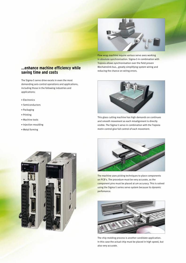
Flow wrap machine require various servo axes working
in absolute synchronisation. Sigma-5 in combination with
Trajexia allows synchronisation over the field proven
Mechatrolink bus., greatly simplifying system wiring and
reducing the chance on wiring errors.
This glass cutting machine has high demands on continues
and smooth movement as each misalignment is directly
visible. The Sigma-5 servo in combination with the Trajexia
motin control give full control of each movement.
The machine uses picking techniques to place components
on PCB‘s. The procedure must be very accurate, as the
component pins must be placed at um accuracy. This is solved
using the Sigma-5 series servo system because its dynamic
perfomance.
The chip molding process is another candidate application.
In this case the actual chip must be placed in high speed, but
also very accurate.
New compact size!
Five reasons to choose Sigma-5
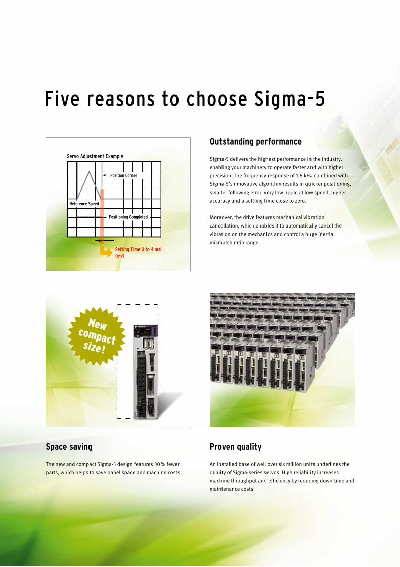
Outstanding performance
Sigma-5 delivers the highest performance in the industry,
enabling your machinery to operate faster and with higher
precision. The frequency response of 1.6 kHz combined with
Sigma-5’s innovative algorithm results in quicker positioning,
smaller following error, very low ripple at low speed, higher
accuracy and a settling time close to zero.
Moreover, the drive features mechanical vibration
cancellation, which enables it to automatically cancel the
vibration on the mechanics and control a huge inertia
mismatch ratio range.
Space saving
The new and compact Sigma-5 design features 30 % fewer
parts, which helps to save panel space and machine costs.
Proven quality
An installed base of well over six million units underlines the
quality of Sigma-series servos. High reliability increases
machine throughput and efficiency by reducing down-time and
maintenance costs.
Servo Adjustment Example
Position Corner
Setting Time 0 to 4 msl (x-v)
Reference Speed
Positioning Completed
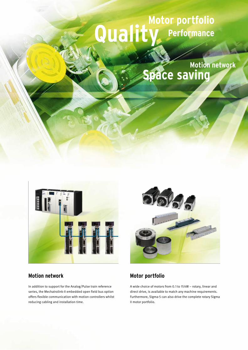
motion network
In addition to support for the Analog/Pulse train reference
series, the Mechatrolink-II embedded open field bus option
offers flexible communication with motion controllers whilst
reducing cabling and installation time.
motor portfolio
A wide choice of motors from 0.1 to 15 kW – rotary, linear and
direct drive, is available to match any machine requirements.
Furthermore, Sigma-5 can also drive the complete rotary Sigma
II motor portfolio.
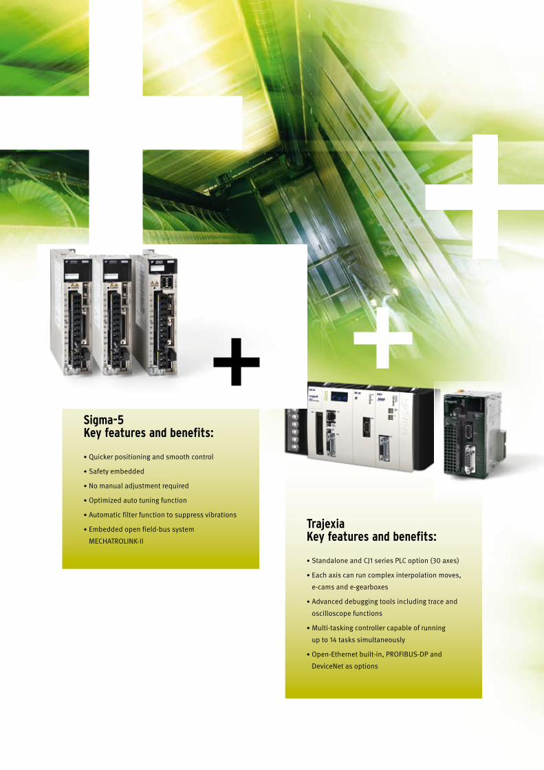
Sigma-5 Key features and benefits:
• Quicker positioning and smooth control
• Safety embedded
• No manual adjustment required
• Optimized auto tuning function
• Automatic filter function to suppress vibrations
• Embedded open field-bus system
MECHATROLINK-II
Trajexia Key features and benefits:
• Standalone and CJ1 series PLC option (30 axes)
• Each axis can run complex interpolation moves,
e-cams and e-gearboxes
• Advanced debugging tools including trace and
oscilloscope functions
• Multi-tasking controller capable of running
up to 14 tasks simultaneously
• Open-Ethernet built-in, PROFIBUS-DP and
DeviceNet as options
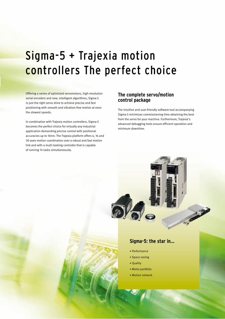
Offering a series of optimized servomotors, high-resolution
serial encoders and new, intelligent algorithms, Sigma-5
is just the right servo drive to achieve precise and fast
positioning with smooth and vibration-free motion at even
the slowest speeds.
In combination with Trajexia motion controllers, Sigma-5
becomes the perfect choice for virtually any industrial
application demanding precise control with positional
accuracies up to 10nm. The Trajexia platform offers 4, 16 and
30-axes motion coordination over a robust and fast motion
link and with a multi-tasking controller that is capable
of running 14 tasks simultaneously.
The complete servo/motion control package
The intuitive and user-friendly software tool accompanying
Sigma-5 minimizes commissioning time obtaining the best
from the servo for your machine. Furthermore, Trajexia’s
advanced debugging tools ensure efficient operation and
minimum downtime.
Sigma-5: the star in…
• Performance
• Space saving
• Quality
• Motor portfolio
• Motion network
Sigma-5 + Trajexia motion controllers The perfect choice
1Sigma-5 servo system
AC
Ser
vo s
yste
ms
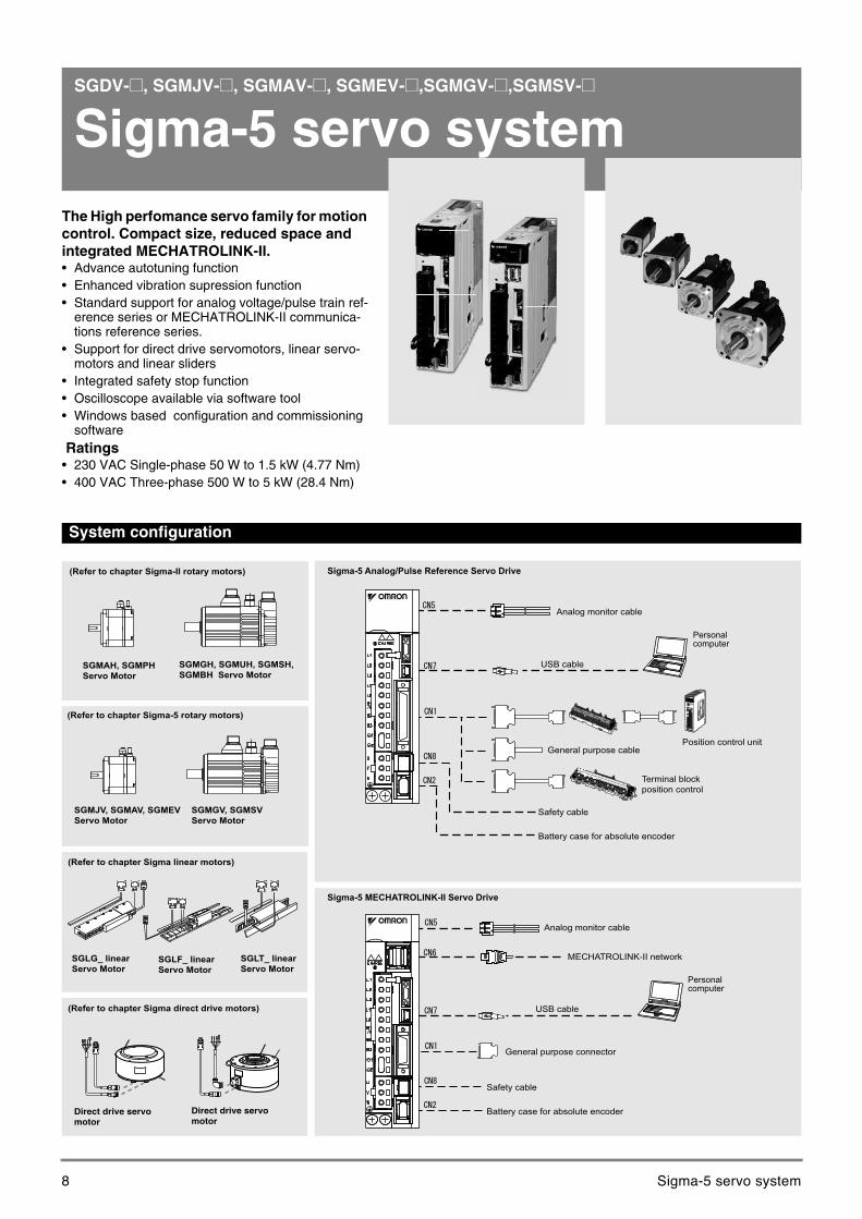
SGDV-@, SGMJV-@, SGMAV-@, SGMEV-@,SGMGV-@,SGMSV-@
Sigma-5 servo systemThe High perfomance servo family for motion control. Compact size, reduced space and integrated MECHATROLINK-II.• Advance autotuning function• Enhanced vibration supression function• Standard support for analog voltage/pulse train ref-
erence series or MECHATROLINK-II communica-tions reference series.
• Support for direct drive servomotors, linear servo-motors and linear sliders
• Integrated safety stop function• Oscilloscope available via software tool• Windows based configuration and commissioning
software Ratings• 230 VAC Single-phase 50 W to 1.5 kW (4.77 Nm)• 400 VAC Three-phase 500 W to 5 kW (28.4 Nm)
System configuration
SGMGH, SGMUH, SGMSH, SGMBH Servo Motor
(Refer to chapter Sigma linear motors)
SGMAH, SGMPHServo Motor
SGLT_ linearServo Motor
SGLG_ linearServo Motor
SGLF_ linear Servo Motor
(Refer to chapter Sigma-II rotary motors)
SGMGV, SGMSV Servo Motor
SGMJV, SGMAV, SGMEVServo Motor
(Refer to chapter Sigma-5 rotary motors)
Direct drive servo motor
Direct drive servo motor
(Refer to chapter Sigma direct drive motors)
Battery case for absolute encoder
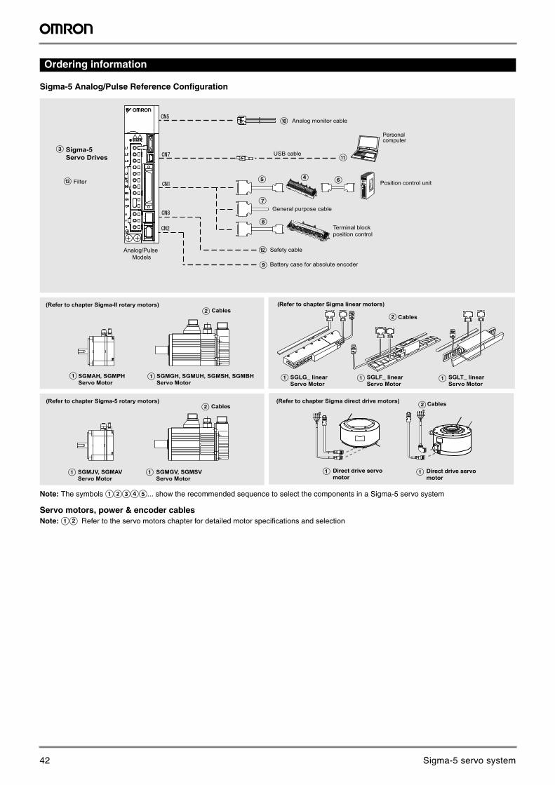
Analog monitor cable
USB cable
Safety cable
MECHATROLINK-II network
General purpose connector
Personalcomputer
Battery case for absolute encoder
Analog monitor cable
USB cable
Safety cable
Sigma-5 Analog/Pulse Reference Servo Drive
Position control unit
Terminal block position control
General purpose cable
Personalcomputer
Sigma-5 MECHATROLINK-II Servo Drive
8 Sigma-5 servo system
2 AC servo systems
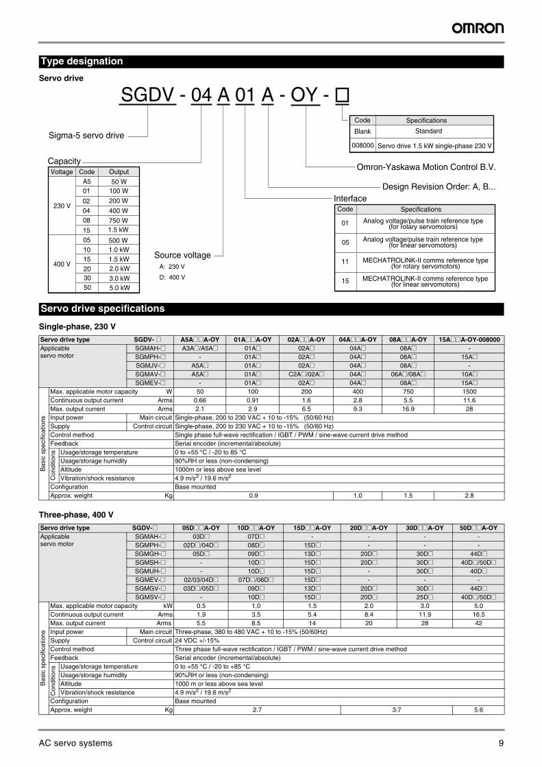
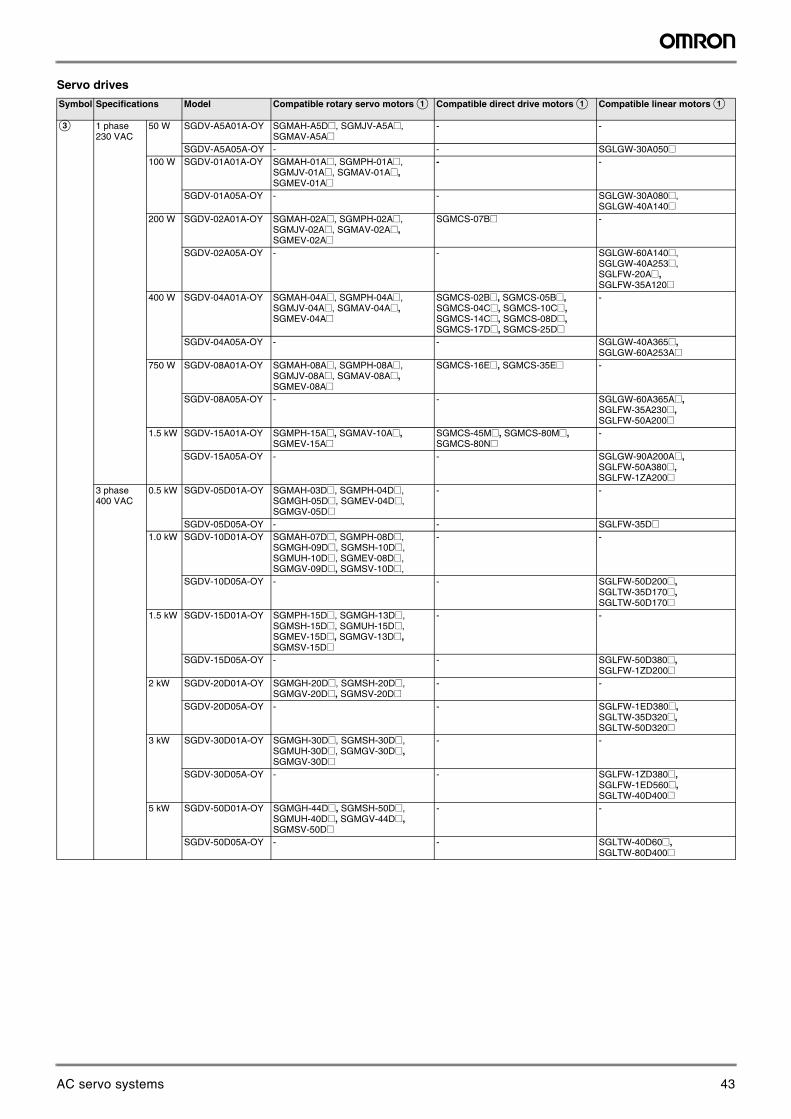
Servo drive
Single-phase, 230 V
Three-phase, 400 V
Type designation
Servo drive specifications
Servo drive type SGDV- @ A5A@@A-OY 01A@@A-OY 02A@@A-OY 04A@@A-OY 08A@@A-OY 15A@@A-OY-008000Applicable servo motor
SGMAH-@ A3A@/A5A@ 01A@ 02A@ 04A@ 08A@ -SGMPH-@ - 01A@ 02A@ 04A@ 08A@ 15A@SGMJV-@ A5A@ 01A@ 02A@ 04A@ 08A@ -SGMAV-@ A5A@ 01A@ C2A@/02A@ 04A@ 06A@/08A@ 10A@SGMEV-@ - 01A@ 02A@ 04A@ 08A@ 15A@
Bas
ic s
peci
ficat
ions
Max. applicable motor capacity W 50 100 200 400 750 1500Continuous output current Arms 0.66 0.91 1.6 2.8 5.5 11.6Max. output current Arms 2.1 2.9 6.5 9.3 16.9 28Input power Main circuit Single-phase, 200 to 230 VAC + 10 to -15% (50/60 Hz)Supply Control circuit Single-phase, 200 to 230 VAC + 10 to -15% (50/60 Hz)Control method Single phase full-wave rectification / IGBT / PWM / sine-wave current drive methodFeedback Serial encoder (incremental/absolute)
Con
ditio
ns Usage/storage temperature 0 to +55 °C / -20 to 85 °CUsage/storage humidity 90%RH or less (non-condensing)Altitude 1000m or less above sea levelVibration/shock resistance 4.9 m/s2 / 19.6 m/s2
Configuration Base mounted Approx. weight Kg 0.9 1.0 1.5 2.8
Servo drive type SGDV-@ 05D@@A-OY 10D@@A-OY 15D@@A-OY 20D@@A-OY 30D@@A-OY 50D@@A-OYApplicable servo motor
SGMAH-@ 03D@ 07D@ - - - -SGMPH-@ 02D@/04D@ 08D@ 15D@ - - -SGMGH-@ 05D@ 09D@ 13D@ 20D@ 30D@ 44D@SGMSH-@ - 10D@ 15D@ 20D@ 30D@ 40D@/50D@SGMUH-@ - 10D@ 15D@ - 30D@ 40D@SGMEV-@ 02/03/04D@ 07D@/08D@ 15D@ - - -SGMGV-@ 03D@/05D@ 09D@ 13D@ 20D@ 30D@ 44D@SGMSV-@ - 10D@ 15D@ 20D@ 25D@ 40D@/50D@
Bas
ic s
peci
ficat
ions
Max. applicable motor capacity kW 0.5 1.0 1.5 2.0 3.0 5.0Continuous output current Arms 1.9 3.5 5.4 8.4 11.9 16.5Max. output current Arms 5.5 8.5 14 20 28 42Input power Main circuit Three-phase, 380 to 480 VAC + 10 to -15% (50/60Hz) Supply Control circuit 24 VDC +/-15%Control method Three phase full-wave rectification / IGBT / PWM / sine-wave current drive methodFeedback Serial encoder (incremental/absolute)
Con
ditio
ns
Usage/storage temperature 0 to +55 °C / -20 to +85 °CUsage/storage humidity 90%RH or less (non-condensing)Altitude 1000 m or less above sea levelVibration/shock resistance 4.9 m/s2 / 19.6 m/s2
Configuration Base mountedApprox. weight Kg 2.7 3.7 5.6
Sigma-5 servo drive
Design Revision Order: A, B...
Source voltage A: 230 V
D: 400 V
Code
01
05
11
15
Specifications
Analog voltage/pulse train reference type(for rotary servomotors)
Analog voltage/pulse train reference type(for linear servomotors)
MECHATROLINK-II comms reference type(for rotary servomotors)
MECHATROLINK-II comms reference type(for linear servomotors)
Interface
Voltage Code
230 V
OutputCapacity
50 W
400 V
A50102040815051015203050
200 W100 W
400 W750 W1.5 kW
500 W1.0 kW1.5 kW
2.0 kW3.0 kW5.0 kW
Omron-Yaskawa Motion Control B.V.
Code
Blank
008000
Specifications
Standard
Servo drive 1.5 kW single-phase 230 V
9AC servo systems
Sigma-5 servo system 3
AC
Ser
vo s
yste
ms
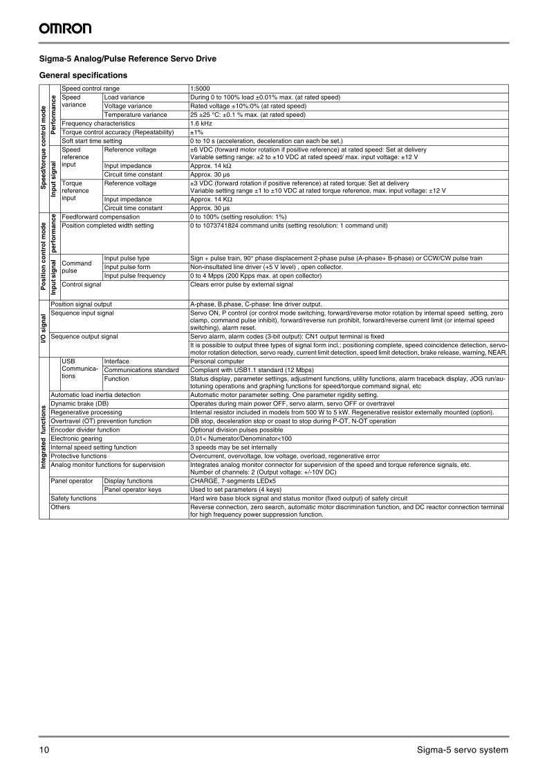
Sigma-5 Analog/Pulse Reference Servo Drive
General specifications
Sp
eed
/to
rqu
e co
ntr
ol m
od
e
Per
form
ance
Speed control range 1:5000Speedvariance
Load variance During 0 to 100% load ±0.01% max. (at rated speed)Voltage variance Rated voltage ±10%:0% (at rated speed)Temperature variance 25 ±25 °C: ±0.1 % max. (at rated speed)
Frequency characteristics 1.6 kHzTorque control accuracy (Repeatability) ±1%Soft start time setting 0 to 10 s (acceleration, deceleration can each be set.)
Inp
ut
sig
nal
Speed reference input
Reference voltage ±6 VDC (forward motor rotation if positive reference) at rated speed: Set at deliveryVariable setting range: ±2 to ±10 VDC at rated speed/ max. input voltage: ±12 V
Input impedance Approx. 14 kΩCircuit time constant Approx. 30 µs
Torque referenceinput
Reference voltage ±3 VDC (forward rotation if positive reference) at rated torque: Set at deliveryVariable setting range ±1 to ±10 VDC at rated torque reference, max. input voltage: ±12 V
Input impedance Approx. 14 KΩ Circuit time constant Approx. 30 µs
Po
siti
on
co
ntr
ol m
od
e
per
form
ance Feedforward compensation 0 to 100% (setting resolution: 1%)
Position completed width setting 0 to 1073741824 command units (setting resolution: 1 command unit)
Inp
ut s
ign
al
Command pulse
Input pulse type Sign + pulse train, 90° phase displacement 2-phase pulse (A-phase+ B-phase) or CCW/CW pulse trainInput pulse form Non-insultated line driver (+5 V level) , open collector.Input pulse frequency 0 to 4 Mpps (200 Kpps max. at open collector)
Control signal Clears error pulse by external signal
I/O s
ign
al
Position signal output A-phase, B.phase, C-phase: line driver output.Sequence input signal Servo ON, P control (or control mode switching, forward/reverse motor rotation by internal speed setting, zero
clamp, command pulse inhibit), forward/reverse run prohibit, forward/reverse current limit (or internal speed switching), alarm reset.
Sequence output signal Servo alarm, alarm codes (3-bit output): CN1 output terminal is fixedIt is possible to output three types of signal form incl.: positioning complete, speed coincidence detection, servo-motor rotation detection, servo ready, current limit detection, speed limit detection, brake release, warning, NEAR.
Inte
gra
ted
fu
nct
ion
s
USBCommunica-tions
Interface Personal computerCommunications standard Compliant with USB1.1 standard (12 Mbps)Function Status display, parameter settings, adjustment functions, utility functions, alarm traceback display, JOG run/au-
totuning operations and graphing functions for speed/torque command signal, etcAutomatic load inertia detection Automatic motor parameter setting. One parameter rigidity setting.Dynamic brake (DB) Operates during main power OFF, servo alarm, servo OFF or overtravelRegenerative processing Internal resistor included in models from 500 W to 5 kW. Regenerative resistor externally mounted (option).Overtravel (OT) prevention function DB stop, deceleration stop or coast to stop during P-OT, N-OT operationEncoder divider function Optional division pulses possibleElectronic gearing 0,01< Numerator/Denominator<100Internal speed setting function 3 speeds may be set internallyProtective functions Overcurrent, overvoltage, low voltage, overload, regenerative errorAnalog monitor functions for supervision Integrates analog monitor connector for supervision of the speed and torque reference signals, etc.
Number of channels: 2 (Output voltage: +/-10V DC)Panel operator Display functions CHARGE, 7-segments LEDx5
Panel operator keys Used to set parameters (4 keys)Safety functions Hard wire base block signal and status monitor (fixed output) of safety circuitOthers Reverse connection, zero search, automatic motor discrimination function, and DC reactor connection terminal
for high frequency power suppression function.
10 Sigma-5 servo system
4 AC servo systems
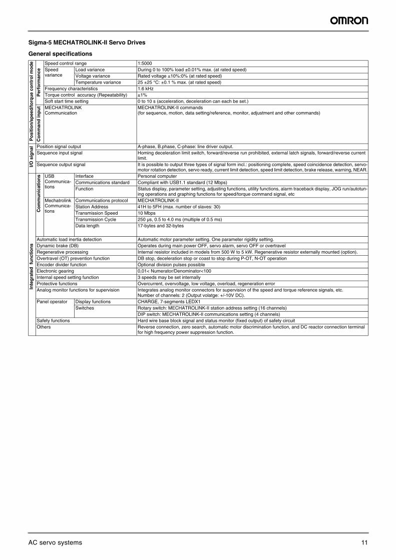
Sigma-5 MECHATROLINK-II Servo Drives
General specifications
Po
siti
on
/sp
eed
/to
rqu
e co
ntr
ol m
od
e
Per
form
ance
Speed control range 1:5000Speedvariance
Load variance During 0 to 100% load ±0.01% max. (at rated speed)Voltage variance Rated voltage ±10%:0% (at rated speed)Temperature variance 25 ±25 °C: ±0.1 % max. (at rated speed)
Frequency characteristics 1.6 kHzTorque control accuracy (Repeatability) ±1%Soft start time setting 0 to 10 s (acceleration, deceleration can each be set.)
Co
mm
and
inp
ut MECHATROLINK
CommunicationMECHATROLINK-II commands(for sequence, motion, data setting/reference, monitor, adjustment and other commands)
I/
O s
ign
al Position signal output A-phase, B.phase, C-phase: line driver output.Sequence input signal Homing deceleration limit switch, forward/reverse run prohibited, external latch signals, forward/reverse current
limit.Sequence output signal It is possible to output three types of signal form incl.: positioning complete, speed coincidence detection, servo-
motor rotation detection, servo ready, current limit detection, speed limit detection, brake release, warning, NEAR.
I
nte
gra
ted
fu
nct
ion
s
Co
mm
un
icat
ion
s USBCommunica-tions
Interface Personal computerCommunications standard Compliant with USB1.1 standard (12 Mbps)Function Status display, parameter setting, adjusting functions, utility functions, alarm traceback display, JOG run/autotun-
ing operations and graphing functions for speed/torque command signal, etcMechatrolinkCommunica-tions
Communications protocol MECHATROLINK-IIStation Address 41H to 5FH (max. number of slaves: 30)Transmission Speed 10 MbpsTransmission Cycle 250 µs, 0.5 to 4.0 ms (multiple of 0.5 ms)Data length 17-bytes and 32-bytes
Automatic load inertia detection Automatic motor parameter setting. One parameter rigidity setting.Dynamic brake (DB) Operates during main power OFF, servo alarm, servo OFF or overtravelRegenerative processing Internal resistor included in models from 500 W to 5 kW. Regenerative resistor externally mounted (option).Overtravel (OT) prevention function DB stop, deceleration stop or coast to stop during P-OT, N-OT operationEncoder divider function Optional division pulses possibleElectronic gearing 0,01< Numerator/Denominator<100Internal speed setting function 3 speeds may be set internallyProtective functions Overcurrent, overvoltage, low voltage, overload, regeneration errorAnalog monitor functions for supervision Integrates analog monitor connectors for supervision of the speed and torque reference signals, etc.
Number of channels: 2 (Output volatge: +/-10V DC).Panel operator Display functions CHARGE, 7-segments LEDX1
Switches Rotary switch: MECHATROLINK-II station address setting (16 channels)DIP switch: MECHATROLINK-II communications setting (4 channels)
Safety functions Hard wire base block signal and status monitor (fixed output) of safety circuitOthers Reverse connection, zero search, automatic motor discrimination function, and DC reactor connection terminal
for high frequency power suppression function.
11AC servo systems
Sigma-5 servo system 5
AC
Ser
vo s
yste
ms
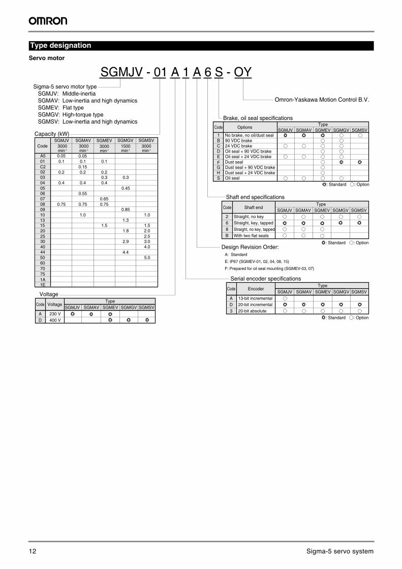
Servo motor
Type designation
Shaft end specificationsType
268B
Straight, no key
Shaft endCode
Straight, key, tappedStraight, no key, tappedWith two flat seats
: Standard : Option
SGMJV - 01 A 1 A 6 S - OYSigma-5 servo motor type SGMJV: Middle-inertia SGMAV: Low-inertia and high dynamics SGMEV: Flat type SGMGV: High-torque type SGMSV: Low-inertia and high dynamics
Design Revision Order: A: Standard
E: IP67 (SGMEV-01, 02, 04, 08, 15)
F: Prepared for oil seal mounting (SGMEV-03, 07)
Capacity (kW)SGMGV SGMSV
3000min-1
1500min-1
SGMJV3000min-1
SGMAV3000min-1
0.050.1
0.4
0.850.75
1.3
A501
0304
0809
13
20
30
44
Code
0.05
0.20.15C2
02
06 0.5505 0.45
07
10
15
25
40
506070751A1E
SGMEV3000min-1
0.1 0.1
0.2 0.20.3 0.3
0.4 0.4
0.650.75 0.75
1.0 1.0
1.5 1.51.8 2.0
2.52.9
4.04.4
5.0
3.0
EncoderCode
: Standard : Option
Serial encoder specificationsType
SGMJV SGMAV SGMGV SGMSVA 13-bit incrementalD 20-bit incremental3 20-bit absolute
SGMEV
SGMJV SGMAV SGMGV SGMSVSGMEV
Omron-Yaskawa Motion Control B.V.
Brake, oil seal specificationsType
No brake, no oil/dust seal
OptionsCodeSGMJV SGMAV SGMGV SGMSVSGMEV
24 VDC brake90 VDC brake
Oil seal + 90 VDC brakeOil seal + 24 VDC brakeDust sealDust seal + 90 VDC brakeDust seal + 24 VDC brakeOil seal
BCDEFGHS
1
: Standard : Option
VoltageCode
VoltageType
SGMJV SGMAV SGMGV SGMSVA 230 VD 400 V
SGMEV
12 Sigma-5 servo system
6 AC servo systems
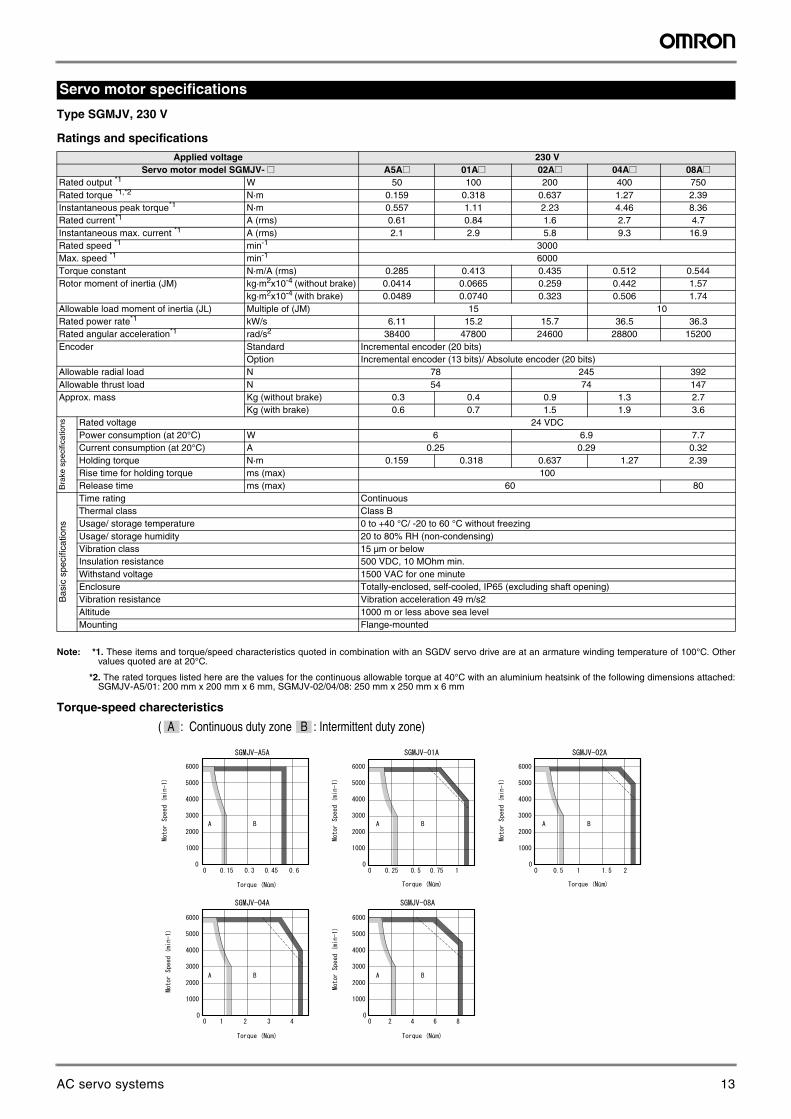
Type SGMJV, 230 V
Ratings and specifications
Note: *1. These items and torque/speed characteristics quoted in combination with an SGDV servo drive are at an armature winding temperature of 100°C. Other values quoted are at 20°C.
*2. The rated torques listed here are the values for the continuous allowable torque at 40°C with an aluminium heatsink of the following dimensions attached: SGMJV-A5/01: 200 mm x 200 mm x 6 mm, SGMJV-02/04/08: 250 mm x 250 mm x 6 mm
Torque-speed charecteristics
Servo motor specifications
Applied voltage 230 VServo motor model SGMJV- @ A5A@ 01A@ 02A@ 04A@ 08A@
Rated output *1 W 50 100 200 400 750Rated torque *1,*2 N·m 0.159 0.318 0.637 1.27 2.39Instantaneous peak torque*1 N·m 0.557 1.11 2.23 4.46 8.36Rated current*1 A (rms) 0.61 0.84 1.6 2.7 4.7Instantaneous max. current *1 A (rms) 2.1 2.9 5.8 9.3 16.9Rated speed *1 min-1 3000Max. speed *1 min-1 6000Torque constant N·m/A (rms) 0.285 0.413 0.435 0.512 0.544Rotor moment of inertia (JM) kg·m2x10-4 (without brake) 0.0414 0.0665 0.259 0.442 1.57
kg·m2x10-4 (with brake) 0.0489 0.0740 0.323 0.506 1.74Allowable load moment of inertia (JL) Multiple of (JM) 15 10Rated power rate*1 kW/s 6.11 15.2 15.7 36.5 36.3Rated angular acceleration*1 rad/s2 38400 47800 24600 28800 15200Encoder Standard Incremental encoder (20 bits)
Option Incremental encoder (13 bits)/ Absolute encoder (20 bits)Allowable radial load N 78 245 392Allowable thrust load N 54 74 147Approx. mass Kg (without brake) 0.3 0.4 0.9 1.3 2.7
Kg (with brake) 0.6 0.7 1.5 1.9 3.6
Bra
ke s
peci
ficat
ions Rated voltage 24 VDC
Power consumption (at 20°C) W 6 6.9 7.7Current consumption (at 20°C) A 0.25 0.29 0.32Holding torque N·m 0.159 0.318 0.637 1.27 2.39Rise time for holding torque ms (max) 100Release time ms (max) 60 80
Bas
ic s
peci
ficat
ions
Time rating ContinuousThermal class Class BUsage/ storage temperature 0 to +40 °C/ -20 to 60 °C without freezingUsage/ storage humidity 20 to 80% RH (non-condensing)Vibration class 15 µm or belowInsulation resistance 500 VDC, 10 MOhm min.Withstand voltage 1500 VAC for one minuteEnclosure Totally-enclosed, self-cooled, IP65 (excluding shaft opening)Vibration resistance Vibration acceleration 49 m/s2Altitude 1000 m or less above sea levelMounting Flange-mounted
( A : Continuous duty zone B : Intermittent duty zone)
û û
û û
û
13AC servo systems
Sigma-5 servo system 7
AC
Ser
vo s
yste
ms
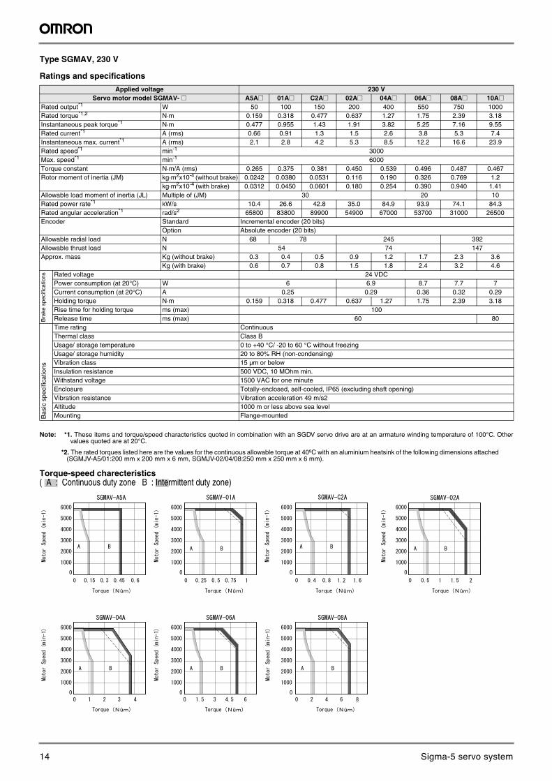
Type SGMAV, 230 V
Ratings and specifications
Note: *1. These items and torque/speed characteristics quoted in combination with an SGDV servo drive are at an armature winding temperature of 100°C. Other values quoted are at 20°C.
*2. The rated torques listed here are the values for the continuous allowable torque at 40ºC with an aluminium heatsink of the following dimensions attached (SGMJV-A5/01:200 mm x 200 mm x 6 mm, SGMJV-02/04/08:250 mm x 250 mm x 6 mm).
Torque-speed charecteristics
Applied voltage 230 VServo motor model SGMAV- @ A5A@ 01A@ C2A@ 02A@ 04A@ 06A@ 08A@ 10A@
Rated output*1 W 50 100 150 200 400 550 750 1000Rated torque*1,2 N·m 0.159 0.318 0.477 0.637 1.27 1.75 2.39 3.18Instantaneous peak torque*1 N·m 0.477 0.955 1.43 1.91 3.82 5.25 7.16 9.55Rated current*1 A (rms) 0.66 0.91 1.3 1.5 2.6 3.8 5.3 7.4Instantaneous max. current*1 A (rms) 2.1 2.8 4.2 5.3 8.5 12.2 16.6 23.9Rated speed*1 min-1 3000Max. speed*1 min-1 6000Torque constant N·m/A (rms) 0.265 0.375 0.381 0.450 0.539 0.496 0.487 0.467Rotor moment of inertia (JM) kg·m2x10-4 (without brake) 0.0242 0.0380 0.0531 0.116 0.190 0.326 0.769 1.2
kg·m2x10-4 (with brake) 0.0312 0.0450 0.0601 0.180 0.254 0.390 0.940 1.41Allowable load moment of inertia (JL) Multiple of (JM) 30 20 10Rated power rate*1 kW/s 10.4 26.6 42.8 35.0 84.9 93.9 74.1 84.3Rated angular acceleration*1 rad/s2 65800 83800 89900 54900 67000 53700 31000 26500Encoder Standard Incremental encoder (20 bits)
Option Absolute encoder (20 bits)Allowable radial load N 68 78 245 392Allowable thrust load N 54 74 147Approx. mass Kg (without brake) 0.3 0.4 0.5 0.9 1.2 1.7 2.3 3.6
Kg (with brake) 0.6 0.7 0.8 1.5 1.8 2.4 3.2 4.6
Bra
ke s
peci
ficat
ions Rated voltage 24 VDC
Power consumption (at 20°C) W 6 6.9 8.7 7.7 7Current consumption (at 20°C) A 0.25 0.29 0.36 0.32 0.29Holding torque N·m 0.159 0.318 0.477 0.637 1.27 1.75 2.39 3.18Rise time for holding torque ms (max) 100Release time ms (max) 60 80
Bas
ic s
peci
ficat
ions
Time rating ContinuousThermal class Class BUsage/ storage temperature 0 to +40 °C/ -20 to 60 °C without freezingUsage/ storage humidity 20 to 80% RH (non-condensing)Vibration class 15 µm or belowInsulation resistance 500 VDC, 10 MOhm min.Withstand voltage 1500 VAC for one minuteEnclosure Totally-enclosed, self-cooled, IP65 (excluding shaft opening)Vibration resistance Vibration acceleration 49 m/s2Altitude 1000 m or less above sea levelMounting Flange-mounted
( A : Continuous duty zone B : Intermittent duty zone)
û
û û û
û û û
14 Sigma-5 servo system
8 AC servo systems
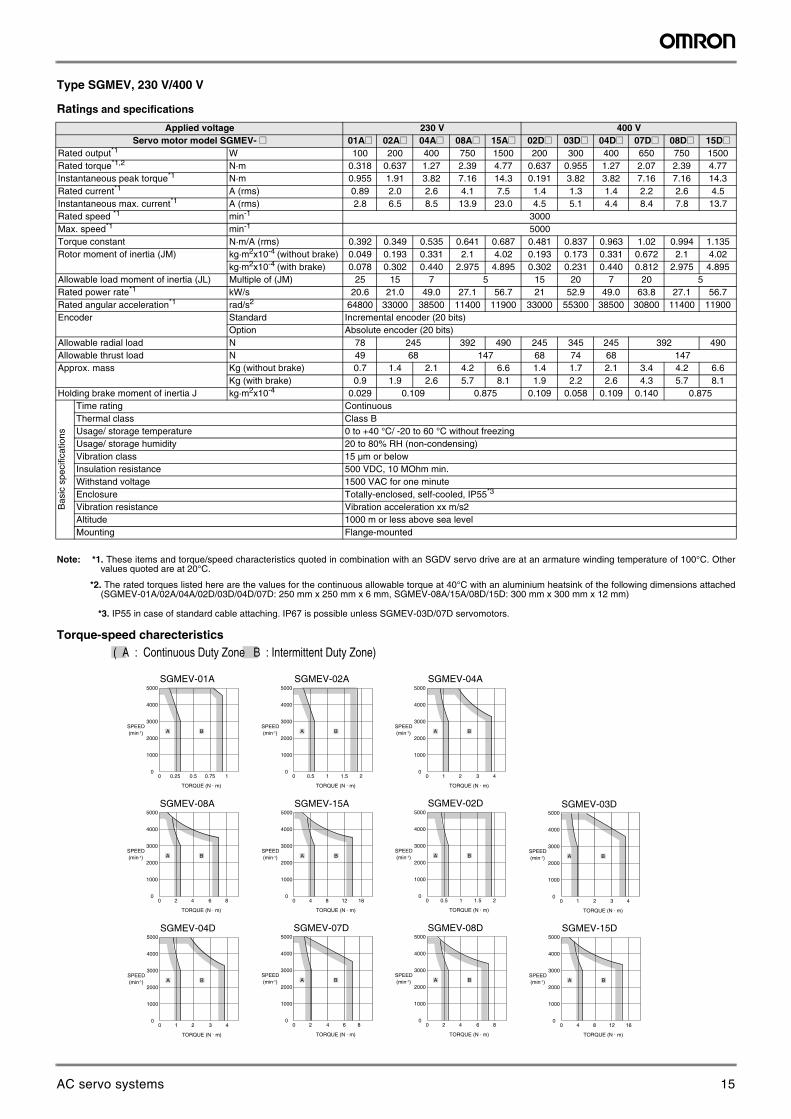
Type SGMEV, 230 V/400 V
Ratings and specifications
Note: *1. These items and torque/speed characteristics quoted in combination with an SGDV servo drive are at an armature winding temperature of 100°C. Other values quoted are at 20°C.
*2. The rated torques listed here are the values for the continuous allowable torque at 40°C with an aluminium heatsink of the following dimensions attached (SGMEV-01A/02A/04A/02D/03D/04D/07D: 250 mm x 250 mm x 6 mm, SGMEV-08A/15A/08D/15D: 300 mm x 300 mm x 12 mm)
*3. IP55 in case of standard cable attaching. IP67 is possible unless SGMEV-03D/07D servomotors.
Torque-speed charecteristics
Applied voltage 230 V 400 VServo motor model SGMEV- @ 01A@ 02A@ 04A@ 08A@ 15A@ 02D@ 03D@ 04D@ 07D@ 08D@ 15D@
Rated output*1 W 100 200 400 750 1500 200 300 400 650 750 1500Rated torque*1,2 N·m 0.318 0.637 1.27 2.39 4.77 0.637 0.955 1.27 2.07 2.39 4.77Instantaneous peak torque*1 N·m 0.955 1.91 3.82 7.16 14.3 0.191 3.82 3.82 7.16 7.16 14.3Rated current*1 A (rms) 0.89 2.0 2.6 4.1 7.5 1.4 1.3 1.4 2.2 2.6 4.5Instantaneous max. current*1 A (rms) 2.8 6.5 8.5 13.9 23.0 4.5 5.1 4.4 8.4 7.8 13.7Rated speed *1 min-1 3000Max. speed*1 min-1 5000Torque constant N·m/A (rms) 0.392 0.349 0.535 0.641 0.687 0.481 0.837 0.963 1.02 0.994 1.135Rotor moment of inertia (JM) kg·m2x10-4 (without brake) 0.049 0.193 0.331 2.1 4.02 0.193 0.173 0.331 0.672 2.1 4.02
kg·m2x10-4 (with brake) 0.078 0.302 0.440 2.975 4.895 0.302 0.231 0.440 0.812 2.975 4.895Allowable load moment of inertia (JL) Multiple of (JM) 25 15 7 5 15 20 7 20 5Rated power rate*1 kW/s 20.6 21.0 49.0 27.1 56.7 21 52.9 49.0 63.8 27.1 56.7Rated angular acceleration*1 rad/s2 64800 33000 38500 11400 11900 33000 55300 38500 30800 11400 11900Encoder Standard Incremental encoder (20 bits)
Option Absolute encoder (20 bits)Allowable radial load N 78 245 392 490 245 345 245 392 490Allowable thrust load N 49 68 147 68 74 68 147Approx. mass Kg (without brake) 0.7 1.4 2.1 4.2 6.6 1.4 1.7 2.1 3.4 4.2 6.6
Kg (with brake) 0.9 1.9 2.6 5.7 8.1 1.9 2.2 2.6 4.3 5.7 8.1Holding brake moment of inertia J kg·m2x10-4 0.029 0.109 0.875 0.109 0.058 0.109 0.140 0.875
Bas
ic s
peci
ficat
ions
Time rating ContinuousThermal class Class BUsage/ storage temperature 0 to +40 °C/ -20 to 60 °C without freezingUsage/ storage humidity 20 to 80% RH (non-condensing)Vibration class 15 µm or belowInsulation resistance 500 VDC, 10 MOhm min.Withstand voltage 1500 VAC for one minuteEnclosure Totally-enclosed, self-cooled, IP55*3
Vibration resistance Vibration acceleration xx m/s2Altitude 1000 m or less above sea levelMounting Flange-mounted
( A : Continuous Duty Zone B : Intermittent Duty Zone)
SGMEV-01A SGMEV-02A SGMEV-04A
SGMEV-08A SGMEV-15A
4000
3000
2000
1000
00 0.25 0.5 0.75 1
5000
SPEED(min-1)
TORQUE (N · m)
A B
4000
3000
2000
1000
00 2 4 6 8
5000
SPEED(min-1)
TORQUE (N · m)
A B
4000
3000
2000
1000
00 4 8 12 16
5000
SPEED(min-1)
TORQUE (N · m)
A B
4000
3000
2000
1000
00 0.5 1 1.5 2
5000
SPEED(min-1)
TORQUE (N · m)
A B
4000
3000
2000
1000
00 1 2 3 4
5000
SPEED(min-1)
TORQUE (N · m)
A B
SGMEV-02D
4000
3000
2000
1000
00 0.5 1 1.5 2
5000
SPEED(min-1)
TORQUE (N · m)
A B
SGMEV-08D
4000
3000
2000
1000
00 2 4 6 8
5000
SPEED(min-1)
TORQUE (N · m)
A B
SGMEV-15D
4000
3000
2000
1000
00 4 8 12 16
5000
SPEED(min-1)
TORQUE (N · m)
A B
SGMEV-04D
4000
3000
2000
1000
00 1 2 3 4
5000
SPEED(min-1)
TORQUE (N · m)
A B
SGMEV-03D
4000
3000
2000
1000
00 1 2 3 4
5000
SPEED(min-1)
TORQUE (N · m)
A B
SGMEV-07D
4000
3000
2000
1000
00 2 4 6 8
5000
SPEED(min-1)
TORQUE (N · m)
A B
15AC servo systems
Sigma-5 servo system 9
AC
Ser
vo s
yste
ms
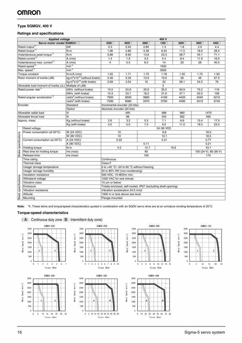
Type SGMGV, 400 V
Ratings and specifications
Note: *1. These items and torque/speed characteristics quoted in combination with an SGDV servo drive are at an armature winding temperature of 20°C.
Torque-speed charecteristics
Applied voltage 400 VServo motor model SGMGV- @ 03D@ 05D@ 09D@ 13D@ 20D@ 30D@ 44D@
Rated output*1 kW 0.3 0.45 0.85 1.3 1.8 2.9 4.4Rated torque*1 N·m 1.96 2.86 5.39 8.34 11.5 18.6 28.4Instantaneous peak torque*1 N·m 5.88 8.92 13.8 23.3 28.7 45.1 71.1Rated current*1 A (rms) 1.4 1.9 3.5 5.4 8.4 11.9 16.5Instantaneous max. current*1 A (rms) 4 5.5 8.5 14 20 28 40.5Rated speed*1 min-1 1500Max. speed*1 min-1 3000Torque constant N·m/A (rms) 1.55 1.71 1.72 1.78 1.50 1.70 1.93Rotor moment of inertia (JM) kg·m2x10-4 (without brake) 2.48 3.33 13.9 19.9 26 46 67.5
kg·m2x10-4 (with brake) 2.69 3.54 16 22 28.1 54.5 76Allowable load moment of inertia (JL) Multiple of (JM) 5Rated power rate*1 kW/s (without brake) 15.5 24.6 20.9 35.0 50.9 75.2 119
kW/s (with brake) 14.3 23.1 18.2 31.6 47.1 63.5 106Rated angular acceleration*1 rad/s2 (without brake) 7900 8590 3880 4190 4420 4040 4210
rad/s2 (with brake) 7290 8080 3370 3790 4090 3410 3740Encoder Standard Incremental encoder (20 bits)
Option Absolute encoder (20 bits)Allowable radial load N 490 686 980 1470Allowable thrust load N 98 343 392 490Approx. mass Kg (without brake) 2.6 3.2 5.5 7.1 8.6 13.4 17.5
Kg (with brake) 4.5 5.0 7.5 9.0 11.0 19.5 23.5
Bra
ke s
peci
ficat
ions
Rated voltage 24 /90 VDCPower consumption (at 20°C) W (24 VDC) 10 9.8 18.5
W (90 VDC) 10 10.1 18.5Current consumption (at 20°C) A (24 VDC) 0.42 0.41 0.77
A (90 VDC) 0.11 0.21Holding torque N·m 4.5 12.7 19.6 43.1Rise time for holding torque ms (max) 80 100 (24 V), 80 (90 V)Release time ms (max) 100 170
Bas
ic s
peci
ficat
ions
Time rating ContinuousThermal class Class FUsage/ storage temperature 0 to +40 °C/ -20 to 60 °C without freezingUsage/ storage humidity 20 to 80% RH (non-condensing)Insulation resistance 500 VDC, 10 MOhm min.Withstand voltage 1500 VAC for one minuteVibration class 15 µm or belowEnclosure Totally-enclosed, self-cooled, IP67 (excluding shaft opening)Vibration resistance Vibration acceleration 24.5 m/s2Altitude 1000 m or less above sea levelMounting Flange-mounted
û
û û û
û û û
( A : Continuous duty zone B : Intermittent duty zone)
16 Sigma-5 servo system
10 AC servo systems
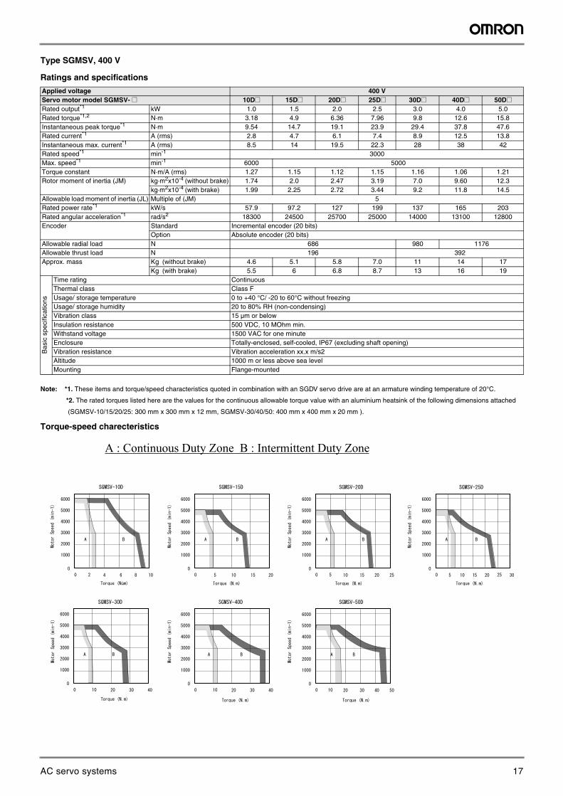
Type SGMSV, 400 V
Ratings and specifications
Note: *1. These items and torque/speed characteristics quoted in combination with an SGDV servo drive are at an armature winding temperature of 20°C.
*2. The rated torques listed here are the values for the continuous allowable torque value with an aluminium heatsink of the following dimensions attached
(SGMSV-10/15/20/25: 300 mm x 300 mm x 12 mm, SGMSV-30/40/50: 400 mm x 400 mm x 20 mm ).
Torque-speed charecteristics
Applied voltage 400 VServo motor model SGMSV- @ 10D@ 15D@ 20D@ 25D@ 30D@ 40D@ 50D@Rated output*1 kW 1.0 1.5 2.0 2.5 3.0 4.0 5.0Rated torque*1,2 N·m 3.18 4.9 6.36 7.96 9.8 12.6 15.8Instantaneous peak torque*1 N·m 9.54 14.7 19.1 23.9 29.4 37.8 47.6Rated current*1 A (rms) 2.8 4.7 6.1 7.4 8.9 12.5 13.8Instantaneous max. current*1 A (rms) 8.5 14 19.5 22.3 28 38 42Rated speed*1 min-1 3000Max. speed*1 min-1 6000 5000Torque constant N·m/A (rms) 1.27 1.15 1.12 1.15 1.16 1.06 1.21Rotor moment of inertia (JM) kg·m2x10-4 (without brake) 1.74 2.0 2.47 3.19 7.0 9.60 12.3
kg·m2x10-4 (with brake) 1.99 2.25 2.72 3.44 9.2 11.8 14.5Allowable load moment of inertia (JL) Multiple of (JM) 5Rated power rate*1 kW/s 57.9 97.2 127 199 137 165 203Rated angular acceleration*1 rad/s2 18300 24500 25700 25000 14000 13100 12800Encoder Standard Incremental encoder (20 bits)
Option Absolute encoder (20 bits)Allowable radial load N 686 980 1176Allowable thrust load N 196 392Approx. mass Kg (without brake) 4.6 5.1 5.8 7.0 11 14 17
Kg (with brake) 5.5 6 6.8 8.7 13 16 19
Bas
ic s
peci
ficat
ions
Time rating ContinuousThermal class Class FUsage/ storage temperature 0 to +40 °C/ -20 to 60°C without freezingUsage/ storage humidity 20 to 80% RH (non-condensing)Vibration class 15 µm or belowInsulation resistance 500 VDC, 10 MOhm min.Withstand voltage 1500 VAC for one minuteEnclosure Totally-enclosed, self-cooled, IP67 (excluding shaft opening)Vibration resistance Vibration acceleration xx.x m/s2Altitude 1000 m or less above sea levelMounting Flange-mounted
A : Continuous Duty Zone B : Intermittent Duty Zone
û
17AC servo systems
Sigma-5 servo system 11
AC
Ser
vo s
yste
ms
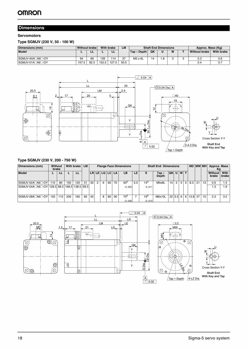
Servomotors
Type SGMJV (230 V, 50 - 100 W)
Type SGMJV (230 V, 200 - 750 W)
Dimensions
Dimensions (mm) Without brake With brake LM Shaft End Dimensions Approx. Mass (Kg)Model L LL L LL Tap × Depth QK U W T Without brake With brake
SGMJV-A5A@A6@-OY 94 69 139 114 37 M3 x 6L 14 1.8 3 3 0.3 0.6SGMJV-01A@A6@-OY 107.5 82.5 152.5 127.5 50.5 0.4 0.7
Dimensions (mm) Without brake
With brake LM Flange Face Dimensions Shaft End Dimensions MD MW MH Approx. Mass Kg
Model L LL L LL LR LE LG LC LA LB LZ S Tap × Depth
QK U W T Without brake
With brake
SGMJV-02A@A6@-OY 110 80 150 120 51 30 3 6 60 70 500
-0..025
5.5 140
-0..011
M5x8L 14 3 5 5 8.3 21 13 0.9 1.5SGMJV-04A@A6@-OY 128.5 98.5 168.5 138.5 69.5 1.3 1.9
SGMJV-08A@A6@-OY 155 115 200 160 85 40 8 80 90 700
-0..030
7 190
-0..013
M6x10L 22 3.5 6 6 13.8 27 15 2.3 3.2
Y
YCross Section Y-Y
Shaft EndWith Key and Tap
46 Dia.
¡40
L
LM
20
2.5
25
QK
LL
T
6.1
19
20.5
14
172
Dia
.30
12
W
U
8D
ia.
5
0.02
A
0.04 A
A
Tap × Depth
2-4.3 Dia.
0.04 Dia.
0 − 0.0
09
0 − 0.0
21
Y
YCross Section Y-Y
Shaft EndWith Key and Tap
21171.5LM
L
QK
S D
ia.
MH
MW
¡LC
LB D
ia.
LGLE
LRLL
MD20.5
14
T
W
U
LA Dia.
0.04 A
0.02
0.04 Dia. A
A Tap × Depth 4-LZ Dia.
18 Sigma-5 servo system
12 AC servo systems
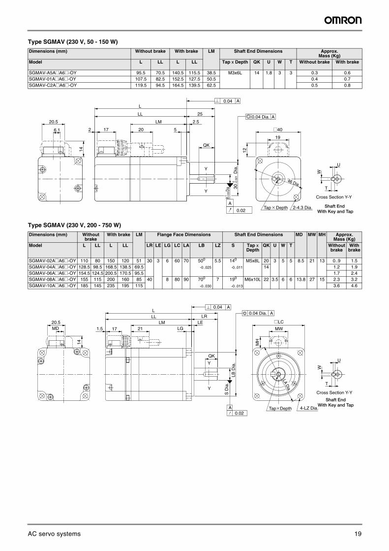
Type SGMAV (230 V, 50 - 150 W)
Type SGMAV (230 V, 200 - 750 W)
Dimensions (mm) Without brake With brake LM Shaft End Dimensions Approx.Mass (Kg)
Model L LL L LL Tap x Depth QK U W T Without brake With brake
SGMAV-A5A@A6@-OY 95.5 70.5 140.5 115.5 38.5 M3x6L 14 1.8 3 3 0.3 0.6SGMAV-01A@A6@-OY 107.5 82.5 152.5 127.5 50.5 0.4 0.7SGMAV-C2A@A6@-OY 119.5 94.5 164.5 139.5 62.5 0.5 0.8
Dimensions (mm) Without brake
With brake LM Flange Face Dimensions Shaft End Dimensions MD MW MH Approx.Mass (Kg)
Model L LL L LL LR LE LG LC LA LB LZ S Tap x Depth
QK U W T Without brake
With brake
SGMAV-02A@A6@-OY 110 80 150 120 51 30 3 6 60 70 500
-0..025
5.5 140
-0..011
M5x8L 20 3 5 5 8.5 21 13 0..9 1.5SGMAV-04A@A6@-OY 128.5 98.5 168.5 138.5 69.5 14 1.2 1.9SGMAV-06A@A6@-OY 154.5 124.5 200.5 170.5 95.5 1.7 2.4SGMAV-08A@A6@-OY 155 115 200 160 85 40 8 80 90 700
-0..030
7 190
-0..013
M6x10L 22 3.5 6 6 13.8 27 15 2.3 3.2SGMAV-10A@A6@-OY 185 145 235 195 115 3.6 4.6
Y
YCross Section Y-Y
Shaft End With Key and Tap
46 Dia.
¡40
L
LM
20
2.5
25
QK
LL
T
6.1
19
20.5
14
172
12
W
U
30D
ia.
0 -0.0
21
8Di
a.0 -0 .
009
5
0.02
A
0.04 A
ATap × Depth 2-4.3 Dia.
0.04 Dia.
Y
Y
21171.5LM
L
QK
S D
ia.
LA Dia.
MH
MW
¡LC
LB D
ia.
LGLE
LRLL
MD20.5
14
0.04 A
0.02Tap×Depth 4-LZ Dia.
0.04 Dia. A
A
Cross Section Y-Y
Shaft EndWith Key and Tap
T
W
U
19AC servo systems
Sigma-5 servo system 13
AC
Ser
vo s
yste
ms
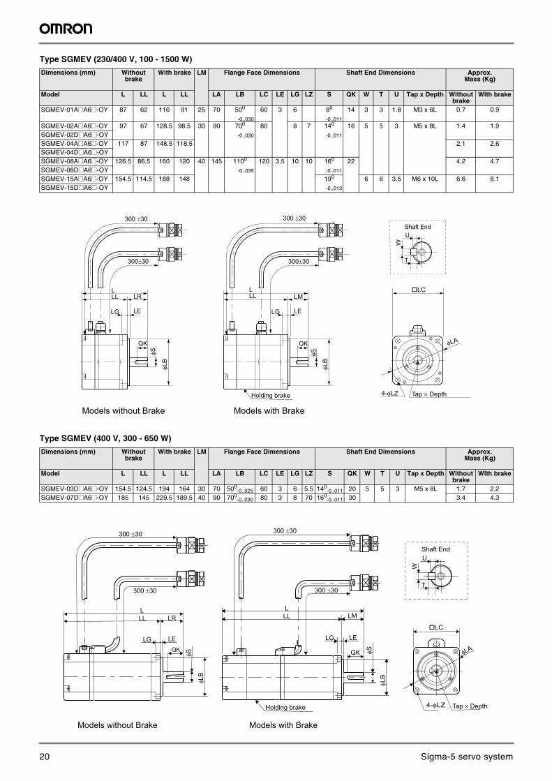
Type SGMEV (230/400 V, 100 - 1500 W)
Type SGMEV (400 V, 300 - 650 W)
Dimensions (mm) Without brake
With brake LM Flange Face Dimensions Shaft End Dimensions Approx. Mass (Kg)
Model L LL L LL LA LB LC LE LG LZ S QK W T U Tap x Depth Without brake
With brake
SGMEV-01A@A6@-OY 87 62 116 91 25 70 500
-0..030
60 3 6 80
-0..011
14 3 3 1.8 M3 x 6L 0.7 0.9
SGMEV-02A@A6@-OY 97 67 128.5 98.5 30 90 700
-0..030
80 8 7 140
-0..011
16 5 5 3 M5 x 8L 1.4 1.9SGMEV-02D@A6@-OYSGMEV-04A@A6@-OY 117 87 148.5 118.5 2.1 2.6SGMEV-04D@A6@-OYSGMEV-08A@A6@-OY 126.5 86.5 160 120 40 145 1100
-0..035
120 3.5 10 10 160
-0..011
22 4.2 4.7SGMEV-08D@A6@-OYSGMEV-15A@A6@-OY 154.5 114.5 188 148 190
-0..013
6 6 3.5 M6 x 10L 6.6 8.1SGMEV-15D@A6@-OY
Dimensions (mm) Without brake
With brake LM Flange Face Dimensions Shaft End Dimensions Approx. Mass (Kg)
Model L LL L LL LA LB LC LE LG LZ S QK W T U Tap x Depth Without brake
With brake
SGMEV-03D@A6@-OY 154.5 124.5 194 164 30 70 500-0..025 60 3 6 5.5 140
-0..011 20 5 5 3 M5 x 8L 1.7 2.2SGMEV-07D@A6@-OY 185 145 229.5 189.5 40 90 700
-0..030 80 3 8 70 160-0..011 30 3.4 4.3
φLA
Tap × Depth4-φLZ
300 ±30
300±30
φS
φLB
QK
LLL
LG
LR
LE
300±30
φS
φLB
QK
LLL
LG
LM
LE
LC
Holding brake
Models with BrakeModels without Brake
T
U
W
Shaft End300 ±30
φLA
Tap × Depth4-φLZ
T
U
W
LLL LR
LELGQK
φS
300 ±30
300 ±30
Shaft End
φLB
300 ±30
300 ±30
Holding brake
φLB
QK φS
LLL LM
LG LELC
Models with BrakeModels without Brake
20 Sigma-5 servo system
14 AC servo systems
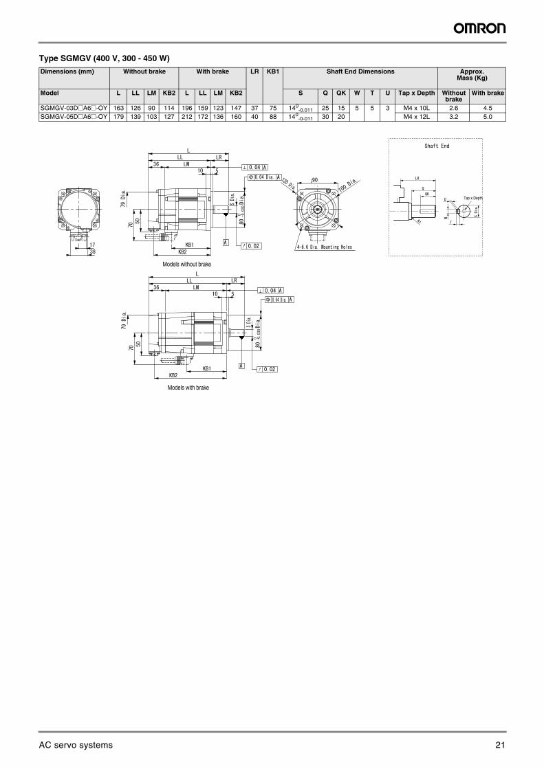
Type SGMGV (400 V, 300 - 450 W)
Dimensions (mm) Without brake With brake LR KB1 Shaft End Dimensions Approx. Mass (Kg)
Model L LL LM KB2 L LL LM KB2 S Q QK W T U Tap x Depth Without brake
With brake
SGMGV-03D@A6@-OY 163 126 90 114 196 159 123 147 37 75 140-0.011 25 15 5 5 3 M4 x 10L 2.6 4.5
SGMGV-05D@A6@-OY 179 139 103 127 212 172 136 160 40 88 140-0-011 30 20 M4 x 12L 3.2 5.0
¡
Models without brake
Models with brake
Tap x Depth
21AC servo systems
Sigma-5 servo system 15
AC
Ser
vo s
yste
ms
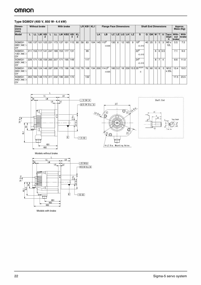
Type SGMGV (400 V, 850 W- 4.4 kW)
Dimen-sions(mm)
Without brake With brake LR KB1 KL1 Flange Face Dimensions Shaft End Dimensions Approx. Mass (Kg)
Model L LL LM KB2
L LL LM KB2 KB3
KL3
LA LB LC LE LG LH LZ S Q QK W T U Tap x Dept
h
With-out
brake
With brake
SGMGV-09D@A6@-OY
195 137 101 125 231 173 137 161 115 80 58 83 104 145 1100
-0.035
130 6 12 165 9 190
-0..013
40 25 5 5 3 M5 x 12L
5.5 7.5
SGMGV-13D@A6@-OY
211 153 117 141 247 189 153 177 131 99 220
-0..013
6 6 3.5 7.1 9.0
SGMGV-20D@A6@-OY
229 171 135 159 265 207 171 195 149 117 240
-0..013
8 7 4 8.6 11.0
SGMGV-30D@A6@-OY
239 160 124 148 287 208 172 196 148 110 79 108 134 200 114.30
-0.025
180 3.2 18 230 13.5 35+0.01
0
76 60 10 8 5 M12 x 25L
13.4 19.5
SGMGV-44D@A6@-OY
263 184 148 172 311 232 196 220 172 132 17.5 23.5
¡
Models without brake
Models with brake
Tap x Depth
22 Sigma-5 servo system
16 AC servo systems
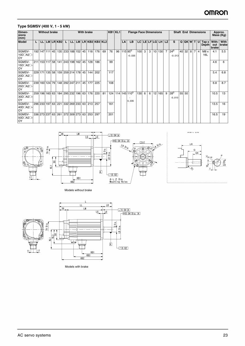
Type SGMSV (400 V, 1 - 5 kW)
Dimen-sions(mm)
Without brake With brake KB1 KL1 Flange Face Dimensions Shaft End Dimensions Approx. Mass (Kg)
Model L LL LM LR KB2 L LL LM LR KB2 KB3 KL2 LA LB LC LE LF LG LH LZ S Q QK W T U Tap x Depth
With-out
brake
With brake
SGMSV-10D@A2@-OY
192 147 111 45 135 233 188 152 45 118 176 69 76 96 115 950
-0..035
100 3 3 10 130 7 240
-0..013
40 32 8 7 4 M8 x 16L
4.1 5.5
SGMSV-15D@A2@-OY
211 153 117 58 141 243 198 162 45 128 186 99 4.6 6
SGMSV-20D@A2@-OY
229 171 135 58 159 259 214 178 45 144 202 117 5.4 6.8
SGMSV-25D@A2@-OY
239 160 124 79 148 292 247 211 45 177 225 108 6.8 8.7
SGMSV-30D@A2@-OY
259 196 160 63 184 295 232 196 63 176 220 81 124 114 145 1100
-0..035
130 6 6 12 165 9 280
-0..013
55 50 10.5 13
SGMSV-40D@A2@-OY
296 233 197 63 221 332 269 233 63 213 257 161 13.5 16
SGMSV-50D@A2@-OY
336 273 237 63 261 372 309 273 63 253 297 201 16.5 19
Models without brake
Models with brake
LR
QQK
U
R1
P
T
W S D
ia.
23AC servo systems
Sigma-5 servo system 17
AC
Ser
vo s
yste
ms
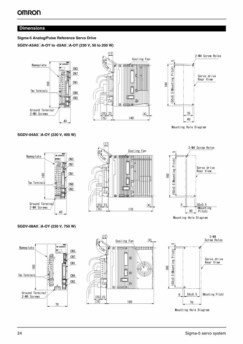
Dimensions
Sigma-5 Analog/Pulse Reference Servo Drive
SGDV-A5A0@A-OY to -02A0@A-OY (230 V, 50 to 200 W)
SGDV-04A0@A-OY (230 V, 400 W)
SGDV-08A0@A-OY (230 V, 750 W)
±±
±
±
±
24 Sigma-5 servo system
18 AC servo systems
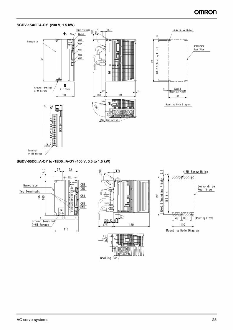
SGDV-15A0@A-OY (230 V, 1.5 kW)
SGDV-05D0@A-OY to -15D0@A-OY (400 V, 0.5 to 1.5 kW) ±
±
±
±
25AC servo systems
Sigma-5 servo system 19
AC
Ser
vo s
yste
ms
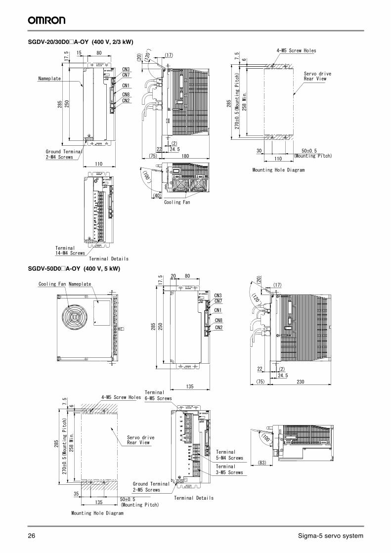
SGDV-20/30D0@A-OY (400 V, 2/3 kW)
SGDV-50D0@A-OY (400 V, 5 kW)
±
±
±
±
26 Sigma-5 servo system
20 AC servo systems
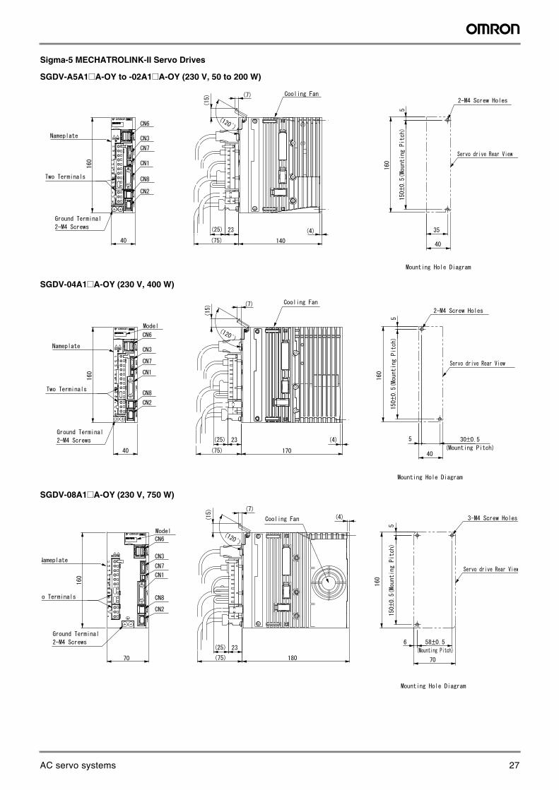
Sigma-5 MECHATROLINK-II Servo Drives
SGDV-A5A1@A-OY to -02A1@A-OY (230 V, 50 to 200 W)
SGDV-04A1@A-OY (230 V, 400 W)
SGDV-08A1@A-OY (230 V, 750 W)
±±
±
±
±
27AC servo systems
Sigma-5 servo system 21
AC
Ser
vo s
yste
ms
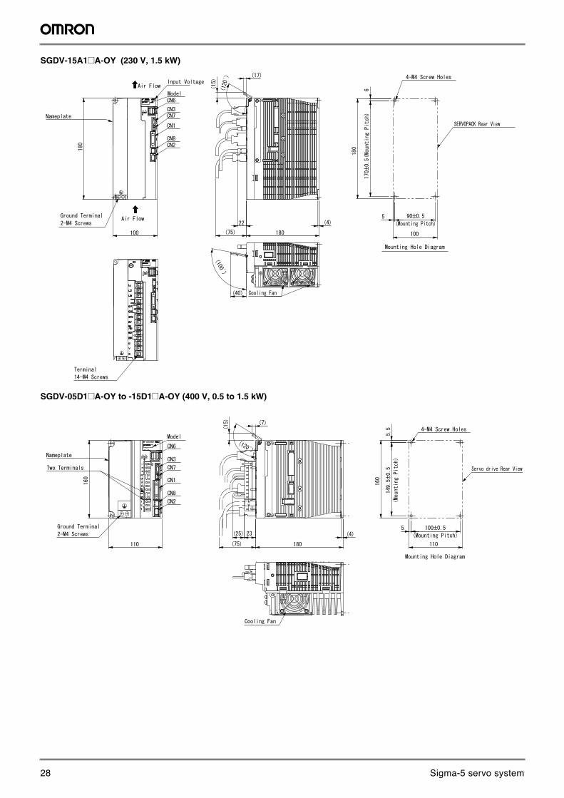
SGDV-15A1@A-OY (230 V, 1.5 kW)
SGDV-05D1@A-OY to -15D1@A-OY (400 V, 0.5 to 1.5 kW)
±
±
±
±
28 Sigma-5 servo system
22 AC servo systems
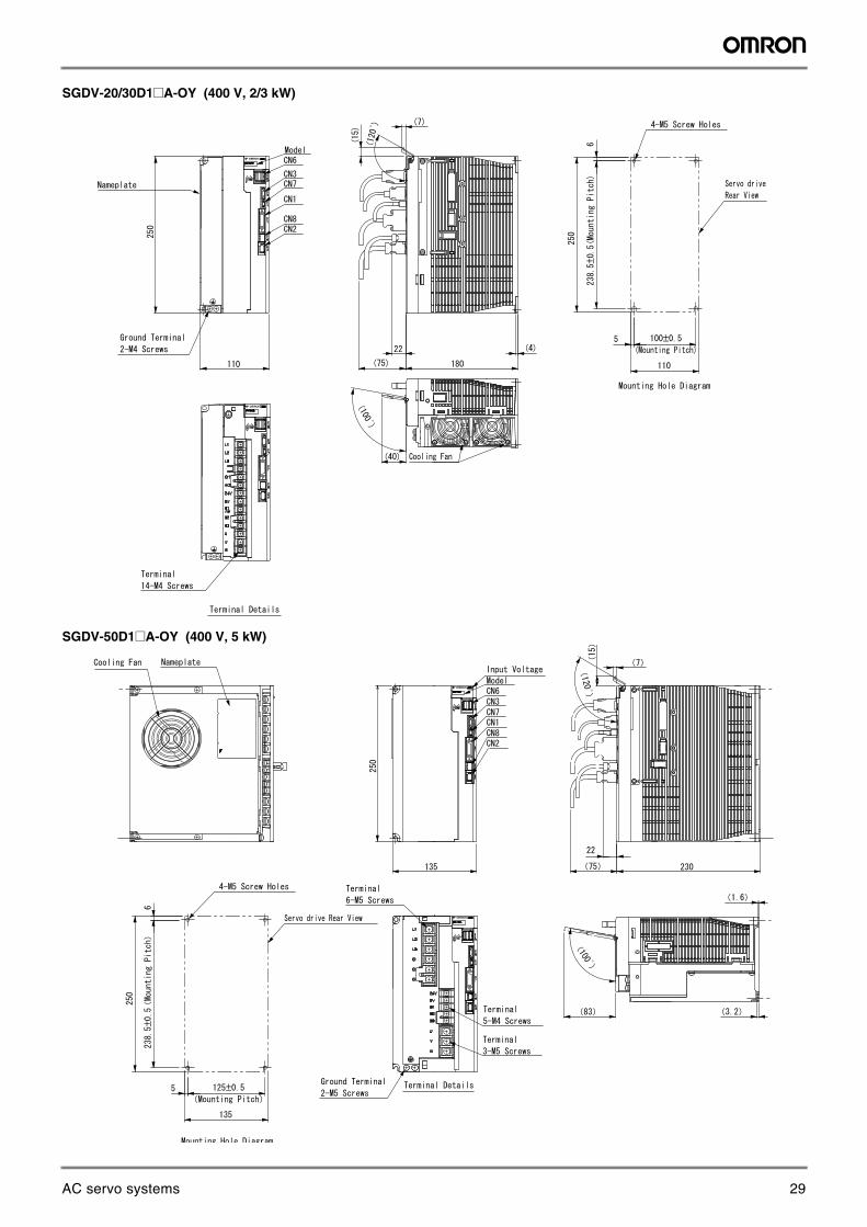
SGDV-20/30D1@A-OY (400 V, 2/3 kW)
SGDV-50D1@A-OY (400 V, 5 kW)
±
±
±
±
29AC servo systems
Sigma-5 servo system 23
AC
Ser
vo s
yste
ms
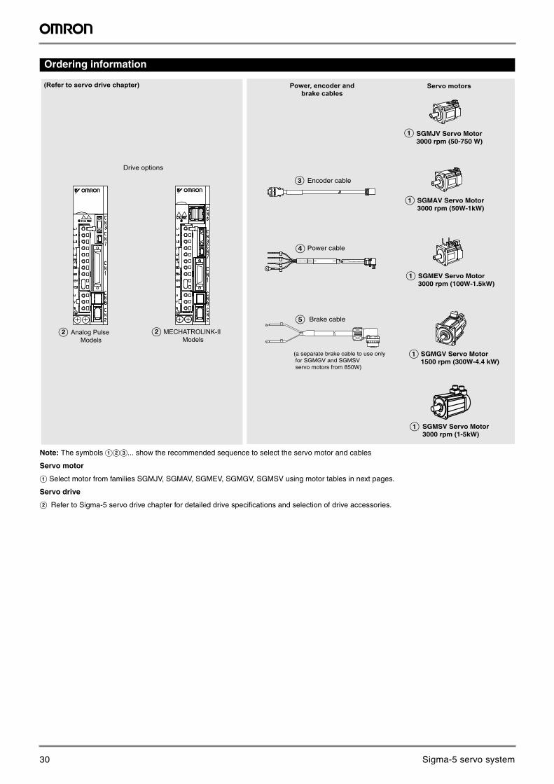
Ordering information
Note: The symbols ABC... show the recommended sequence to select the servo motor and cables
Servo motor
A Select motor from families SGMJV, SGMAV, SGMEV, SGMGV, SGMSV using motor tables in next pages.
Servo drive
B Refer to Sigma-5 servo drive chapter for detailed drive specifications and selection of drive accessories.
B Analog Pulse Models
B MECHATROLINK-II Models
Drive options
(Refer to servo drive chapter)
E Brake cable
Power, encoder and brake cables
C
D
Encoder cable
Power cable
A SGMEV Servo Motor 3000 rpm (100W-1.5kW)
A SGMGV Servo Motor1500 rpm (300W-4.4 kW)
A
A
SGMJV Servo Motor 3000 rpm (50-750 W)
SGMAV Servo Motor 3000 rpm (50W-1kW)
A SGMSV Servo Motor3000 rpm (1-5kW)
(a separate brake cable to use only for SGMGV and SGMSV servo motors from 850W)
Servo motors
30 Sigma-5 servo system
24 AC servo systems
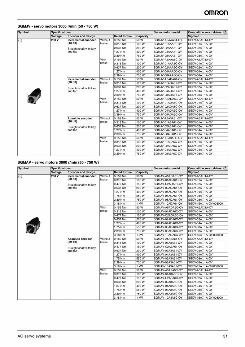
SGMJV - servo motors 3000 r/min (50 - 750 W)
SGMAV - servo motors 3000 r/min (50 - 750 W)
Symbol Specifications Servo motor model Compatible servo drives BVoltage Encoder and design Rated torque Capacity Sigma-5
A 230 V Incremental encoder(13 bit)
Straight shaft with key and tap
Without brake
0.159 Nm 50 W SGMJV-A5AAA61-OY [email protected] Nm 100 W SGMJV-01AAA61-OY [email protected] Nm 200 W SGMJV-02AAA61-OY [email protected] Nm 400 W SGMJV-04AAA61-OY [email protected] Nm 750 W SGMJV-08AAA61-OY SGDV-08A@1A-OY
With brake
0.159 Nm 50 W SGMJV-A5AAA6C-OY [email protected] Nm 100 W SGMJV-01AAA6C-OY [email protected] Nm 200 W SGMJV-02AAA6C-OY [email protected] Nm 400 W SGMJV-04AAA6C-OY [email protected] Nm 750 W SGMJV-08AAA6C-OY SGDV-08A@1A-OY
Incremental encoder(20 bit)
Straight shaft with key and tap
Without brake
0.159 Nm 50 W SGMJV-A5ADA61-OY [email protected] Nm 100 W SGMJV-01ADA61-OY [email protected] Nm 200 W SGMJV-02ADA61-OY [email protected] Nm 400 W SGMJV-04ADA61-OY [email protected] Nm 750 W SGMJV-08ADA61-OY SGDV-08A@1A-OY
With brake
0.159 Nm 50 W SGMJV-A5ADA6C-OY [email protected] Nm 100 W SGMJV-01ADA6C-OY [email protected] Nm 200 W SGMJV-02ADA6C-OY [email protected] Nm 400 W SGMJV-04ADA6C-OY [email protected] Nm 750 W SGMJV-08ADA6C-OY SGDV-08A@1A-OY
Absolute encoder(20 bit)
Straight shaft with key and tap
Without brake
0.159 Nm 50 W SGMJV-A5A3A61-OY [email protected] Nm 100 W SGMJV-01A3A61-OY [email protected] Nm 200 W SGMJV-02A3A61-OY [email protected] Nm 400 W SGMJV-04A3A61-OY [email protected] Nm 750 W SGMJV-08A3A61-OY SGDV-08A@1A-OY
With brake
0.159 Nm 50 W SGMJV-A5A3A6C-OY [email protected] Nm 100 W SGMJV-01A3A6C-OY [email protected] Nm 200 W SGMJV-02A3A6C-OY [email protected] Nm 400 W SGMJV-04A3A6C-OY [email protected] Nm 750 W SGMJV-08A3A6C-OY SGDV-08A@1A-OY
Symbol Specifications Servo motor model Compatible servo drives BVoltage Encoder and design Rated torque Capacity Sigma-5
A 230 V Incremental encoder(20 bit)
Straight shaft with key and tap
Without brake
0.159 Nm 50 W SGMAV-A5ADA61-OY [email protected] Nm 100 W SGMAV-01ADA61-OY [email protected] Nm 150 W SGMAV-C2ADA61-OY [email protected] Nm 200 W SGMAV-02ADA61-OY [email protected] Nm 400 W SGMAV-04ADA61-OY [email protected] Nm 550 W SGMAV-06ADA61-OY [email protected] Nm 750 W SGMAV-08ADA61-OY [email protected] Nm 1 kW SGMAV-10ADA61-OY SGDV-15A@1A-OY-008000
With brake
0.159 Nm 50 W SGMAV-A5ADA6C-OY [email protected] Nm 100 W SGMAV-01ADA6C-OY [email protected] Nm 150 W SGMAV-C2ADA6C-OY [email protected] Nm 200 W SGMAV-02ADA6C-OY [email protected] Nm 400 W SGMAV-04ADA6C-OY [email protected] Nm 550 W SGMAV-06ADA6C-OY [email protected] Nm 750 W SGMAV-08ADA6C-OY [email protected] Nm 1 kW SGMAV-10ADA6C-OY SGDV-15A@1A-OY-008000
Absolute encoder(20 bit)
Straight shaft with key and tap
Without brake
0.159 Nm 50 W SGMAV-A5A3A61-OY [email protected] Nm 100 W SGMAV-01A3A61-OY [email protected] Nm 150 W SGMAV-C2A3A61-OY [email protected] Nm 200 W SGMAV-02A3A61-OY [email protected] Nm 400 W SGMAV-04A3A61-OY [email protected] Nm 550 W SGMAV-06A3A61-OY [email protected] Nm 750 W SGMAV-08A3A61-OY [email protected] Nm 1 kW SGMAV-10A3A61-OY SGDV-15A@1A-OY-008000
With brake
0.159 Nm 50 W SGMAV-A5A3A6C-OY [email protected] Nm 100 W SGMAV-01A3A6C-OY [email protected] Nm 150 W SGMAV-C2A3A6C-OY [email protected] Nm 200 W SGMAV-02A3A6C-OY [email protected] Nm 400 W SGMAV-04A3A6C-OY [email protected] Nm 550 W SGMAV-06A3A6C-OY [email protected] Nm 750 W SGMAV-08A3A6C-OY [email protected] Nm 1 kW SGMAV-10A3A6C-OY SGDV-15A@1A-OY-008000
31AC servo systems
Sigma-5 servo system 25
AC
Ser
vo s
yste
ms
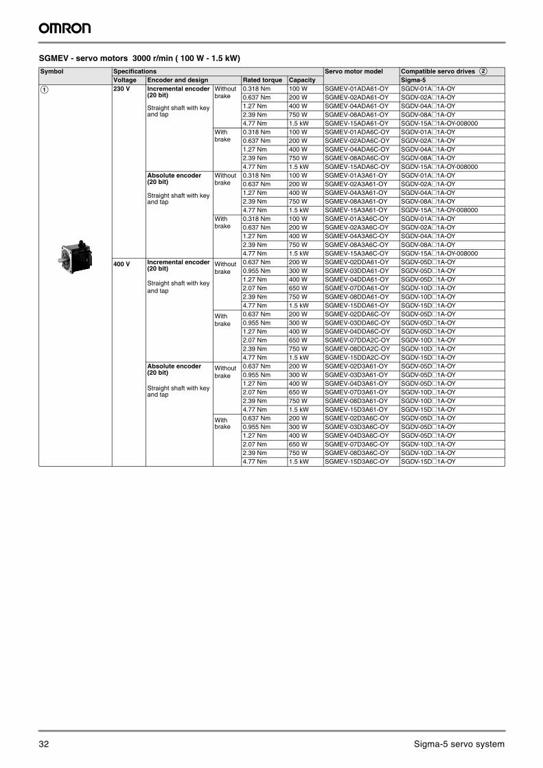
SGMEV - servo motors 3000 r/min ( 100 W - 1.5 kW)
Symbol Specifications Servo motor model Compatible servo drives BVoltage Encoder and design Rated torque Capacity Sigma-5
A 230 V Incremental encoder(20 bit)
Straight shaft with key and tap
Without brake
0.318 Nm 100 W SGMEV-01ADA61-OY [email protected] Nm 200 W SGMEV-02ADA61-OY [email protected] Nm 400 W SGMEV-04ADA61-OY [email protected] Nm 750 W SGMEV-08ADA61-OY [email protected] Nm 1.5 kW SGMEV-15ADA61-OY SGDV-15A@1A-OY-008000
With brake
0.318 Nm 100 W SGMEV-01ADA6C-OY [email protected] Nm 200 W SGMEV-02ADA6C-OY [email protected] Nm 400 W SGMEV-04ADA6C-OY [email protected] Nm 750 W SGMEV-08ADA6C-OY [email protected] Nm 1.5 kW SGMEV-15ADA6C-OY SGDV-15A@1A-OY-008000
Absolute encoder(20 bit)
Straight shaft with key and tap
Without brake
0.318 Nm 100 W SGMEV-01A3A61-OY [email protected] Nm 200 W SGMEV-02A3A61-OY [email protected] Nm 400 W SGMEV-04A3A61-OY [email protected] Nm 750 W SGMEV-08A3A61-OY [email protected] Nm 1.5 kW SGMEV-15A3A61-OY SGDV-15A@1A-OY-008000
With brake
0.318 Nm 100 W SGMEV-01A3A6C-OY [email protected] Nm 200 W SGMEV-02A3A6C-OY [email protected] Nm 400 W SGMEV-04A3A6C-OY [email protected] Nm 750 W SGMEV-08A3A6C-OY [email protected] Nm 1.5 kW SGMEV-15A3A6C-OY SGDV-15A@1A-OY-008000
400 V Incremental encoder(20 bit)
Straight shaft with key and tap
Without brake
0.637 Nm 200 W SGMEV-02DDA61-OY [email protected] Nm 300 W SGMEV-03DDA61-OY [email protected] Nm 400 W SGMEV-04DDA61-OY [email protected] Nm 650 W SGMEV-07DDA61-OY [email protected] Nm 750 W SGMEV-08DDA61-OY [email protected] Nm 1.5 kW SGMEV-15DDA61-OY SGDV-15D@1A-OY
With brake
0.637 Nm 200 W SGMEV-02DDA6C-OY [email protected] Nm 300 W SGMEV-03DDA6C-OY [email protected] Nm 400 W SGMEV-04DDA6C-OY [email protected] Nm 650 W SGMEV-07DDA2C-OY [email protected] Nm 750 W SGMEV-08DDA2C-OY [email protected] Nm 1.5 kW SGMEV-15DDA2C-OY SGDV-15D@1A-OY
Absolute encoder(20 bit)
Straight shaft with key and tap
Without brake
0.637 Nm 200 W SGMEV-02D3A61-OY [email protected] Nm 300 W SGMEV-03D3A61-OY [email protected] Nm 400 W SGMEV-04D3A61-OY [email protected] Nm 650 W SGMEV-07D3A61-OY [email protected] Nm 750 W SGMEV-08D3A61-OY [email protected] Nm 1.5 kW SGMEV-15D3A61-OY SGDV-15D@1A-OY
With brake
0.637 Nm 200 W SGMEV-02D3A6C-OY [email protected] Nm 300 W SGMEV-03D3A6C-OY [email protected] Nm 400 W SGMEV-04D3A6C-OY [email protected] Nm 650 W SGMEV-07D3A6C-OY [email protected] Nm 750 W SGMEV-08D3A6C-OY [email protected] Nm 1.5 kW SGMEV-15D3A6C-OY SGDV-15D@1A-OY
32 Sigma-5 servo system
26 AC servo systems
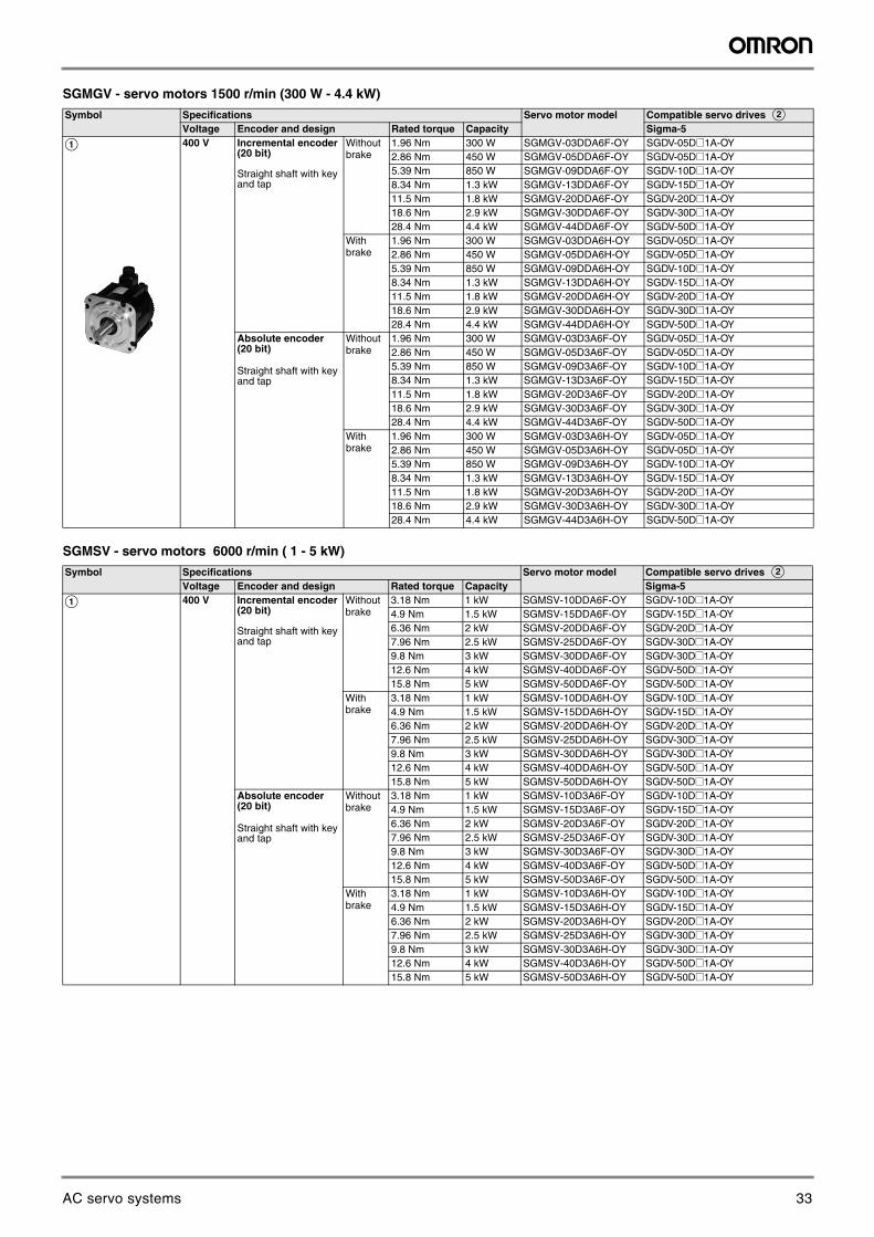
SGMGV - servo motors 1500 r/min (300 W - 4.4 kW)
SGMSV - servo motors 6000 r/min ( 1 - 5 kW)
Symbol Specifications Servo motor model Compatible servo drives BVoltage Encoder and design Rated torque Capacity Sigma-5
A 400 V Incremental encoder(20 bit)
Straight shaft with key and tap
Without brake
1.96 Nm 300 W SGMGV-03DDA6F-OY [email protected] Nm 450 W SGMGV-05DDA6F-OY [email protected] Nm 850 W SGMGV-09DDA6F-OY [email protected] Nm 1.3 kW SGMGV-13DDA6F-OY [email protected] Nm 1.8 kW SGMGV-20DDA6F-OY [email protected] Nm 2.9 kW SGMGV-30DDA6F-OY [email protected] Nm 4.4 kW SGMGV-44DDA6F-OY SGDV-50D@1A-OY
With brake
1.96 Nm 300 W SGMGV-03DDA6H-OY [email protected] Nm 450 W SGMGV-05DDA6H-OY [email protected] Nm 850 W SGMGV-09DDA6H-OY [email protected] Nm 1.3 kW SGMGV-13DDA6H-OY [email protected] Nm 1.8 kW SGMGV-20DDA6H-OY [email protected] Nm 2.9 kW SGMGV-30DDA6H-OY [email protected] Nm 4.4 kW SGMGV-44DDA6H-OY SGDV-50D@1A-OY
Absolute encoder(20 bit)
Straight shaft with key and tap
Without brake
1.96 Nm 300 W SGMGV-03D3A6F-OY [email protected] Nm 450 W SGMGV-05D3A6F-OY [email protected] Nm 850 W SGMGV-09D3A6F-OY [email protected] Nm 1.3 kW SGMGV-13D3A6F-OY [email protected] Nm 1.8 kW SGMGV-20D3A6F-OY [email protected] Nm 2.9 kW SGMGV-30D3A6F-OY [email protected] Nm 4.4 kW SGMGV-44D3A6F-OY SGDV-50D@1A-OY
With brake
1.96 Nm 300 W SGMGV-03D3A6H-OY [email protected] Nm 450 W SGMGV-05D3A6H-OY [email protected] Nm 850 W SGMGV-09D3A6H-OY [email protected] Nm 1.3 kW SGMGV-13D3A6H-OY [email protected] Nm 1.8 kW SGMGV-20D3A6H-OY [email protected] Nm 2.9 kW SGMGV-30D3A6H-OY [email protected] Nm 4.4 kW SGMGV-44D3A6H-OY SGDV-50D@1A-OY
Symbol Specifications Servo motor model Compatible servo drives BVoltage Encoder and design Rated torque Capacity Sigma-5
A 400 V Incremental encoder(20 bit)
Straight shaft with key and tap
Without brake
3.18 Nm 1 kW SGMSV-10DDA6F-OY [email protected] Nm 1.5 kW SGMSV-15DDA6F-OY [email protected] Nm 2 kW SGMSV-20DDA6F-OY [email protected] Nm 2.5 kW SGMSV-25DDA6F-OY [email protected] Nm 3 kW SGMSV-30DDA6F-OY [email protected] Nm 4 kW SGMSV-40DDA6F-OY [email protected] Nm 5 kW SGMSV-50DDA6F-OY SGDV-50D@1A-OY
With brake
3.18 Nm 1 kW SGMSV-10DDA6H-OY [email protected] Nm 1.5 kW SGMSV-15DDA6H-OY [email protected] Nm 2 kW SGMSV-20DDA6H-OY [email protected] Nm 2.5 kW SGMSV-25DDA6H-OY [email protected] Nm 3 kW SGMSV-30DDA6H-OY [email protected] Nm 4 kW SGMSV-40DDA6H-OY [email protected] Nm 5 kW SGMSV-50DDA6H-OY SGDV-50D@1A-OY
Absolute encoder(20 bit)
Straight shaft with key and tap
Without brake
3.18 Nm 1 kW SGMSV-10D3A6F-OY [email protected] Nm 1.5 kW SGMSV-15D3A6F-OY [email protected] Nm 2 kW SGMSV-20D3A6F-OY [email protected] Nm 2.5 kW SGMSV-25D3A6F-OY [email protected] Nm 3 kW SGMSV-30D3A6F-OY [email protected] Nm 4 kW SGMSV-40D3A6F-OY [email protected] Nm 5 kW SGMSV-50D3A6F-OY SGDV-50D@1A-OY
With brake
3.18 Nm 1 kW SGMSV-10D3A6H-OY [email protected] Nm 1.5 kW SGMSV-15D3A6H-OY [email protected] Nm 2 kW SGMSV-20D3A6H-OY [email protected] Nm 2.5 kW SGMSV-25D3A6H-OY [email protected] Nm 3 kW SGMSV-30D3A6H-OY [email protected] Nm 4 kW SGMSV-40D3A6H-OY [email protected] Nm 5 kW SGMSV-50D3A6H-OY SGDV-50D@1A-OY
33AC servo systems
Sigma-5 servo system 27
AC
Ser
vo s
yste
ms
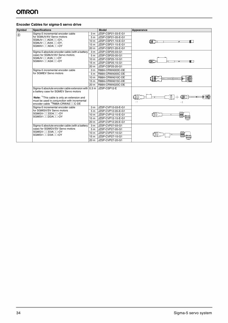
Encoder Cables for sigma-5 servo drive
Symbol Specifications Model Appearance
C Sigma-5 incremental encoder cable for SGMJV/AV Servo motorsSGMJV-@@ADA@@-OY, SGMJV-@@AAA@@-OY, SGMAV-@@ADA@@-OY
3 m JZSP-CSP21-03-E-G15 m JZSP-CSP21-05-E-G1
10 m JZSP-CSP21-10-E-G115 m JZSP-CSP21-15-E-G120 m JZSP-CSP21-20-E-G1
Sigma-5 absolute encoder cable (with a battery case) for SGMJV/AV Servo motorsSGMJV-@@A3A@@-OYSGMAV-@@A3A@@-OY
3 m JZSP-CSP25-03-G15 m JZSP-CSP25-05-G1
10 m JZSP-CSP25-10-G115 m JZSP-CSP25-15-G120 m JZSP-CSP25-20-G1
Sigma-5 incremental encoder cable for SGMEV Servo motors
3 m R88A-CRWA003C-DE5 m R88A-CRWA005C-DE
10 m R88A-CRWA010C-DE15 m R88A-CRWA015C-DE20 m R88A-CRWA020C-DE
Sigma-5 absolute encoder cable extension with a battery case for SGMEV Servo motors
,Note: *1This cable is only an extension and must be used in conjunction with incremental encoder cable *2R88A-CRWA0@@C-DE
0.3 m JZSP-CSP12-E
Sigma-5 incremental encoder cable for SGMGV/SV Servo motorsSGMGV-@@DDA@@-OYSGMSV-@@DDA@@-OY
3 m JZSP-CVP12-03-E-G1
5 m JZSP-CVP12-05-E-G110 m JZSP-CVP12-10-E-G115 m JZSP-CVP12-15-E-G120 m JZSP-CVP12-20-E-G1
Sigma-5 absolute encoder cable (with a battery case) for SGMGV/SV Servo motorsSGMGV-@@D3A@@-OYSGMSV-@@D3A@@-OY
3 m JZSP-CVP27-03-G1 5 m JZSP-CVP27-05-G1
10 m JZSP-CVP27-10-G115 m JZSP-CVP27-15-G120 m JZSP-CVP27-20-G1
34 Sigma-5 servo system
28 AC servo systems
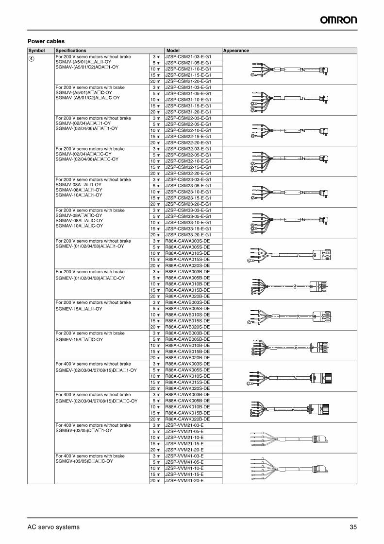
Power cables
Symbol Specifications Model Appearance
D For 200 V servo motors without brakeSGMJV-(A5/01)A@A@1-OYSGMAV-(A5/01/C2)ADA@1-OY
3 m JZSP-CSM21-03-E-G15 m JZSP-CSM21-05-E-G1
10 m JZSP-CSM21-10-E-G115 m JZSP-CSM21-15-E-G120 m JZSP-CSM21-20-E-G1
For 200 V servo motors with brakeSGMJV-(A5/01)A@A@C-OYSGMAV-(A5/01/C2)A@A@C-OY
3 m JZSP-CSM31-03-E-G15 m JZSP-CSM31-05-E-G1
10 m JZSP-CSM31-10-E-G115 m JZSP-CSM31-15-E-G120 m JZSP-CSM31-20-E-G1
For 200 V servo motors without brakeSGMJV-(02/04)A@A@1-OYSGMAV-(02/04/06)A@A@1-OY
3 m JZSP-CSM22-03-E-G15 m JZSP-CSM22-05-E-G1
10 m JZSP-CSM22-10-E-G115 m JZSP-CSM22-15-E-G120 m JZSP-CSM22-20-E-G1
For 200 V servo motors with brakeSGMJV-(02/04)A@A@C-OYSGMAV-(02/04/06)A@A@C-OY
3 m JZSP-CSM32-03-E-G15 m JZSP-CSM32-05-E-G1
10 m JZSP-CSM32-10-E-G115 m JZSP-CSM32-15-E-G120 m JZSP-CSM32-20-E-G1
For 200 V servo motors without brakeSGMJV-08A@A@1-OYSGMAV-08A@A@1-OYSGMAV-10A@A@1-OY
3 m JZSP-CSM23-03-E-G15 m JZSP-CSM23-05-E-G1
10 m JZSP-CSM23-10-E-G115 m JZSP-CSM23-15-E-G120 m JZSP-CSM23-20-E-G1
For 200 V servo motors with brakeSGMJV-08A@A@C-OYSGMAV-08A@A@C-OYSGMAV-10A@A@C-OY
3 m JZSP-CSM33-03-E-G15 m JZSP-CSM33-05-E-G1
10 m JZSP-CSM33-10-E-G115 m JZSP-CSM33-15-E-G120 m JZSP-CSM33-20-E-G1
For 200 V servo motors without brakeSGMEV-(01/02/04/08)A@A@1-OY
3 m R88A-CAWA003S-DE5 m R88A-CAWA005S-DE
10 m R88A-CAWA010S-DE15 m R88A-CAWA015S-DE20 m R88A-CAWA020S-DE
For 200 V servo motors with brakeSGMEV-(01/02/04/08)A@A@C-OY
3 m R88A-CAWA003B-DE5 m R88A-CAWA005B-DE
10 m R88A-CAWA010B-DE15 m R88A-CAWA015B-DE20 m R88A-CAWA020B-DE
For 200 V servo motors without brakeSGMEV-15A@A@1-OY
3 m R88A-CAWB003S-DE5 m R88A-CAWB005S-DE
10 m R88A-CAWB010S-DE15 m R88A-CAWB015S-DE20 m R88A-CAWB020S-DE
For 200 V servo motors with brakeSGMEV-15A@A@C-OY
3 m R88A-CAWB003B-DE5 m R88A-CAWB005B-DE
10 m R88A-CAWB010B-DE15 m R88A-CAWB015B-DE20 m R88A-CAWB020B-DE
For 400 V servo motors without brakeSGMEV-(02/03/04/07/08/15)D@A@1-OY
3 m R88A-CAWK003S-DE5 m R88A-CAWK005S-DE
10 m R88A-CAWK010S-DE15 m R88A-CAWK015S-DE20 m R88A-CAWK020S-DE
For 400 V servo motors without brakeSGMEV-(02/03/04/07/08/15)D@A@C-OY
3 m R88A-CAWK003B-DE5 m R88A-CAWK005B-DE
10 m R88A-CAWK010B-DE15 m R88A-CAWK015B-DE20 m R88A-CAWK020B-DE
For 400 V servo motors without brakeSGMGV-(03/05)D@A@1-OY
3 m JZSP-VVM21-03-E5 m JZSP-VVM21-05-E
10 m JZSP-VVM21-10-E15 m JZSP-VVM21-15-E20 m JZSP-VVM21-20-E
For 400 V servo motors with brakeSGMGV-(03/05)D@A@C-OY
3 m JZSP-VVM41-03-E5 m JZSP-VVM41-05-E
10 m JZSP-VVM41-10-E15 m JZSP-VVM41-15-E20 m JZSP-VVM41-20-E
35AC servo systems
Sigma-5 servo system 29
AC
Ser
vo s
yste
ms
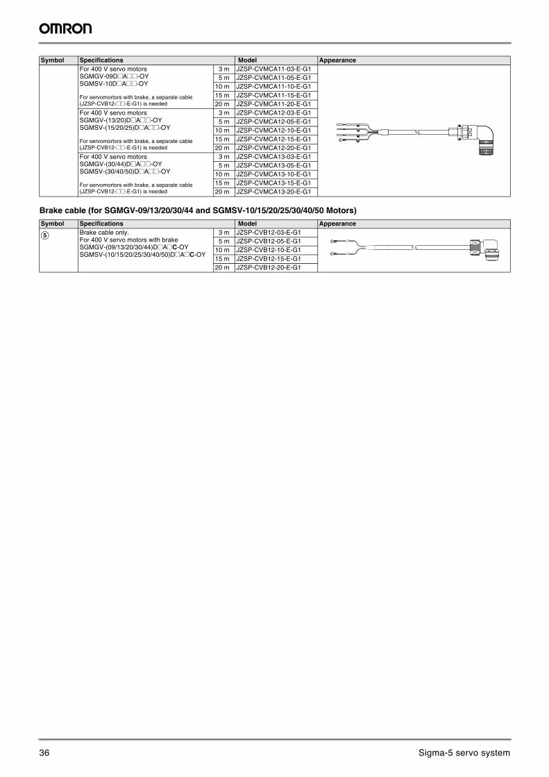
Brake cable (for SGMGV-09/13/20/30/44 and SGMSV-10/15/20/25/30/40/50 Motors)
For 400 V servo motorsSGMGV-09D@A@@-OYSGMSV-10D@A@@-OY
For servomortors with brake, a separate cable (JZSP-CVB12-@@-E-G1) is needed
3 m JZSP-CVMCA11-03-E-G15 m JZSP-CVMCA11-05-E-G1
10 m JZSP-CVMCA11-10-E-G115 m JZSP-CVMCA11-15-E-G120 m JZSP-CVMCA11-20-E-G1
For 400 V servo motorsSGMGV-(13/20)D@A@@-OYSGMSV-(15/20/25)D@A@@-OY
For servomortors with brake, a separate cable (JZSP-CVB12-@@-E-G1) is needed
3 m JZSP-CVMCA12-03-E-G15 m JZSP-CVMCA12-05-E-G1
10 m JZSP-CVMCA12-10-E-G115 m JZSP-CVMCA12-15-E-G120 m JZSP-CVMCA12-20-E-G1
For 400 V servo motorsSGMGV-(30/44)D@A@@-OYSGMSV-(30/40/50)D@A@@-OY
For servomortors with brake, a separate cable (JZSP-CVB12-@@-E-G1) is needed
3 m JZSP-CVMCA13-03-E-G15 m JZSP-CVMCA13-05-E-G1
10 m JZSP-CVMCA13-10-E-G115 m JZSP-CVMCA13-15-E-G120 m JZSP-CVMCA13-20-E-G1
Symbol Specifications Model Appearance
E Brake cable only. For 400 V servo motors with brakeSGMGV-(09/13/20/30/44)D@A@C-OYSGMSV-(10/15/20/25/30/40/50)D@A@C-OY
3 m JZSP-CVB12-03-E-G15 m JZSP-CVB12-05-E-G1
10 m JZSP-CVB12-10-E-G115 m JZSP-CVB12-15-E-G120 m JZSP-CVB12-20-E-G1
Symbol Specifications Model Appearance
36 Sigma-5 servo system
30 AC servo systems
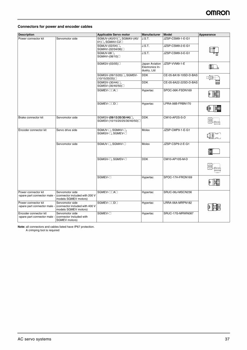
Connectors for power and encoder cables
Note: all connectors and cables listed have IP67 protection. A crimping tool is required
Description Applicable Servo motor Manufacturer Model AppearancePower connector kit Servomotor side SGMJV-(A5/01)@, SGMAV-(A5/
01)@, [email protected]. JZSP-CSM9-1-E-G1
SGMJV-(02/04)@, SGMAV-(02/04/06)@
J.S.T. JZSP-CSM9-2-E-G1
SGMJV-08@,SGMAV-(08/10)@
J.S.T. JZSP-CSM9-3-E-G1
SGMGV-(03/05)@ Japan Aviation Electronics In-dustry, Ltd
JZSP-VVM9-1-E
SGMGV-(09/13/20)@, SGMSV-(10/15/20/25)@
DDK CE-05-8A18-10SD-D-BAS
SGMGV-(30/44)@,SGMSV-(30/40/50)@
DDK CE-05-8A22-22SD-D-BAS
SGMEV-@@A@ Hypertac SPOC-06K-FSDN169
SGMEV-@@D@ Hypertac LPRA-06B-FRBN170
Brake connector kit Servomotor side SGMGV-(09/13/20/30/44)@, SGMSV-(10/15/20/25/30/40/50)@
DDK CM10-AP2S-S-D
Encoder connector kit Servo drive side SGMJV-@, SGMAV-@,SGMGV-@, SGMEV-@
Molex JZSP-CMP9-1-E-G1
Servomotor side SGMJV-@, SGMAV-@ Molex JZSP-CSP9-2-E-G1
SGMGV-@, SGMSV-@ DDK CM10-AP10S-M-D
SGMEV-@ Hypertac SPOC-17H-FRON169
Power connector kit -spare part connector male -
Servomotor side(connector included with 200 V models SGMEV motors)
SGMEV-@@A@ Hypertac SRUC-06J-MSCN236
Power connector kit -spare part connector male -
Servomotor side(connector included with 400 V models SGMEV motors)
SGMEV-@@D@ Hypertac LRRA-06A-MRPN182
Encoder connector kit-spare part connector male -
Servomotor side(connector included with SGMEV motors)
SGMEV-@ Hypertac SRUC-17G-MRWN087
37AC servo systems
Sigma-5 servo system 31
AC
Ser
vo s
yste
ms
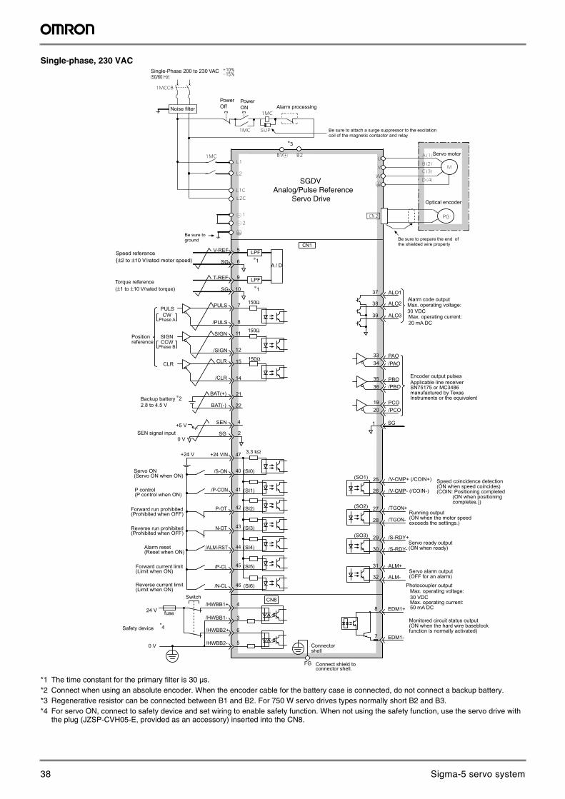
Single-phase, 230 VAC
*1 The time constant for the primary filter is 30 µs.*2 Connect when using an absolute encoder. When the encoder cable for the battery case is connected, do not connect a backup battery.*3 Regenerative resistor can be connected between B1 and B2. For 750 W servo drives types normally short B2 and B3.*4 For servo ON, connect to safety device and set wiring to enable safety function. When not using the safety function, use the servo drive with
the plug (JZSP-CVH05-E, provided as an accessory) inserted into the CN8.
10
V-REF
SGA / D
5
6
LPF
T-REF
SG
9 LPF
2+5 V
0 V
SEN
SG
BAT(+)
BAT(-)
ALO1
ALO2
ALO3
PBO
PCO
/PBO
PAO/PAO
/PCO
/V-CMP+ (/COIN+)
/V-CMP- (/COIN-)
/TGON+
/TGON-
/S-RDY+
ALM+
ALM-
4
22
14
15
21
27
28
29
30
31
32
(SO1)(SI0)
(SI1)
(SI2)
(SI3)
(SI4)
(SI5)
(SI6)
(SO2)
(SO3)
26
25
19
3334
3536
20
37
38
39
+24 V +24 VIN 3.3 kΩ
/S-ON
/P-CON
P-OT
N-OT
/ALM-RST
/N-CL
47
41
43
42
44
45/P-CL
46
40
/S-RDY-
∗3
150Ω
PULS
SIGN
CLR CLR
/CLR
1 SG
Alarm code outputMax. operating voltage:30 VDCMax. operating current:20 mA DC
Encoder output pulsesApplicable line receiverSN75175 or MC3486manufactured by Texas Instruments or the equivalent
Servo ON(Servo ON when ON)
Reverse run prohibited(Prohibited when OFF)
Forward run prohibited(Prohibited when OFF)
Alarm reset(Reset when ON)
Reverse current limit(Limit when ON)
Forward current limit(Limit when ON)
SEN signal input
Backup battery2.8 to 4.5 V
∗2
P control(P control when ON)
Speed coincidence detection (ON when speed coincides)(COIN: Positioning completed (ON when positioning completes.))
Running output(ON when the motor speedexceeds the settings.)
Servo ready output(ON when ready)
Servo alarm output(OFF for an alarm)
Photocoupler outputMax. operating voltage:30 VDCMax. operating current: 50 mA DC
Positionreference
CWPhase A
CCWPhase B
7
8
12
11
/PULS
SIGN
/SIGN
PULS
150Ω
150Ω
EDM1+
EDM1-
FG Connect shield to connector shell.
/HWBB1+
/HWBB1-
/HWBB2+
/HWBB2-
Switch
fuse24 V
0 V
Safety device
CN8
6
3
4
5
8
7
Speed reference(±2 to ±10 V/rated motor speed)
Torque reference(±1 to ±10 V/rated torque)
Be sure toground Be sure to prepare the end of
the shielded wire properly
Optical encoder
Servo motor
Be sure to attach a surge suppressor to the excitationcoil of the magnetic contactor and relay
Alarm processingPowerOff
PowerONNoise filter
Single-Phase 200 to 230 VAC
SGDVAnalog/Pulse Reference Servo Drive
Monitored circuit status output(ON when the hard wire baseblock function is normally activated)
Connectorshell
∗1
∗1
*4
CN1
38 Sigma-5 servo system
32 AC servo systems
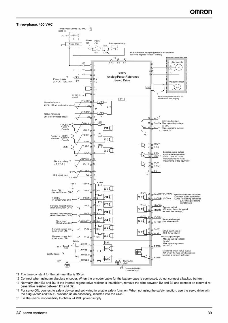
Three-phase, 400 VAC
*1 The time constant for the primary filter is 30 µs.*2 Connect when using an absolute encoder. When the encoder cable for the battery case is connected, do not connect a backup battery.*3 Normally short B2 and B3. If the internal regenerative resistor is insufficient, remove the wire between B2 and B3 and connect an external re-
generative resistor between B1 and B2.*4 For servo ON, connect to safety device and set wiring to enable safety function. When not using the safety function, use the servo drive with
the plug (JZSP-CVH05-E, provided as an accessory) inserted into the CN8.*5 It is the user’s responsibility to obtain 24 VDC power supply.
10
V-REF
SGA / D
5
6
LPF
T-REF
SG
9 LPF
2+5 V
0 V
SEN
SG
BAT(+)
BAT(-)
ALO1
ALO2
ALO3
PBO
PCO
/PBO
PAO/PAO
/PCO
/V-CMP+ (/COIN+)
/V-CMP- (/COIN-)
/TGON+
/TGON-
/S-RDY+
ALM+
ALM-
4
22
14
15
21
27
28
29
30
31
32
(SO1)(SI0)
(SI1)
(SI2)
(SI3)
(SI4)
(SI5)
(SI6)
(SO2)
(SO3)
26
25
19
3334
3536
20
37
38
39
+24 V +24 VIN 3.3 kΩ
/S-ON
/P-CON
P-OT
N-OT
/ALM-RST
/N-CL
47
41
43
42
44
45/P-CL
46
40
/S-RDY-
∗3
150Ω
PULS
SIGN
CLR CLR
/CLR
1 SG
Alarm code outputMax. operating voltage:30 VDCMax. operating current:20 mA DC
Encoder output pulsesApplicable line receiverSN75175 or MC3486manufactured by Texas Instruments or the equivalent
Servo ON(Servo ON when ON)
Reverse run prohibited(Prohibited when OFF)
Forward run prohibited(Prohibited when OFF)
Alarm reset(Reset when ON)
Reverse current limit(Limit when ON)
Forward current limit(Limit when ON)
SEN signal input
Backup battery2.8 to 4.5 V
∗2
P control(P control when ON)
Speed coincidence detection (ON when speed coincides)(COIN: Positioning completed (ON when positioning completes.))
Running output(ON when the motor speedexceeds the settings.)
Servo ready output(ON when ready)
Servo alarm output(OFF for an alarm)
Photocoupler outputMax. operating voltage:30 VDCMax. operating current: 50 mA DC
Positionreference
CWPhase A
CCWPhase B
7
8
12
11
/PULS
SIGN
/SIGN
PULS
150Ω
150Ω
EDM1+
EDM1-
FG Connect shield to connector shell.
/HWBB1+
/HWBB1-
/HWBB2+
/HWBB2-
Switch
fuse24 V
0 V
Safety device
CN8
6
3
4
5
8
7
Speed reference(±2 to ±10 V/rated motor speed)
Torque reference(±1 to ±10 V/rated torque)
Be sure toground Be sure to prepare the end of
the shielded wire properly
Optical encoder
Servo motor
Be sure to attach a surge suppressor to the excitationcoil of the magnetic contactor and relay
Alarm processingPowerOff
PowerONNoise filter
Three-Phase 380 to 480 VAC
Monitored circuit status output(ON when the hard wire baseblock function is normally activated)
Connectorshell
∗1
∗1
*4
3
Power supply 24 VDC +10%,-15%
+24 V
0 V
3
24 V
0 V
∗5
CN1
SGDVAnalog/Pulse Reference Servo Drive
39AC servo systems
Sigma-5 servo system 33
AC
Ser
vo s
yste
ms
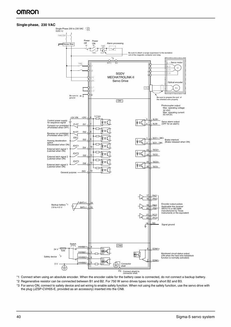
Single-phase, 230 VAC
*1 Connect when using an absolute encoder. When the encoder cable for the battery case is connected, do not connect a backup battery.*2 Regenerative resistor can be connected between B1 and B2. For 750 W servo drives types normally short B2 and B3.*3 For servo ON, connect to safety device and set wiring to enable safety function. When not using the safety function, use the servo drive with
the plug (JZSP-CVH05-E, provided as an accessory) inserted into the CN8.
ALM+
ALM-
SO1+ / BK+
SO1- / BK-
/SO2+
/SO2-
/SO3+
23
24
25
26
2
1
3
4
/SO3-
∗2
BAT(+)
BAT(-) 15
14Backup battery2.8 to 4.5 V
∗1
Brake interlock(Brake released when ON)
Servo alarm output(OFF for an alarm)
Photocoupler outputMax. operating voltage:30 VDCMax. operating current: 50 mA DC
CN1
+24 VIN +24V 3.3 kΩ
/SI1
/SI2
/SI3
/SI4
/SI5
/SIO
6
8
10
9
11
12/SI6
13
7
Control power supplyfor sequence signal
Reverse run prohibited(Prohibited when OFF)
Forward run prohibited(Prohibited when OFF)
External latch signal 1(Latched when ON)
Homing decelerationswitch(Decelerated when ON)
EDM1+
EDM1-
FG Connect shield to connector shell.
/HWBB1+
/HWBB1-
/HWBB2+
/HWBB2-
Switch
fuse24 V
0 V
Safety device
CN8
6
3
4
5
8
7
Be sure toground Be sure to prepare the end of
the shielded wire properly
Optical encoder
Servo motor
Be sure to attach a surge suppressor to the excitationcoil of the magnetic contactor and relay
Alarm processingPowerOff
PowerONNoise filter
Single-Phase 200 to 230 VAC
SGDVMECHATROLINK-II Servo Drive
Monitored circuit status output(ON when the hard wire baseblock function is normally activated)
Connectorshell
*3
PBO
PCO
/PBO
PAO/PAO
/PCO21
1718
1920
22
16 SG
Encoder output pulsesApplicable line receiverSN75175 or MC3486manufactured by Texas Instruments or the equivalent
Signal ground
P-OT
N-OT
/DEC
/EXT1
/EXT2
/EXT3
External latch signal 2(Latched when ON)
External latch signal 3(Latched when ON)
General purpose
40 Sigma-5 servo system
34 AC servo systems
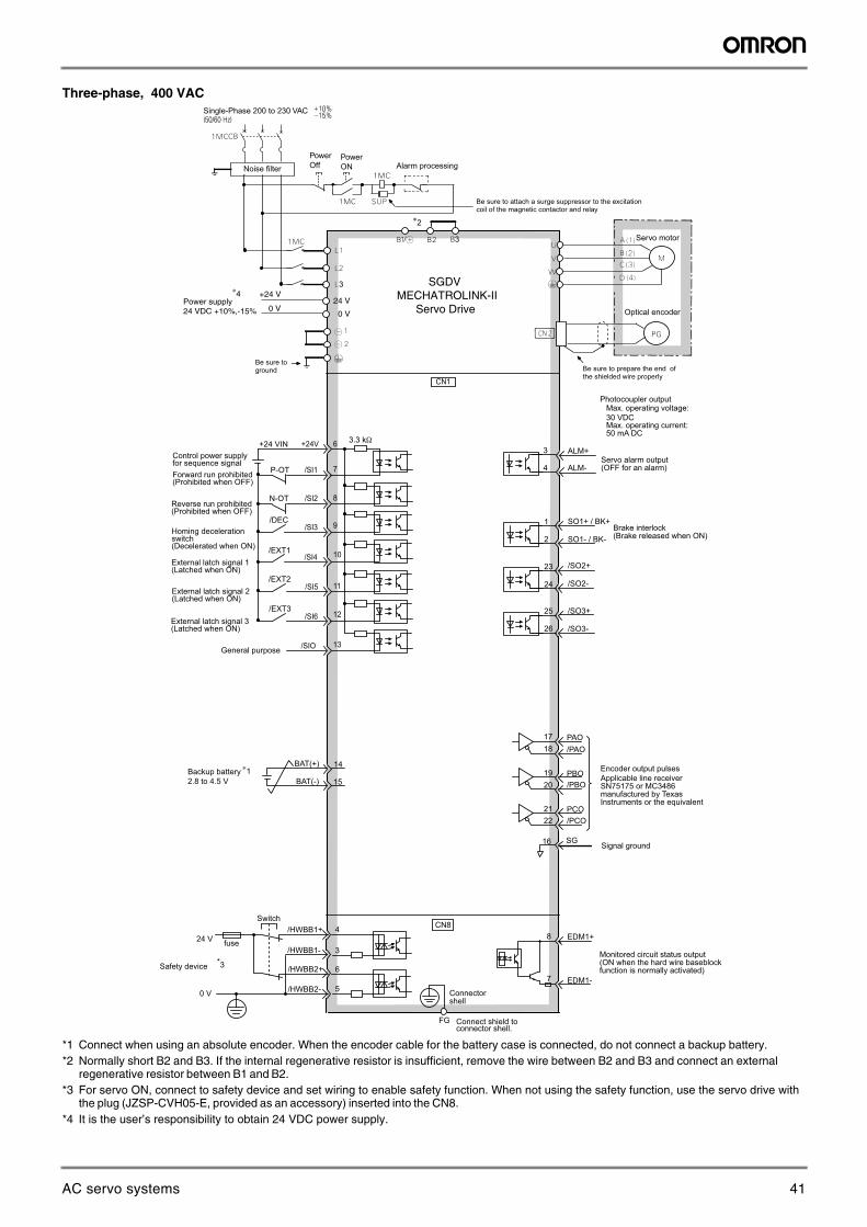
Three-phase, 400 VAC
*1 Connect when using an absolute encoder. When the encoder cable for the battery case is connected, do not connect a backup battery. *2 Normally short B2 and B3. If the internal regenerative resistor is insufficient, remove the wire between B2 and B3 and connect an external
regenerative resistor between B1 and B2. *3 For servo ON, connect to safety device and set wiring to enable safety function. When not using the safety function, use the servo drive with
the plug (JZSP-CVH05-E, provided as an accessory) inserted into the CN8. *4 It is the user’s responsibility to obtain 24 VDC power supply.
ALM+
ALM-
SO1+ / BK+
SO1- / BK-
/SO2+
/SO2-
/SO3+
23
24
25
26
2
1
3
4
/SO3-
∗2
BAT(+)
BAT(-) 15
14Backup battery2.8 to 4.5 V
∗1
Brake interlock(Brake released when ON)
Servo alarm output(OFF for an alarm)
Photocoupler outputMax. operating voltage:30 VDCMax. operating current: 50 mA DC
CN1
+24 VIN +24V 3.3 kΩ
/SI1
/SI2
/SI3
/SI4
/SI5
/SIO
6
8
10
9
11
12/SI6
13
7
Control power supplyfor sequence signal
Reverse run prohibited(Prohibited when OFF)
Forward run prohibited(Prohibited when OFF)
External latch signal 1(Latched when ON)
Homing decelerationswitch(Decelerated when ON)
EDM1+
EDM1-
FG Connect shield to connector shell.
/HWBB1+
/HWBB1-
/HWBB2+
/HWBB2-
Switch
fuse24 V
0 V
Safety device
CN8
6
3
4
5
8
7
Be sure toground Be sure to prepare the end of
the shielded wire properly
Optical encoder
Servo motor
Be sure to attach a surge suppressor to the excitationcoil of the magnetic contactor and relay
Alarm processingPowerOff
PowerONNoise filter
Single-Phase 200 to 230 VAC
Monitored circuit status output(ON when the hard wire baseblock function is normally activated)
Connectorshell
*3
PBO
PCO
/PBO
PAO/PAO
/PCO21
1718
1920
22
16 SG
Encoder output pulsesApplicable line receiverSN75175 or MC3486manufactured by Texas Instruments or the equivalent
Signal ground
P-OT
N-OT
/DEC
/EXT1
/EXT2
/EXT3
External latch signal 2(Latched when ON)
External latch signal 3(Latched when ON)
General purpose
3
3
Power supply 24 VDC +10%,-15%
+24 V
0 V24 V
0 V
∗4 SGDVMECHATROLINK-II Servo Drive
41AC servo systems
Sigma-5 servo system 35
AC
Ser
vo s
yste
ms
Ordering information
Sigma-5 Analog/Pulse Reference Configuration
Note: The symbols ABCDE... show the recommended sequence to select the components in a Sigma-5 servo system
Servo motors, power & encoder cablesNote: AB Refer to the servo motors chapter for detailed motor specifications and selection
Position control unit
Terminal block position control
General purpose cable
Battery case for absolute encoder
Analog monitor cable
USB cable
Safety cable
CablesCables
SGMGH, SGMUH, SGMSH, SGMBH Servo Motor
(Refer to chapter Sigma linear motors)
SGMAH, SGMPHServo Motor
SGLT_ linearServo Motor
SGLG_ linearServo Motor
SGLF_ linear Servo Motor
(Refer to chapter Sigma-II rotary motors)
Cables
SGMGV, SGMSV Servo Motor
SGMJV, SGMAVServo Motor
(Refer to chapter Sigma-5 rotary motors)
Direct drive servo motor
Direct drive servo motor
Cables(Refer to chapter Sigma direct drive motors)
Sigma-5 Servo Drives
Analog/Pulse Models
C
D
J
I
E
G
L
M F
H
Filter
A A
A A
A A A
A A
B B
B B
K
Personalcomputer
42 Sigma-5 servo system
36 AC servo systems
Servo drives
Symbol Specifications Model Compatible rotary servo motors A Compatible direct drive motors A Compatible linear motors A
C 1 phase 230 VAC
50 W SGDV-A5A01A-OY SGMAH-A5D@, SGMJV-A5A@, SGMAV-A5A@
- -
SGDV-A5A05A-OY - - SGLGW-30A050@100 W SGDV-01A01A-OY SGMAH-01A@, SGMPH-01A@,
SGMJV-01A@, SGMAV-01A@, SGMEV-01A@
- -
SGDV-01A05A-OY - - SGLGW-30A080@, SGLGW-40A140@
200 W SGDV-02A01A-OY SGMAH-02A@, SGMPH-02A@, SGMJV-02A@, SGMAV-02A@,SGMEV-02A@
SGMCS-07B@ -
SGDV-02A05A-OY - - SGLGW-60A140@,SGLGW-40A253@,SGLFW-20A@, SGLFW-35A120@
400 W SGDV-04A01A-OY SGMAH-04A@, SGMPH-04A@,SGMJV-04A@, SGMAV-04A@,SGMEV-04A@
SGMCS-02B@, SGMCS-05B@,SGMCS-04C@, SGMCS-10C@,SGMCS-14C@, SGMCS-08D@,SGMCS-17D@, SGMCS-25D@
-
SGDV-04A05A-OY - - SGLGW-40A365@, SGLGW-60A253A@
750 W SGDV-08A01A-OY SGMAH-08A@, SGMPH-08A@,SGMJV-08A@, SGMAV-08A@,SGMEV-08A@
SGMCS-16E@, SGMCS-35E@ -
SGDV-08A05A-OY - - SGLGW-60A365A@, SGLFW-35A230@,SGLFW-50A200@
1.5 kW SGDV-15A01A-OY SGMPH-15A@, SGMAV-10A@, SGMEV-15A@
SGMCS-45M@, SGMCS-80M@,SGMCS-80N@
-
SGDV-15A05A-OY - - SGLGW-90A200A@, SGLFW-50A380@,SGLFW-1ZA200@
3 phase 400 VAC
0.5 kW SGDV-05D01A-OY SGMAH-03D@, SGMPH-04D@, SGMGH-05D@, SGMEV-04D@, SGMGV-05D@
- -
SGDV-05D05A-OY - - [email protected] kW SGDV-10D01A-OY SGMAH-07D@, SGMPH-08D@,
SGMGH-09D@, SGMSH-10D@, SGMUH-10D@, SGMEV-08D@, SGMGV-09D@, SGMSV-10D@,
- -
SGDV-10D05A-OY - - SGLFW-50D200@,SGLTW-35D170@,SGLTW-50D170@
1.5 kW SGDV-15D01A-OY SGMPH-15D@, SGMGH-13D@, SGMSH-15D@, SGMUH-15D@, SGMEV-15D@, SGMGV-13D@,SGMSV-15D@
- -
SGDV-15D05A-OY - - SGLFW-50D380@, SGLFW-1ZD200@
2 kW SGDV-20D01A-OY SGMGH-20D@, SGMSH-20D@,SGMGV-20D@, SGMSV-20D@
- -
SGDV-20D05A-OY - - SGLFW-1ED380@,SGLTW-35D320@,SGLTW-50D320@
3 kW SGDV-30D01A-OY SGMGH-30D@, SGMSH-30D@, SGMUH-30D@, SGMGV-30D@, SGMGV-30D@
-
-
SGDV-30D05A-OY - - SGLFW-1ZD380@,SGLFW-1ED560@,SGLTW-40D400@
5 kW SGDV-50D01A-OY SGMGH-44D@, SGMSH-50D@, SGMUH-40D@, SGMGV-44D@,SGMSV-50D@
- -
SGDV-50D05A-OY - - SGLTW-40D60@,SGLTW-80D400@
43AC servo systems
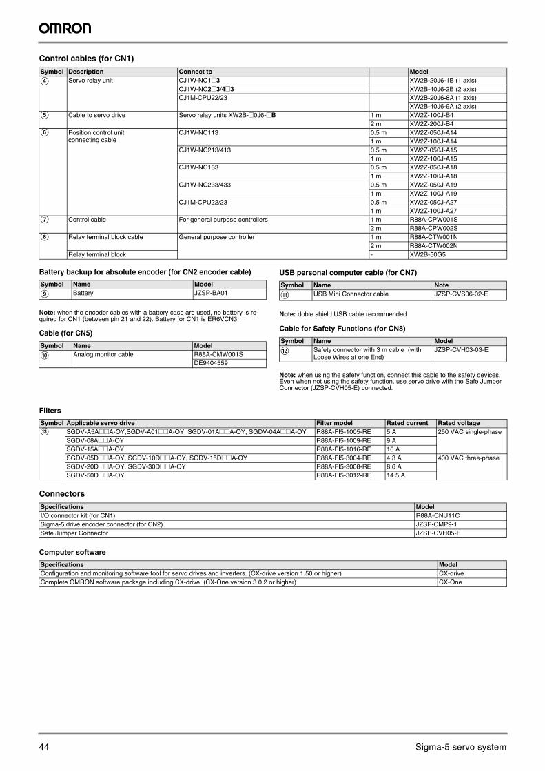
Sigma-5 servo system 37
AC
Ser
vo s
yste
ms
Control cables (for CN1)
Battery backup for absolute encoder (for CN2 encoder cable)
Note: when the encoder cables with a battery case are used, no battery is re-quired for CN1 (between pin 21 and 22). Battery for CN1 is ER6VCN3.
Cable (for CN5)
USB personal computer cable (for CN7)
Note: doble shield USB cable recommended
Cable for Safety Functions (for CN8)
Note: when using the safety function, connect this cable to the safety devices. Even when not using the safety function, use servo drive with the Safe Jumper Connector (JZSP-CVH05-E) connected.
Filters
Connectors
Computer software
Symbol Description Connect to Model
D Servo relay unit CJ1W-NC1@3 XW2B-20J6-1B (1 axis)CJ1W-NC2@3/4@3 XW2B-40J6-2B (2 axis)CJ1M-CPU22/23 XW2B-20J6-8A (1 axis)
XW2B-40J6-9A (2 axis)E Cable to servo drive Servo relay units XW2B-@0J6-@B 1 m XW2Z-100J-B4
2 m XW2Z-200J-B4F Position control unit
connecting cableCJ1W-NC113 0.5 m XW2Z-050J-A14
1 m XW2Z-100J-A14CJ1W-NC213/413 0.5 m XW2Z-050J-A15
1 m XW2Z-100J-A15CJ1W-NC133 0.5 m XW2Z-050J-A18
1 m XW2Z-100J-A18CJ1W-NC233/433 0.5 m XW2Z-050J-A19
1 m XW2Z-100J-A19CJ1M-CPU22/23 0.5 m XW2Z-050J-A27
1 m XW2Z-100J-A27G Control cable For general purpose controllers 1 m R88A-CPW001S
2 m R88A-CPW002SH Relay terminal block cable General purpose controller 1 m R88A-CTW001N
2 m R88A-CTW002NRelay terminal block - XW2B-50G5
Symbol Name Model
I Battery JZSP-BA01
Symbol Name Model
J Analog monitor cable R88A-CMW001SDE9404559
Symbol Name Note
K USB Mini Connector cable JZSP-CVS06-02-E
Symbol Name Model
L Safety connector with 3 m cable (with Loose Wires at one End)
JZSP-CVH03-03-E
Symbol Applicable servo drive Filter model Rated current Rated voltageM SGDV-A5A@@A-OY,SGDV-A01@@A-OY, SGDV-01A@@A-OY, SGDV-04A@@A-OY R88A-FI5-1005-RE 5 A 250 VAC single-phase
SGDV-08A@@A-OY R88A-FI5-1009-RE 9 ASGDV-15A@@A-OY R88A-FI5-1016-RE 16 ASGDV-05D@@A-OY, SGDV-10D@@A-OY, SGDV-15D@@A-OY R88A-FI5-3004-RE 4.3 A 400 VAC three-phaseSGDV-20D@@A-OY, SGDV-30D@@A-OY R88A-FI5-3008-RE 8.6 ASGDV-50D@@A-OY R88A-FI5-3012-RE 14.5 A
Specifications ModelI/O connector kit (for CN1) R88A-CNU11CSigma-5 drive encoder connector (for CN2) JZSP-CMP9-1Safe Jumper Connector JZSP-CVH05-E
Specifications ModelConfiguration and monitoring software tool for servo drives and inverters. (CX-drive version 1.50 or higher) CX-driveComplete OMRON software package including CX-drive. (CX-One version 3.0.2 or higher) CX-One
44 Sigma-5 servo system
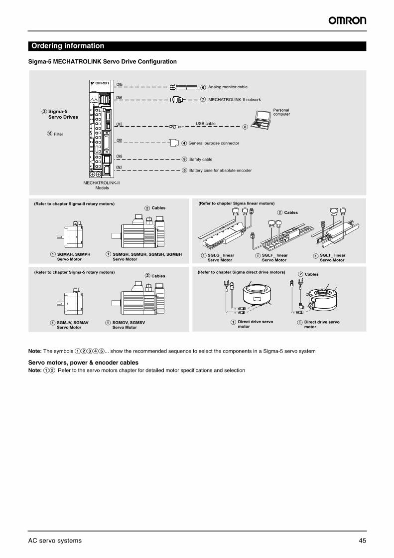
38 AC servo systems
Ordering information
Sigma-5 MECHATROLINK Servo Drive Configuration
Note: The symbols ABCDE... show the recommended sequence to select the components in a Sigma-5 servo system
Servo motors, power & encoder cablesNote: AB Refer to the servo motors chapter for detailed motor specifications and selection
Battery case for absolute encoder
Analog monitor cable
USB cable
Safety cable
CablesCables
SGMGH, SGMUH, SGMSH, SGMBH Servo Motor
(Refer to chapter Sigma linear motors)
SGMAH, SGMPHServo Motor
SGLT_ linearServo Motor
SGLG_ linearServo Motor
SGLF_ linear Servo Motor
(Refer to chapter Sigma-II rotary motors)
Cables
SGMGV, SGMSV Servo Motor
SGMJV, SGMAVServo Motor
(Refer to chapter Sigma-5 rotary motors)
Direct drive servo motor
Direct drive servo motor
Cables(Refer to chapter Sigma direct drive motors)
Sigma-5 Servo Drives
C
D
Filter
A A
A A
A A A
A A
B B
B B
MECHATROLINK-II Models
MECHATROLINK-II network
General purpose connector
E
F
G
H
I
J
Personalcomputer
45AC servo systems
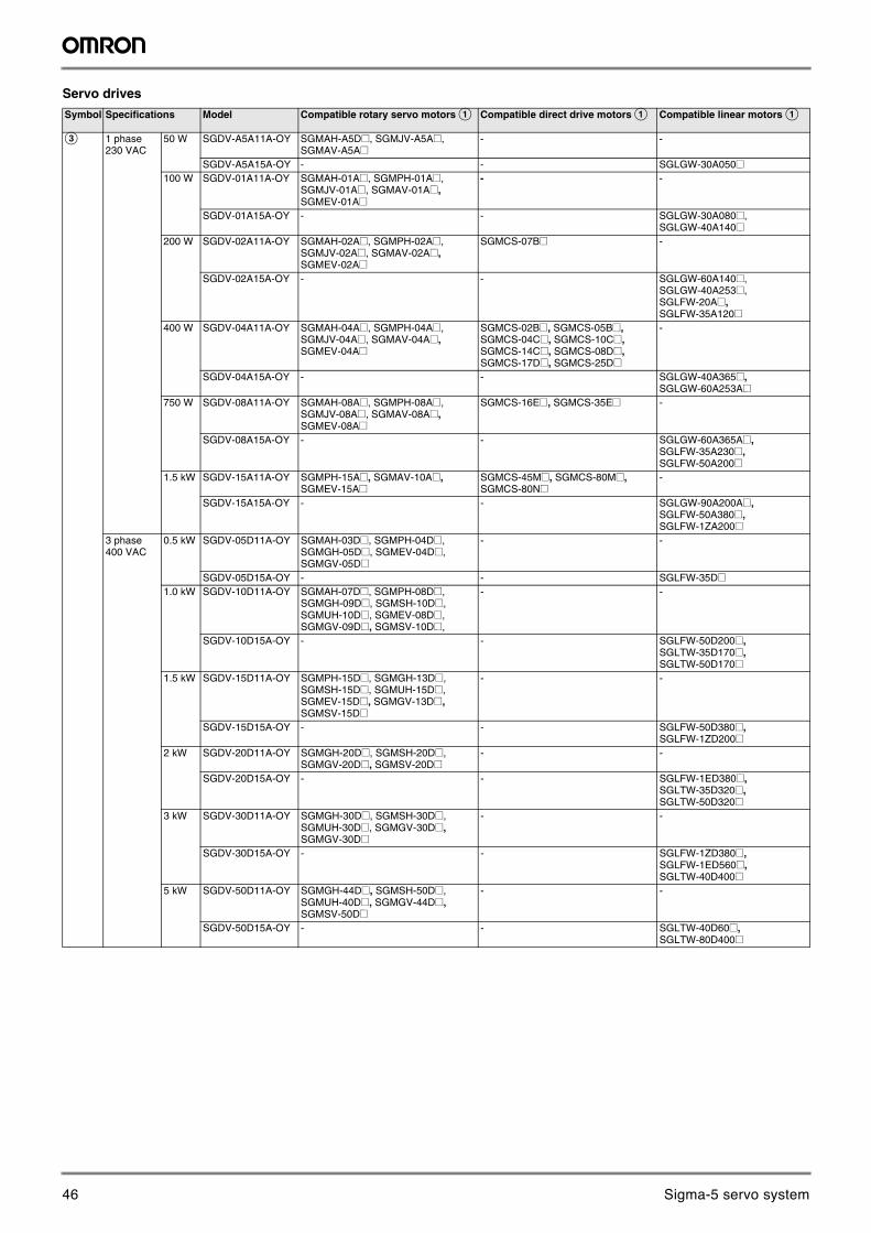
Sigma-5 servo system 39
AC
Ser
vo s
yste
ms
Servo drives
Symbol Specifications Model Compatible rotary servo motors A Compatible direct drive motors A Compatible linear motors A
C 1 phase 230 VAC
50 W SGDV-A5A11A-OY SGMAH-A5D@, SGMJV-A5A@, SGMAV-A5A@
- -
SGDV-A5A15A-OY - - SGLGW-30A050@100 W SGDV-01A11A-OY SGMAH-01A@, SGMPH-01A@,
SGMJV-01A@, SGMAV-01A@, SGMEV-01A@
- -
SGDV-01A15A-OY - - SGLGW-30A080@, SGLGW-40A140@
200 W SGDV-02A11A-OY SGMAH-02A@, SGMPH-02A@, SGMJV-02A@, SGMAV-02A@,SGMEV-02A@
SGMCS-07B@ -
SGDV-02A15A-OY - - SGLGW-60A140@,SGLGW-40A253@,SGLFW-20A@, SGLFW-35A120@
400 W SGDV-04A11A-OY SGMAH-04A@, SGMPH-04A@,SGMJV-04A@, SGMAV-04A@,SGMEV-04A@
SGMCS-02B@, SGMCS-05B@,SGMCS-04C@, SGMCS-10C@,SGMCS-14C@, SGMCS-08D@,SGMCS-17D@, SGMCS-25D@
-
SGDV-04A15A-OY - - SGLGW-40A365@, SGLGW-60A253A@
750 W SGDV-08A11A-OY SGMAH-08A@, SGMPH-08A@,SGMJV-08A@, SGMAV-08A@,SGMEV-08A@
SGMCS-16E@, SGMCS-35E@ -
SGDV-08A15A-OY - - SGLGW-60A365A@, SGLFW-35A230@,SGLFW-50A200@
1.5 kW SGDV-15A11A-OY SGMPH-15A@, SGMAV-10A@, SGMEV-15A@
SGMCS-45M@, SGMCS-80M@,SGMCS-80N@
-
SGDV-15A15A-OY - - SGLGW-90A200A@, SGLFW-50A380@,SGLFW-1ZA200@
3 phase 400 VAC
0.5 kW SGDV-05D11A-OY SGMAH-03D@, SGMPH-04D@, SGMGH-05D@, SGMEV-04D@, SGMGV-05D@
- -
SGDV-05D15A-OY - - [email protected] kW SGDV-10D11A-OY SGMAH-07D@, SGMPH-08D@,
SGMGH-09D@, SGMSH-10D@, SGMUH-10D@, SGMEV-08D@, SGMGV-09D@, SGMSV-10D@,
- -
SGDV-10D15A-OY - - SGLFW-50D200@,SGLTW-35D170@,SGLTW-50D170@
1.5 kW SGDV-15D11A-OY SGMPH-15D@, SGMGH-13D@, SGMSH-15D@, SGMUH-15D@, SGMEV-15D@, SGMGV-13D@,SGMSV-15D@
- -
SGDV-15D15A-OY - - SGLFW-50D380@, SGLFW-1ZD200@
2 kW SGDV-20D11A-OY SGMGH-20D@, SGMSH-20D@,SGMGV-20D@, SGMSV-20D@
- -
SGDV-20D15A-OY - - SGLFW-1ED380@,SGLTW-35D320@,SGLTW-50D320@
3 kW SGDV-30D11A-OY SGMGH-30D@, SGMSH-30D@, SGMUH-30D@, SGMGV-30D@, SGMGV-30D@
-
-
SGDV-30D15A-OY - - SGLFW-1ZD380@,SGLFW-1ED560@,SGLTW-40D400@
5 kW SGDV-50D11A-OY SGMGH-44D@, SGMSH-50D@, SGMUH-40D@, SGMGV-44D@,SGMSV-50D@
- -
SGDV-50D15A-OY - - SGLTW-40D60@,SGLTW-80D400@
46 Sigma-5 servo system
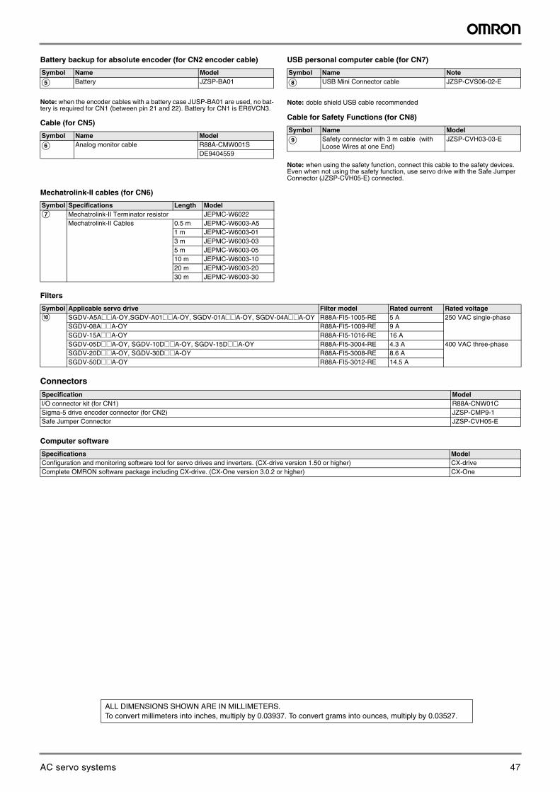
40 AC servo systems
Battery backup for absolute encoder (for CN2 encoder cable)
Note: when the encoder cables with a battery case JUSP-BA01 are used, no bat-tery is required for CN1 (between pin 21 and 22). Battery for CN1 is ER6VCN3.
Cable (for CN5)
USB personal computer cable (for CN7)
Note: doble shield USB cable recommended
Cable for Safety Functions (for CN8)
Note: when using the safety function, connect this cable to the safety devices. Even when not using the safety function, use servo drive with the Safe Jumper Connector (JZSP-CVH05-E) connected.
Mechatrolink-II cables (for CN6)
Filters
Connectors
Computer software
Symbol Name Model
E Battery JZSP-BA01
Symbol Name Model
F Analog monitor cable R88A-CMW001SDE9404559
Symbol Name Note
H USB Mini Connector cable JZSP-CVS06-02-E
Symbol Name Model
I Safety connector with 3 m cable (with Loose Wires at one End)
JZSP-CVH03-03-E
Symbol Specifications Length ModelG Mechatrolink-II Terminator resistor JEPMC-W6022
Mechatrolink-II Cables 0.5 m JEPMC-W6003-A51 m JEPMC-W6003-013 m JEPMC-W6003-035 m JEPMC-W6003-0510 m JEPMC-W6003-1020 m JEPMC-W6003-2030 m JEPMC-W6003-30
Symbol Applicable servo drive Filter model Rated current Rated voltageJ SGDV-A5A@@A-OY,SGDV-A01@@A-OY, SGDV-01A@@A-OY, SGDV-04A@@A-OY R88A-FI5-1005-RE 5 A 250 VAC single-phase
SGDV-08A@@A-OY R88A-FI5-1009-RE 9 ASGDV-15A@@A-OY R88A-FI5-1016-RE 16 ASGDV-05D@@A-OY, SGDV-10D@@A-OY, SGDV-15D@@A-OY R88A-FI5-3004-RE 4.3 A 400 VAC three-phaseSGDV-20D@@A-OY, SGDV-30D@@A-OY R88A-FI5-3008-RE 8.6 ASGDV-50D@@A-OY R88A-FI5-3012-RE 14.5 A
Specification ModelI/O connector kit (for CN1) R88A-CNW01CSigma-5 drive encoder connector (for CN2) JZSP-CMP9-1Safe Jumper Connector JZSP-CVH05-E
Specifications ModelConfiguration and monitoring software tool for servo drives and inverters. (CX-drive version 1.50 or higher) CX-driveComplete OMRON software package including CX-drive. (CX-One version 3.0.2 or higher) CX-One
In the interest of product improvement, specifications are subject to change without notice.
ALL DIMENSIONS SHOWN ARE IN MILLIMETERS.To convert millimeters into inches, multiply by 0.03937. To convert grams into ounces, multiply by 0.03527.
47AC servo systems
BRO_Sigma5_EN_INT01
Austria Tel: +43 (0) 2236 377 800 www.industrial.omron.at
Belgium Tel: +32 (0) 2 466 24 80 www.industrial.omron.be
Czech Republic Tel: +420 234 602 602 www.industrial.omron.cz
Denmark Tel: +45 43 44 00 11 www.industrial.omron.dk
Finland Tel: +358 (0) 207 464 200www.industrial.omron.fi
France Tel: +33 (0) 1 56 63 70 00www.industrial.omron.fr
Germany Tel: +49 (0) 2173 680 00 www.industrial.omron.de
Hungary Tel: +36 1 399 30 50 www.industrial.omron.hu
Italy Tel: +39 02 326 81 www.industrial.omron.it
Netherlands Tel: +31 (0) 23 568 11 00 www.industrial.omron.nl
Norway Tel: +47 (0) 22 65 75 00 www.industrial.omron.no
Poland Tel: +48 (0) 22 645 78 60 www.industrial.omron.pl
Portugal Tel: +351 21 942 94 00 www.industrial.omron.pt
Russia Tel: +7 495 648 94 50 www.industrial.omron.ru
South-AfricaTel: +27 (0)11 579 2600 www.industrial.omron.co.za
Spain Tel: +34 913 777 900 www.industrial.omron.es
Sweden Tel: +46 (0) 8 632 35 00 www.industrial.omron.se
Switzerland Tel: +41 (0) 41 748 13 13 www.industrial.omron.ch
Turkey Tel: +90 216 474 00 40 www.industrial.omron.com.tr
United Kingdom Tel: +44 (0) 870 752 08 61 www.industrial.omron.co.uk
More Omron representativeswww.industrial.omron.eu
Control Systems• Programmable logic controllers • Human-machine interfaces • Remote I/O
Motion & Drives • Motion controllers • Servo systems • Inverters
Control Components • Temperature controllers • Power supplies • Timers • Counters • Programmable relays • Digital panel indicators • Electromechanical relays • Monitoring products • Solid-state relays • Limit switches • Pushbutton switches • Low voltage switch gear
Sensing & Safety • Photoelectric sensors • Inductive sensors • Capacitive & pressure sensors • Cable connectors • Displacement & width-measuring sensors • Vision systems • Safety networks • Safety sensors • Safety units/relay units • Safety door/guard lock switches
Authorised Distributor:
Although we strive for perfection, Omron Europe BV and/or its subsidiary and affiliated companies do not warrant or make any representations regarding the correctness or completeness of the information described in this document. We reserve the right to make any changes at any time without prior notice.
OMRON EUROPE B.V. Wegalaan 67-69, NL-2132 JD, Hoofddorp, The Netherlands. Tel: +31 (0) 23 568 13 00 Fax: +31 (0) 23 568 13 88 www.industrial.omron.eu


