30
DSP Control Group, Inc. Mx4 & Mechatrolink Sigma II and III Link to Mx4 Controllers

DSP Control Group, Inc.
Mx4 & MechatrolinkSigma II and III Link to Mx4 Controllers

Mx4 & Mechatrolink
User’s Guide
V1.2
This documentation may not be copied, photocopied, reproduced, translated,modified or reduced to any electronic medium or machine-readable form, inwhole or in part, without the prior written consent of DSP Control Group, Inc.
© Copyright 2000-2004 DSP Control Group, Inc.4445 W 77th StreetMinneapolis, MN 55435Phone: (952) 831-9556FAX: (952) 831-4697
All rights reserved. Printed in the United States.
The authors and those involved in the manual's production have made everyeffort to provide accurate, useful information.
Use of this product in an electro-mechanical system could result in a mechanicalmotion that could cause harm. DSP Control Group, Inc. is not responsible forany accident resulting from misuse of its products.
DSPL, Mx4 and Vx4++ are trademarks of DSP Control Group, Inc.
Other brand names and product names are trademarks of their respective holders.
DSPCG makes no warranty or condition, either expressed or implied, includingbut not limited to any implied warranties of merchantability and fitness for aparticular purpose, regarding the licensed materials.
Mx4 and Mechatrolink i
Contents
1 Introduction ........................................................................................................ 1-1
Mechatrolink System Wiring....................................................... 1-2 Drive Initialization DLL............................................................... 1-3 Mechatrolink Windows Application Program ............................. 1-4
2 Mechatrolink Windows ............................................................................ 2-1
3 Integrating Mechatrolink With Executive........................... 3-1 Converting DLL Functions to RTC........................................................ 3-4 Mechatrolink DLL Functions ............................................................... 3-9 Mechatrolink RTC Functions ............................................................. 3-15
Mechatrolink II & Mx4 1-1
1 Mechatrolink & Mx4Mechatrolink - Mx4 System Description
Mechatrolink II is a digital link between DSP Control Group’s Mx4 motioncontroller and Yaskawa’s Sigma II or III drives. Other than makingcommunication digital and your drives reachable by the Mx4 motion controllerat a high bandwidth, this link offers no advantage.
Other digital links offered by DSP Control Group at high bandwidth are:Firewire (IEEE 1394), DSPNET (a high-speed IEEE 802.3 physical layer) andEthernet.
In this section, we will describe what you must do to convert your familiaranalog motion controller to a digitally linked system. We start withMechatrolink System Wiring, then go on with the Drive Initialization DLL -through which you must execute a few instructions on the Mx4 motioncontroller (which in turn initializes the drives through the link). From that pointon you may use all drives similar to any analog drive.
Finally, you may use a Windows application program that will let you set up,test and run your motion system before programming your application.

Mechatrolink and Mx4
1-2
Mechatrolink System WiringMinimum System Requirement:
i) Mx4 Motion Controller With Mx4-Mech add-on board(ordered through DSPCG or their distributors)
ii) One to 4 Yaskawa motors and Sigma servo-drives withMechatriolink II option (e.g. Sigma III products)
iii) Mechatrolink cables and Network Terminations. (orderedthrough Yaskawa or their distributors)
M x 4 – M e c hA d d - o n B o a
r dMech
Mechatrolink Cable
Mx4 MotionController
Yaskawa Motorsand Sigma Drives
Termination
atrolink System Wiring Diag
ram
Mechatrolinks and Mx4
Mechatrolinks and Mx4 1-3
Drive Initialization DLLDrive Initialization commands, installed with Mx4pro software, enable theSigma drives to accept basic motion control commands (e.g. velocity command).These commands in order of necessity and priority are:
Must Run - before using Sigma drives with the Mx4 motion controller:
MECH_INIT enables the mechatrolink linkDRIVEMAP maps the drive number onto an axisMECH_CONNECT establishes communication between
control and drivesMECH_FEEDBACK enables feedback mechanism on
mechatrolink driveMECH_CLOOP enables closed loop operation on the
dive.MECH_BLOCK blocks/unblocks the above commands to go
through
Note: You must observe the order of execution for theinstructions listed above
Optionally Run - to either disconnect the drives, poll for or, clear a faultcondition.
MECH_DISCONNECT software disconnects the system elementsMECH_ALARM reads the alarm (fault) from the drivesMECH_CLRALARM clear the faults
Further description for each command is available in the Instruction Set sectionof this short manual
Once the “Must Run” commands are executed, to the Mx4 motion controller, aMechareolink drive appears as a common analog drive. Indeed, with the“Optionally Run” commands, unlike an analog drive, you may poll for a drivefault and clear it as needed.

Mechatrolink and Mx4
1-4
Mechatrolink Windows Application ProgramThis Windows application program allows you to setup, test and run yourMechatrolink System before running your application. This test programconsists of software connecting, initializing, checking for fault and statuscondition and, clearing the fault. This software is to be used in conjunction withMx4pro tuning program provided by DSP Control Group. Further Informationon this program is provided in the next chapter.
Mx4pro Mechatrolink Window 2-1
2 Mechatrolink Windows
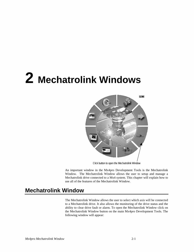
Click button to open the Mechatrolink Window
An important window in the Mx4pro Development Tools is the MechatrolinkWindow. The Mechatrolink Window allows the user to setup and manage aMechatrolink drive connected to a Mx4 system. This chapter will explain how touse all of the features of the Mechatrolink Window.
Mechatrolink WindowThe Mechatrolink Window allows the user to select which axis will be connectedto a Mechatrolink drive. It also allows the monitoring of the drive status and theability to clear drive fault or alarm. To open the Mechatrolink Window click onthe Mechatrolink Window button on the main Mx4pro Development Tools. Thefollowing window will appear:
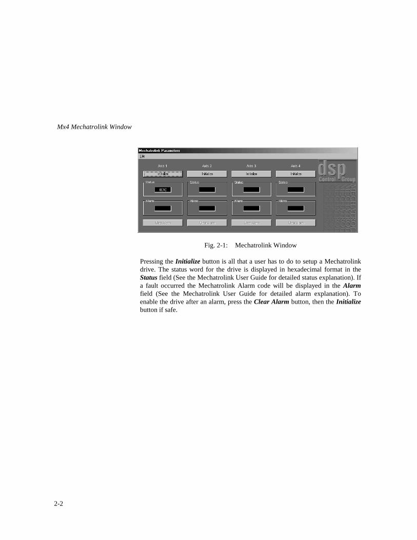
Mx4 Mechatrolink Window
2-2
Fig. 2-1: Mechatrolink Window
Pressing the Initialize button is all that a user has to do to setup a Mechatrolinkdrive. The status word for the drive is displayed in hexadecimal format in theStatus field (See the Mechatrolink User Guide for detailed status explanation). Ifa fault occurred the Mechatrolink Alarm code will be displayed in the Alarmfield (See the Mechatrolink User Guide for detailed alarm explanation). Toenable the drive after an alarm, press the Clear Alarm button, then the Initializebutton if safe.
Mechatrolink Function Reference
Mechatrolink DLL Function Reference 3-1
3 Integrating Mechatrolink With Executive
Uing Mx4-Mechatrolink add-on card (and its associated firmwarerevisions) allows you to use a Yaskawa Sigma III amplifier to be usedwith an Mx4 similar to any analog amplifier. However, because thelink between the Mx4 and Sigma III is now a digital network – as anOEM user of this system - you are responsible for its initialization andmonitoring of the system in an executive program. You can performthese functions using the Mx4’s Windows DLL or Real TimeCommands (RTC). These functions let you:
1. Initialize the servo-amplifier2. Program the combined amplifier/motion controller gains
(through a single ctrl command)3. Check and Clear if necessary the alarm or fault condition4. Check the servo-amplifier status5. Reset the system
Because of the added flexibility – you MUST NOT use this productunless you are fully aware of system safety issues and how addedfunctions must be incorporated into your program to address theseissues. DSP Control Group, Inc. is not responsible for any harm thatmay result from user’s lack knowledge of the system safety or misuseof its product.
To help you understand these functions, at RTC or DLL level, wecategorize them by a title. You must run the outlined commandsequence to implement the function.

Mechatrolink Function Reference
3-2
Initialize Servo-amplifier
MECH_INT ……………………… (RTC or DLL)DRIVEMAP ……………………… (RTC or DLL)MECH_CONNECT……………… (DLL – see conversion to RTC)MECH_FEEDBACK ……………. (DLL – see conversion to RTC)MECH_CLOOP …………………. (DLL – see conversion to RTC)
Read Alarm
MECH_ALARM …………………. (DLL – see conversion to RTC)
Clear Alarm
MECH_CLRALARM (DLL – see conversion to RTC)MECH_FEEDBACK (DLL – see conversion to RTC)MECH_CLOOP (DLL – see conversion to RTC)
Reset System
MECH_DISCONNECT (DLL – see conversion to RTC)RESET (RTC or DLL)
Read Amplifier Status
MECH_ALARM ………….……. (DLL – see conversion to RTC)
Programing Amplifier Gains
CTRL ………………………………(RTC or DLL)
Programming the familiar Mx4 control law RTC (CTRL)On an Mx4_Mech add-on card option defines the entire

Mechatrolink Function Reference
Mechatrolink DLL Function Reference 3-3
tuning parameters. That is, one CTRL instruction provides combinecdtuning for both amplifier and motion controller.
Blocking Instructions To Get To The Amplifier
MECH_BLOCK ……………….. (RTC or DLL)
______________________________________________
The next section in this chapter provides information to convert a DLLfunction to its respective RTC sequence. If you are not a Windows2000/98/XP user, this section helps you write your own driver.
Mechatrolink Function Reference
3-4
Converting DLL Functions to RTC
To properly initialize and enable a Mechatrolink drive connection,specific instruction sequences must be followed as was described in theprevious section. The purpose of this section is to share necessaryinformation on how each DLL function is constructed from a sequenceof a RTCs. The variable n represents the axis.
DLL Function To Initialize Amplifier
To initialize a Mechatrolink connection, in addition to two RTCs, asdescribed in previous section, the user must run three DLL commands.The following describes how these commands can be converted toRTC.
MECH_CONNECT
MECH_WRITE( n, 1, 0 )MECH_WRITE( n, 2, 0 )MECH_WRITE( n, 3, 0 )MECH_WRITE( n, 4, 0 )MECH_WRITE( n, 5, 0 )MECH_WRITE( n, 6, 0 )MECH_WRITE( n, 7, 0 )MECH_WRITE( n, 8, 0 )MECH_WRITE( n, 9, 0 )MECH_WRITE( n, 10, 0 )MECH_WRITE( n, 11, 0 )MECH_WRITE( n, 12, 0 )
MECH_WRITE( n, 3, 0021h )MECH_WRITE( n, 4, 0001h )MECH_WRITE( n, 1, 000Eh )
Mechatrolink Function Reference
Mechatrolink DLL Function Reference 3-5
MECH_FEEDBACK
MECH_WRITE( n, 1, 0 )MECH_WRITE( n, 2, 0 )MECH_WRITE( n, 3, 0 )MECH_WRITE( n, 4, 0 )MECH_WRITE( n, 5, 0 )MECH_WRITE( n, 6, 0 )
MECH_WRITE( n, 3, 0824h )MECH_WRITE( n, 4, 1D02h )MECH_WRITE( n, 1, 0002h )
Run this PARREAD repeatedly until the returned value is 0002h.PARREAD( 41h, n, 01h )
MECH_WRITE( n, 3, 0000h )MECH_WRITE( n, 4, 0000h )MECH_WRITE( n, 1, 0000h )
MECH_WRITE( n, 3, 0825h )MECH_WRITE( n, 4, 0302h )MECH_WRITE( n, 1, 0002h )
Run this PARREAD repeatedly until the returned value is 0002h.PARREAD( 41h, n, 01h )
MECH_WRITE( n, 3, 0000h )MECH_WRITE( n, 4, 0000h )MECH_WRITE( n, 1, 0000h )
MECH_WRITE( n, 7, 00FEh )MECH_WRITE( n, 1, 0030h )
Run this PARREAD repeatedly until the returned value is 0030h.PARREAD( 41h, n, 01h )

Mechatrolink Function Reference
3-6
MECH_CLOOP
MECH_WRITE( n, 1, 0 )MECH_WRITE( n, 2, 0 )MECH_WRITE( n, 3, 0 )MECH_WRITE( n, 4, 0 )MECH_WRITE( n, 5, 0 )MECH_WRITE( n, 6, 0 )
MECH_WRITE( n, 1, 0031h )
Run this PARREAD repeatedly until the returned value is 0031h.PARREAD( 41h, n, 01h )
MECH_WRITE( n, 1, 0000h )MECH_WRITE( n, 1, 0035h );
Run this PARREAD repeatedly until the returned value is 0035h.PARREAD( 41h, n, 01h )
DLL/RTC Function To Block Instructions
Once the above routines have been completed for all Mechatrolinkdrives, and before any motion is begun, the user should run theMECH_BLOCK RTC. This prevents accidental modification of theMechatrolink data buffer, which could cause corruption of motioncommands.
DLL Function To Reset System
To reset a Mechatrolink system, the user should bring motion on alldrives to a halt, and unblock the system using the MECH_BLOCKRTC. Then the following sequence should be run to disconnect alldrives.
Mechatrolink Function Reference
Mechatrolink DLL Function Reference 3-7
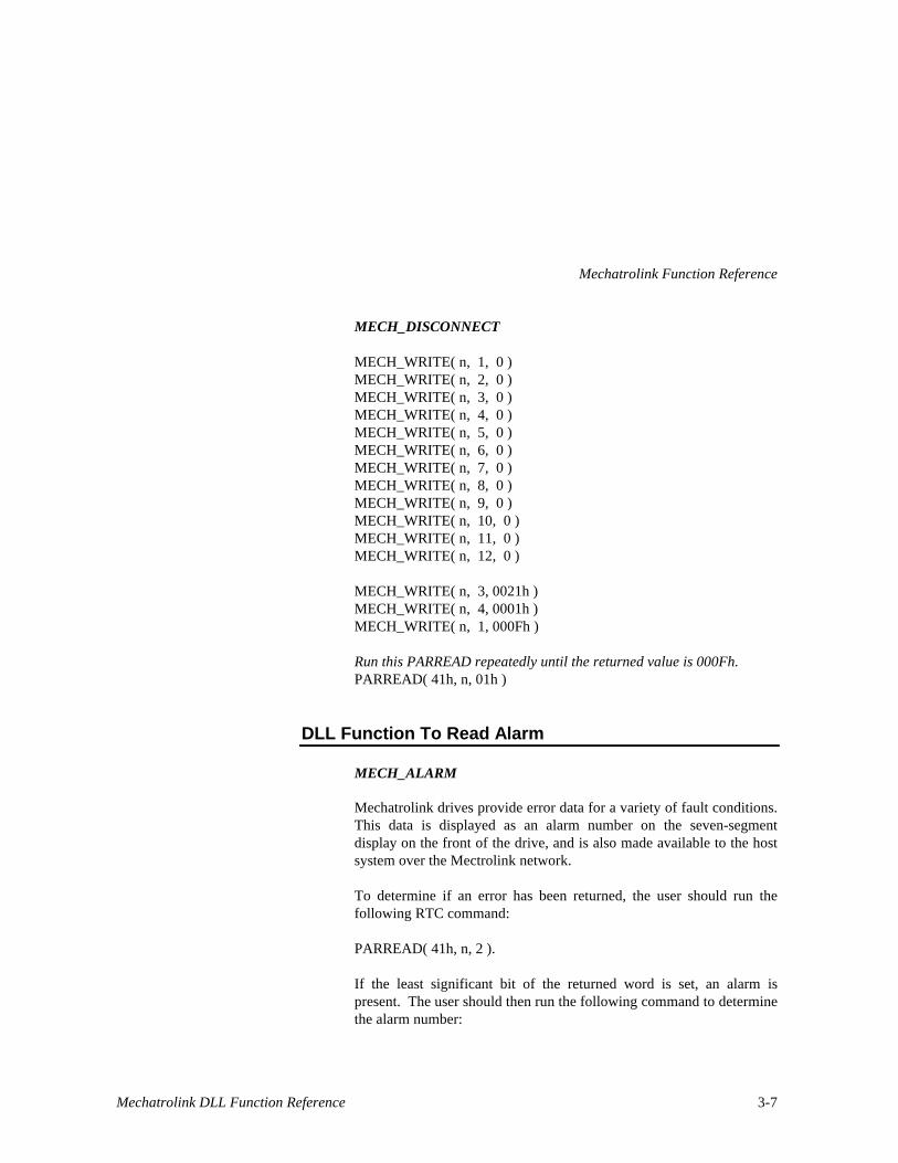
MECH_DISCONNECT
MECH_WRITE( n, 1, 0 )MECH_WRITE( n, 2, 0 )MECH_WRITE( n, 3, 0 )MECH_WRITE( n, 4, 0 )MECH_WRITE( n, 5, 0 )MECH_WRITE( n, 6, 0 )MECH_WRITE( n, 7, 0 )MECH_WRITE( n, 8, 0 )MECH_WRITE( n, 9, 0 )MECH_WRITE( n, 10, 0 )MECH_WRITE( n, 11, 0 )MECH_WRITE( n, 12, 0 )
MECH_WRITE( n, 3, 0021h )MECH_WRITE( n, 4, 0001h )MECH_WRITE( n, 1, 000Fh )
Run this PARREAD repeatedly until the returned value is 000Fh.PARREAD( 41h, n, 01h )
DLL Function To Read Alarm
MECH_ALARM
Mechatrolink drives provide error data for a variety of fault conditions.This data is displayed as an alarm number on the seven-segmentdisplay on the front of the drive, and is also made available to the hostsystem over the Mectrolink network.
To determine if an error has been returned, the user should run thefollowing RTC command:
PARREAD( 41h, n, 2 ).
If the least significant bit of the returned word is set, an alarm ispresent. The user should then run the following command to determinethe alarm number:

Mechatrolink Function Reference
3-8
PARREAD( 41h, n, 1 ).
The high byte of the returned word contains the high two digits of thealarm number in binary coded decimal format.
DLL Function To Clear Alarm
MECH_CLRALARM
To clear an alarm, all axes are to be brought to a stop, the system isunblocked using the MECH_BLOCK RTC, and the following sequenceis run.
MECH_WRITE( n, 1, 0 )MECH_WRITE( n, 2, 0 )MECH_WRITE( n, 3, 0 )MECH_WRITE( n, 4, 0 )MECH_WRITE( n, 5, 0 )MECH_WRITE( n, 6, 0 )
Run Mechatrolink disconnect command.MECH_WRITE( n, 1, 0006h )
Run this PARREAD repeatedly until the returned value is 0006h.PARREAD (41h, n, 01h )
Mechatrolink Function Reference
Mechatrolink DLL Function Reference 3-9
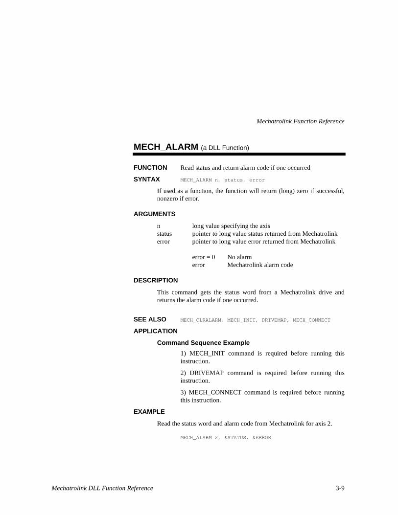
MECH_ALARM (a DLL Function)
FUNCTION Read status and return alarm code if one occurred
SYNTAX MECH_ALARM n, status, error
If used as a function, the function will return (long) zero if successful,nonzero if error.
ARGUMENTS
n long value specifying the axisstatus pointer to long value status returned from Mechatrolinkerror pointer to long value error returned from Mechatrolink
error = 0 No alarmerror Mechatrolink alarm code
DESCRIPTION
This command gets the status word from a Mechatrolink drive andreturns the alarm code if one occurred.
SEE ALSO MECH_CLRALARM, MECH_INIT, DRIVEMAP, MECH_CONNECT
APPLICATION
Command Sequence Example
1) MECH_INIT command is required before running thisinstruction.
2) DRIVEMAP command is required before running thisinstruction.
3) MECH_CONNECT command is required before runningthis instruction.
EXAMPLE
Read the status word and alarm code from Mechatrolink for axis 2.
MECH_ALARM 2, &STATUS, &ERROR

Mechatrolink Function Reference
3-10
MECH_CLRALARM (a DLL Function)
FUNCTION Clears Mechatrolink alarm
SYNTAX MECH_CLRALARM n
If used as a function, the function will return (long) zero if successful,nonzero if error.
ARGUMENTS
n long value specifying the axis
DESCRIPTION
This command will clear an alarm on a Mechatrolink drive.
SEE ALSO MECH_ALARM, MECH_INIT, DRIVEMAP, MECH_CONNECT
APPLICATION
Command Sequence Example
1) MECH_INIT command is required before running thisinstruction.
2) DRIVEMAP command is required before running thisinstruction.
3) MECH_CONNECT command is required before runningthis instruction.
EXAMPLE
Clear alarm on axis 2.
MECH_CLRALARM 2

Mechatrolink Function Reference
Mechatrolink DLL Function Reference 3-11
MECH_INIT (a DLL Function)
FUNCTION Enables Mechatrolink syetm
SYNTAX MECH_INIT
If used as a function, the function will return a (long) zero if successful,nonzero if error.
ARGUMENTS
none
DESCRIPTION
This command enables the Mechatrolink system for all axes in asystem using an Mx4 system. It must always be sent before any otherMechatrolink commands.
SEE ALSO DRIVEMAP,MECH_SCALE,MECH_BLOCK
APPLICATION
A necessary function before all Mechatrolink commands.
Command Sequence Example
No preparation is required before running this instruction.
EXAMPLE
Enable the Mechatrolink system for all axes.
MECH_INIT

Mechatrolink Function Reference
3-12
DRIVEMAP (DLL Function also see RTC)
FUNCTION Maps an axis number to a Mechatrolink drive number
SYNTAX DRIVEMAP n, drv
If used as a function, the function will return (long) zero if successful,nonzero if error.
ARGUMENTS
n long value specifying the axis to be mappeddrv byte value specifying the Mechatrolink drive number
DESCRIPTION
This command must be executed for each axis connected to aMechatrolink drive. To unmap a drive set the drive number to zero.
Note – the axis and drive numbers are commonly the same. A drivenumber is what is set on the front pannel of a Yaskawa Sigma drive viaa rotary numerically marked switch. So, if this switch is set to 3, thedrive value, drv is equal to 3 and you may use the same value (i.e. 3)for n. This command must be used after MECH_INIT.
SEE ALSO MECH_INIT, MECH_SCALE, MECH_BLOCK
Mechatrolink Function Reference
Mechatrolink DLL Function Reference 3-13
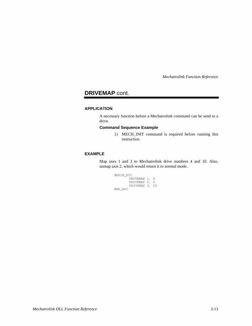
DRIVEMAP cont.
APPLICATION
A necessary function before a Mechatrolink command can be send to adrive.
Command Sequence Example
1) MECH_INIT command is required before running thisinstruction.
EXAMPLE
Map axes 1 and 3 to Mechatrolink drive numbers 4 and 10. Also,unmap axis 2, which would return it to normal mode.
BEGIN_RTCDRIVEMAP 1, 4DRIVEMAP 2, 0DRIVEMAP 3, 10
END_RTC
Mechatrolink Function Reference
3-14
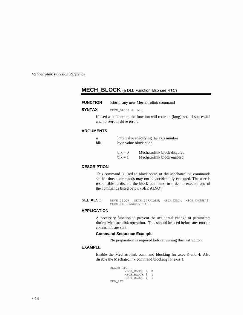
MECH_BLOCK (a DLL Function also see RTC)
FUNCTION Blocks any new Mechatrolink command
SYNTAX MECH_BLOCK n, blk
If used as a function, the function will return a (long) zero if successfuland nonzero if drive error.
ARGUMENTS
n long value specifying the axis numberblk byte value block code
blk = 0 Mechatrolink block disabledblk = 1 Mechatrolink block enabled
DESCRIPTION
This command is used to block some of the Mechatrolink commandsso that those commands may not be accidentally executed. The user isresponsible to disable the block command in order to execute one ofthe commands listed below (SEE ALSO).
SEE ALSO MECH_CLOOP, MECH_CLRALARM, MECH_ENCO, MECH_CONNECT,MECH_DISCONNECT, CTRL
APPLICATION
A necessary function to prevent the accidental change of parametersduring Mechatrolink operation. This should be used before any motioncommands are sent.
Command Sequence Example
No preparation is required before running this instruction.
EXAMPLE
Enable the Mechatrolink command blocking for axes 3 and 4. Alsodisable the Mechatrolink command blocking for axis 1.
BEGIN_RTCMECH_BLOCK 1, 0MECH_BLOCK 3, 1MECH_BLOCK 4, 1
END_RTC
Mechatrolink Function Reference
Mechatrolink DLL Function Reference 3-15
MECH_INIT (an RTC Function)
FUNCTION Mechatrolink Enable
DPR ORDER command code
USAGE Host (command code: 91h)
ARGUMENTS
none
DESCRIPTION
This command enables the Mechatrolink system for all axes in the Mx4firmware. It must be send before any other Mechatrolink commands.
SEE ALSO DRIVEMAP, MECH_WRITE, MECH_BLOCK
EXAMPLE
No arguments needed.

Mechatrolink Function Reference
3-16
DRIVEMAP (an RTC Function)
FUNCTION Map an Axis to a Mechatrolink Drive Number
DPR ORDER command code, n , drv1, … , drv4
USAGE Host (command code: 92h)
ARGUMENTS
n a single byte, bit coding the axes involveddrvx a single byte value the drive number to map to axis x
DESCRIPTION
This command must be executed for each axis connected to aMechatrolink drive. It maps a Mx4 axis number to a Mechatrolinkdrive number. This allows the normal motion commands to beexecuted without any modification. To unmap an axis, send a drivenumber of zero.
SEE ALSO MECH_INIT, MECH_WRITE, MECH_BLOCK
EXAMPLE
Set the axes 1 and 3 to Mechatrolink drive numbers 1 and 4.
drv1 = 1drv3 = 4
The values of the RTC arguments are:
n : 05hdrv1 : 01hdrv3 : 04h

Mechatrolink Function Reference
Mechatrolink DLL Function Reference 3-17
MECH_BLOCK (an RTC Function)
FUNCTION Map an Axis to a Mechatrolink Drive Number
DPR ORDER command code, n, blk1, … , blk4
USAGE Host (command code: 95h)
ARGUMENTS
n a single byte, bit coding the axes involvedblk x a single byte value block code
blk = 0 Mechatrolink block disabledblk = 1 Mechatrolink block enabled
DESCRIPTION
This command is used to block some of the Mechatrolink commandsso that those commands may not be accidentally executed. The user isresponsible to disable the block command in order to execute one ofthe commands listed below (SEE ALSO).
SEE ALSO MECH_WRITE
EXAMPLE
Enable the Mechatrolink command blocking for axis 2 anddisable the Mechatrolink command blocking for axis 1.
blk1 = 0blk2 = 1
The values of the RTC arguments are:
n : 03hblk1 : 00hblk2 : 01h
Mechatrolink Function Reference
3-18
MECH_WRITE (an RTC Function)
FUNCTION Write a word to Mechatrolink transmit buffer
DPR ORDER command code, n, offset, value
USAGE Host (command code: 93h)
ARGUMENTS
n a single byte, bit coding the axes involvedoffset a single byte the offset to write in the axis transmit buffervalue a single word the value to write into the transmit buffer
DESCRIPTION
This command is used to write a word to the Mechatrolink transmitbuffer. It is used to send Mechatrolink commands (See MechatrolinkUser Guide for command format) to the drive that is mapped an axis.
SEE ALSO DRIVEMAP, MECH_INIT, MECH_BLOCK
EXAMPLE
For the Mechatrolink drive mapped to axis 1 write 0Fh tooffset 2.
offset = 2value = 0Fh
The values of the RTC arguments are:
n : 01hoffset : 02hvalue : 0Fh
Mechatrolink Function Reference
Mechatrolink DLL Function Reference 3-19
PARREAD (an RTC Function)
FUNCTION Parameter Readback
DPR ORDER command code, n, m, offset
USAGE Host (command code: 5Eh)
ARGUMENTS
n a single byte, which indicates the parameters to echo.
n=40h Read word from Mechatrolink transmit buffern=41h Read word from Mechatrolink receive buffern=42h Drive mapping for axes 1, 2, 3, and 4
m a byte value, which codes the axis, involved
offset a byte value the offset to read
DESCRIPTION
Upon the execution of this command, Mx4 echoes the desiredparameters to DPR locations 0B8h - 0BFh. "m" is echoed to DPRlocation 0B7h if the parameters are ready in the DPR. Parameters maytake more than 5ms to echo back to the DPR. Host can use thefollowing algorithm:
1. write m to DPR location 3C3h2. write 0 to DPR location 0B7h3. write RTC command code to DPR location 3C2h4. poll DPR location 0B7h until m is echoed read the data from DPR
location 0B8h - 0BFh
Mechatrolink Function Reference
3-20
PARREAD cont.
DATA FORMAT
For each type of parameter, DPR locations 0B8h - 0BFh areinterpreted differently. The following shows the format foreach type of parameter:
1. Mechatrolink transmit buffer (n=40h)
0B8h low byte of value at offset of axis m0B9h high byte of value at offset of axis m0BAh : not used0BFh
2. Mechatrolink receive buffer (n=41h)
0B8h low byte of value at offset of axis m0B9h high byte of value at offset of axis m0BAh : not used0BFh
3. Drive Mapping (n=42h)
0B8h drive number mapped to axis 10B9h drive number mapped to axis 20BAh drive number mapped to axis 30BBh drive number mapped to axis 40BCh : not used0BFh
Mechatrolink Function Reference
Mechatrolink DLL Function Reference 3-21
PARREAD cont.
SEE ALSO none
EXAMPLE
Read a word from the Mechatrolink receive buffer of axis 2 at offset 3.
offset = 3
The values of the RTC arguments are:
n : 40hm : 02hoffset : 03h
Read drive mapping .
The values of the RTC arguments are:
n : 42h


