27
1 Signal Conditioning
1
Signal Conditioning
2
Chapter Objective
• To understand the important of signal conditioning circuits
• To design the signal conditioner circuits and make the signals from sensors/transducers suitable for the next stage, i.e. Control System
• To understand the standard signals for industrial

3
Standard Signal for Industrial Process
• Electrical: current 4-20 mA, voltage 1-5 Volt
• Mechanical: 3-15 psi
Normally, sensors/transducers didn’t provide directthese standard signals. Therefore, an interfacingcircuit is required between sensors/transducersand standard industrial instrument.
4
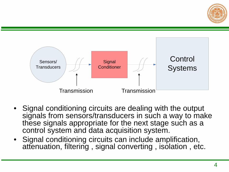
• Signal conditioning circuits are dealing with the output signals from sensors/transducers in such a way to make these signals appropriate for the next stage such as a control system and data acquisition system.
• Signal conditioning circuits can include amplification, attenuation, filtering , signal converting , isolation , etc.
Sensors/Transducers
Control Systems
Signal Conditioner
Transmission Transmission
5
Basic idea
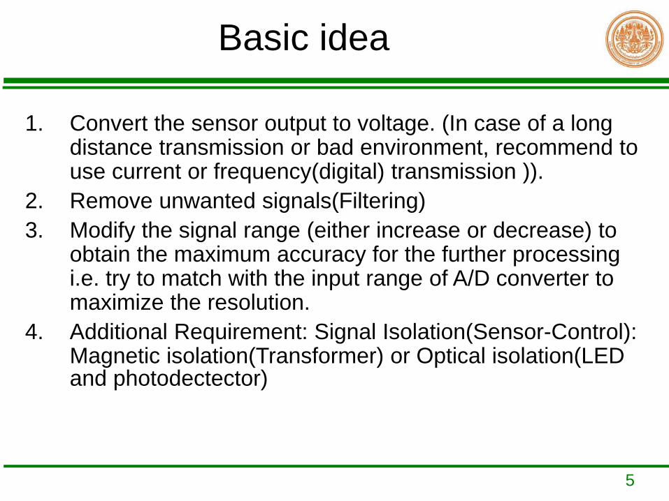
1. Convert the sensor output to voltage. (In case of a long distance transmission or bad environment, recommend to use current or frequency(digital) transmission )).
2. Remove unwanted signals(Filtering)3. Modify the signal range (either increase or decrease) to
obtain the maximum accuracy for the further processing i.e. try to match with the input range of A/D converter to maximize the resolution.
4. Additional Requirement: Signal Isolation(Sensor-Control): Magnetic isolation(Transformer) or Optical isolation(LED and photodectector)

6
Common Signal Conditioning
• Voltage to Voltage:-Inverting Amp-Non-inverting Amp-Summing and Subtracting Amp -Difference Amp-Instrumentation Amplifier(IA)-Zero and Span adjustment
• Voltage to Current and Current to Voltage• Voltage to Frequency and Frequency to Voltage• Optoisolation Circuit• Filtering: Passive and Active

7
Instrumentation Amplifier(IA)• IA is dedicated differential amplifier.• It is optimized for a signal conditioning for low-level signals in large
amounts of noises. • Gain is adjustable by a single resistor.• Finite, accurate and stable gain, usually between 1 and 1000.• Extremely high input impedance.• Extremely low output impedance• Extremely high CMRR(Common Mode Rejection Ratio). • CMRR is the ratio of the gain of the amplifier for differential-mode
signals (signals that are different between the two inputs) to the gain of the amplifier for common-mode signals (signals that are the same at both inputs).
vd
vcm
ACMRRA
= outvd
VAV V+ −=
− ( ) / 2out
vcmVA
V V+ −=+

8
• 2 Stages configuration:input stage and unity-gain difference amplifier stage- Input stage(voltage follower configuration): allows high input impedance to both input
and the gain is set by only one resistor.+ eliminate common-mode signal- Unity-gain difference amplifier stage:
9
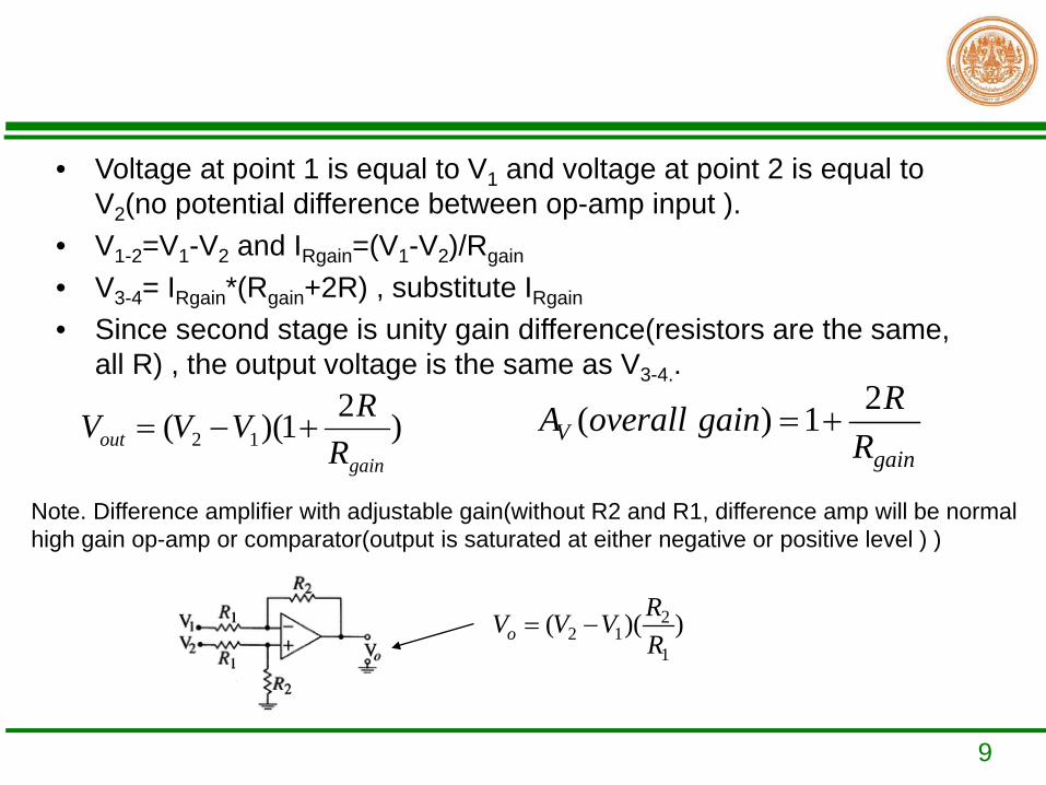
• Voltage at point 1 is equal to V1 and voltage at point 2 is equal to V2(no potential difference between op-amp input ).
• V1-2=V1-V2 and IRgain=(V1-V2)/Rgain
• V3-4= IRgain*(Rgain+2R) , substitute IRgain
• Since second stage is unity gain difference(resistors are the same, all R) , the output voltage is the same as V3-4..
)21)(( 12gain
out RRVVV +−=
2( ) 1Vgain
RA overall gainR
= +
Note. Difference amplifier with adjustable gain(without R2 and R1, difference amp will be normal high gain op-amp or comparator(output is saturated at either negative or positive level ) )
22 1
1( )( )o
RV V VR
= −
10
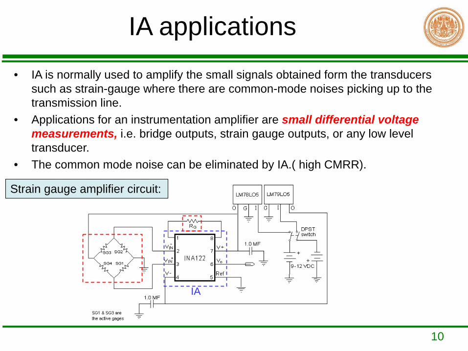
IA applications• IA is normally used to amplify the small signals obtained form the transducers
such as strain-gauge where there are common-mode noises picking up to the transmission line.
• Applications for an instrumentation amplifier are small differential voltage measurements, i.e. bridge outputs, strain gauge outputs, or any low level transducer.
• The common mode noise can be eliminated by IA.( high CMRR).
Strain gauge amplifier circuit:
IA
11
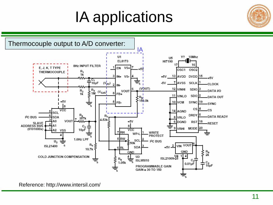
IA applicationsThermocouple output to A/D converter:
Reference: http://www.intersil.com/
IA
12
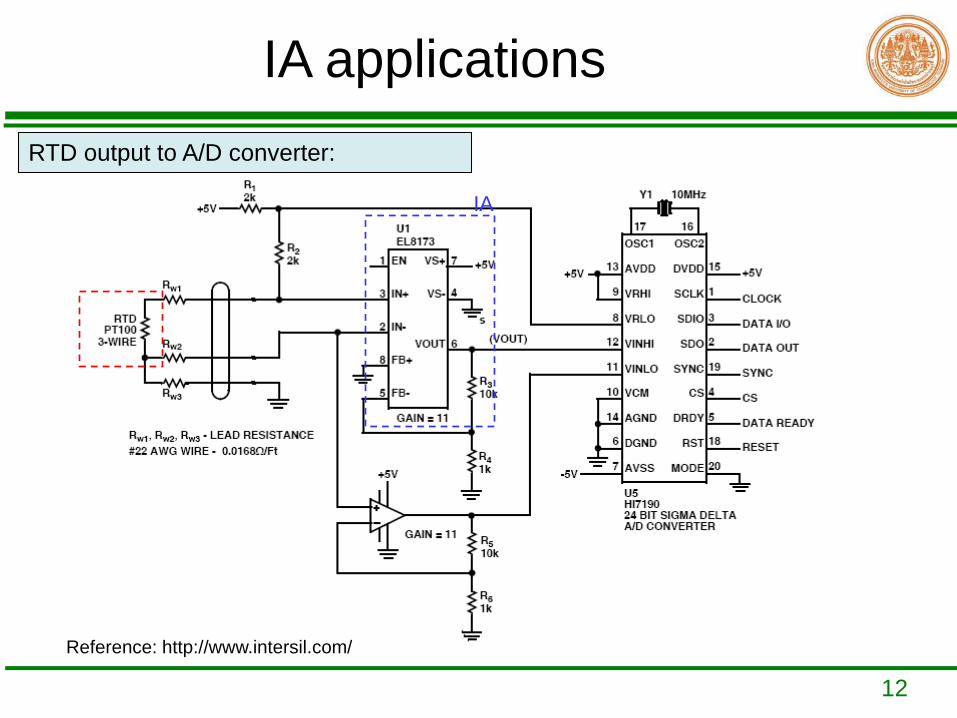
IA applicationsRTD output to A/D converter:
Reference: http://www.intersil.com/
IA
13
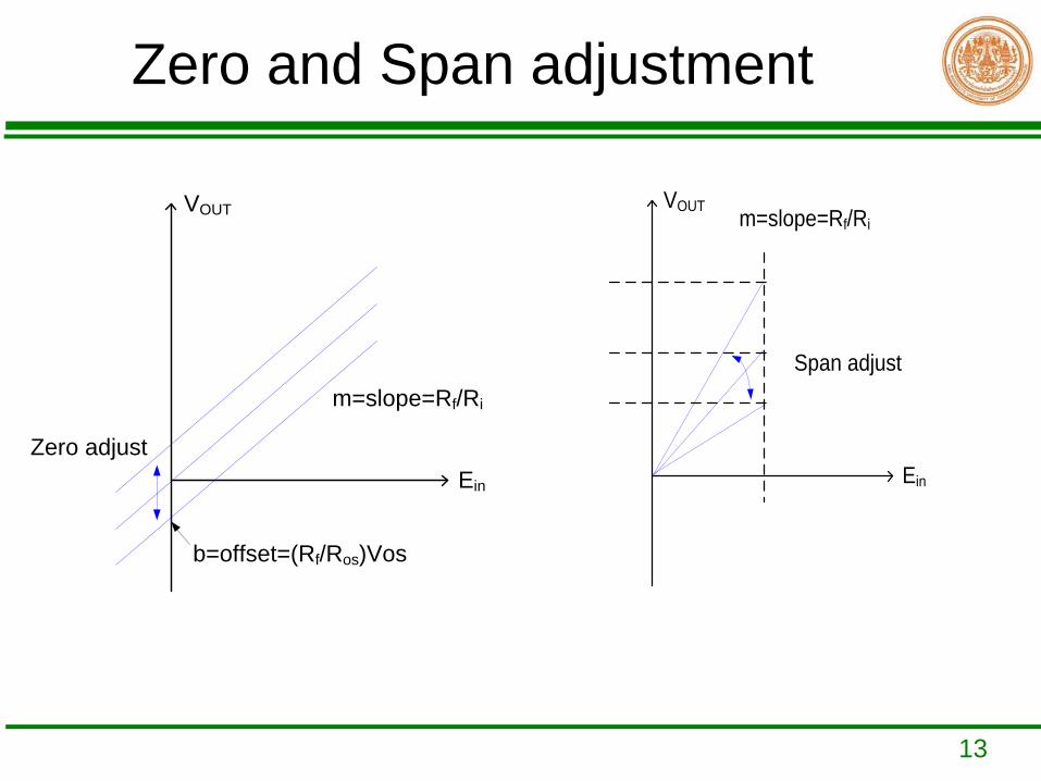
Zero and Span adjustment
Ein
VOUT
m=slope=Rf/Ri
b=offset=(Rf/Ros)Vos
Zero adjustEin
VOUT m=slope=Rf/Ri
Span adjust

14
Zero and Span adjustment
• Rf and Ri adjust the span(gain-slope)• ±Vos adjust the zero(offset)
+
_
Rf
VOUT1= -(mx+b)Ri
Ros
R
+
_
R±Vos
Ein
VOUT2= (mx+b)
Inverting Summing AmpInverting Amp
osos
fin
i
fOUT V
RR
ERR
V +=2
15
Example 1
• Design the zero and span converter using OP-AMP 741 and supply ±5V to convert Ein (-0.25 V to 0.25 V) to Vout (0 V to 5 V)

16
Solution

17
Solution
18
Example 2• Design a signal conditioning circuit to measure the speed of motor using
RE.0444 NV B C1X20 CA IP44 11X30 (DC Tachogenerator) as sensor (Datasheet is given below). The motor speed to be measured is between 0 to 200 revolution per minute( rpm ). The desired output voltage is 0 to 5 V for connecting to an analog input port of microcontroller.


20
Homework
• Design the zero and span converter using OP-AMP 741 working with power supplies ±5 V to convert Ein (2 V to 4 V) to Vout (0 V to 5 V). Students must use standard resistor values in the design.

Standard Variable Resistors
Standard Fixed Value Resistors

22
Isolated Triggering Circuit
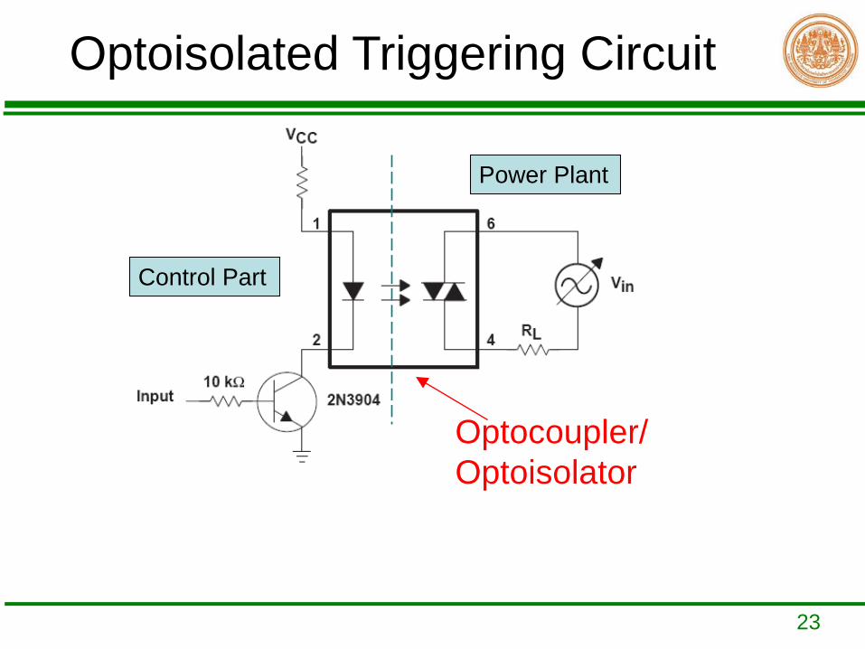
• For a safety consideration, an isolation between control circuit(low voltage, i.e. 5V triggering pulse) and power circuit(high voltage, i.e. 220V-few kV power plant) is very necessary. The isolation circuit prevents a damage of expensive devices used in control part. The isolation circuit can be implemented by:
1. Optoisolator2. Transformer
23
Optoisolated Triggering Circuit
Optocoupler/Optoisolator
Control Part
Power Plant

24
Optocoupler
25
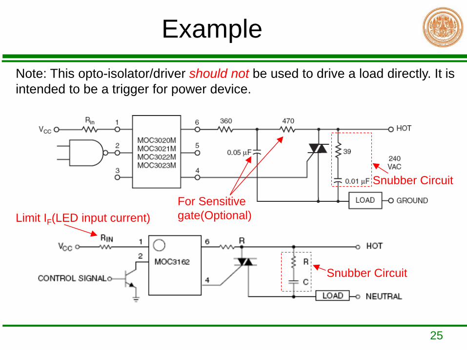
Example
Snubber Circuit
For Sensitive gate(Optional)
Note: This opto-isolator/driver should not be used to drive a load directly. It is intended to be a trigger for power device.
Snubber Circuit
Limit IF(LED input current)

26
Each output consists of a MOC3041 Optoisolator Triac Driver followed by a TIC226 TRIAC.
This circuit receives separated 8 inputs and switches the lights off/on when it receives one. The light will on when In 1-8 is Low/High ??
27
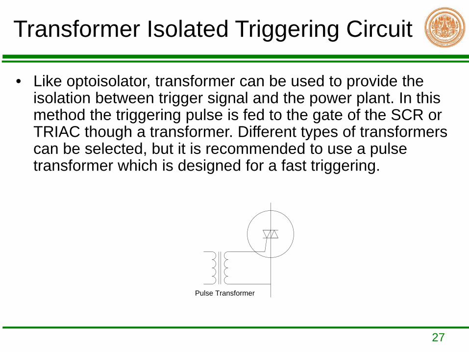
Transformer Isolated Triggering Circuit
• Like optoisolator, transformer can be used to provide the isolation between trigger signal and the power plant. In this method the triggering pulse is fed to the gate of the SCR or TRIAC though a transformer. Different types of transformers can be selected, but it is recommended to use a pulse transformer which is designed for a fast triggering.
Pulse Transformer


