1 Modern Observational/Instrumentation Techniques Astronomy 500 Andy Sheinis, Sterling 5520,2-0492 [email protected]MW 2:30, 6515 Sterling Office Hours: Tu 11-12 Signal-to-Noise (S/N) • Signal=R * • t time detected e-/second • Consider the case where we count all the detected e- in a circular aperture with radius r. I sky r r
Transcript
1
ModernObservational/Instrumentation
TechniquesAstronomy 500
Andy Sheinis, Sterling 5520,[email protected] 2:30, 6515 SterlingOffice Hours: Tu 11-12
Signal-to-Noise (S/N)
• Signal=R*• t time
detected e-/second
• Consider the case where we count all the detected e- in a circular aperture with radius r.
I
sky
r
r
2
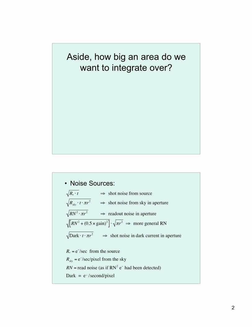
Aside, how big an area do wewant to integrate over?
• Noise Sources:
!
R* " t # shot noise from source
Rsky " t " $r2 # shot noise from sky in aperture
RN2" $r2 # readout noise in aperture
RN2 + (0.5 % gain)2[ ] " $r2 # more general RN
Dark " t " $r2 # shot noise in dark current in aperture
R* = e&/sec from the source
Rsky = e&/sec/pixel from the sky
RN = read noise (as if RN2 e& had been detected)
Dark = e_ /second/pixel
3
S/N for object measured in aperture with radius r: npix=#of pixels in the aperture= πr2
!
R*t
R* " t + Rsky " t " npix + RN +gain
2
#
$ %
&
' ( 2
" npix +Dark " t " npix)
* +
,
- .
1
2
Signal
Noise
!
(R*" t)
2
All the noise terms added in quadratureNote: always calculate in e-
Noise from sky e- in aperture
Noise from the darkcurrent in aperture
Readnoise in aperture
RskySignal from the sky background ispresent in every pixel of theaperture. Because each instrumentgenerally has a different pixel scale,the sky brightness is usuallytabulated for a site in units ofmag/arcsecond2.
• First and foremost: Scientific Justification!– Give context– Clearly state what unanswered questions are to be
addressed– Clearly state what you will do new or better
• Look Competent and Smart– Do S/N and exposure time calculations– Defend choice of filters/spectral resolution sample size etc.
Observing
• Rule #1 -- keep collecting photons!• Know your S/N targets• Plan the night out carefully ahead of
time• Useful tools:
– Aircharts
10
• Right Ascension (RA) andDeclination (Dec) are equatorial skycoordinates
• Like longitude and latitude(respectively) on the surface of theEarth but fixed on the sky
• Aligned with the Earth’s axis so theRA and Dec for celestial objectschanges as the Earth’s orbitprecesses. Need to specify the“epoch” of the coordinates.
Hour angles and airmass• The sidereal time gives the
right ascension that ispassing through themeridian. Index point isVernal equinox, 12h isoverhead at local midnight onMarch 21. Sky advances 2hours per month.
• The hour angle is the timebefore or after a particularRA is at the meridian.HA=LST-RA
• Airmass is a combination ofthe HA and the differencebetween the telescopelatitude and the pointingdeclination.Airmass~sec(zenith angle)
11
• IRAF Airchart in the mtools packages is very handy.• Typically observe with airmass=X<2• Atmospheric dispersion can be a problem for X>1.5• http://www.eso.org/observing/bin/skycalcw/airmass
There are oftenother limits thatgovern where youcan point in the sky.
East
North
1h2h
3h
Dec=-30
12
Decisions before observing• Sometimes, the gain in e-/DN for the system• On-chip binning?
– Smaller files (not important)– Faster readout time (can be important)– Less readout noise per area detector (can be important)
• For direct imaging in broadband filters, readnoise is very rarelyan issue. You want to have the FWHM of point sources to be atleast 2.5 pixels to properly sample the PSF. If you areoversampled, that doesn’t usually have any dire consequences.The readout time can be a deciding factor.
Binning for spectra
.• Sometimes, RN is asignificant componentof the noise. Havingfewer pixels under thespectrum reduces thenoise in a resolutionelement.
• Binning in Spectraldirection can reduceresolution
Spatial direction
• Binning in the spatial direction can compromise fitting the sky lines
13
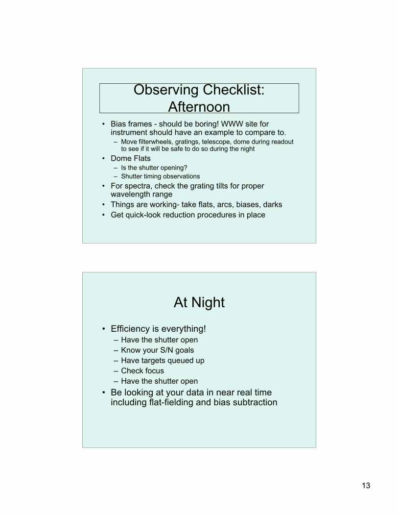
Observing Checklist:Afternoon
• Bias frames - should be boring! WWW site forinstrument should have an example to compare to.– Move filterwheels, gratings, telescope, dome during readout
to see if it will be safe to do so during the night• Dome Flats
– Is the shutter opening?– Shutter timing observations
• For spectra, check the grating tilts for properwavelength range
• Things are working- take flats, arcs, biases, darks• Get quick-look reduction procedures in place
At Night
• Efficiency is everything!– Have the shutter open– Know your S/N goals– Have targets queued up– Check focus– Have the shutter open
• Be looking at your data in near real timeincluding flat-fielding and bias subtraction
14
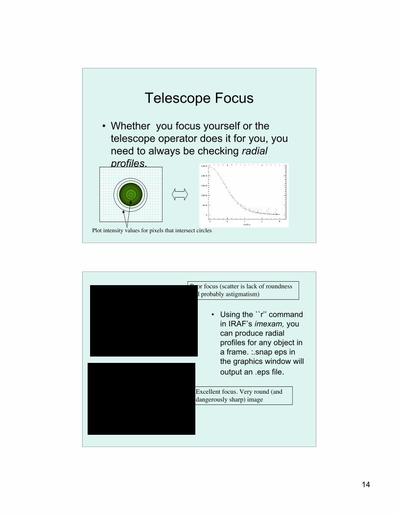
Telescope Focus
• Whether you focus yourself or thetelescope operator does it for you, youneed to always be checking radialprofiles.
Plot intensity values for pixels that intersect circles
• Using the ``r’’ commandin IRAF’s imexam, youcan produce radialprofiles for any object ina frame. :.snap eps inthe graphics window willoutput an .eps file.
Poor focus (scatter is lack of roundnessand probably astigmatism)
Excellent focus. Very round (anddangerously sharp) image
15
Well focussed star
Saturated star
Galaxy
Way out of focus (donut).
16
Focus frames
1. Set focus, start exposure.2. Pause exposure, move
telescope, change focus3. Repeat4. Make a double telescope
move on the last focusvalue, then read out
Splitting Exposures• How long to expose? Once in the sky-limited regime,
the S/N only depends on the total exposure time.There is only the CCD readout time penalty to bepaid by splitting long exposures into multiple shorterexposure.
• Why do shorter exposures?– Cosmic ray rejection– Increase dynamic range– ``in-field dithering’’ along slit or on the sky can help with flat
• There are two types of instrumentalsignature to remove:– Additive:
• Bias Level• Bias Structure• Dark Counts
– Multiplicative:• Q.E. variations on all scales
Constant # of countsadded independent ofthe brightness of thesource(s).
Constant fractionaleffect
18
Bias Correction
• Bias level and any y (along columns)gradient is taken out via overscansubtraction.
• Bias structure is taken out bysubtracting a zero-level frame.
• In IRAF ccdproc takes care of both.
Overscan
• After reading out theCCD `real’ pixels, youcan continue to read outvirtual pixels and recordthe bias level and readnoise of the amplifiers.These virtual pixels arecalled the overscanregion
Active area of CCD
Row orline #
Column # overscan region
19
Two amplifier overscan
20
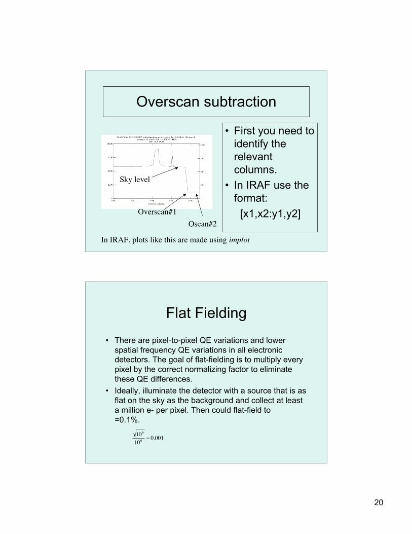
Overscan subtraction
• First you need toidentify therelevantcolumns.
• In IRAF use theformat:
[x1,x2:y1,y2]
Sky level
Overscan#1Oscan#2
In IRAF, plots like this are made using implot
Flat Fielding
• There are pixel-to-pixel QE variations and lowerspatial frequency QE variations in all electronicdetectors. The goal of flat-fielding is to multiply everypixel by the correct normalizing factor to eliminatethese QE differences.
• Ideally, illuminate the detector with a source that is asflat on the sky as the background and collect at leasta million e- per pixel. Then could flat-field to=0.1%.
!
106
106
= 0.001
21
Flat Fielding
• If you could illuminate the CCD uniformly,then normalize the mean to 1, this imagecould be divided into every frame.
• For direct imaging, usually use a combinationof:– Dome Flats– Twilight Flats– Dark Sky Flats
Dome Flats
• Put some quartz (hot, continuum source) lamps onthe telescope and illuminate a white screen or spoton the dome.
• These often don’t work very well for two reasons:– The lamps are always too cool (red)– The dome is not even close to infinity and usually illuminates
the primary differently than the sky
• But, you can collect a lot of photons during the day
22
Twilight Flats
• These often work pretty well• The Sun is pretty hot, the scattering
surface illuminates the telescope justlike the dark night sky
• Doesn’t use dark time
Dark-sky Flats
• These tend to work very well. Theymatch the sky perfectly
• They sometimes require useful darktime
• They sometimes contain fringes
23
Stars and Galaxies
• For twilight and dark sky flats you have a problem inthat they contain stars and galaxies. The usual trick isto move the telescope between exposures and thendo a non-registered stack of the frames in each filter.
• Median or better yet minmax rejection (for example,in the frame combining can effectively eliminate allthe stars and galaxies in the combined flat.
Minmax rejection
Pixel value: 1000 200 180 180
Average with minmax rejection, reject 2 highest value averaginglowest two will give the sky value. NOTE! Must normalizeframes to common mean or mode before combining! Sometimesit is necessary to pre-clean the frames before combining.
24
Combining Frames
• In IRAF, imcombine is the task tocombine frames.– combine=average– reject=minmax– scale=mode– nlow=0– nhigh=2
Flat fielding tricks• Combine domes (high counts, bad illumination) with
dark sky flats (low counts, excellent illumination).1. Spatially smooth (or fit low-order surface to) both combined
dome and combined dark sky. > sDome, sDark2. Remove dome low-spatial-frequency pattern:
Dome/sDome3. sDark is the sky flat with the low-f pattern already removed.4. Best of both worlds is (Dome/sDome) x sDark
25
PFCam flat fieldsI-band
V-band
U-band
Dust on filter
Rings due to non uniform thinning
Note differences with color.This means that objects withdifferent spectra will be flat-fielded slightly incorrectly.
Two amplifer readout
26
Flat-field tests
1. Take cuts through your flat-fieldedframes and make sure the sky is flat(check corners). IRAF implot
2. In blank areas, make sure the pixel-to-pixel variations are consistent withshot noise from the sky level. IRAFimexam and the `m’ key.