16,8, PHILIPS TECHNICAL REVIEW ' VOL. 8, No. 6 SIGNALLING IN CARRIER TELEPHONY by F. A. de GROO~. 621.395.63 :621.395.44 The establishing of a connection betw~en two subscribers of a telephone network requires the transmission of different signals from the subscribers' instruments to the, exchange and vjce versa. In local.networks this signalling is done partly with direct current. Since, however, in the ease of long trunk lines, and especially in the case óf carrier connections, this is impossible, other methods had to be developed. After a short discussion of signalling with alternating current of audio-frequency, the Philips system of sjgnalling with the carrier waves is considered. In the description of the practical execution of this method of signalling special attention is devoted to the I_!lanner,in which inteiferences with the signal and by the signal are avoided, and how,the distortions, which the signals may experience upo~ transmission, can be counteracted. In order to carry on a telephone conversation, it is not enough to have available an installation which is capable of transmitting speech clearly and with- out interferences. Each subscriber must also be able to ring up anyother subscriher. To do this, he must he able to inform the' telephone exchange, t~àt, he wishes a call to he put through; . the exchange' must prepare the connection, warn the subscriber called, inform the subsèriber calling, whèthér or not, the desired line is already engaged, etc.; finally after the conclusion ofthe conversation thé 'exchange must he warned, so 'that 'everything can he .returned to a position of rest. o All these arid any other warnings and communi- - ',cations are accomplished by' certain signals, a~d th~ complex system of aids, which serve for the exci- tation and transmission of these signals, iscalled the . signalling system. . A· signalling system is necessary, not only for local, but also for trunk connections. The problems thereby involved, especially when carrier telephony is used for the trunk connecti?n, will he discussed' in this article. :We shall deal especially with a sig- nalling system, developed by Philips, in which the ~ar~ier waves themselves ~re uscd for the signalling. We shall begin with a simplified description of what happens, in a local telephone conversation, hetween two subscrihers on an auto:matic exchange. Signalling in a· local connection with automatic exchange In fig. 1 the circuit diagram is given of the con- nection between two subscribers a and b,. omit'ting 'all non-essential details. , In the state of rest, the, telephones of the two subscrihers hang on their hooks, the contacts Ha' and Hb are then open, the lines car~y no current, the relays Ra and' Rb are ,released. Upon a lifting up the receiver, the contact Há is' closed' and a direct ~urrent la, furnished by the battery E, he- gins to' flow tlirough the line and the apparatus. This direct current (which, moreover, also serves to feed the carbon microphone M) .energizes the relay Ra and the exchange is by this means in- formed, that a wishes to make a call. The exchange, b~ means of a switching process, which may be b Fig. I... Simplified diagram of the signalling system in a local telephone connection with automatic exchange. M microphone, T telephone, Ha and Hb hook contacts, B bell, C condenser, N cam disc, K contact of dial, la 'qnd Ib line currents, Ra and Rb relays, S selectors. , disregarded here, now makes itself ready to "hear", with whom a wishes to speak. The fact, that the exchange is ready for this, is comni~icated to .a by a so-called dialling' tone', which is sent over the line-by the exchange. Upon hearing this, the sub- scriber begins to dial, i;e. he turns his dial and lets it run baék; during thisrunning back the line current is interrupted (by means' of the cam N and the contact K), this being repeated as many times as .. there are figures in the number dialled. UpoD;each' interruption, the relay Ra releases and thus passes the impulses through to the automatic selectors , set up at the exchange, which thus select ,the line of the subsc~iber being called.' As soon as this line has been found, it is, ascertained, whether i; is free (by whether its relay Rb is "up" or not). If it is not free, the exchange sends over the line to a the "engaged" signal. If the line is free, the exphange sends an alternating current with a fundamental frequency of 16 ri/sec.to b, the' so-called ringing current. The ho~k contact of this subscriber is of
Transcript
16,8, PHILIPS TECHNICAL REVIEW ' VOL. 8, No. 6
SIGNALLING IN CARRIER TELEPHONY
by F. A. de GROO~. 621.395.63 :621.395.44
The establishing of a connection betw~en two subscribers of a telephone network requiresthe transmission of different signals from the subscribers' instruments to the, exchangeand vjce versa. In local.networks this signalling is done partly with direct current. Since,however, in the ease of long trunk lines, and especially in the case óf carrier connections,this is impossible, other methods had to be developed. After a short discussion of signallingwith alternating current of audio-frequency, the Philips system of sjgnalling with thecarrier waves is considered. In the description of the practical execution of this methodof signalling special attention is devoted to the I_!lanner,in which inteiferences with thesignal and by the signal are avoided, and how,the distortions, which the signals mayexperience upo~ transmission, can be counteracted.
In order to carry on a telephone conversation, it isnot enough to have available an installation whichis capable of transmitting speech clearly and with-out interferences. Each subscriber must also beable to ring up anyother subscriher. To do this, hemust he able to inform the' telephone exchange,t~àt, he wishes a call to he put through;
. the exchange' must prepare the connection, warnthe subscriber called, inform the subsèriber calling,whèthér or not, the desired line is already engaged,etc.; finally after the conclusion ofthe conversationthé 'exchange must he warned, so 'that 'everythingcan he .returned to a position of rest.
o All these arid any other warnings and communi-- ',cations are accomplished by' certain signals, a~d th~
complex system of aids, which serve for the exci-tation and transmission of these signals, is called the .signalling system.. A· signalling system is necessary, not only forlocal, but also for trunk connections. The problemsthereby involved, especially when carrier telephonyis used for the trunk connecti?n, will he discussed'in this article. :We shall deal especially with a sig-nalling system, developed by Philips, in which the~ar~ier waves themselves ~re uscd for the signalling.We shall begin with a simplified description of whathappens, in a local telephone conversation, hetweentwo subscrihers on an auto:matic exchange.
Signalling in a· local connection with automaticexchange
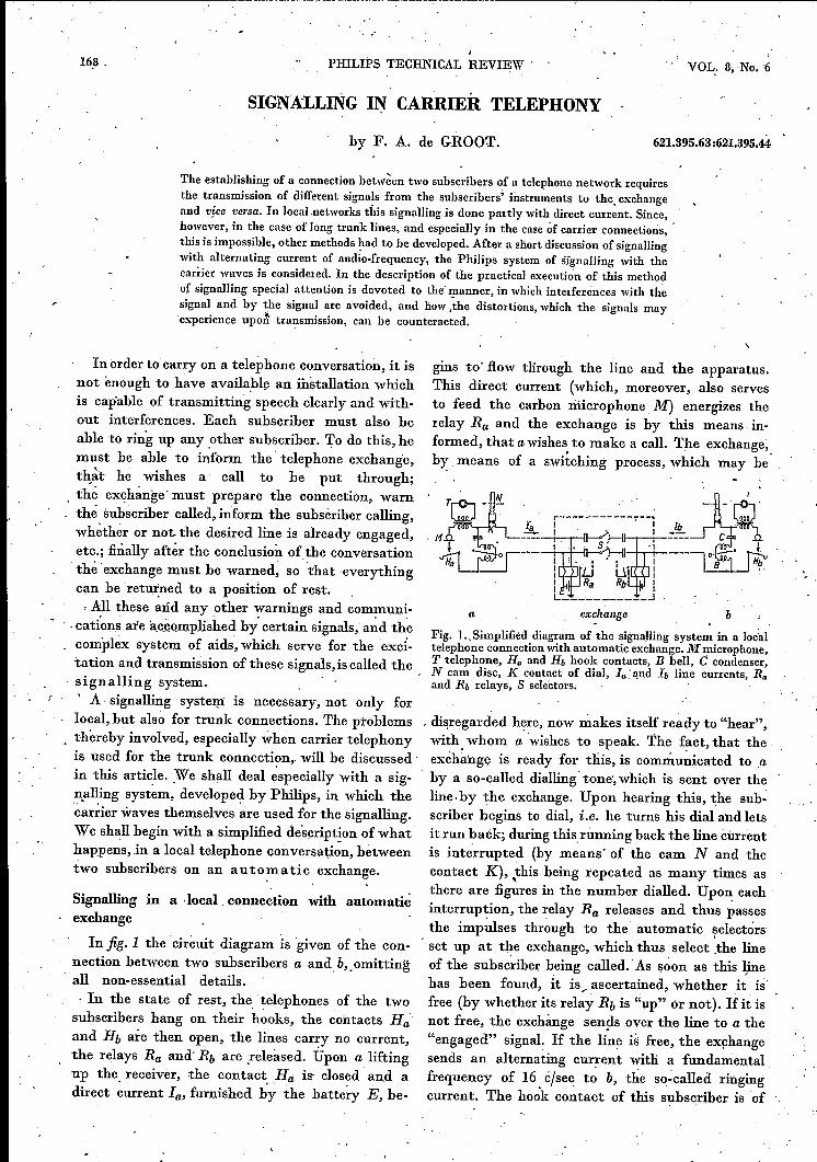
In fig. 1 the circuit diagram is given of the con-nection between two subscribers a and b,.omit'ting'all non-essential details., In the state of rest, the, telephones of the twosubscrihers hang on their hooks, the contacts Ha'and Hb are then open, the lines car~y no current,the relays Ra and' Rb are ,released. Upon a liftingup the receiver, the contact Há is' closed' and adirect ~urrent la, furnished by the battery E, he-
gins to' flow tlirough the line and the apparatus.This direct current (which, moreover, also servesto feed the carbon microphone M) .energizes therelay Ra and the exchange is by this means in-formed, that awishes to make a call. The exchange,b~ means of a switching process, which may be
b
Fig. I...Simplified diagram of the signalling system in a localtelephone connection with automatic exchange. Mmicrophone,T telephone, Ha and Hb hook contacts, B bell, C condenser,N cam disc, K contact of dial, la 'qnd Ib line currents, Raand Rb relays, S selectors.
, disregarded here, now makes itself ready to "hear",with whom a wishes to speak. The fact, that theexchange is ready for this, is comni~icated to .aby a so-called dialling' tone', which is sent over theline-by the exchange. Upon hearing this, the sub-scriber begins to dial, i;e. he turns his dial and letsit run baék; during thisrunning back the line currentis interrupted (by means' of the cam N and thecontact K), this being repeated as many times as..there are figures in the number dialled. UpoD;each'interruption, the relay Ra releases and thus passesthe impulses through to the automatic selectors
, set up at the exchange, which thus select ,the lineof the subsc~iber being called.' As soon as this linehas been found, it is , ascertained, whether i; isfree (by whether its relay Rb is "up" or not). If it isnot free, the exchange sends over the line to a the"engaged" signal. If the line is free, the exphangesends an alternating current with a fundamentalfrequency of 16 ri/sec. to b, the' so-called ringingcurrent. The ho~k contact of this subscriber is of
jUNE i946
"
SIGNALLING IN CARRIER TELEPHONY 169 .
course open, but the alternating current passes the dialling, also for trunk traffic. In the Netherlands,condenser C, which is tuned with the self-induction for example, the 'telephone' network in importantof the bell to 16 cfsec and causes the bell to ring. parts of the country has already been made auto-At the same time the exchange sends a ringing tone matic. In principle, the manner of establishing theover the line to subscriber a? as a sign, that b's bell connection is the same, as described above, foris ringing. As soon as b removes the receiver direct a local call. Suppose, that the subscriber a in Acurrent also begins to flow in his line, the ringing is wishes to speak with subscriber d in D., He lifts. ~stopped by the operation of the relay Rb and the up the receiver, waits until he hears the .dialling'conversation can take place. When the conver- tone of his local exchange A and then dials a eer-sation is ended, the subscribers hàng up their receiv- tain number, upon 'which the local exchangeers again, the direct current in the two lines is . connects him with the trunk exchange B (seefig. 3).'thereby interrupted, the relays Ra and Rb are .released and as a consequence the selectors ànd thevarious relays in the exchange return to theirposition of rest,~ In fig.2 all these happenings are representedgraphiè~lly, by the variation with - time of the
Ia
Fig. 2. Behaviour of the line currents la and h during atelephone call. a) Line of the subscriber making the call, b)line of the subscriber called. 1.Calling signal, 2 dialling signal,3 dialling impulses, 4 ringing current, .'i ringing tone, 6 an-swering signal,.7 speech currents, 8 and 9 clearing signals.,
1
currents la and Jb 'on the lines of the subscrihercalling and the subsoriher called respectively. It isseen that the signalling comprises the followingsignals 1):
The calling signal (1) s~itching -on ,the directcurrent la).. The dialling tone (2).The dialling impulses ~3) interrupting the direct
current Ia~ "The ringing current of 16 eleee (4.).The 'ringing tone or engaged tone (5).The answering signal (6) switching on thè direct
current lb,
The clearing signal (8-9) switching off la and h..
Signalling in trunk traf.fic
, More and more use is being màde of automatic'
a d
4172&
Fig. 3. Diagram of a trunk connection between subscriber aconnected with the local exchangeA ánd subscriber d connee-ted with the local exchange D. Vari.ous neighbouring localexchanges are connected with a trunk exchange (B and C).The line, between local exchange and trunk exchange, is stillconsidered as "local" line. Between the trunk exchanges Band C, which are far apart, lies the trunk line proper.
In this exchange, as a result of new dialling impulses,the selectors find a line to the trunk exchange C.As soon as this line is found, a warning is ~ent to C(a new calling signal). The subscriber now con-tinues to dial and the impulses, then following, .have to be transmitted over the trunk line to C,to cause the selectors there to transmit to a Iine,connecting è with the local exchange D. This.exchange now sends the dialling tone back tosubscriber a, who now with his dial sends impulsesover the whole connection to the sel~ctors in' D,which find the line of subscriber d. The exchange Dthen sends the ringing current to d in the manneralready described and at the same time !he ring-ing tone or the engaged tone, as the case may he,is sent back to a. After the conclusion of the call; a'clearing signal from B to C (or vice versa) is againnecessa:i:Yto break the connection and bring theapparatus back to the position of rest 2).It is thus clear, that practically all of the signals
mentioned for local connections have to be trans-mitted also over the trunk line: calling signal,dialling impulses and clearing signal as signalsintended for the apparatus, further dialling toneand ringing or engaged tone as signals intended
1) In addition to those mentioned h:ere, there are othersignals, such as those for cou,ntmg the calls, measuring, 2) The course of events sketched here is characteristic ofthe duration of a call, etc. Since these do not involve 'the so-called direct system. There. exist also other diallinganything new in the problems to be considered here, systems (registering systems), but' the signals they requirethey will be left out of consideration.' are in principle the same as those with thè direct system.
170 PHILIPS TECHNICAL REVIEW VOL. 8, No.. 6
for the ear of the caller, to let him know what thesituation is 3).
Different methods of signalling
We have seen that for signalling on the localline, as far as the signals intended for the apparatusare concerned, use is made of direct current,which is in any case required 'for the microphone.Direct current is also used for short-distance trunkconnections. For long-distance connections, how-. ever, it is difficult to obtain a satisfactory solutionin this way: the transformers and any necessaryrepeaters in the line cannot transmit the directcurrent directly, so that every transformer andamplifier would have to be shunted by a relaysystem. Through coil-loaded cables, which are oftenused for long distances" no direct current at allmay be transmitted, because the magnetizationthereby caused js detrimental to the propertiesof the loading coils. '
In carrier telephony too, direct current cannot beused for signalling, because here a number of callsare sent through one pair of conductors and onlyone direct current can be sent through a pair ofconductors. The signals therefore have to be trans-mitted in some other way, and, for every speechchannel, there has to be a signal path independentof the other' channels.The method so far commonly used in these cases
is. voice-frequency signalling. .The D.e. sig-t nals occurring on the localline are converted in 'thetrunk exchange into A.C. signals ~ith a frequencyin the audible region, bètween 300 and 2800 cfsec:Since' the trunk line must in any case transmit
. this frequency region, either directly or .modulatedon a carrier wave, the A.C. signals can he imme-diately passed 'on over the trunk line. At the receiv-ing end the signals are converted back into D.C.
_signals by filtering out the signal frequency andactivating a relay with the signal. voltage.
In voice-frequency signalling the calling andclearing signals, which occur on the local line,when the direct current is switched on and offrespectively, cannot be transmitted ill the form inwhich they occur as the result of the switching onand off of the alternating current, because thisalternating current would then have to be main-
3) Ä' connecti'on between two manual exchanges, as far• as the signalling is concerned, is often simpler than one. between two automatic exchanges, since there are nodialling impulses nor signáls=intended for the ear of thesuhscriber calling. The calling and clearing signals arestill necessary, since it is impossible to have an operatorlistening on each line all the time. It is -the dialling impulses,however, that cause the greatest ·technical difficulties, aswe shall see. ' .
tained during the whole conversatien and wouldbe heard by the subscribers as a disturbing whistle.Calling and clearing signals are therefore now givenby A.C.- impulses of a certain length. One speaksin this case of impulse signalling in contrastto continuous signalling with a direct current,where the signal current continues to flow during
,,1 D~Dc-=-III'"h) l~I---'iEI-'a- ~1--'il!r-2 I
'---v--'-'2 '
---~--~- t
34"27
Fig. 4. Transition from continuous signalling with directcurrent (a) to impulse signalling with voice-frequency alter-nating current (11).1 Calling signal, 2 dialling impulses, 3clearing signal.
the whole call. The, dialling impulses, which incontinuous signalling consist of interruptions of thesignal current, are passed on in impulse signallingby A.C. impulses, like the calling and clearingsignals. The transition from continuous signallingto impulse signalling is illustrated in fig. 4. Inpractice, it is realized by a combination of a numberof relays, a relay gro'up.The relay groups make the signalling more compli-
cated and increase the -chance of interferences.Besides this complication, however, there is alsoa fundamental difficulty in the method of voice-frequency signalling. Owing to the fact, that thesignalling frequency is chosen' in the frequency,region of speech, it is possible that the signalling
Fig. 5. Signalling receiver for voice-frequency signalling. 'The instrument has to distinguish, whether an input voltagewith the signalling frequency originates from, a signal, fromspeech or from interferences. For this purpose the inputvoltage is fed to two filters F. and Fd connected in parallel.F. passes the signalling frequency through and damps theother frequencies, Fd damping the signalling frequency andpassing the others through. Thé output voltages of the twofilters are rectified and fed with opposite polarity to the controlgrid of the amplifier valve B. Due to the negative bios fromthe battery E, the amplifier valve does not transmit any anodecurrent, so that the relay Re is released. When a current withthe signalling frequency arrives, a positive voltage occursover RI' the valve, begins to carry current and Re reacts.If, however, other frequencies arrive, simultaneously witlî thesignalling frequency, a negative voltage will occur on R2' andif this is equal to or greater than the voltage on Rl the valveB remains "overbiased" and Rê' does not operate. .
JUNE 1946 SIGNALLING IN CARRIER ',{'ELEPHONY 171
\receiver also reacts to the speech voltages them-selves: if ,thé signalling, frequency occurs in any'intensity in a speech sound the receiver may, forinstance, construe this as a clearing signal and breakthe connection prematurely. In order to preventthis, the signalling receiver must he so constructed,that it can distinguish, whether a voltage with thesignalling frequency originates from signalor from'some other source. Use is often made here of thefact that in speech different frequencies alwaysoccur at the same time, whereas, in signalling only'the signalling,frequency. occurs. The voltages withother frequencies are then used to put the signallingreceiver out of action with the help of connections,which are shown in fig. 5 and explained in the textunderneath. This arrange~ent works satisfactorily, 'but it has the great drawback, that current surgesor loud speech may cause the signalling receiverto he blocked, as a result of which impulses are lostor distorted. '
Cartier wave "signalling
While the method of voice-frequency signallingdescribed, can he used for normal (low-frequency]as_well as for carrier telephone connections, themethod, about to be discussed, is especially intendedfor carrier telephony., With this method, which,was developed by Philips severàl years ago, reactionto speech is out of the question.
In carrier telephony the speech vibrations ofeach call are fed to a modulator, together with acarrier wave of higher frequency. The modulatorconverts the speech vibrations into side bands ofthe carrier wave, butvthanks to suitable connections,does not allow the carrier wave itself to pass, orat least not to any extent worth mentioning 4).The carrier wave itself is thus not transmitted overthe line. In order to be able to bring the transmittedside band - only one is transmitted since the other
'is suppressed in the transmission band filter -hack into the original frequency region, the carrierwave is added again in the demodulator at thereceiving end.
In the new method of signalling, the carrier wavefrequency of each telephone channel is used forsignalling in that channel. Separate oscillators forthe excitati~n' of 'the carrier wave frequencies arenot required, as the carrier waves are also neces-sary for the modulators (and demodulators) andare therefore already excited in- the exchange 5).
') See: F. A. de Groot and P. 'J. den Haan, Modulatorsfor carrier wave telephony, Philips Techn. Rev. 7, 83, 1942.
5) See: D. Goe(J.hart and G. Hepp, PhiJips Techn. Rev. 8,137, 1946.
By means of a transmission relay, the carrier wavecan be applied in each channel to the line behindthe modulator. At the receiving end a selectivereceiver is connected in parallel with the demodu-,lator, which receiver amplifies and rectifies the car- 'rier wave, A receivi.ng relay îsoperated by the D.e.voltage obtained, and this relay passes the, signals _
, to' the respective apparatus in the automaticexchange.
For this method, therefore, a frequency is used,which does not occur in the, modulated speechspectrum, and which gives no audible tone afterdemodulation. In the first place, this makes itpossible to use conti;nuous signalling as is donein local telephony by means of direct current (thecarrier wave itself may in fact also he considered as"displaced direct current" of the correspondingchannel). As a result the above-mentioned relaygroups are made much simpler. On the other hand,continuous signalling, as we shall see later, is alsoaccompanied by drawbacks connected with 'thenecessary limitation 'of the permissible' signalintensity, If, for this reason, impulse signalling is,after all preferred, there' still remains the importantadvantage, that the reaction of the signalling re-ceiver to speech need not be feared in principle,since the carrier wave frequency does not occurin the modulated speech. (The speech currents ofthe neighbouring' channels" which, in principle,may contain the carrier frequency of the channelfirst considered, are already kept out of the channelby the filters in order to prevent cross talk, and sothey cannot disturb the signalling receiver either.]
In the practical realization of carrier wave' sig-nalling, the following requirements must he keptin mind:'1), The signalling must not cause any disturbance
of the speech (Ol' the signals) of other channels:"2) The signals must be transmitted undistorted.
The ~econd requirement is especiallyjmportantin connection with the dialling impulses. These'impulses are given, for instance, at a rate of 10 persecond, each impulse -lasting twice as long as theinterval between two impulses (seefig. 4). In orderto ensure reliable functioning of the selectorsin the automatic exchange, only certain deviationsfrom the nominal duration cif the impulses arepermissible. These tolerances, however, are forthe greater part already consumed by the rest ofthe apparatus, for example by the variations in theturning 'of the dialof the subscriber's instrument.Thus, for trunk connection, it is essential that the, length of the dialling impulses supplied at the be-ginning should be reproduced 'in the receiving
172 PHILIPS TECHNICAL REVIEW VOL. 8, No. 6 -
station" with not more than several thousandthsof a second deviation., On the basis of the requirements mentioned, weshall now discuss the practical realization of carriersignalling.
lower channels after demodulation a tone of 1 500cJsec, lies about 50 dB below the speech level. Thisof itself is not very disturbing, but, due to the fact,that several hundred of these harmonics fall withinthe speech band, there occurs in the aggregate an
Ffg. 6. Simplified diagram of one channel of a carrier telephóne connection between twostations 1 and l.I. The components, added for signalling, and the path of the signals areindicated with heavy lines. At à (or d) the "local" line comes in. Re relay group. V four-wire
~ termination','B limiter, HF high~pass filter, LF low-pass filter, Mod modulator, Oscgenerator for the carrier, wave, Cl transmitting -relay, P potentiometer for regulatingthe intensity of the carrier signal, ZBF transmitting band filter, ZV transmitting amplifier,LV line repeaters. OV receiving amplifier, OBF receiving band filter, SO signal receiver,-C2 rece~ying relay, Dem demodulator KV channel amplifier. "
"
1- . -
station J
..'( . _'", ,"
'; 1:, : •
. Practical execution of carrier signalling
, ,Avoidance of il~terferences
Fig.6 represents, in the form of a block diagram,the apparatus for one channel of a carrier telephone,connection, the heavy lines indicating the path ofthe signals, and the components added for the sig-nalling.
As may be seenin the diagram, the carrier signalsare not fed directly" to the common line but (withthe help of the relay Cl) to t~e input of the trans-, mission band filter. This, is necessary, in order toavoid interferencéS in other' channels. The diallingimpulses, which are sent through the relay, may beconsidered as a carrier wave, modulated with a sortof block-shaped curve with a fundamental frequencyof 10 eleee. The harmonics of this frequency, ofwhich the .block-s.haped Fourier curve is built up,occur' as side-band , frequencies of the carrierwave and these side-band frequencies fall partiallyin neighbouring channels (fig. 7). A closer exami-nation shows that, for instance the 250th harmonic(2 500 c/s_ec)which, wi1;lla carrier spacing of 4 000cJsec between two' adjacent channels, gives in the
station 11 . 41729
intolerably strong interference. All the side-bandfrequencies, which would fall in other channels,are now damped by the transmission band filter,as may be seen from the filter curve in fig. 7.At the receiving end may he seen in fig. 6 the
db100
~~p-4 p
/p+4 1cefs6c
I
pH
.: X_',,.dJ .Fig. 7. Damping curve F of the transmission band filter of achannel, D carrier 'wave, K frequency region, that, has to hetransmitted for the speech in this channel; in addition thecorresponding frequency regions and the carrier waves ofseveral neighbouring channels are indicated. S amplitudeof the harmonics of the dialling impulses for the channel in .question K; the harmonics hltve. a spacing of 10 cfsec. Eachthird harmonic has the intensity zero, but this fine _structurecannot be seen in the drawing.
41730
JUNE 1946 SIGNALLING IN CARRIER TELEPHONY 173
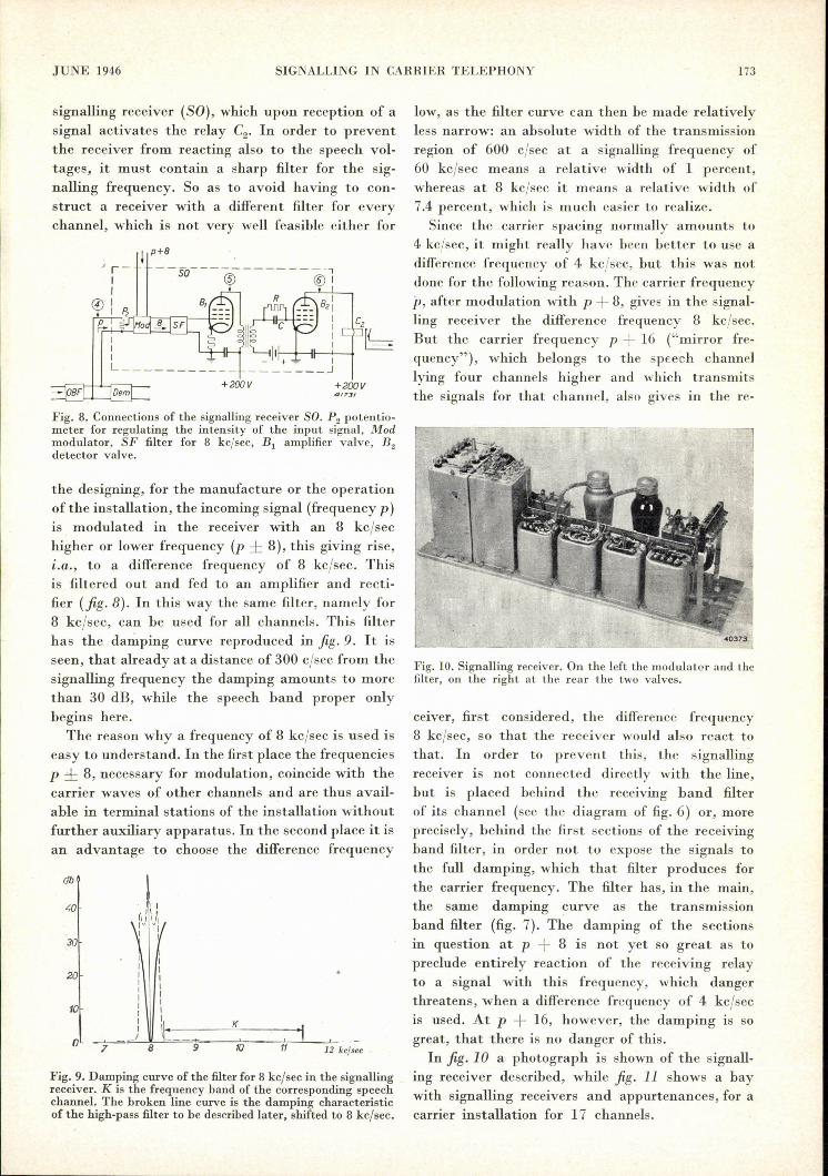
signalling receiver (SO), which upon reception of asignal activates the relay C2• In order to preventthe receiver from reacting also to the speech vol-tages, it must contain a sharp filter for the sig-nalling frequency. So as to avoid having to con-struct a receiver with a different filter for everychannel, which is not very well feasible either for
I p+8
--SO------------
+200V +200V417::11
Fig. 8. Connections of the signallingreceiver SO. P2 potentio-meter for regulating the intensity of the input signal, Modmodulator, SF filter for 8 kc/sec, Bi amplifier valve, Bzdetector valve.
the designing, for the manufacture or the operationof the installation, the incoming signal (frequency p)is modulated in the receiver with an 8 kc/sechigher or lower frequency (p ± 8), this giving rise,i.a., to a difference frequency of 8 kc/sec. Thisis filtered out and fed to an amplifier and recti-fier (fig. 8). In this way the same filter, namely for8 kc/sec, can be used for all channels. This filterhas the damping curve reproduced in fig. 9. It isseen, that already at a distance of 300 c/sec from thesignalling frequency the damping amounts to morethan 30 dB, while the speech band proper onlybegins here.
The reason why a frequency of 8 kc/sec is used iseasy to understand. In the first place the frequenciesp ± 8, necessary for modulation, coincide with thecarrier waves of other channels and are thus avail-able in terminal stations of the installation withoutfurther auxiliary apparatus. In the second place it isan advantage to choose the difference frequency
db
,.0
30
II
20 IIII
10 III KI
0I=r=: 9 10 11 12 kc/sec
Fig. 9. Damping curve of the filter for 8 kc/sec in the signallingreceiver. K is the frequency band of the corresponding speechchannel. The broken line curve is the damping characteristicof the high-pass filter to be describedlater, shifted to 8 kc/sec.
low, as the filter curve can then be made relativelyless narrow: an absolute width of the transmissionregion of 600 cleec at a signalling frequency of60 kc/sec means a relative width of 1 percent,whereas at 8 kc/sec it means a relative width of7.4 percent, which is much easier to realize.Since the carrier spacing normally amounts to
4 kc/sec, it might really have been better to use adifference frequency of 4 kc/sec, but this was notdone for the following reason. The carrier frequency'p, after modulation with p + 8, giveE in the signal-ling receiver the difference frequency 8 kc/sec.But the carrier frequency p + 16 ("mirror fre-quency"), which belongs to the speech channellying four channels higher and which transmitsthe signals for that channel, also gives in the re-
Fig. 10. Signalling receiver. On the left the modulator and thefilter, on the right at the rear the two valves.
ceiver, first considered, the difference frequency8 kc/sec, so that the receiver would also react tothat. In order to prevent this, the signallingreceiver is not connected directly with the line,but is placed behind the receiving band filterof its channel (see the diagram of fig. 6) or, moreprecisely, behind the first sections of the receivingband filter, in order not to expose the signals tothe full damping, which that filter produces forthe carrier frequency. The filter has, in the main,the same damping curve as the transmissionband filter (fig. 7). The damping of the sectionsin question at p + 8 is not yet so great as topreclude entirely reaction of the receiving relayto a signal with this frequency, which dangerthreatens, when a difference frequency of 4 kc/secis used. At p + 16, however, the damping is sogreat, that there is no danger of this.In fig. 10 a photograph is shown of the signall-
ing receiver described, while fig. 11 shows a baywith signalling receivers and appurtenances, for acarrier installation for 17 channels.
174 PHILIPS TECHNICAL REVIEW
Distortion of the signals
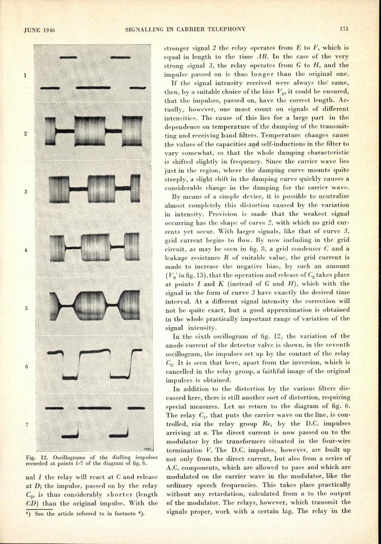
We have seen that the earner signals must pass through thetransmission band filter and the receiving band filter,_among others.These filters suppress the side-band frequencies, which fall in theirdamping region, and also cause a relative attenuation of thosefrequencies, which fall in the transition region between damping andtransmission, namely the carrier wave itself and the 30 lowest har-monics of the dialling impulses. This results in a certain (slight)distortion of the dialling impulses, as may be seen in the oscillo-grams of fig. 12. The first oscillogram shows the dialling impulses, asgiven with direct current (point 1 in fig. 6). The second oscillogramgives the voltage in front of the transmission band filter; during thetime that the incoming line is not carrying current the carrier waveis transmitted (transition from the continuous to impulse signalling).These carrier impulses are practically rectangular. The third pictureshows the impulses behind the transmission band filter, amplifiedin the transmission amplifier. Some rounding off has taken place.In the case of the input signalof the signalling receiver, oscillogramno. 4, the rounding off has become somewhat greater, owing to theinfluenee of the receiving band filter.
The most important distortion, howéver, occurs in the followingstep: the filtering out of the 8 kc/sec frequency by the sharp filter inthe signalling receiver. Here, since it is a question of eliminating thespeech frequencies, the higher harmonics of the dialling impulsesare attenuated. At 300 ejeee, i.e. the 30th harmonic, the dampingof this filter, as already mentioned, is 30 dB; but also the 5thharmonic, for instance, is already attenuated by 6 dB. The resultantconsiderable rounding off of the impulse may be seen in the fifthoscillogram of fig. 12.
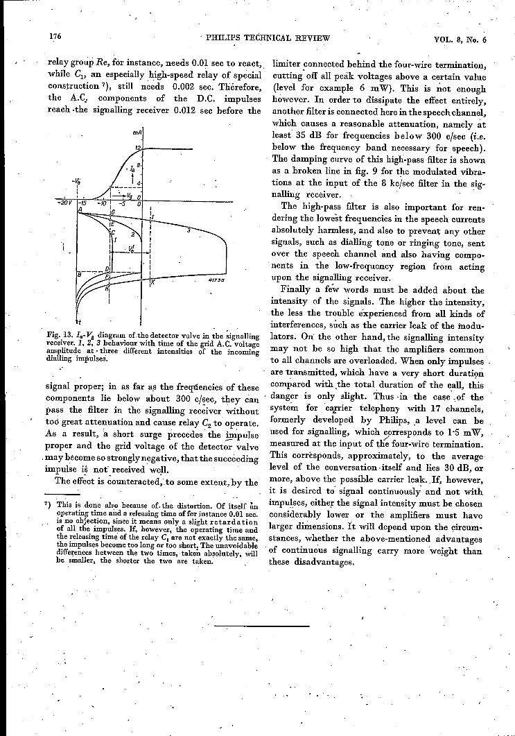
What is in fact of importance with dialling impulses is the need tokeep to their correct length. A closer examination of the func-tioning of the signalling receiver (fig. 8) shows, to what extent errorsmay occur in this length, as a result of the rounding off of the impulses.After passing the filter the signals are amplified and fed to a valve(B2) acting as anode detector. The la- Vg characteristic of the valve(anode direct current as a function of the grid A.C. voltage amplitude)is drawn infig. 13. The fixed negative bias - Vo of the grid is chosenso large, that plate current only begins to flow at several volts signalvoltage. (This threshold voltage, below which the receiver does notwork at all, gives an extra security against slight interferences, suchas the carrier leak of the modulator at the transmitting end.)
With a sufficiently intense signal, plate current begins to flow;the relay C2 will react as soon as the plate direct current hasreached a value of 3 mA. The impulse transmitted thus becomesrectangular again in any case, but what about its length? Infig. 13 the variation of the grid A.C. voltage amplitude is -drawnfor the case, where the rounded off dialling impulses, reaching thegrid, have the form of oscillogram no. 5, dialling impulses of threedifferent intensities being assumed. The length of the originalimpulse is A B in all three cases. In the case of the weak sig-
Fig. 11. Bay with signalling receivers and relays of a carrier installation for 17channels (11 of the 18 receivers are mounted on the back of the bay; one receiverserves as reserve).
VOL. 8, No. 6
JUNE 1946 SIGNALLING IN CARRIER TELEPHONY 175
- -1 - -2
3
4
5
6
-7
Fig. 12. Oscillograms of the dialling impulsesrecorded at points 1-7 of the diagram of fig. 6.
naIl the relay will react at C and releaseat D; the impulse, passed on by the relayC2, is thus considerably shorter (lengthCD) than the original impulse. With the6) See the article referred to in footnote 4).
stronger signal 2 the relay operates from E to F, which isequal in length to the time AB. In the case of the verystrong signal 3, the relay operates from G to H, and theimpulse passed on is thus longer than the original one.
H the signal intensity received were always the' same,then, by a suitable choice of the bias Vo' it could be ensured,that the impulses, passed on, have the correct length. Ac-tually, however, one must count on signals of differentirrtensit.ies. The cause of this lies for a large part in thedependence on temperature of the damping of the transmit-ting and receiving band filters. Temperature changes causethe values of the capacities a!!cl.self-inductions in the filter tovary somewhat, so that the whole damping characteristicis shifted slightly in frequency. Since the carrier wave liesjust in the region, where the damping curve mounts quitesteeply, a slight shift in the damping curve quickly causes aconsiderable change in the damping for the carrier wave.By means of a simple device, it is possible to neutralize
almost completely this distortion caused by the variationin intensity. Provision is made that the weakest signaloccurring has the shape of curve 2, with which no grid cur-rents yet occur. With larger signals, like that of curve 3,grid current begins to flow. By now including in the gridcircuit, as may be secn in fig. 8, a grid condenser C and aleakage resistance R of suitable value, the grid current ismade to increase the negative bias, by such an amount(Vo' in fig. 13), that the operation and release of C2 takes placeat points I and J( (instead of G and H), which with thesignal in the form of curve 3 have exactly the desired timeinterval. At a different signal intensity the correction willnot be quite exact, but a good approximation is obtainedin the whole practically important range of variation of thesignal intensity.
In the sixth oscillogram of fig. 12, the variation of theanode current of the detector valve is shown, in the seventhoscillogram, the impulses set up by the contact of the relayC2• It is seen that here, apart from the inversion, which iscancelled in the relay group, a faithful image of the originalimpulses is obtained.
In addition to the distortion by the various filters dis-cussed here, there is still another sort of distortion, requiringspecial measures. Let us return to the diagram of fig. 6.The relay Cl' that puts the carrier wave on the line, is con-trolled, via the relay group Re, by the D.C. impulsesarriving at a. The direct current is now passed on to themodulator by the transformers situated in the four-wiretermination V. The D.e. impulses, however, are built upnot only from the direct current, but also from a series ofA.C. components, which are allowcd to pass and which aremodulated on the carrier wave in the modulator, like theordinary speech frequencies. This takes place practicallywithout any retardation, calculated from a to the outputof the modulator. The relays, however, which transmit thesignals proper, work with a certain lág. The relay in the
176 . PHILIPS TEèHNICAL REVIEW VOL. 8, No. 6
relay group Re, for instance, needs 0.01 sec to react"while Cl' an especially high-speed relay of specialconstruction 7), still needs 0.002 sec. Tliérefore,the A.C.. components of the D.C. impulsesreach -the signalling receiver 0.012 sec before the
mA
-2DV -15A
4173J
t
Fig. 13. Ia- ~ diagram of.the detector valve in the signallingreceiver. 1, 2, 3 behaviour with time of the grid A.C. voltageamplitude .at.- three different intensities of the incomingdialling impulses.
.:
signal proper; in as far as the frequencies of thesecomponents lie below about 300 c/~ec, they canpass the filter in the signalling receiver withoutt06 great attenuation and cause relay C2 to operate.As a result, a short surge precedes the i-m:pulseproper and the grid voltage of the detector valve.may become so stronglynegative, that thesucceedingimpulse is not' received' well. ', The eff~ct is ~ounteracted: to some extent, by the
7) This is done also because of. the distortion. Of itself ánoperating time and a releasing time offor instance 0.01 sec.is no objection, since it means only a slight retardationof all the impulses. If, however, the operating time andthe releasing time of the relay Cl are not exactly the same,the impulses become too long or too short: The unavoidabledifferences between the two times, -taken absolutely, willhe smaller, the shorter the two are taken. .
limiter connected behind the four-wire termination,cutting' off all peàk voltages above a certain value(level for example 6 mW). This is not enoughhowever. In order to dissipate the effect entirely,another filter is connected here in the speech channel,which causes a reasonable attenuation, namely atleast 3S dB for frequencies below 300 c/sec (i.e.below the frequency band necessary for speech).The damping curve of this high-pass filter is shownas a broken line in fig. 9 for the modulated vibra-tions at the input of the 8 kc/sec filter in the sig-nalling receiver.The high-pass filter is also important for ren-
dering the lowest frequencies in the speech currentsabsolutely harmless, and also to prevent any othersignals, such as dialling tone or ringing tone, sentover the speech channel and also having compo-nents in the low-frequency region from actingupon the signalling receiver.Finally a few words must be added about the
intensity of the signals. The higher the intensity,the less the trouble experienced from all kinds ofinterferences, such as the carrier leak of the modu-lators. On' the other hand, the signalling intensitymay not be so high that the amplifiers commonto all channels are overloaded. When only impulsesare transmitted, which have a very short durationcompared with ,the total, duration of the call, thisdanger is only slight. Thus vin the case .of thesystem for 'c~!rier telephony with 17 channels,formerly developed by Philips,.a level can beused for signalling, 'which cprresponds to l·S mW,measured at the input of t:lie four-wire termination.This corresponds, approximately, to the averagelevel of the conversation ,itself and lies 30 dB, ormore, above the possible carrier leak .. If, however,it is desired to' signal continuously and not withImpulses, either the signal intensity must be chosenconsiderably lower, or the amplifiers must havelarger dimensions. It will depend upon the circum-stances, whether the above-mentioned advantages.of continuous signalling carry more weight thanthese disadvantages.